JP2010028815A - Ultrasonic transducer - Google Patents
Ultrasonic transducer Download PDFInfo
- Publication number
- JP2010028815A JP2010028815A JP2009167031A JP2009167031A JP2010028815A JP 2010028815 A JP2010028815 A JP 2010028815A JP 2009167031 A JP2009167031 A JP 2009167031A JP 2009167031 A JP2009167031 A JP 2009167031A JP 2010028815 A JP2010028815 A JP 2010028815A
- Authority
- JP
- Japan
- Prior art keywords
- casing
- region
- ultrasonic transducer
- ultrasonic
- resonator
- Prior art date
- Legal status (The legal status is an assumption and is not a legal conclusion. Google has not performed a legal analysis and makes no representation as to the accuracy of the status listed.)
- Granted
Links
Images


Classifications
-
- G—PHYSICS
- G10—MUSICAL INSTRUMENTS; ACOUSTICS
- G10K—SOUND-PRODUCING DEVICES; METHODS OR DEVICES FOR PROTECTING AGAINST, OR FOR DAMPING, NOISE OR OTHER ACOUSTIC WAVES IN GENERAL; ACOUSTICS NOT OTHERWISE PROVIDED FOR
- G10K9/00—Devices in which sound is produced by vibrating a diaphragm or analogous element, e.g. fog horns, vehicle hooters or buzzers
- G10K9/18—Details, e.g. bulbs, pumps, pistons, switches or casings
- G10K9/22—Mountings; Casings
-
- G—PHYSICS
- G01—MEASURING; TESTING
- G01F—MEASURING VOLUME, VOLUME FLOW, MASS FLOW OR LIQUID LEVEL; METERING BY VOLUME
- G01F1/00—Measuring the volume flow or mass flow of fluid or fluent solid material wherein the fluid passes through a meter in a continuous flow
- G01F1/66—Measuring the volume flow or mass flow of fluid or fluent solid material wherein the fluid passes through a meter in a continuous flow by measuring frequency, phase shift or propagation time of electromagnetic or other waves, e.g. using ultrasonic flowmeters
- G01F1/662—Constructional details
-
- G—PHYSICS
- G10—MUSICAL INSTRUMENTS; ACOUSTICS
- G10K—SOUND-PRODUCING DEVICES; METHODS OR DEVICES FOR PROTECTING AGAINST, OR FOR DAMPING, NOISE OR OTHER ACOUSTIC WAVES IN GENERAL; ACOUSTICS NOT OTHERWISE PROVIDED FOR
- G10K11/00—Methods or devices for transmitting, conducting or directing sound in general; Methods or devices for protecting against, or for damping, noise or other acoustic waves in general
- G10K11/002—Devices for damping, suppressing, obstructing or conducting sound in acoustic devices
Abstract
Description
本発明は、超音波変換器であって、ケーシングを備え、ケーシングの第1の領域内に設けられている、前記超音波変換器の内室と前記超音波変換器の外室との間における超音波の伝播のための超音波窓を備え、ケーシング内で超音波窓に隣接して配置されている変換エレメントを備え、超音波はケーシング波として、ケーシングの第1の領域と、ケーシングの少なくとも1つの仲介する第2の領域を介して、ケーシングの第1の領域に相対する、ケーシングの第3の領域との間を伝播可能である、超音波変換器に関する。 The present invention is an ultrasonic transducer comprising a casing and provided in a first region of the casing, between the inner chamber of the ultrasonic transducer and the outer chamber of the ultrasonic transducer. An ultrasonic window for the propagation of ultrasonic waves, comprising a conversion element arranged in the casing adjacent to the ultrasonic window, the ultrasonic wave being a casing wave, the first region of the casing and at least the casing The present invention relates to an ultrasonic transducer capable of propagating between a third region of the casing, which is opposite to the first region of the casing, through one intermediate second region.
前記形式の超音波変換器は数年前から公知であり、例えば音響による流量測定機器においては大規模に使用されている。超音波変換器の変換エレメントは、適切な励振時に電気的なエネルギを機械的な変位に、つまり超音波領域の振動に変換する。この場合、超音波変換器は超音波発信器として働き、超音波は部分的に超音波窓を介して超音波変換器を取り囲む媒体に伝播される。 Ultrasonic transducers of this type have been known for several years, and are used on a large scale, for example, in acoustic flow measurement equipment. The transducer element of the ultrasonic transducer converts electrical energy into mechanical displacements, i.e. vibrations in the ultrasonic range, when appropriately excited. In this case, the ultrasonic transducer acts as an ultrasonic transmitter, and the ultrasonic waves are propagated partially through the ultrasonic window to the medium surrounding the ultrasonic transducer.
逆に、超音波窓は媒体内に発生する外部の圧力変動により変位され、この変位は変換エレメントにより適切な信号に変換される、ということも可能である。この場合、超音波変換器は超音波受信器としても働く。例えば充填状態測定といった多様な使用において、この種の超音波変換器は、超音波発信器及び超音波受信器としても使用され、流量測定の領域では、超音波変換器は頻繁に超音波発信器又は超音波受信器として使用される。 Conversely, it is also possible that the ultrasonic window is displaced by external pressure fluctuations occurring in the medium, and this displacement is converted into an appropriate signal by the conversion element. In this case, the ultrasonic transducer also functions as an ultrasonic receiver. In various uses, for example filling state measurement, this type of ultrasonic transducer is also used as an ultrasonic transmitter and an ultrasonic receiver, and in the area of flow measurement, an ultrasonic transducer is frequently used as an ultrasonic transmitter. Or it is used as an ultrasonic receiver.
両事例、つまり超音波変換器が発信器として働く事例においても、超音波変換器が受信器として働く事例においても、変換エレメントに到達するか、もしくは変換エレメントから発生する、超音波窓を介して伝播される超音波は、実際には重要な有効信号である。ケーシングを介して更に伝播されるか、もしくは導き出される冒頭で述べた超音波は、寄生のケーシング波である。この波と共に伝播されるエネルギは有効信号を提供しない。従ってケーシング波は一般的には不都合なものである。 In both cases, the case in which the ultrasonic transducer acts as a transmitter, and the case in which the ultrasonic transducer acts as a receiver, either through the ultrasonic window that reaches or originates from the conversion element. The propagated ultrasound is actually an important useful signal. The ultrasound mentioned at the beginning which is further propagated or derived through the casing is a parasitic casing wave. The energy propagated with this wave does not provide a useful signal. The casing wave is therefore generally inconvenient.
ケーシング波を減じるために種々異なる手段がある。幾つかの手段は、この種のケーシング波を発生時に既に回避するという役割を有している。更に、伝達されるエネルギ部分の最大化のために特に良好なインピーダンス適合に対する、又は反響を減じるためのλ/4層としての超音波窓の設計に対する超音波窓の、例えば規定された構成が重要である。他の手段は、既に発生したケーシング波の更なる伝播を、例えば不整合の音響的なインピーダンス移行により防ぐことに関する。しかしケーシング波は有効信号にとって失われた損失出力であるだけでなく、更に別の不都合な作用を有していることがある。 There are different ways to reduce the casing wave. Some means have the role of avoiding this type of casing wave already when it occurs. Furthermore, the defined configuration of the ultrasonic window, for example, for a particularly good impedance fit for maximizing the transmitted energy part or for the design of an ultrasonic window as a λ / 4 layer to reduce reverberation is important It is. Other measures relate to preventing further propagation of the already generated casing waves, for example by mismatched acoustic impedance transitions. However, the casing wave is not only a lost output for the useful signal, but may also have other adverse effects.
音響による流量測定の場合には、例えば測定管内を搬送される媒体において、媒体の搬送速度は、音響信号の拡散速度に重畳されているという効果が大抵利用される。測定管に対する音響信号の測定された拡散速度は、音響信号の方向に媒体が搬送される場合には、媒体が止まっている場合よりも大きく、測定管に対する音響信号の速度は、媒体が音響信号の放射方向とは反対に搬送される場合には、媒体が止まっている場合よりも僅かである。音響発信器と音響受信器との間の音響信号(両者とも超音波変換器)の所要時間は、連行効果に基づいて、測定管、ひいては音響発信器及び音響受信器に対する媒体の搬送速度に基づいている。 In the case of acoustic flow measurement, for example, in a medium transported in a measuring tube, the effect that the transport speed of the medium is superimposed on the diffusion speed of the acoustic signal is often used. The measured diffusion rate of the acoustic signal to the measuring tube is greater when the medium is transported in the direction of the acoustic signal than when the medium is stationary, and the velocity of the acoustic signal to the measuring tube is When transported in the direction opposite to the radial direction, the amount is slightly smaller than when the medium is stopped. The time required for the acoustic signal between the acoustic transmitter and the acoustic receiver (both ultrasonic transducers) is based on the entrainment effect and based on the transport speed of the medium with respect to the measuring tube and hence the acoustic transmitter and acoustic receiver. ing.
放出された音響信号又は超音波信号に基づく測定時には、流量測定の領域において、変換エレメントによって形成された超音波速度が変換器ケーシングの超音波窓を介してのみ超音波変換器の周辺の媒体に伝播されるだけでなく、形成された超音波振動が部分的にもケーシングを介してケーシング波として全測定装置に伝播されるということが問題である。このことは損失出力とは別に、いわゆるクロストークにより測定機器ケーシングに伝播された超音波が、受信側での著しい障害に繋がることもあるので問題である。このことは、受信された超音波信号が、媒体及び超音波窓を介して直接受信されたか(有効信号)、又はケーシング波として測定装置及び超音波変換器の全ケーシングを間接的に介して、特につまりケーシングの第3の領域と、ケーシングの仲介する第2の領域とを介して変換エレメントに到達したかどうかを受信側で簡単に認識できないことに基づく。 During the measurement based on the emitted acoustic or ultrasonic signal, in the flow measurement area, the ultrasonic velocity formed by the conversion element is applied to the medium surrounding the ultrasonic transducer only through the ultrasonic window of the transducer casing. In addition to being propagated, the problem is that the ultrasonic vibrations formed are also partially propagated through the casing as a casing wave to all measuring devices. This is a problem because, apart from the loss output, the ultrasonic waves propagated to the measuring device casing by so-called crosstalk may lead to a significant failure on the receiving side. This means that the received ultrasonic signal was received directly via the medium and the ultrasonic window (valid signal) or indirectly through the entire casing of the measuring device and the ultrasonic transducer as a casing wave, In particular, this is based on the fact that the receiving side cannot easily recognize whether the conversion element has been reached via the third region of the casing and the second region mediated by the casing.
従って、本発明の課題は、超音波変換器のケーシングを介するケーシング波の伝播を回避するための更なる手段を形成し、先行技術から公知の欠点を少なくとも部分的に回避する超音波変換器を提供することである。 The object of the present invention is therefore to provide an ultrasonic transducer which forms a further means for avoiding the propagation of casing waves through the casing of the ultrasonic transducer and which at least partially avoids the disadvantages known from the prior art. Is to provide.
上記課題を解決するために本発明に係る超音波変換器は、ケーシングの第2の領域において、弱く連結されている少なくとも2つの機械的な共振器が形成されており、該共振器はケーシング波の拡散方向でほぼ直列に配置されているようになっている。 In order to solve the above-described problem, an ultrasonic transducer according to the present invention includes at least two mechanical resonators that are weakly connected in the second region of the casing, and the resonator is a casing wave. Are arranged in series in the diffusion direction.
好ましくは、共振器の固有周波数は、ケーシング波の周波数範囲内にある。 Preferably, the natural frequency of the resonator is within the frequency range of the casing wave.
好ましくは、ケーシングの第2の領域は軸線方向の経過方向でスリーブ状に形成されており、少なくとも1つの共振器は、上側の平坦壁と、下側の平坦壁と、上側の平坦壁及び下側の平坦壁を結合する端壁とを備えた、中空リング又は段部として形成されている。 Preferably, the second region of the casing is formed in a sleeve shape in the axial direction and the at least one resonator comprises an upper flat wall, a lower flat wall, an upper flat wall and a lower flat wall. It is formed as a hollow ring or step with an end wall joining the side flat walls.
好ましくは、前記中空リングは、ケーシングの第2の領域のほぼ軸線方向の経過方向に方向付けられており、特にケーシングの第2の領域は前記中空リングの領域において、経過方向でメアンダ形状に延在している壁横断面を有している。 Preferably, the hollow ring is oriented in a substantially axial direction of the second region of the casing, in particular the second region of the casing extends in a meander shape in the direction of passage in the region of the hollow ring. It has an existing wall cross section.
好ましくは、軸線方向の経過方向で端壁の剛性は、上側の平坦壁の剛性及び/又は下側の平坦壁の剛性よりも大きく、特に少なくとも1つのサイズオーダだけ大きく、有利には少なくとも2つのサイズオーダだけ大きく設定されている。 Preferably, the stiffness of the end wall in the axial direction is greater than the stiffness of the upper flat wall and / or the stiffness of the lower flat wall, in particular greater by at least one size order, advantageously at least two Only the size order is set larger.
少なくとも1つの共振器は、特に1つの共振器内に配置されている且つ/又は2つの共振器の間に配置されている、又は1つの共振器に隣接して配置されている少なくとも1つの減衰エレメントにより減衰されている。 The at least one resonator is arranged in particular in one resonator and / or between two resonators or at least one attenuation arranged adjacent to one resonator It is attenuated by the element.
好ましくは、減衰エレメントは少なくとも1つのOリング又は注型材料であり、特に弾性的又は粘弾性的な材料から成っている。 Preferably, the damping element is at least one O-ring or casting material, in particular made of an elastic or viscoelastic material.
また、上記課題を解決するために本発明に係る超音波変換器は、ケーシングの第2の領域は軸線方向の経過方向においてスリーブ状に形成されており、ケーシングの第2の領域に少なくとも1つの機械的な共振器が形成されており、共振器は、上側の平坦壁と、下側の平坦壁と、上側の平坦壁及び下側の平坦壁を結合する端壁とを備えた、中空リング又は段部として形成されていることを特徴とする。 In order to solve the above-mentioned problem, in the ultrasonic transducer according to the present invention, the second region of the casing is formed in a sleeve shape in the axial direction, and at least one of the second regions of the casing is provided in the second region. A mechanical resonator is formed, the resonator comprising a hollow ring having an upper flat wall, a lower flat wall, and an end wall connecting the upper flat wall and the lower flat wall. Or it is formed as a step part.
好ましくは、共振器は、請求項2又は3から6までのいずれか一項記載の特徴部に基づいて形成されている。
Preferably, the resonator is formed on the basis of the characteristic part according to any one of
超音波変換器もしくは超音波変換器のケーシングの第2の領域の本発明に係る構成は、種々異なる利点を必然的に有している。機械的な共振器により、まず、超音波によって伝播されたエネルギを局地的に「捕らえる」、つまり機械的な共振器の励振により振動することが可能である。機械的な共振器は、一般的にはばね質量系(Feder−Masse−System)として記載可能である。実際のばね質量系ではばねの特性、すなわち変位に関係する力作用は、ちょうどまさに質量体が共振器への構造的な貢献に基づきばね質量系のばね特性に常に影響を与えてもいるように、共振器の質量へ僅かであっても必ず作用するように実現可能である。ばね及び質量は構造的には実際には完全に分離することはできない。少なくとも2つの機械的な共振器をケーシング波の拡散方向で直列に配置することにより、ケーシングの第1の領域からケーシングの第3の領域、及びケーシングの第3の領域からケーシングの第1の領域に達するために、ケーシング波は全共振器を横断しなければならない、ということになる。両共振器の弱い連結により、共振器はケーシング波に対して全体として、共振器自体が同じ振動特性を有していたとしても強く連結された共振器の場合よりも大きな妨害となる。強い機械的な連結時には、1つの共振器の振動は間接的に隣接する共振器に有利に伝播される。このことは、隣接する共振器の間に機械的な交番作用が当然に与えられてはいるものの、弱い機械的な連結時には当てはまらない。 The configuration according to the invention in the second region of the ultrasonic transducer or the casing of the ultrasonic transducer necessarily has different advantages. With a mechanical resonator, it is possible to first “capture” the energy propagated by the ultrasound, ie vibrate by excitation of the mechanical resonator. Mechanical resonators can generally be described as a spring-mass system. In the actual spring mass system, the spring characteristics, ie the force action related to the displacement, just as the mass body always influences the spring characteristics of the spring mass system based on the structural contribution to the resonator. It is feasible to always work even a small amount on the mass of the resonator. In practice, the spring and mass cannot be completely separated in practice. By arranging at least two mechanical resonators in series in the diffusion direction of the casing wave, from the first region of the casing to the third region of the casing and from the third region of the casing to the first region of the casing This means that the casing wave must traverse all the resonators in order to reach Due to the weak coupling of the two resonators, the resonator as a whole becomes a greater disturbance to the casing wave than in the case of a strongly coupled resonator, even if the resonator itself has the same vibration characteristics. During strong mechanical coupling, the vibration of one resonator is propagated advantageously to the adjacent resonator indirectly. This is not the case with weak mechanical connections, although a mechanical alternating action is naturally given between adjacent resonators.
本発明の有利な構成において、共振器の固有周波数はケーシング波の周波数範囲内にある。これにより振動可能なシステムの共振効果に基づき、ケーシング波の可能限り多くのエネルギが共振器の振動において結合することが保証されている。種々異なる固有周波数を形成する共振器では、広幅な周波数範囲のケーシング波を抑えることができる。このことは特に、広帯域の超音波信号の放射又は放出時には重要である。従ってケーシングの第2の領域に設けられている弱く連結された機械的な共振器は、有利には、1つの帯域消去フィルタ(又は複数の帯域消去フィルタ)として、超音波変換器の第1の領域から超音波変換器の第3の領域への伝播経路において働く。 In an advantageous configuration of the invention, the natural frequency of the resonator is in the frequency range of the casing wave. This ensures that as much energy as possible of the casing wave is coupled in the vibration of the resonator, based on the resonance effect of the oscillatable system. In a resonator that forms different natural frequencies, casing waves in a wide frequency range can be suppressed. This is particularly important when emitting or emitting broadband ultrasonic signals. Accordingly, the weakly coupled mechanical resonator provided in the second region of the casing is advantageously used as one band-eliminating filter (or a plurality of band-eliminating filters) as the first of the ultrasonic transducer. Works in the propagation path from the region to the third region of the ultrasonic transducer.
本発明の別の有利な構成において、ケーシングの第1の領域及び/又はケーシングの第3の領域は、ケーシングの第1の領域及び/又はケーシングの第3の領域の共振周波数が、設計上是認しうる範囲において、ケーシングの第2の領域の弱く連結された共振器の固有周波数から可能な限り十分に離れている、ひいては超音波変換器の作業周波数から可能な限り十分に離間されているように設計されている。 In another advantageous configuration of the present invention, the first region of the casing and / or the third region of the casing is designed to allow the resonant frequency of the first region of the casing and / or the third region of the casing to be design approved. To the extent possible, it is as far as possible from the natural frequency of the weakly coupled resonator in the second region of the casing and thus as far as possible from the working frequency of the ultrasonic transducer. Designed to.
超音波変換器は、ケーシングの第2の領域において軸線方向の延在方向でよくスリーブ状に構成されている。ケーシングの第1の領域における超音波窓は、スリーブを端面として媒体に対して閉鎖する。ケーシングのスリーブ状に形成された第2の領域は、大抵円筒状である。ケーシングの第1の領域に相対している、ケーシングの第3の領域は、例えばフランジ状の接続部材であってよいか、又はスリーブの単に開放した端部領域であってもよい。上述のように構成された超音波変換器の場合、ケーシング波は既にケーシングを介して全体として軸線方向の経過方向でも伝播する。本発明の更に別の有利な構成によれば、上述のように構成された超音波変換器では、少なくとも1つの共振器は、上側の平坦壁と、下側の平坦壁と、上側の平坦壁及び下側の平坦壁を結合する端壁とを備えた、中空リング又は段部として形成されているようになっている。中空リング又は段部である1つの共振器の構成は、両構造が製造技術的に極めて簡単で、高い精度をもって、例えば切削加工による回転により固形物からワンピースで製造可能であるので有利である。上側の平坦壁と、下側の平坦壁と、上側の平坦壁及び下側の平坦壁を結合する端壁とにより制限された極めて低く、平坦壁の延在方向に十分に拡張している中空室を有する比較的大きな中空リングは、複数の部材からの構成により、場合によっては比較的簡単に製造することができる。 The ultrasonic transducer is often configured in a sleeve shape in the axial direction in the second region of the casing. The ultrasonic window in the first region of the casing closes against the medium with the sleeve as the end face. The second region formed in the casing sleeve shape is generally cylindrical. The third region of the casing, which is opposite to the first region of the casing, may be for example a flange-like connecting member or may be simply the open end region of the sleeve. In the case of the ultrasonic transducer configured as described above, the casing wave already propagates through the casing as a whole even in the axial direction. According to yet another advantageous configuration of the invention, in the ultrasonic transducer configured as described above, at least one resonator comprises an upper flat wall, a lower flat wall, and an upper flat wall. And an end wall that joins the lower flat wall and is formed as a hollow ring or step. The configuration of one resonator, which is a hollow ring or step, is advantageous because both structures are very simple in terms of manufacturing technology and can be manufactured in one piece from solids with high accuracy, for example by rotation by cutting. A hollow that is sufficiently low in the extending direction of the flat wall, limited by the upper flat wall, the lower flat wall, and the end wall joining the upper flat wall and the lower flat wall. A relatively large hollow ring with chambers can be produced relatively easily in some cases by virtue of the construction of a plurality of members.
本発明の更に別の有利な構成では、中空リングは、ケーシングの第2の領域の軸線方向のほぼ経過方向に方向付けられている。ケーシングの第2の領域は、中空リングの領域では軸線方向の経過方向で、特にメアンダ形状に延在する壁横断面を有している。この記載は、ケーシングの第1の領域からケーシングの第3の領域に達するためにケーシング波は、直列された共振器を必然的に通過しなければならず、つまり共振器は強制的に連続して励振し、いずれにしても超音波変換器のケーシングに当てはまる場合には、共振器を避けて通ることはできない、ということを明らかにしている。 In a further advantageous configuration of the invention, the hollow ring is oriented approximately in the axial direction of the second region of the casing. The second region of the casing has a wall cross section extending in the axial direction in the region of the hollow ring, in particular in a meander shape. This description states that in order to reach the third region of the casing from the first region of the casing, the casing wave must inevitably pass through the series of resonators, i.e. the resonator is forced to continue. It is clarified that if it is applied to the casing of the ultrasonic transducer in any case, the resonator cannot be avoided.
上記超音波変換器において、第1の平坦壁の剛性及び/又は第2の平坦壁の剛性よりも、中空リング又は段部の端壁の剛性が軸線方向の経過方向において大きい場合には、特に有利である。この手段により、共振器の振動は軸線方向の経過方向において極めて簡単に可能であり、簡単に励振できる。既述したように共振器がばね質量系と見なされる場合、端壁は、質量の実質的な部分に寄与する共振器の構成要素であり、第1の平坦壁及び/又は第2の平坦壁は、実質的にばね質量系のばね弾性的な特性を変換する。隣り合う共振器の間の弱い連結を達成するために、端壁の剛性が、軸線方向の延在方向で見て、少なくとも1つのサイズオーダだけ、それどころか又は2以上のサイズオーダだけ、第1の平坦壁の剛性及び/又は第2の平坦壁の剛性よりも大きいと有利である。 In the ultrasonic transducer, particularly when the rigidity of the end wall of the hollow ring or the step portion is larger in the axial direction than the rigidity of the first flat wall and / or the second flat wall, It is advantageous. By this means, the vibration of the resonator can be very easily performed in the axial direction, and can be easily excited. If the resonator is considered to be a spring mass system as already mentioned, the end wall is a component of the resonator that contributes to a substantial part of the mass and is the first flat wall and / or the second flat wall. Substantially converts the spring elastic properties of the spring mass system. In order to achieve a weak connection between adjacent resonators, the stiffness of the end wall can be as high as at least one size order, or even two or more size orders, as viewed in the axial direction of extension. It is advantageous if it is greater than the rigidity of the flat wall and / or the rigidity of the second flat wall.
本発明の別の、とりわけ独立した構成によれば、冒頭で述べた超音波変換器における上記課題は、ケーシングの第2の領域が軸線方向の経過方向でスリーブ状に形成されていて、ケーシングの第2の領域に少なくとも1つの機械的な共振器が形成されていることにより解決されている。共振器は、上側の平坦壁と、下側の平坦壁と、上側の平坦壁及び下側の平坦壁を結合する端壁とを備えた、中空リング又は段部として構成されている。確かに実務上、ケーシングの仲介する第2の領域に1つの機械的な共振器を有している超音波変換器は出願人には公知であるが、超音波変換器は更に複雑に構成されていて、それに応じて簡単には製造することはできない。これに対して中空リング又は段部としての共振器の構成は、製造技術的に極めて簡単で、ひいては廉価に実現することができる。振動可能なシステムのばね質量パラメータ−共振周波数、減衰量ひいては等級−は、極めて簡単に調節可能である。パラメータの調節は、有利には、平坦壁の肉厚−ばね定数−及び端壁の肉厚−質量−の適切な選択により行われる。弱く連結された共振器の有利な全構成は、伝播可能である限りは、唯一の共振器の有利な構成でもある。 According to another, in particular independent configuration of the present invention, the above-mentioned problem in the ultrasonic transducer mentioned at the outset is that the second region of the casing is formed in a sleeve shape in the direction of the axial direction. This is solved by forming at least one mechanical resonator in the second region. The resonator is configured as a hollow ring or step with an upper flat wall, a lower flat wall, and an end wall connecting the upper flat wall and the lower flat wall. Certainly, in practice, an ultrasonic transducer having one mechanical resonator in the second region mediated by the casing is known to the applicant, but the ultrasonic transducer has a more complicated construction. Therefore, it cannot be easily manufactured accordingly. On the other hand, the configuration of the resonator as a hollow ring or stepped portion is extremely simple in terms of manufacturing technology and can be realized at low cost. The spring mass parameters of the oscillatable system—resonance frequency, attenuation and thus the grade—can be adjusted very easily. The adjustment of the parameters is advantageously made by an appropriate selection of the flat wall thickness—spring constant—and the end wall thickness—mass. The advantageous overall configuration of weakly coupled resonators is also the only advantageous configuration of the resonator as long as it can propagate.
詳しくは、本発明による超音波変換器を構成し且つ改良する種々異なる手段がある。このために請求項1及び請求項8に従属している請求項、及び図面に関連した本発明の有利な実施の形態の記載が参照される。
In particular, there are different means for constructing and improving the ultrasonic transducer according to the present invention. For this purpose, reference is made to the claims dependent on
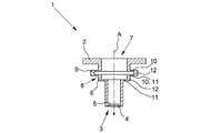
図1〜7にはそれぞれ超音波変換器1が記載されている。超音波変換器1は、ケーシング2と、ケーシング2の第1の領域3内に設けられている、超音波変換器1の内室と超音波変換器1の外室との間の超音波の伝播のための超音波窓4とを備えている。超音波自体は記載されていない。
1 to 7 each show an
更に記載された全超音波変換器1は、ケーシング2内において超音波窓4に隣接して配置されている変換エレメント5を有している。変換エレメント5は図示の実施の形態ではそれぞれ圧電結晶である。図面は、本発明を理解するために必要なエレメントだけを示す限りは、概略的に記載できる。従って、例えば変換エレメント5の励振に、及び変換エレメント5からの電気的な信号の選別に必要な電気的な配線は完全に省かれている。ケーシング2の第1の領域3の詳細な構造及び超音波窓4の構成については詳しく記載しない。第1の領域3及び超音波窓4は、極めて複雑に構成されていることがある。しかし本発明においては根本的に重要でない。本発明では、超音波変換器1のケーシング2が第1の領域3において1つの部材から形成されているか、又は複数の部材から形成されているかも重要ではない。種々異なる実施の形態が考慮可能であり、先行技術から種々異なる構成が公知である。
The further described
超音波変換器1が送信器として働く事例では、変換エレメント5により形成された超音波をケーシング2の内室から超音波窓4を介して超音波変換器1の外室に伝播することは、記載の超音波変換器1の優先的な目標である。変換エレメント5の励振に使う超音波の形式のエネルギの可能な限り大部分をケーシング2の外室に伝播することは極めて重要である。なぜならばこれによって実際の有効信号は最大であり、良好な信号対雑音比が達成される。
In the case where the
しかしながら超音波の一部分はケーシング波Gとして、ケーシング2の第1の領域3と、ケーシング2の仲介する第2の領域6を介して、ケーシング2の第1の領域3に相対している、ケーシング2の第3の領域7との間を伝播される、且つ伝播可能であることは回避できない。ケーシング波Gは実際に重要となる有効信号を提供する出力を減じるだけでなく、測定構造(図示せず)の別の構成要素にクロストークし、更に伝播されることがあり、直接伝播された有効超音波に別の場所で重畳することがある。このことは有効超音波の評価を困難にする。
However, a part of the ultrasonic wave is a casing wave G, which is opposed to the
ケーシング2の第3の領域は、記載された全実施の形態においてはフランジとして構成されている。図1ではケーシング波Gの可能な伝播方向が示されている。双方向矢印は、ケーシング波Gがケーシング2の第1の領域3からのみ出発して放射しているだけではなく、ケーシング2の第3の領域7内にも入力でき、ケーシング2の仲介する第2の領域6を介してケーシング2の第1の領域3に伝播することもできることを示している。
The third region of the casing 2 is configured as a flange in all described embodiments. In FIG. 1, possible propagation directions of the casing wave G are shown. The double-headed arrow not only radiates the casing wave G starting only from the
記載の超音波変換器は、ケーシング2の第2の領域6に、弱く連結された2つの機械的な共振器8,9が形成されていることを特徴とする。共振器8,9はケーシング波Gの拡散方向に直列に配置されている。記載の実施の形態では、ケーシング2の第1の領域3からケーシング2の第3の領域7、及びケーシング2の第3の領域7からケーシング2の第1の領域3に到達するために、ケーシング波Gは共振器8,9を介して及び通じて経過しなければならない、ということが強要されるので、機械的な共振器8,9はケーシング2内に形成されている。ケーシング波Gが機械的な共振器8,9に到達するやいなや、ケーシング波Gのエネルギは、少なくとも部分的に共振器8,9に蓄積される。なぜならば機械的な共振器8,9は励振されて振動するからである。従ってケーシング波Gと共に伝播されるエネルギを、少なくとも部分的に差し当たり局地的に限定することができる。従って、ケーシング波Gは妨害されずに、超音波変換器1のケーシング2の一方の端部からケーシング2の他方の端部に達することができるという目標が達成されている。まずエネルギは共振器8,9において「緩衝」され、次いで遅滞して比較的長い期間を介して再び放出される。これにより信号対雑音比は著しく改善される。実際の各共振器も減衰されているので、ケーシング波Gのエネルギの一部分は共振器8,9において熱に変換される。いずれにしても超音波の形式のエネルギとしてはもはや放出されない。
The described ultrasonic transducer is characterized in that two
共振器8,9の挙動は、特に、超音波変換器1もしくは変換エレメント5が、特に共振器振動が再び次第に消滅する間隔を置いて、周期的にインパルスにより励振される使用事例においては有利である。
The behavior of the
図1〜7に記載の超音波変換器1は、機械的な共振器8,9を有している。共振器8,9の固有周波数はケーシング波Gの周波数範囲内にある。これにより、ケーシング波Gの選択的な周波数部分を吸収することができるか、もしくはケーシング波Gの、ケーシング2の第1の領域3からケーシング2の第3の領域7への伝播、及びケーシング2の第3の領域7からケーシング2の第1の領域3への伝播を和らげることができる。
The
図1〜7において判るように、ケーシング2の仲介している第2の領域6は、軸線方向の経過方向Aにおいてスリーブ状に形成されている。経過方向Aにおいて、ケーシング波Gも超音波変換器1のケーシング2内で実質的に拡散する。図1〜4及び図6,7において、それぞれ記載されている両共振器8,9は、中空リングとして形成されている。各共振器8,9は上側の平坦壁10と、下側の平坦壁11と、上側の平坦壁10及び下側の平坦壁11を結合する端壁12とを有している。端壁12は、上側の平坦壁10と下側の平坦壁11とをそれぞれ環状に結合する。その結果、ケーシング2はケーシング2の第3の領域7において適切な接続部(図示せず)によって閉鎖される場合、記載の超音波変換器1のケーシング2は全体として密である。
As can be seen in FIGS. 1 to 7, the second region 6 mediated by the casing 2 is formed in a sleeve shape in the elapsed direction A in the axial direction. In the traveling direction A, the casing wave G is also substantially diffused in the casing 2 of the
図5には、段部として形成された共振器8と、中空リングとして形成された共振器9とを有する超音波変換器1が記載されている。段部として形成された共振器8では、上側の平坦壁10と下側の平坦壁11とは、軸線方向の経過方向Aで見て、スリーブ状に形成されたケーシングの直径拡幅部もしくは直径縮小部をもたらす。これに対して中空リングとして形成された共振器9においては、軸線方向の経過方向Aで、上側の平坦壁10と下側の平坦壁11とが相対している。
FIG. 5 shows an
図1〜7において、中空リングとして形成された共振器8,9は、中空リングの配向を特徴付ける面法線が、各中空リングが平坦側で位置している平面に対して垂直になっているということから出発している場合、実質的にケーシング2の第2の領域6の経過方向Aに方向付けられているという点が共通している。面法線は、図示の実施の形態では、図面では軸線方向の経過方向Aに対して同軸的に特徴付けられている中心線と一致している。従って、ケーシング2の第2の領域は、中空リングの領域において軸線方向の経過方向Aでメアンダ形状に延在している壁横断面を有している。ケーシング2の第1の領域3と、ケーシング2の第3の領域7との間で、共振器8,9がいわゆる単に「懸架」されている場所に直接的な結合部が存在しないということが重要である。なぜならばケーシング波Gは既述のように構成された共振器においてはいわゆる「真っ直ぐに経過(entlangstreifen)」できるから、この事例では共振器は効果的に使用することはできないからである。記載の実施の形態では、ケーシング波Gは機械的な共振器8,9を有効に通過するはずである。
1 to 7, the
図1〜7に記載の実施の形態は概略的であり、絶対的に寸法通りではない。特に、図面においては、上側の平坦壁10及び下側の平坦壁11の肉厚と、結合する端壁12の肉厚とがそれぞれどのくらいの比率にあるか寸法通りに記載されてはいない。実際には、超音波変換器1は実施の形態において、軸線方向の経過方向Aにおいて、端壁12の剛性は上側の平坦壁10の剛性及び下側の平坦壁11の剛性よりも大きく構成されている。記載の実施の形態では共振器8,9の前記エレメントの剛性はほぼ300係数だけ、つまり端壁12の剛性は、各共振器8,9の上側の平坦壁10の剛性及び下側の平坦壁11の剛性よりも約300係数だけ大きい。これにより共振器8,9はケーシング2の軸線方向の経過方向Aにおいて振動可能であり、ひいてはケーシング波Gの進行方向で振動可能である。
The embodiment described in FIGS. 1 to 7 is schematic and not exactly to scale. In particular, in the drawings, the ratio between the thickness of the upper
結合する端壁12に対する上側の平坦壁10と下側の平坦壁11との適当な寸法設定は、軸線方向の経過方向Aに関する前記エレメントの剛性の計算のために、ベースボディの第2のオーダの断面二次モーメントを考慮することにより、極めて簡単にもたらされる。このことは上側の平坦壁10と下側の平坦壁11との場合には、周面で緊締された円環状ディスクであり、結合する端壁12の場合には簡単にはビームである。
Appropriate sizing of the upper
図2a及び図2bにはそれぞれ、2つの共振器8,9を備えた超音波変換器1が記載されていて、共振器8,9は振動している状態にある。図2aでは共振器8,9は第1の振動モードにおいて励振されている。上側の平坦壁10と下側の平坦壁11とは同じように振動し、これに対して図2bにおける共振器8,9は第2の振動モードにおいて励振されている。つまり上側の平坦壁10と下側の平坦壁11とはそれぞれ、互いに逆方向に運動する。
2a and 2b show an
図6及び図7記載の超音波変換器1は、減衰されている共振器8,9を有している。図6による実施の形態では、超音波変換器1のケーシング2の外部領域に減衰エレメント13としてOリングが設けられている。減衰エレメント13は共振器8,9の間に配置されているのではなく、1つの共振器8,9と、共振器8,9の隣接するケーシング部分との間にそれぞれ配置されている。これにより各共鳴振動を同時に効果的に減衰しつつ、共振器8,9の間の連結の補強は回避される。
The
図7では減衰エレメント13は注型材料により形成される。注型材料は、共振器8,9もしくは中空リングとして形成されている共振器8,9の中空室を充填する。減衰エレメント13により共振器8,9の間の連結は補強されない。共振器8,9もしくは共振器の間の介在スペースから減衰エレメント13が押し出され得ないということを保証できる場合、粘弾性の材料が減衰エレメント13として適している。Oリングのために、実質的に弾性的な材料、つまりエラストマが使用される。
In FIG. 7, the damping
1 超音波変換器、 2 ケーシング、 3 第1の領域、 4 超音波窓、 5 変換エレメント、 6 第2の領域、 7 第3の領域、 8,9 共振器、 10 上側の平坦壁、 11 下側の平坦壁、 12 結合する端壁、 13 減衰エレメント
DESCRIPTION OF
Claims (9)
ケーシング(2)の第2の領域(6)に、弱く連結されている少なくとも2つの機械的な共振器(8,9)が形成されており、該共振器(8,9)はケーシング波(G)の拡散方向でほぼ直列に配置されていることを特徴とする、超音波変換器。 An ultrasonic transducer comprising a casing (2) and provided in the first region (3) of the casing (2) and the ultrasonic transducer A transducer element (5) provided with an ultrasonic window (4) for propagation of ultrasonic waves between the outer chamber of the vessel and adjacent to the ultrasonic window (4) in the casing (2) ), And the ultrasonic wave is transmitted as a casing wave (G) through the first region (3) of the casing (2) and the second region (6) that mediates at least one of the casing (2). An ultrasonic transducer capable of propagating between a third region (7) of the casing (2) relative to a first region (3) of the casing (2),
Formed in the second region (6) of the casing (2) are at least two mechanical resonators (8, 9) which are weakly connected, which resonator waves (8, 9) An ultrasonic transducer, characterized in that it is arranged substantially in series in the diffusion direction of G).
ケーシング(2)の第2の領域(6)は軸線方向の経過方向(A)においてスリーブ状に形成されており、ケーシング(2)の第2の領域(6)に少なくとも1つの機械的な共振器(8,9)が形成されており、共振器(8,9)は、上側の平坦壁(10)と、下側の平坦壁(11)と、上側の平坦壁(10)及び下側の平坦壁(11)を結合する端壁(12)とを備えた、中空リング又は段部として形成されていることを特徴とする、超音波変換器。 An ultrasonic transducer comprising a casing (2) and provided in the first region (3) of the casing (2) and the ultrasonic transducer A transducer element (5) provided with an ultrasonic window (4) for propagation of ultrasonic waves between the outer chamber of the vessel and adjacent to the ultrasonic window (4) in the casing (2) ), And the ultrasonic wave is transmitted as a casing wave (G) through the first region (3) of the casing (2) and the second region (6) that mediates at least one of the casing (2). An ultrasonic transducer capable of propagating between a third region (7) of the casing (2) relative to a first region (3) of the casing (2),
The second region (6) of the casing (2) is formed in a sleeve shape in the axial direction (A) and at least one mechanical resonance in the second region (6) of the casing (2). The resonator (8, 9) is formed of an upper flat wall (10), a lower flat wall (11), an upper flat wall (10), and a lower side. Ultrasonic transducer, characterized in that it is formed as a hollow ring or step with an end wall (12) joining the flat walls (11) of the tube.
Applications Claiming Priority (2)
| Application Number | Priority Date | Filing Date | Title |
|---|---|---|---|
| DE102008033098.1A DE102008033098C5 (en) | 2008-07-15 | 2008-07-15 | ultrasound transducer |
| DE102008033098.1 | 2008-07-15 |
Publications (2)
| Publication Number | Publication Date |
|---|---|
| JP2010028815A true JP2010028815A (en) | 2010-02-04 |
| JP5355268B2 JP5355268B2 (en) | 2013-11-27 |
Family
ID=41401890
Family Applications (1)
| Application Number | Title | Priority Date | Filing Date |
|---|---|---|---|
| JP2009167031A Active JP5355268B2 (en) | 2008-07-15 | 2009-07-15 | Ultrasonic transducer |
Country Status (6)
| Country | Link |
|---|---|
| US (1) | US7973453B2 (en) |
| EP (1) | EP2148322B1 (en) |
| JP (1) | JP5355268B2 (en) |
| CN (1) | CN101676693B (en) |
| CA (1) | CA2672058C (en) |
| DE (1) | DE102008033098C5 (en) |
Cited By (1)
| Publication number | Priority date | Publication date | Assignee | Title |
|---|---|---|---|---|
| JP2014145769A (en) * | 2013-01-28 | 2014-08-14 | Krohne A.G. | Ultrasonic transducer |
Families Citing this family (18)
| Publication number | Priority date | Publication date | Assignee | Title |
|---|---|---|---|---|
| DE102010064117A1 (en) | 2010-12-23 | 2012-06-28 | Endress + Hauser Flowtec Ag | Ultrasonic transducer housing for use in volumetric flow meter, has attenuator comprising membrane-side end section, and sectional plane whose longitudinal axis lies monotonic to longitudinal axis of housing |
| CN102879044A (en) * | 2011-07-15 | 2013-01-16 | 上海一诺仪表有限公司 | Housing structure of ultrasonic transducer |
| PL2758753T3 (en) * | 2011-09-23 | 2016-08-31 | Kamstrup As | Flow meter with protruding transducers |
| DE102011090082A1 (en) * | 2011-12-29 | 2013-07-04 | Endress + Hauser Flowtec Ag | Ultrasonic transducer for a flowmeter |
| DE102013020497B4 (en) | 2013-01-28 | 2018-10-11 | Krohne Ag | Assembly of an ultrasonic transducer and a transducer holder |
| DE102013211606A1 (en) * | 2013-06-20 | 2014-12-24 | Robert Bosch Gmbh | Environment sensing device with ultrasonic transducer, and motor vehicle with such environment sensing device |
| US10847708B2 (en) | 2014-07-11 | 2020-11-24 | Microtech Medical Technologies Ltd. | Multi-cell transducer |
| DE102014115589A1 (en) | 2014-10-27 | 2016-04-28 | Endress + Hauser Flowtec Ag | Arrangement for emitting and / or receiving an ultrasonic useful signal and ultrasonic flowmeter |
| DE102014115592A1 (en) | 2014-10-27 | 2016-04-28 | Endress + Hauser Flowtec Ag | Arrangement for emitting and / or receiving an ultrasonic useful signal and ultrasonic flowmeter |
| DE102015103486A1 (en) * | 2015-03-10 | 2016-09-15 | Endress + Hauser Flowtec Ag | Arrangement and field device of process measuring technology |
| DE102015106352A1 (en) * | 2015-04-24 | 2016-10-27 | Endress + Hauser Flowtec Ag | Arrangement and ultrasonic flowmeter |
| DK3178570T3 (en) * | 2015-12-07 | 2019-05-06 | Danfoss As | Ultrasonic Transducer and Method of Preparation of Ultrasonic Transducer |
| EP3273210B1 (en) | 2016-07-18 | 2022-05-18 | VEGA Grieshaber KG | Vibrating level switch and method for producing a vibrating level switch |
| DE102017214370A1 (en) * | 2017-08-17 | 2019-02-21 | Landis + Gyr Gmbh | Transducer for a flowmeter with a stepped sidewall |
| DE102018213853A1 (en) * | 2018-08-17 | 2020-02-20 | Zf Friedrichshafen Ag | Level measuring system |
| CN114257935A (en) * | 2020-09-25 | 2022-03-29 | 克洛纳测量技术有限公司 | Ultrasonic transducer and method for operating same, ultrasonic flowmeter and method for operating same |
| EP4170296B1 (en) | 2021-10-22 | 2023-10-11 | Krohne AG | Ultrasonic transducer and ultrasonic flowmeter |
| DE102022114985B3 (en) * | 2022-06-14 | 2023-10-05 | Krohne Ag | Ultrasonic flow meter |
Citations (6)
| Publication number | Priority date | Publication date | Assignee | Title |
|---|---|---|---|---|
| JPS5927870U (en) * | 1982-08-16 | 1984-02-21 | ティーディーケイ株式会社 | acoustic transducer |
| JPH01168825U (en) * | 1988-05-20 | 1989-11-28 | ||
| JPH04231820A (en) * | 1990-05-19 | 1992-08-20 | Flowtec Ag | Measured value detector for ultrasonic-wave flow-rate measuring apparatus |
| JPH09508202A (en) * | 1994-01-03 | 1997-08-19 | パナメトリクス インコーポレイテッド | Ultrasonic transducer with temporary crosstalk separating means |
| JPH1015491A (en) * | 1996-06-28 | 1998-01-20 | Arutekusu:Kk | Supporting device of resonator for ultrasonic vibration |
| JP2001330485A (en) * | 2000-05-23 | 2001-11-30 | Fuji Electric Co Ltd | Ultrasonic flowmeter |
Family Cites Families (14)
| Publication number | Priority date | Publication date | Assignee | Title |
|---|---|---|---|---|
| IL65625A0 (en) | 1982-04-27 | 1982-07-30 | Mantel Juval | Sonic vibration isolators |
| US4770038A (en) * | 1986-02-13 | 1988-09-13 | The United States Of America As Represented By The Administrator Of National Aeronautics And Space Administration | Ultrasonic depth gauge for liquids under high pressure |
| DE3941634A1 (en) | 1989-12-15 | 1991-06-20 | Siemens Ag | SOUND-INSULATED BRACKET OF AN ULTRASONIC TRANSDUCER |
| DE59007347D1 (en) * | 1990-05-19 | 1994-11-03 | Flowtec Ag | Sensor for an ultrasonic volume flow meter. |
| US5275060A (en) * | 1990-06-29 | 1994-01-04 | Panametrics, Inc. | Ultrasonic transducer system with crosstalk isolation |
| US5515733A (en) * | 1991-03-18 | 1996-05-14 | Panametrics, Inc. | Ultrasonic transducer system with crosstalk isolation |
| JP3569799B2 (en) * | 1998-12-17 | 2004-09-29 | 株式会社泉技研 | Ultrasonic flow meter |
| DE10084627B4 (en) * | 1999-05-24 | 2006-09-21 | Joseph Baumoel | Transducer for the acoustic measurement of a gas flow and its characteristics |
| DE19951874C2 (en) * | 1999-10-28 | 2003-05-22 | Krohne Ag Basel | Ultrasonic flowmeter |
| DE10153297C2 (en) * | 2001-09-14 | 2003-09-25 | Krohne Ag Basel | gauge |
| EP1316780B1 (en) * | 2001-11-28 | 2016-12-28 | Krohne AG | Ultrasonic flow meter |
| DE10205545B4 (en) * | 2001-11-28 | 2005-09-15 | Krohne Ag | Flowmeter, e.g. ultrasound or vortex flowmeter, comprises seal that is positioned between ultrasound waveguide and measuring tube |
| ATE289058T1 (en) * | 2002-03-01 | 2005-02-15 | Sick Engineering Gmbh | ULTRASONIC TRANSDUCER ARRANGEMENT WITH ULTRASONIC FILTER |
| JP2007142967A (en) | 2005-11-21 | 2007-06-07 | Denso Corp | Ultrasonic sensor |
-
2008
- 2008-07-15 DE DE102008033098.1A patent/DE102008033098C5/en active Active
-
2009
- 2009-07-09 EP EP09008962.4A patent/EP2148322B1/en active Active
- 2009-07-14 CA CA2672058A patent/CA2672058C/en active Active
- 2009-07-15 US US12/503,356 patent/US7973453B2/en active Active
- 2009-07-15 CN CN2009101733634A patent/CN101676693B/en active Active
- 2009-07-15 JP JP2009167031A patent/JP5355268B2/en active Active
Patent Citations (6)
| Publication number | Priority date | Publication date | Assignee | Title |
|---|---|---|---|---|
| JPS5927870U (en) * | 1982-08-16 | 1984-02-21 | ティーディーケイ株式会社 | acoustic transducer |
| JPH01168825U (en) * | 1988-05-20 | 1989-11-28 | ||
| JPH04231820A (en) * | 1990-05-19 | 1992-08-20 | Flowtec Ag | Measured value detector for ultrasonic-wave flow-rate measuring apparatus |
| JPH09508202A (en) * | 1994-01-03 | 1997-08-19 | パナメトリクス インコーポレイテッド | Ultrasonic transducer with temporary crosstalk separating means |
| JPH1015491A (en) * | 1996-06-28 | 1998-01-20 | Arutekusu:Kk | Supporting device of resonator for ultrasonic vibration |
| JP2001330485A (en) * | 2000-05-23 | 2001-11-30 | Fuji Electric Co Ltd | Ultrasonic flowmeter |
Cited By (1)
| Publication number | Priority date | Publication date | Assignee | Title |
|---|---|---|---|---|
| JP2014145769A (en) * | 2013-01-28 | 2014-08-14 | Krohne A.G. | Ultrasonic transducer |
Also Published As
| Publication number | Publication date |
|---|---|
| DE102008033098B4 (en) | 2010-07-01 |
| EP2148322B1 (en) | 2017-03-01 |
| CN101676693A (en) | 2010-03-24 |
| DE102008033098C5 (en) | 2016-02-18 |
| DE102008033098A1 (en) | 2010-01-21 |
| EP2148322A3 (en) | 2014-05-14 |
| CN101676693B (en) | 2012-10-03 |
| CA2672058C (en) | 2015-09-29 |
| US7973453B2 (en) | 2011-07-05 |
| US20100011866A1 (en) | 2010-01-21 |
| CA2672058A1 (en) | 2010-01-15 |
| JP5355268B2 (en) | 2013-11-27 |
| EP2148322A2 (en) | 2010-01-27 |
Similar Documents
| Publication | Publication Date | Title |
|---|---|---|
| JP5355268B2 (en) | Ultrasonic transducer | |
| RU2193164C1 (en) | Liquid level measuring device (versions) | |
| JP4233445B2 (en) | Ultrasonic flow meter | |
| JP3569799B2 (en) | Ultrasonic flow meter | |
| CN109073431A (en) | Applied to ultrasonic flow rate measuring device or the ultrasonic transducer of ultrasonic apparatus for measuring charge level | |
| JP2017223654A (en) | Device and method for measuring flow rate of fluid flowing in piping | |
| CN106053595A (en) | Lamb wave sensor with high quality factor | |
| JP5504276B2 (en) | Sonic transducer and sonar antenna with improved directivity | |
| JP6106338B2 (en) | Ultrasonic flow meter | |
| JP2006292381A (en) | Ultrasonic flowmeter | |
| JP2015230260A (en) | Ultrasonic flowmeter and method of attaching ultrasonic flowmeter | |
| KR102167810B1 (en) | Ultrasonic flow meter | |
| JP2003106880A (en) | Ultrasonic transmitter-receiver | |
| JP5533332B2 (en) | Ultrasonic flow meter | |
| JP6885839B2 (en) | Ultrasonic sensor | |
| JP6149250B2 (en) | Ultrasonic flow meter | |
| JP4598747B2 (en) | Ranging sensor and equipment equipped with the same | |
| JP6179343B2 (en) | Ultrasonic probe | |
| JP4545486B2 (en) | Ultrasonic flow meter | |
| JP6567392B2 (en) | Vibration isolator | |
| JP3721404B2 (en) | Ultrasonic flow meter | |
| JPS58174812A (en) | Ultrasonic flowmeter for intake air in internal combustion engine | |
| JP2008151666A (en) | Distance measuring sensor and facility instrument equipped with the same |
Legal Events
| Date | Code | Title | Description |
|---|---|---|---|
| RD04 | Notification of resignation of power of attorney |
Free format text: JAPANESE INTERMEDIATE CODE: A7424 Effective date: 20101227 |
|
| RD04 | Notification of resignation of power of attorney |
Free format text: JAPANESE INTERMEDIATE CODE: A7424 Effective date: 20101228 |
|
| A621 | Written request for application examination |
Free format text: JAPANESE INTERMEDIATE CODE: A621 Effective date: 20120712 |
|
| A977 | Report on retrieval |
Free format text: JAPANESE INTERMEDIATE CODE: A971007 Effective date: 20130719 |
|
| TRDD | Decision of grant or rejection written | ||
| A01 | Written decision to grant a patent or to grant a registration (utility model) |
Free format text: JAPANESE INTERMEDIATE CODE: A01 Effective date: 20130729 |
|
| A61 | First payment of annual fees (during grant procedure) |
Free format text: JAPANESE INTERMEDIATE CODE: A61 Effective date: 20130827 |
|
| R150 | Certificate of patent or registration of utility model |
Ref document number: 5355268 Country of ref document: JP Free format text: JAPANESE INTERMEDIATE CODE: R150 Free format text: JAPANESE INTERMEDIATE CODE: R150 |
|
| R250 | Receipt of annual fees |
Free format text: JAPANESE INTERMEDIATE CODE: R250 |
|
| R250 | Receipt of annual fees |
Free format text: JAPANESE INTERMEDIATE CODE: R250 |
|
| R250 | Receipt of annual fees |
Free format text: JAPANESE INTERMEDIATE CODE: R250 |
|
| R250 | Receipt of annual fees |
Free format text: JAPANESE INTERMEDIATE CODE: R250 |
|
| R250 | Receipt of annual fees |
Free format text: JAPANESE INTERMEDIATE CODE: R250 |
|
| R250 | Receipt of annual fees |
Free format text: JAPANESE INTERMEDIATE CODE: R250 |
|
| R250 | Receipt of annual fees |
Free format text: JAPANESE INTERMEDIATE CODE: R250 |
|
| R250 | Receipt of annual fees |
Free format text: JAPANESE INTERMEDIATE CODE: R250 |