JP2010028236A - Optically controlled multibeam antenna system - Google Patents
Optically controlled multibeam antenna system Download PDFInfo
- Publication number
- JP2010028236A JP2010028236A JP2008184187A JP2008184187A JP2010028236A JP 2010028236 A JP2010028236 A JP 2010028236A JP 2008184187 A JP2008184187 A JP 2008184187A JP 2008184187 A JP2008184187 A JP 2008184187A JP 2010028236 A JP2010028236 A JP 2010028236A
- Authority
- JP
- Japan
- Prior art keywords
- light
- signal
- local
- combined
- spatial
- Prior art date
- Legal status (The legal status is an assumption and is not a legal conclusion. Google has not performed a legal analysis and makes no representation as to the accuracy of the status listed.)
- Granted
Links
Images

Abstract
Description
この発明は、光制御型フェーズドアレーアンテナ装置に関するものである。 The present invention relates to an optically controlled phased array antenna device.
従来の光制御型フェーズドアレーアンテナ装置に用いられる光制御型マイクロ波振幅位相制御装置は、マイクロ波信号の周波数だけ周波数が異なる第1と第2のビーム光を放射し、第1のビーム光を信号光ビームとして空間光変調器によりアレーアンテナの各アンテナ素子への給電振幅および位相分布に変換し、第2のビーム光をローカル光ビームとして、信号光ビームとローカル光ビームとを空間的に重ね合わせ、かつ空間的にサンプリングし、サンプリング光を光電変換器によるヘテロダイン検波によりマイクロ波信号に変換した後、アレーアンテナを用いて空間に放射するように構成されている(たとえば、特許文献1参照)。 An optical control type microwave amplitude phase control device used in a conventional optical control type phased array antenna device emits first and second light beams having different frequencies by the frequency of the microwave signal, and outputs the first light beam. As a signal light beam, the spatial light modulator converts the power supply amplitude and phase distribution to each antenna element of the array antenna, and the signal light beam and the local light beam are spatially superimposed using the second light beam as a local light beam. In addition, sampling is performed spatially, and after sampling light is converted into a microwave signal by heterodyne detection by a photoelectric converter, it is configured to radiate into space using an array antenna (see, for example, Patent Document 1). .
従来の光制御型フェーズドアレーアンテナ装置の光制御型マイクロ波振幅位相制御装置は、空間光変調器の各素子で形成する振幅および位相信号とアレーアンテナの各素子への給電信号とが1対1に対応しているので、1つの空間光変調器では1つのマイクロ波振幅位相波面しか形成することができず、複数のマイクロ波ビームを放射するアレーアンテナ用の給電信号を生成することができないという課題があった。 In the conventional optical control type microwave amplitude phase control apparatus of the optical control type phased array antenna apparatus, the amplitude and phase signals formed by each element of the spatial light modulator and the feeding signal to each element of the array antenna are in a one-to-one relationship. Therefore, only one microwave amplitude phase wavefront can be formed with one spatial light modulator, and a feed signal for an array antenna that radiates a plurality of microwave beams cannot be generated. There was a problem.
この発明は、上記のような課題を解決するためになされたものであり、1つの空間光変調器で複数のマイクロ波ビームに対応する振幅分布と位相分布を同時に形成することのできる光制御型フェーズドアレーアンテナ装置を得ることを目的とする。 The present invention has been made to solve the above-described problems, and is a light control type capable of simultaneously forming amplitude distributions and phase distributions corresponding to a plurality of microwave beams with one spatial light modulator. An object is to obtain a phased array antenna device.
この発明による光制御型マルチビームアンテナ装置は、第1の信号光および第1のローカル光を出力する第1の光源と、第2の信号光および第1のローカル光を出力する第2の光源と、各信号光のビームを位相変調する空間光位相変調器と、上記空間光位相変調器により位相変調された第1の信号光と第1のローカル光とから第1の合成ビーム光を出射し、上記空間光位相変調器により位相変調された第2の信号光と第2のローカル光とから第2の合成ビーム光を出射する光ビーム合成器と、上記光ビーム合成器により合成されたそれぞれのビーム光を同一の光ファイバアレーに結合する光カップラーと、を備えたものである。 A light control type multi-beam antenna device according to the present invention includes a first light source that outputs first signal light and first local light, and a second light source that outputs second signal light and first local light. And a spatial light phase modulator that phase-modulates each signal light beam, and a first combined beam light emitted from the first signal light phase-modulated by the spatial light phase modulator and the first local light. And a light beam combiner that emits a second combined beam light from the second signal light phase-modulated by the spatial light phase modulator and the second local light, and the light beam combiner And an optical coupler that couples each light beam to the same optical fiber array.
また、第1のマイクロ波信号の周波数分だけ互いに周波数偏移した第1の信号光および第1のローカル光を出力する第1のマイクロ波変調光源と、第2のマイクロ波信号の周波数分だけ互いに周波数偏移した第2の信号光および第2のローカル光を、上記第1の信号光および第1のローカル光とは異なる光波長帯で出力する第2のマイクロ波変調光源と、上記第1、第2の信号光が異なる領域にそれぞれ入射され、空間的に分離して所望の位相分布を得るように位相変調を行う空間光位相変調器と、上記空間位相変調器により位相変調された第1の信号光と第1のローカル光を合成した第1の合成ビームを出力し、空間位相変調器により位相変調された第2の信号光と第2のローカル光を合成した第2の合成ビームを出力する光ビーム合成器と、上記光ビーム合成器により合成された第1の合成ビームが複数の光ファイバに分離されてそれぞれ結合される複数の第1の光ファイバアレーと、上記光ビーム合成器により合成された第2の合成ビームが複数の光ファイバに分離されてそれぞれ結合される複数の第2の光ファイバアレーと、上記それぞれの第1、第2の光ファイバアレーがそれぞれ有する光ファイバを光結合する複数の光カップラーと、上記それぞれの光カップラにより結合された結合光を光電変換する光電変換器と、上記それぞれの光電変換器により光電変換されたマイクロ波信号が給電され、空間に電波を放射する、アレーアンテナを構成した複数のアンテナ素子と、を備えたものであっても良い。 In addition, the first microwave modulated light source that outputs the first signal light and the first local light that are shifted in frequency by the frequency of the first microwave signal, and the frequency of the second microwave signal. A second microwave-modulated light source that outputs the second signal light and the second local light that are frequency-shifted from each other in an optical wavelength band different from that of the first signal light and the first local light; First and second signal lights are respectively incident on different regions and spatially separated so as to obtain a desired phase distribution and phase modulated by the spatial phase modulator. A first combined beam obtained by combining the first signal light and the first local light is output, and a second combined light obtained by combining the second signal light phase-modulated by the spatial phase modulator and the second local light. Light beam combiner that outputs a beam A plurality of first optical fiber arrays in which the first combined beam combined by the light beam combiner is separated into a plurality of optical fibers and respectively combined; and a second combined by the light beam combiner A plurality of second optical fiber arrays in which the combined beam is separated into a plurality of optical fibers and coupled to each other, and a plurality of optical couplers for optically coupling the optical fibers of the respective first and second optical fiber arrays. A photoelectric converter that photoelectrically converts the combined light coupled by each of the optical couplers, and an array antenna that is fed with a microwave signal photoelectrically converted by each of the photoelectric converters and radiates radio waves into space. And a plurality of configured antenna elements.
この発明によれば、アレーアンテナから複数のマイクロ波ビームを放射し、かつ複数のマイクロ波ビームを独立にアンテナ素子毎の励振振幅位相制御することが可能となる。 According to the present invention, it is possible to radiate a plurality of microwave beams from an array antenna, and to independently control the excitation amplitude and phase of each of the plurality of microwave beams for each antenna element.
実施の形態1.
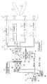
図1はこの発明の実施の形態1に係る光制御型フェーズドアレーアンテナ装置を示すブロック構成図である。
図1において、光制御型フェーズドアレーアンテナ装置は、第1および第2のマイクロ波変調光源10、20と、第1および第2のマイクロ波信号を個別に取り込む第1および第2のマイクロ波信号入力端子14、24とを備えている。
Embodiment 1.
FIG. 1 is a block diagram showing an optical control type phased array antenna apparatus according to Embodiment 1 of the present invention.
In FIG. 1, the optically controlled phased array antenna apparatus includes first and second microwave modulated
また、光制御型フェーズドアレーアンテナ装置は、第1および第2の信号光ビーム出射装置15、25と、空間光位相変調器30と、空間光位相変調器コントローラ31と、第1および第2のローカル光ビーム出射装置41、43と、光ビーム合成器50と、レンズアレー53と、光ファイバアレー54と、複数の光電変換器55と、複数のアンテナ素子からなるアレーアンテナ56とを備えている。
The optically controlled phased array antenna device includes first and second signal light
第1のマイクロ波変調光源10は、第1のマイクロ波信号入力端子14を介して入力された第1のマイクロ波信号の周波数だけ周波数偏移した第1の信号光と第1のローカル光とからなる2つのレーザ光を出力する。
同様に、第2のマイクロ波変調光源20は、第2のマイクロ波信号入力端子24を介して入力された第2のマイクロ波信号の周波数だけ周波数偏移した第2の信号光と第2のローカル光とからなる2つのレーザ光を出力する。
The first microwave modulated
Similarly, the second microwave
第1の信号光ビーム出射装置15は、第1の信号光を所定のビーム幅に変換して第1の信号光ビーム16として空間に出射する。
同様に、第2の信号光ビーム出射装置25は、第2の信号光を所定のビーム幅に変換して第2の信号光ビーム26として空間に出射する。
第1の信号光ビーム16と第2の信号光ビーム26はそれぞれ、光軸が平行であり、オフセットされ出射する。
空間光位相変調器30は、空間光位相変調器コントローラ31の制御下で機能し、異なる領域に入力された第1および第2の信号光ビーム16、26を、空間的に分離して位相変調し、所望の位相分布に変換する。
The first signal light
Similarly, the second signal light
Each of the first
The spatial
第1のローカル光ビーム出射装置41は、第1のローカル光を所定のビーム幅に変換して第1のローカル光ビーム42として空間に出射する。
同様に、第2のローカル光ビーム出射装置43は、第2のローカル光を所定のビーム幅に変換して第2のローカル光ビーム44として空間に出射する。
第1のローカル光ビーム42と第2のローカル光ビーム44はそれぞれ、光軸が平行であり、オフセットされ出射する。
The first local light
Similarly, the second local light
The first
光ビーム合成器50は、空間光位相変調器30を介して出射された第1の信号光ビーム17を透過し、第1のローカル光ビーム出射装置41から出射された第1のローカル光ビーム42を反射して、第1の信号光ビーム17と第1のローカル光ビーム42とを同軸の光路に変換して第1の合成ビーム光B1を出射する。
また、光ビーム合成器50は、空間光位相変調器30を介して出射された第2の信号光ビーム27を透過し、第2のローカル光ビーム出射装置43から出射された第2のローカル光ビーム44を反射して、第2の信号光ビーム27と第2のローカル光ビーム出射装置43とを同軸の光路に変換して第2の合成ビーム光B2を出射する。
The light beam combiner 50 transmits the first
The light beam combiner 50 transmits the second
光ファイバアレー54は、光ビーム合成器50から出射された第1および第2の合成ビーム光B1、B2を空間的にサンプリングする。
第1の合成ビーム光B1をサンプリングした第1の光ファイバアレー54aの各光ファイバと、第2の合成ビーム光B2をサンプリングした第2の光ファイバアレーの各光ファイバ54bとを光結合し、各ファイバ毎に同一の光ファイバに入れるための光カップラ70とを備える。各光カップラ70から出力した第1および第2の合成光は各々の光ファイバに接続された、光電変換器55でのヘテロダイン検波により第1のマイクロ波信号と、第2のマイクロ波信号に変換される。
第1の信号光およびおよびローカル光の波長帯f1と、第2の信号光およびローカル光の波長帯f2に、異なる波長帯を使用することにより、光カップラ70として例えば既に実用化されているアレイ導波路回折格子(AWG: Arrayed Waveguide Grating)などが適用可能である。
複数の光電変換器55は、光ファイバアレー54の各光ファイバで受光した第1および第2の合成ビーム光B1、B2をヘテロダイン検波によりマイクロ波信号に変換する。
アレーアンテナ56は、第1のマイクロ波ビーム61、および第2のマイクロ波ビーム62を形成する、複数の光電変換器55から出力されたマイクロ波信号を空間に放射する。
The
Optically coupling each optical fiber of the first optical fiber array 54a sampled from the first combined beam light B1 and each optical fiber 54b of the second optical fiber array sampled from the second combined beam light B2, Each fiber is provided with an optical coupler 70 for entering the same optical fiber. The first and second combined lights output from each optical coupler 70 are converted into a first microwave signal and a second microwave signal by heterodyne detection in a
By using different wavelength bands for the first signal light and local light wavelength band f1 and the second signal light and local light wavelength band f2, for example, an array that has already been put into practical use as the optical coupler 70. A waveguide diffraction grating (AWG: Arrayed Waveguide Grating) or the like is applicable.
The plurality of
The array antenna 56 radiates the microwave signals output from the plurality of
次に、図1に示したこの発明の実施の形態1に係る光制御型フェーズドアレーアンテナ装置の動作について説明する。
まず、第1のマイクロ波変調光源10は、連続波(CW)光からなる第1のローカル光と、第1のローカル光に対して第1のマイクロ波信号の周波数だけ周波数がオフセットされた第1の信号光との2成分のレーザ光を出力する。
同様に、第2のマイクロ波変調光源20は、連続波(CW)光からなる第2のローカル光と、第2のローカル光に対して第2のマイクロ波信号の周波数だけ周波数がオフセットされた第2の信号光との2成分のレーザ光を出力する。
Next, the operation of the optical control type phased array antenna apparatus according to Embodiment 1 of the present invention shown in FIG. 1 will be described.
First, the first microwave-modulated
Similarly, the frequency of the second microwave modulated
このようなマイクロ波変調光源10、20は、たとえば、レーザ、Mach−Zehnder型光変調器(MZ変調器)、光波長フィルタなどを組み合わせることにより実現することができる。すなわち、レーザから出射されたCW光をMZ変調器で変調することにより、CW光に対してマイクロ波周波数だけオフセットされた側帯波が生成される。この側帯波とCW光とを光波長フィルタで分離させることにより、信号光とローカル光とからなる2光波を出力させることができる。
Such microwave
各マイクロ波変調光源10、20からの第1および第2の信号光は、それぞれ、光ファイバやレンズなどで構成された第1および第2の信号光ビーム出射装置15、25を介して、所定のビーム幅の信号光ビーム16、26に変換され、空間光位相変調器30上の異なる領域に入力される。
The first and second signal lights from the microwave modulated
空間光位相変調器30上の異なる領域に入力された第1および第2の信号光ビーム16、26は、それぞれ、空間光位相変調器コントローラ31からの制御信号に応じて空間的に位相が変調され、所望の空間位相分布に変換された信号光ビーム17および27として空間光位相変調器30から出射される。なお、空間光位相変調器30としては、たとえば液晶素子などが適用される。
空間光位相変調器30から出射された第1、第2の信号光ビーム17、27は、光ビーム合成器50を介して、後述するように第1および第2の合成ビーム光B1、B2となり、光ファイバアレー54に入射される。
The first and second
The first and second
一方、各マイクロ波変調光源10、20から出射された第1および第2のローカル光は、それぞれ、光ファイバやレンズなどで構成される第1および第2のローカル光ビーム出射装置41、43を介して、所定のビーム幅の第1および第2のローカル光ビーム42、44に変換される。
On the other hand, the first and second local light beams emitted from the microwave
第1のおよび第2のローカル光ビーム42、44は、光ビーム合成器50において、それぞれ、第1および第2の信号光ビーム17、27と空間的に重ね合わされ、各信号光ビーム17、27とともに第1および第2の合成ビーム光B1、B2に変換され、光ファイバアレー54に入射されて空間的にサンプリングされる。
ここで、第1のローカル光ビーム42は、第1の信号光ビーム17と重ね合わされ、第2のローカル光ビーム44は、第2の信号光ビーム27と重ね合わされる。
The first and second local light beams 42 and 44 are spatially superimposed on the first and second signal light beams 17 and 27 in the
Here, the first
なお、ここでは、光ファイバアレー54(54a、54b)の入射端側にレンズアレー53を設け、光ファイバアレー54を構成する各光ファイバへの入力光の結合効率を高めているが、光ファイバアレー54に入射される第1および第2の合成ビーム光B1、B2の光量が十分な場合には、レンズアレー53を省略してもよい。
Here, a lens array 53 is provided on the incident end side of the optical fiber array 54 (54a, 54b) to increase the coupling efficiency of input light to each optical fiber constituting the
光ファイバアレー54内の各光ファイバに入射された第1および第2の合成ビーム光B1、B2(信号光およびローカル光)は、各光ファイバ中を伝搬し、第1の光ファイバアレー54aの各光ファイバ中を伝搬する第1の合成ビーム光と第2の光ファイバアレー54bの各光ファイバ中を伝搬する第2の合成ビーム光とが光カップラー70を介して結合される。各光カップラー70による結合光は、光ファイバを介して各光カップラー70の後段に接続された各光電変換器55に入力される。
各光電変換器55に入力された第1および第2の合成ビーム光B1、B2は、ヘテロダイン検波によりマイクロ波信号に変換されて出力される。
各光電変換器55から出力されたマイクロ波信号は、アレーアンテナ56内の各アンテナ素子に入力され、第1および第2のマイクロ波ビーム61、62となって空間に放射される。
The first and second combined beam lights B1 and B2 (signal light and local light) incident on each optical fiber in the
The first and second combined beam lights B1 and B2 input to each
The microwave signal output from each
なお、各光電変換器55とアレーアンテナ56内のアンテナ素子との間には、マイクロ波信号の強度を調整するための増幅器や減衰器などを設けてもよく、また、信号帯域を制限するための帯域フィルタなどを設けてもよい。
An amplifier or an attenuator for adjusting the intensity of the microwave signal may be provided between each
次に、各光電変換器55から出力されるマイクロ波信号について具体的に説明する。
ここで、光電変換器55に入力された信号光Sの周波数をfS1、ローカル光Lの周波数をfL1とする。ただし、|fL1−fS1|は、第1または第2のマイクロ波信号の周波数(fm1)である。
Next, the microwave signal output from each
Here, the frequency of the signal light S input to the
空間光位相変調器30による各信号光ビーム16、26への位相変調量をφ1とすると、各光電変換器55に入力される信号光Sおよびローカル光L(第1および第2の合成ビーム光B1、B2に含まれる)は、以下の式(1)、式(2)で表される。
Assuming that the phase modulation amount of each of the signal light beams 16 and 26 by the spatial
S=cos{2π(fs1)t+φ1} ・・・(1)
L=cos{2π(fL1)t}
=cos{2π(fs1−fm1)t} ・・・(2)
S = cos {2π (fs1) t + φ1} (1)
L = cos {2π (fL1) t}
= Cos {2π (fs1-fm1) t} (2)
ただし、式(1)、式(2)において、振幅は「1」、初期位相は「0」とする。
各光電変換器55からは、以下の式(3)のように表される上記2つの成分の差Dが出力される。
However, in Equation (1) and Equation (2), the amplitude is “1” and the initial phase is “0”.
Each
D=cos{2π(fs1)t+φ1}−cos{2π(fs1−fm1)t}
=cos(2π(fm1)t+φ1) ・・・(3)
D = cos {2π (fs1) t + φ1} −cos {2π (fs1−fm1) t}
= Cos (2π (fm1) t + φ1) (3)
このように、光電変換器55においては、各マイクロ波変調光源10、20に入力されるマイクロ波信号の周波数fm1に基づき、空間光位相変調器30で変調した位相量φ1のマイクロ波信号が生成される。
したがって、アレーアンテナ56の各アンテナ素子に給電されるマイクロ波信号の位相分布は、空間光位相変調器30で変調した位相分布と同一となる。
As described above, the
Therefore, the phase distribution of the microwave signal fed to each antenna element of the array antenna 56 is the same as the phase distribution modulated by the spatial
以上のように、この発明の実施の形態1(図1)によれば、第1の信号光および第2の信号光を空間的に分離して、空間光位相変調器30により別々の領域で位相変調を行い、位相変調された第1の信号光ビーム17と第1のローカル光ビーム42との第1の合成ビーム光B1が入射される光ファイバ、光電変換器およびアンテナ素子と、位相変調された第2の信号光ビーム27と第2のローカル光ビーム44との第2の合成ビーム光B2が入射される光ファイバを、各ファイバ毎に同一の光ファイバに入れるための光カップラー70で合成し、各々のファイバに接続された光電変換器およびアンテナ素子で第1のマイクロ波信号と、第2のマイクロ波信号に変換するため、1つのアレーアンテナ56を共用し、第1および第2の合成ビーム光B1、B2をそれぞれ独立に制御することが可能となる。
As described above, according to the first embodiment (FIG. 1) of the present invention, the first signal light and the second signal light are spatially separated and separated by the spatial
したがって、アレーアンテナ56により第1のマイクロ波ビーム61、および第2のマイクロ波ビーム62を形成することができる。
Therefore, the first microwave beam 61 and the
このように、空間光位相変調器30内の異なる領域で、第1および第2の信号光ビーム16、26の位相分布を独立に制御し、それぞれの信号光ビーム16、26を光カップラ70で合成し、各々のファイバに接続された光電変換器およびアンテナ素子で第1のマイクロ波信号と、第2のマイクロ波信号に変換することにより、アレーアンテナ56から複数(第1および第2)のマイクロ波ビーム61、62を放射させ、かつ複数のマイクロ波ビーム61、62を独立にアンテナ素子毎の励振振幅位相制御することが可能となる。
In this way, the phase distribution of the first and second signal light beams 16 and 26 is independently controlled in different regions in the spatial
かくして、ビームフォーミングネットワーク(BFN)に光技術を適用した光制御型マルチビームアンテナ装置において、マルチビームを容易に形成することができる
この際、1つの空間光位相変調器エリアをマルチビームのビーム毎に分割することにより、1つの空間光位相変調器で各ビーム毎に異なる位相設定が可能となり、各ビーム毎に異なる位相分布制御が可能であり、柔軟なビーム形成が可能となる。
また、1つの空間光位相変調器エリアをマルチビームのビーム毎に分割することにより、1つの空間光位相変調器でマルチビームが形成可能であり、BFNの小型化、軽量化、簡略化が可能となる。
Thus, a multi-beam can be easily formed in an optically controlled multi-beam antenna device applying optical technology to a beam forming network (BFN). At this time, one spatial light phase modulator area is provided for each beam of the multi-beam. By dividing into two, it is possible to set different phases for each beam with one spatial light phase modulator, and to control phase distribution different for each beam, so that flexible beam formation is possible.
In addition, by dividing one spatial light phase modulator area for each multi-beam, it is possible to form a multi-beam with one spatial light phase modulator, and to reduce the size, weight and simplification of BFN. It becomes.
実施の形態2.
上記実施の形態1(図1)では,信号光ビーム側のみに空間光位相変調器30を設けたが、 図2のように、ローカル光ビーム側に空間光強度変調器32を設ける。
図2はこの発明の実施の形態2に係る光制御型フェーズドアレーアンテナ装置を示すブロック構成図であり、前述(図1参照)と同様のものについては、前述と同一符号を付して詳述を省略する。
Embodiment 2.
In the first embodiment (FIG. 1), the spatial
2 is a block diagram showing an optical control type phased array antenna apparatus according to Embodiment 2 of the present invention. The same components as those described above (see FIG. 1) are denoted by the same reference numerals as those described above and described in detail. Is omitted.
図2においては、前述(図1)の構成に加えて、空間光強度変調器32と空間光強度変調器コントローラ33とが設けられている。
すなわち、第1および第2のローカル光ビーム出射装置41、43と光ビーム合成器50との間には、空間光強度変調器コントローラ33の制御下で機能する空間光強度変調器32が挿入されている。
空間光強度変調器32は、異なる領域に入力された第1および第2のローカル光ビーム42、44を強度変調し、所望の空間強度分布に変換した第1および第2のローカル光ビーム45、46として出射する。
2, in addition to the configuration described above (FIG. 1), a spatial
That is, the spatial
The spatial
次に、図2に示したこの実施の形態2に係る光制御型フェーズドアレーアンテナ装置の動作について説明する。
前述と同様に、第1および第2のマイクロ波変調光源10、20から出射された第1および第2のローカル光は、第1および第2のローカル光ビーム出射装置41、43を介して所定のビーム幅に変換され、第1および第2のローカル光ビーム42、44となる。
Next, the operation of the optically controlled phased array antenna device according to Embodiment 2 shown in FIG. 2 will be described.
Similarly to the above, the first and second local lights emitted from the first and second microwave modulated
続いて、第1および第2のローカル光ビーム42、44は、空間光強度変調器32上の異なる領域に入力される。
空間光強度変調器32は、空間光強度変調器コントローラ33からの制御信号に応じて、第1および第2のローカル光ビーム42、44を空間的に強度変調し、所望の空間強度分布に変換されたローカル光ビーム45および46として出射する。
なお、空間光強度変調器32としては、空間光位相変調器30と同様に、液晶素子などが適用され得る。
Subsequently, the first and second local light beams 42 and 44 are input to different regions on the spatial
The spatial
As the spatial
以下、空間光強度変調器32から出射された第1、第2のローカル光ビーム45、46は、前述の実施の形態1と同様に、光ビーム合成器50に入射され、それぞれ、第1および第2の信号光ビーム17、27と空間的に合成されて、第1および第2の合成ビーム光B1、B2となり、光ファイバアレー54において空間的にサンプリングされる。
Thereafter, the first and second local light beams 45 and 46 emitted from the spatial
第1の合成ビーム光B1をサンプリングした第1の光ファイバアレーの各光ファイバと、第2の合成ビーム光B2をサンプリングした第2の光ファイバアレーの各光ファイバとを、各ファイバ毎に同一の光ファイバに入れるための光カップラ70とを備え、各光カップラ70から出力した第1および第2の合成光は各々のファイバに接続された、光電変換器でのヘテロダイン検波により第1のマイクロ波信号と、第2のマイクロ波信号に変換される。
第1の信号光およびおよびローカル光の波長帯と、第2の信号光およびローカル光の波長帯に、異なる波長帯を使用することにより、光カップラ70として例えば既に実用化されているアレイ導波路回折格子(AWG: Arrayed Waveguide Grating)などが適用可能である。
このとき、各光電変換器55で生成されるマイクロ波信号の強度は、信号光とローカル光との強度の積となるので、空間光強度変調器32によりローカル光ビーム45、46の強度分布を制御することによりマイクロ波信号の強度を制御することができる。
Each optical fiber of the first optical fiber array that samples the first combined beam light B1 and each optical fiber of the second optical fiber array that samples the second combined beam light B2 are the same for each fiber. The first and second combined lights output from each optical coupler 70 are connected to the respective fibers by the heterodyne detection by the photoelectric converter, and are coupled to the first microcoupler. Converted into a wave signal and a second microwave signal.
By using different wavelength bands for the first signal light and local light wavelength bands and the second signal light and local light wavelength bands, for example, an array waveguide that has already been put into practical use as the optical coupler 70. A diffraction grating (AWG: Arrayed Waveguide Grating) or the like is applicable.
At this time, since the intensity of the microwave signal generated by each
これにより、アレーアンテナ56の各アンテナ素子に給電されるマイクロ波信号の強度分布が制御可能となるので、第1および第2のアンテナ放射ビーム61、62のサイドローブ制御、ビーム幅制御など、ビーム形状に対する柔軟性をアンテナ素子毎の励振振幅位相制御により向上させることができる。 As a result, the intensity distribution of the microwave signal fed to each antenna element of the array antenna 56 can be controlled, so that the side lobe control and beam width control of the first and second antenna radiation beams 61 and 62 can be performed. Flexibility with respect to shape can be improved by excitation amplitude phase control for each antenna element.
かくして、ビームフォーミングネットワーク(BFN)に光技術を適用した光制御型マルチビームアンテナ装置であり、マルチビームを容易に形成することが可能となる。
また、1つの空間光振幅変調器エリアをマルチビームのビーム毎に分割することにより、1つの空間光振幅変調器で各ビーム毎に異なる振幅設定が可能となり、各ビーム毎に異なる振幅分布制御が可能であり、柔軟なビーム形成が可能となる。
さらに、1つの空間光振幅変調器エリアをマルチビームのビーム毎に分割することにより、1つの空間光振幅変調器でマルチビームが形成可能であり、BFNの小型化、軽量化、簡略化が可能となる。
Thus, the optical control type multi-beam antenna device applying the optical technology to the beam forming network (BFN) can easily form multi-beams.
In addition, by dividing one spatial light amplitude modulator area for each beam of multi-beams, it is possible to set different amplitudes for each beam with one spatial light amplitude modulator, and different amplitude distribution control for each beam. It is possible and flexible beam forming is possible.
Furthermore, by dividing one spatial light amplitude modulator area for each multi-beam, a single spatial light amplitude modulator can form a multi-beam, and the BFN can be made smaller, lighter and simplified. It becomes.
なお、上記実施の形態1、2では、2つのマイクロ波変調光源10、20を用いて2つの光ビームを発生させたが、3つ以上のマイクロ波変調光源(図示せず)を用いて、図1および図2と同様に空間光位相変調器30、空間光強度変調器32を3つ以上の空間に分割して、それぞれの合成ビーム光を光カップラー70で合成し、光電変換器55でそれぞれのマイクロ波信号に変換し、アレーアンテナ56から放射することにより、3つ以上のマルチビームを実現可能なことは言うまでもない。
In the first and second embodiments, two light beams are generated using the two microwave
また、透過型の空間光位相変調器30および空間光強度変調器32を用いたが、それぞれ、反射型の空間光変調器を用いてもよく、前述と同等の作用効果を奏することは言うまでもない。
さらに、空間光位相変調器30、空間光強度変調器32およびアレーアンテナ56などを1次元方向(図1、図2中の縦方向)に分割した例を示したが、2次元的に分割しても良いことは言うまでもない。
Further, although the transmissive spatial
Furthermore, although an example in which the spatial
10 第1のマイクロ波変調光源(第1の光源)、20 第2のマイクロ波変調光源(第2の光源)、14 第1のマイクロ波信号入力端子、24 第2のマイクロ波信号入力端子、15 第1の信号光ビーム出射装置、25 第2の信号光ビーム出射装置、16、17 第1の信号光ビーム、26、27 第2の信号光ビーム、30 空間光位相変調器、31 空間光位相変調器コントローラ、32 空間光強度変調器、33 空間光強度変調器コントローラ、41 第1のローカル光ビーム出射装置、43 第2のローカル光ビーム出射装置、42、45 第1のローカル光ビーム、44、46 第2のローカル光ビーム、50 光ビーム合成器、B1 第1の合成ビーム光、B2 第2の合成ビーム光、54 光ファイバアレー、55 光電変換器、56 アレーアンテナ、70 光カップラー。 10 first microwave modulated light source (first light source), 20 second microwave modulated light source (second light source), 14 first microwave signal input terminal, 24 second microwave signal input terminal, 15 First signal light beam emitting device, 25 Second signal light beam emitting device, 16, 17 First signal light beam, 26, 27 Second signal light beam, 30 Spatial light phase modulator, 31 Spatial light Phase modulator controller, 32 spatial light intensity modulator, 33 spatial light intensity modulator controller, 41 first local light beam emitting device, 43 second local light beam emitting device, 42, 45 first local light beam, 44, 46 second local light beam, 50 light beam combiner, B1 first combined beam light, B2 second combined beam light, 54 optical fiber array, 55 photoelectric converter, 6 array antenna, 70 light couplers.
Claims (3)
第2の信号光および第1のローカル光を出力する第2の光源と、
各信号光のビームを位相変調する空間光位相変調器と、
上記空間光位相変調器により位相変調された第1の信号光と第1のローカル光とから第1の合成ビーム光を出射し、上記空間光位相変調器により位相変調された第2の信号光と第2のローカル光とから第2の合成ビーム光を出射する光ビーム合成器と、
上記光ビーム合成器により合成されたそれぞれのビーム光を同一の光ファイバアレーに結合する光カップラーと、
を備えた光制御型マルチビームアンテナ装置。 A first light source that outputs a first signal light and a first local light;
A second light source that outputs a second signal light and a first local light;
A spatial light phase modulator that phase modulates the beam of each signal light;
The first combined beam light is emitted from the first signal light phase-modulated by the spatial light phase modulator and the first local light, and the second signal light phase-modulated by the spatial light phase modulator. A light beam combiner that emits a second combined beam light from the second local light; and
An optical coupler that couples the light beams synthesized by the light beam combiner to the same optical fiber array;
An optical control type multi-beam antenna device comprising:
ローカル光を出力する第1のマイクロ波変調光源と、
第2のマイクロ波信号の周波数分だけ互いに周波数偏移した第2の信号光および第2の
ローカル光を、上記第1の信号光および第1のローカル光とは異なる光波長帯で出力する第2のマイクロ波変調光源と、
上記第1、第2の信号光が異なる領域にそれぞれ入射され、空間的に分離して位相変調する空間光位相変調器と、
上記空間位相変調器により位相変調された第1の信号光と第1のローカル光を合成した第1の合成ビームを出力し、上記空間位相変調器により位相変調された第2の信号光と第2のローカル光を合成した第2の合成ビームを出力する光ビーム合成器と、
上記光ビーム合成器により合成された第1の合成ビームが複数の光ファイバに分離されてそれぞれ結合される複数の第1の光ファイバアレーと、
上記光ビーム合成器により合成された第2の合成ビームが複数の光ファイバに分離されてそれぞれ結合される複数の第2の光ファイバアレーと、
上記それぞれの第1、第2の光ファイバアレーがそれぞれ有する光ファイバを光結合する複数の光カップラーと、
上記それぞれの光カップラーにより結合された結合光を光電変換する光電変換器と、
上記それぞれの光電変換器により光電変換されたマイクロ波信号が給電され、空間に電波を放射する、アレーアンテナを構成する複数のアンテナ素子と、
を備えた光制御型マルチビームアンテナ装置。 A first microwave modulated light source that outputs a first signal light and a first local light that are frequency-shifted from each other by the frequency of the first microwave signal;
The second signal light and the second local light that are shifted in frequency by the frequency of the second microwave signal are output in an optical wavelength band different from that of the first signal light and the first local light. Two microwave modulated light sources;
A spatial light phase modulator that the first and second signal lights are respectively incident on different regions and spatially separated and phase-modulated;
A first combined beam obtained by combining the first signal light phase-modulated by the spatial phase modulator and the first local light is output, and the second signal light phase-modulated by the spatial phase modulator and the second signal light A light beam combiner that outputs a second combined beam obtained by combining the two local lights;
A plurality of first optical fiber arrays in which the first combined beam combined by the light beam combiner is separated into a plurality of optical fibers and respectively coupled;
A plurality of second optical fiber arrays in which the second combined beams combined by the light beam combiner are separated into a plurality of optical fibers and respectively coupled;
A plurality of optical couplers for optically coupling optical fibers included in each of the first and second optical fiber arrays;
A photoelectric converter that photoelectrically converts the combined light combined by each of the optical couplers;
A plurality of antenna elements constituting an array antenna, which are fed with microwave signals photoelectrically converted by the respective photoelectric converters and radiate radio waves into space,
An optical control type multi-beam antenna device comprising:
ローカル光を出力する第1のマイクロ波変調光源と、
第2のマイクロ波信号の周波数分だけ互いに周波数偏移した第2の信号光および第2の
ローカル光を、上記第1の信号光および第1のローカル光とは異なる光波長帯で出力する第2のマイクロ波変調光源と、
上記第1、第2の信号光が異なる領域にそれぞれ入射され、空間的に分離して位相変調する第1の空間光位相変調器と、
上記第1、第2のローカル光が異なる領域にそれぞれ入射され、空間的に分離して強度変調する第2の空間光強度変調器と、
上記第1の空間位相変調器により位相変調された第1の信号光と第2の空間強度変調器により強度変調された第1のローカル光を合成した第1の合成ビームを出力し、第1の空間位相変調器により位相変調された第2の信号光と第2の空間強度変調器により強度変調された第2のローカル光を合成した第2の合成ビームを出力する光ビーム合成器と、
上記光ビーム合成器により合成された第1の合成ビームが複数の光ファイバに分離されてそれぞれ結合される複数の第1の光ファイバアレーと、
上記光ビーム合成器により合成された第2の合成ビームが複数の光ファイバに分離されてそれぞれ結合される複数の第2の光ファイバアレーと、
上記それぞれの第1、第2の光ファイバアレーがそれぞれ有する光ファイバを光結合する複数の光カップラーと、
上記それぞれの光カップラーにより結合された結合光を光電変換する光電変換器と、
上記それぞれの光電変換器により光電変換されたマイクロ波信号が給電され、空間に電波を放射する複数のアンテナ素子と、
を備えた光制御型マルチビームアンテナ装置。 A first microwave modulated light source that outputs a first signal light and a first local light that are frequency-shifted from each other by the frequency of the first microwave signal;
The second signal light and the second local light that are shifted in frequency by the frequency of the second microwave signal are output in an optical wavelength band different from that of the first signal light and the first local light. Two microwave modulated light sources;
A first spatial light phase modulator in which the first and second signal lights are respectively incident on different regions and spatially separated and phase modulated;
A second spatial light intensity modulator that the first and second local lights are respectively incident on different regions and spatially separated and intensity-modulated;
A first combined beam obtained by combining the first signal light phase-modulated by the first spatial phase modulator and the first local light intensity-modulated by the second spatial intensity modulator; A light beam synthesizer that outputs a second combined beam obtained by combining the second signal light phase-modulated by the spatial phase modulator and the second local light intensity-modulated by the second spatial intensity modulator;
A plurality of first optical fiber arrays in which the first combined beam combined by the light beam combiner is separated into a plurality of optical fibers and respectively coupled;
A plurality of second optical fiber arrays in which the second combined beams combined by the light beam combiner are separated into a plurality of optical fibers and respectively coupled;
A plurality of optical couplers for optically coupling optical fibers included in each of the first and second optical fiber arrays;
A photoelectric converter that photoelectrically converts the combined light combined by each of the optical couplers;
A plurality of antenna elements that are fed with microwave signals photoelectrically converted by the respective photoelectric converters and radiate radio waves into space,
An optical control type multi-beam antenna device comprising:
Priority Applications (1)
| Application Number | Priority Date | Filing Date | Title |
|---|---|---|---|
| JP2008184187A JP5067291B2 (en) | 2008-07-15 | 2008-07-15 | Optically controlled multi-beam antenna device |
Applications Claiming Priority (1)
| Application Number | Priority Date | Filing Date | Title |
|---|---|---|---|
| JP2008184187A JP5067291B2 (en) | 2008-07-15 | 2008-07-15 | Optically controlled multi-beam antenna device |
Publications (2)
| Publication Number | Publication Date |
|---|---|
| JP2010028236A true JP2010028236A (en) | 2010-02-04 |
| JP5067291B2 JP5067291B2 (en) | 2012-11-07 |
Family
ID=41733686
Family Applications (1)
| Application Number | Title | Priority Date | Filing Date |
|---|---|---|---|
| JP2008184187A Expired - Fee Related JP5067291B2 (en) | 2008-07-15 | 2008-07-15 | Optically controlled multi-beam antenna device |
Country Status (1)
| Country | Link |
|---|---|
| JP (1) | JP5067291B2 (en) |
Cited By (6)
| Publication number | Priority date | Publication date | Assignee | Title |
|---|---|---|---|---|
| WO2014110017A1 (en) * | 2013-01-08 | 2014-07-17 | Massachusetts Institute Of Technology | Optical phased arrays |
| CN114336257A (en) * | 2021-12-30 | 2022-04-12 | 中国人民解放军国防科技大学 | Precise phase control method of all-fiber laser phased array system |
| US11372106B2 (en) | 2013-01-08 | 2022-06-28 | Massachusetts Institute Of Technology | Optical phased arrays |
| WO2023242932A1 (en) * | 2022-06-13 | 2023-12-21 | 日本電信電話株式会社 | Transmission directivity control device and transmission directivity control method |
| WO2023242931A1 (en) * | 2022-06-13 | 2023-12-21 | 日本電信電話株式会社 | Transmission directivity control device and transmission directivity control method |
| CN114336257B (en) * | 2021-12-30 | 2024-04-23 | 中国人民解放军国防科技大学 | Accurate phase control method of all-fiber laser phased array system |
Citations (10)
| Publication number | Priority date | Publication date | Assignee | Title |
|---|---|---|---|---|
| JPH01212004A (en) * | 1988-02-18 | 1989-08-25 | A T R Koudenpa Tsushin Kenkyusho:Kk | Opticaly controlled phased array antenna |
| JPH06276017A (en) * | 1993-03-22 | 1994-09-30 | Nippon Telegr & Teleph Corp <Ntt> | Antenna feeding circuit |
| JPH09215048A (en) * | 1996-02-06 | 1997-08-15 | Nippon Telegr & Teleph Corp <Ntt> | Optical link for radio signal transmission |
| JPH10233615A (en) * | 1997-02-19 | 1998-09-02 | Atr Kankyo Tekiou Tsushin Kenkyusho:Kk | Optically controlled phased array antenna |
| JP2002299942A (en) * | 2001-03-29 | 2002-10-11 | Communication Research Laboratory | Phase controller of optical control phased array antenna and optical control phased array antenna system |
| JP2003347826A (en) * | 2002-05-29 | 2003-12-05 | Mitsubishi Electric Corp | Optically controlled phased array antenna |
| WO2005004324A1 (en) * | 2003-07-04 | 2005-01-13 | Mitsubishi Denki Kabushiki Kaisha | Optical control type microwave phase forming device |
| JP2005354388A (en) * | 2004-06-10 | 2005-12-22 | Mitsubishi Electric Corp | Light control type phased array antenna system |
| JP2007158570A (en) * | 2005-12-02 | 2007-06-21 | Mitsubishi Electric Corp | Optically controlled reflection mirror antenna device |
| JP2007174377A (en) * | 2005-12-22 | 2007-07-05 | Mitsubishi Electric Corp | Optical control type array antenna apparatus |
-
2008
- 2008-07-15 JP JP2008184187A patent/JP5067291B2/en not_active Expired - Fee Related
Patent Citations (10)
| Publication number | Priority date | Publication date | Assignee | Title |
|---|---|---|---|---|
| JPH01212004A (en) * | 1988-02-18 | 1989-08-25 | A T R Koudenpa Tsushin Kenkyusho:Kk | Opticaly controlled phased array antenna |
| JPH06276017A (en) * | 1993-03-22 | 1994-09-30 | Nippon Telegr & Teleph Corp <Ntt> | Antenna feeding circuit |
| JPH09215048A (en) * | 1996-02-06 | 1997-08-15 | Nippon Telegr & Teleph Corp <Ntt> | Optical link for radio signal transmission |
| JPH10233615A (en) * | 1997-02-19 | 1998-09-02 | Atr Kankyo Tekiou Tsushin Kenkyusho:Kk | Optically controlled phased array antenna |
| JP2002299942A (en) * | 2001-03-29 | 2002-10-11 | Communication Research Laboratory | Phase controller of optical control phased array antenna and optical control phased array antenna system |
| JP2003347826A (en) * | 2002-05-29 | 2003-12-05 | Mitsubishi Electric Corp | Optically controlled phased array antenna |
| WO2005004324A1 (en) * | 2003-07-04 | 2005-01-13 | Mitsubishi Denki Kabushiki Kaisha | Optical control type microwave phase forming device |
| JP2005354388A (en) * | 2004-06-10 | 2005-12-22 | Mitsubishi Electric Corp | Light control type phased array antenna system |
| JP2007158570A (en) * | 2005-12-02 | 2007-06-21 | Mitsubishi Electric Corp | Optically controlled reflection mirror antenna device |
| JP2007174377A (en) * | 2005-12-22 | 2007-07-05 | Mitsubishi Electric Corp | Optical control type array antenna apparatus |
Cited By (7)
| Publication number | Priority date | Publication date | Assignee | Title |
|---|---|---|---|---|
| WO2014110017A1 (en) * | 2013-01-08 | 2014-07-17 | Massachusetts Institute Of Technology | Optical phased arrays |
| US8988754B2 (en) | 2013-01-08 | 2015-03-24 | Massachusetts Institute Of Technology | Optical phased arrays with evanescently-coupled antennas |
| US11372106B2 (en) | 2013-01-08 | 2022-06-28 | Massachusetts Institute Of Technology | Optical phased arrays |
| CN114336257A (en) * | 2021-12-30 | 2022-04-12 | 中国人民解放军国防科技大学 | Precise phase control method of all-fiber laser phased array system |
| CN114336257B (en) * | 2021-12-30 | 2024-04-23 | 中国人民解放军国防科技大学 | Accurate phase control method of all-fiber laser phased array system |
| WO2023242932A1 (en) * | 2022-06-13 | 2023-12-21 | 日本電信電話株式会社 | Transmission directivity control device and transmission directivity control method |
| WO2023242931A1 (en) * | 2022-06-13 | 2023-12-21 | 日本電信電話株式会社 | Transmission directivity control device and transmission directivity control method |
Also Published As
| Publication number | Publication date |
|---|---|
| JP5067291B2 (en) | 2012-11-07 |
Similar Documents
| Publication | Publication Date | Title |
|---|---|---|
| JP4632444B2 (en) | Optical control array antenna device | |
| JP7328578B2 (en) | Radio transmission system, radio reception system, base station apparatus, radio communication system, radio transmission method, and radio reception method | |
| JP4140734B2 (en) | Optically controlled microwave phase forming device | |
| JP5067291B2 (en) | Optically controlled multi-beam antenna device | |
| US20130202308A1 (en) | Phased antenna array including a plurality of electro-optical circuits having an optical source with an opto-electronic oscillator and associated methods | |
| US20130177319A1 (en) | Phased antenna array with electro-optic readout circuit with mll and related methods | |
| JP4475592B2 (en) | Optically controlled array antenna device | |
| KR20170010478A (en) | Optical transmitting/receiving apparatus for input/output mode control and optical transmission system using the same | |
| US20130177315A1 (en) | Phased antenna array with electro-optic readout circuit with multiplexing and mll and related methods | |
| JP4007493B2 (en) | Optically controlled phased array antenna | |
| JP4555218B2 (en) | Optically controlled reflector antenna device | |
| US8861971B2 (en) | Phased antenna array with electro-optic readout circuit with multiplexing and related methods | |
| WO2021106041A1 (en) | Wireless transmission system, wireless reception system, base station device, wireless communication system, wireless transmission method, and wireless reception method | |
| JP3009631B2 (en) | Optically controlled phased array antenna | |
| JP4524403B2 (en) | Fourier transform optical device and optically controlled phased array antenna device | |
| JP4140724B2 (en) | Optically controlled phased array antenna device | |
| JP4999732B2 (en) | Optically controlled phased array antenna device | |
| JP4937164B2 (en) | Optically controlled multi-beam antenna | |
| US20130202307A1 (en) | Phased antenna array including a plurality of electro-optical circuits spaced apart from and coupled to a plurality of antenna circuits and associated methods | |
| JP4974871B2 (en) | Antenna device | |
| JP2009239669A (en) | Optical control type phased array antenna device | |
| JP2004023400A (en) | Optical control array antenna system | |
| JP2965504B2 (en) | Optically controlled reception signal processor for array antenna | |
| JP2008271090A (en) | Optically controlled phased array antenna apparatus | |
| JP4066380B2 (en) | Optically controlled phased array antenna |
Legal Events
| Date | Code | Title | Description |
|---|---|---|---|
| A621 | Written request for application examination |
Free format text: JAPANESE INTERMEDIATE CODE: A621 Effective date: 20110526 |
|
| A977 | Report on retrieval |
Free format text: JAPANESE INTERMEDIATE CODE: A971007 Effective date: 20120702 |
|
| TRDD | Decision of grant or rejection written | ||
| A01 | Written decision to grant a patent or to grant a registration (utility model) |
Free format text: JAPANESE INTERMEDIATE CODE: A01 Effective date: 20120717 |
|
| A01 | Written decision to grant a patent or to grant a registration (utility model) |
Free format text: JAPANESE INTERMEDIATE CODE: A01 |
|
| A61 | First payment of annual fees (during grant procedure) |
Free format text: JAPANESE INTERMEDIATE CODE: A61 Effective date: 20120730 |
|
| FPAY | Renewal fee payment (event date is renewal date of database) |
Free format text: PAYMENT UNTIL: 20150824 Year of fee payment: 3 |
|
| R151 | Written notification of patent or utility model registration |
Ref document number: 5067291 Country of ref document: JP Free format text: JAPANESE INTERMEDIATE CODE: R151 |
|
| FPAY | Renewal fee payment (event date is renewal date of database) |
Free format text: PAYMENT UNTIL: 20150824 Year of fee payment: 3 |
|
| R250 | Receipt of annual fees |
Free format text: JAPANESE INTERMEDIATE CODE: R250 |
|
| R250 | Receipt of annual fees |
Free format text: JAPANESE INTERMEDIATE CODE: R250 |
|
| R250 | Receipt of annual fees |
Free format text: JAPANESE INTERMEDIATE CODE: R250 |
|
| R250 | Receipt of annual fees |
Free format text: JAPANESE INTERMEDIATE CODE: R250 |
|
| LAPS | Cancellation because of no payment of annual fees |