JP2010026487A - Developing device and image forming apparatus equipped therewith - Google Patents
Developing device and image forming apparatus equipped therewith Download PDFInfo
- Publication number
- JP2010026487A JP2010026487A JP2008334746A JP2008334746A JP2010026487A JP 2010026487 A JP2010026487 A JP 2010026487A JP 2008334746 A JP2008334746 A JP 2008334746A JP 2008334746 A JP2008334746 A JP 2008334746A JP 2010026487 A JP2010026487 A JP 2010026487A
- Authority
- JP
- Japan
- Prior art keywords
- developer
- toner
- developing device
- return blade
- transport
- Prior art date
- Legal status (The legal status is an assumption and is not a legal conclusion. Google has not performed a legal analysis and makes no representation as to the accuracy of the status listed.)
- Granted
Links
Images


Abstract
Description
本発明は、電子写真方式の画像形成装置に備えられ、トナーとキャリアとを含む2成分現像剤を取り扱う現像装置及びそれを備える画像形成装置に関するものである。 The present invention relates to a developing device that is provided in an electrophotographic image forming apparatus and handles a two-component developer containing toner and a carrier, and an image forming apparatus including the developing device.
従来から、複写機、プリンタおよびファクシミリ等の電子写真方式の画像形成装置が知られている。電子写真方式の画像形成装置は、感光体(トナー像担持体)の表面に静電潜像を形成し、現像装置によって前記静電潜像に対してトナーを供給して前記静電潜像を現像し、現像によって形成されるトナー像を用紙等のシートに転写し定着させるようになっている。 2. Description of the Related Art Conventionally, electrophotographic image forming apparatuses such as copying machines, printers, and facsimiles are known. An electrophotographic image forming apparatus forms an electrostatic latent image on the surface of a photoreceptor (toner image carrier), and supplies toner to the electrostatic latent image by a developing device to form the electrostatic latent image. Development is performed, and a toner image formed by development is transferred and fixed on a sheet such as paper.
近年、カラー化や高画質化に対応した画像形成装置では、トナーの帯電安定性に優れる2成分現像剤(以下では、単に「現像剤」と称すこともある)がよく使用されている。2成分現像剤は、トナーとキャリアとからなり、それらを現像装置内で撹拌するとトナーとキャリアとが摩擦し、この摩擦によって適正に帯電したトナーが得られる。帯電したトナーは、現像ローラ等の現像剤担持部材の表面に供給される。現像剤担持部材のトナーは、静電的吸引力によって、像担持体(感光体)に形成されている静電潜像に移動する。これにより感光体上にトナー像が形成される。 2. Description of the Related Art In recent years, two-component developers (hereinafter sometimes simply referred to as “developers”) that are excellent in toner charging stability are often used in image forming apparatuses that support colorization and high image quality. The two-component developer is composed of toner and carrier, and when they are agitated in the developing device, the toner and the carrier are rubbed, and a properly charged toner is obtained by this friction. The charged toner is supplied to the surface of a developer carrying member such as a developing roller. The toner on the developer carrying member moves to an electrostatic latent image formed on the image carrier (photosensitive member) by electrostatic attraction. As a result, a toner image is formed on the photoreceptor.
また、最近では、画像形成装置の高速化および小型化が要求されており、現像剤の帯電を迅速且つ充分に行い、現像剤の搬送も迅速に行う必要が生じてきている。 Recently, there has been a demand for speeding up and downsizing of an image forming apparatus, and it has become necessary to quickly and sufficiently charge the developer and to transport the developer quickly.
上記要求に応えるものとして、循環方式の現像装置が多用されている。循環方式の現像装置は、現像剤が循環して搬送される現像剤搬送路と、現像剤搬送路にて現像剤を撹拌しながら搬送する現像剤搬送部材とを有する。現像剤は、現像剤搬送路内を現像剤搬送部材にて撹拌されながら搬送される間に、迅速且つ充分に帯電されることとなる。 In order to meet the above requirements, a circulation type developing device is frequently used. The circulation type developing device includes a developer transport path through which the developer is circulated and transported, and a developer transport member that transports the developer while stirring the developer in the developer transport path. The developer is quickly and sufficiently charged while being transported while being stirred in the developer transport path by the developer transport member.
このような循環方式の現像装置においては、現像装置の上部にトナーホッパーが設けられており、現像装置内部の現像剤のトナー濃度が所定値よりも下回った場合、トナーホッパーから現像剤搬送路へトナーが補給されるようになっている。補給されたトナー(以下、補給トナーと称することもある)は、現像剤搬送路を搬送される間に、従前よりある現像剤と混ぜ合わされ帯電されていく。 In such a circulation type developing device, a toner hopper is provided at the upper portion of the developing device, and when the toner concentration of the developer inside the developing device falls below a predetermined value, the toner hopper is transferred to the developer conveying path. The toner is replenished. The replenished toner (hereinafter also referred to as replenishment toner) is mixed and charged with a certain developer while being conveyed through the developer conveyance path.
ところが、このような循環方式の現像装置においては、補給されたトナーが、キャリア(従前からある現像剤)と充分に混ざり合わないうち、つまり、充分に帯電されていない低帯電量の状態で、現像剤担持部材に供給されてしまうことがある。 However, in such a circulation type developing device, the replenished toner is not sufficiently mixed with the carrier (a conventional developer), that is, in a state of a low charge amount that is not sufficiently charged. It may be supplied to the developer carrying member.
充分に帯電されていないトナーが現像剤担持部材に供給されてしまうと、現像剤担持部材からトナーが飛散するという問題が生じやすくなり、画像形成装置内部や形成された画像を汚してしまう。また、充分に帯電されていないトナーが現像剤担持部材に供給されてしまうと、トナーをキャリア表面に保持するための静電気力が小さくなり、非画像部にトナーが付着しカブリが生じ易くなるという問題も生じる。 If toner that is not sufficiently charged is supplied to the developer carrying member, there is a problem that the toner is scattered from the developer carrying member, and the inside of the image forming apparatus and the formed image are stained. Further, if toner that is not sufficiently charged is supplied to the developer carrying member, the electrostatic force for holding the toner on the surface of the carrier is reduced, and the toner adheres to the non-image area and is likely to be fogged. Problems also arise.
このような問題に鑑みたものとして、特許文献1には、現像剤搬送路に、現像剤が複数回通過するメッシュ状のスクリーン部材を配する構成が記載されている。一例では、現像剤搬送部材を、回転軸の周りに送りねじり状の翼体を有するスクリューより構成し、翼体と翼体との間に、スクリーン部材が配設されている。
しかしながら、上記スクーン部材を配置した現像装置であっても、トナーホッパーから現像剤搬送路に補給されるトナー量(補給トナー量)が多く、固まった状態で、従前からある現像剤の上面(現像剤面)を搬送されてしまい、従前からある現像剤と充分に混合させることができず、充分に帯電されていない状態で現像剤担持部材に供給されるといった問題があった。 However, even in the developing device in which the scoon member is disposed, the amount of toner (supplemented toner amount) replenished from the toner hopper to the developer transport path is large and solidified, and the upper surface (development) There is a problem that the developer surface) is transported and cannot be sufficiently mixed with a certain developer, and is supplied to the developer carrying member in a state where it is not sufficiently charged.
このような問題を解決するための1つの対策として、現像剤搬送路において、現像剤の上面に形成される上部の空間を完全になくしてしまう構成が考えられる。しかしながら、このような構成では、現像剤に過度のストレスがかかり、現像剤の磨耗が促進されて現像剤寿命が短くなったり、現像剤が搬送できなくなったりする。 As one countermeasure for solving such a problem, a configuration in which the upper space formed on the upper surface of the developer is completely eliminated in the developer transport path is conceivable. However, in such a configuration, an excessive stress is applied to the developer, and the wear of the developer is promoted, so that the life of the developer is shortened or the developer cannot be conveyed.
これは、現像剤の嵩(体積)の変化に起因すると考えられる。つまり、現像剤の嵩は、現像剤中のトナー濃度やトナー帯電量の変化などにより絶えず変化するものであが、上記構成では、このような変化を吸収できる空間がなく、現像剤の内圧が高まり、その結果、現像剤に過度のストレスがかかると考えられる。 This is considered due to a change in the volume (volume) of the developer. In other words, the volume of the developer constantly changes due to changes in the toner concentration and the toner charge amount in the developer, but in the above configuration, there is no space for absorbing such changes, and the internal pressure of the developer is low. As a result, it is considered that the developer is excessively stressed.
また、トナー補給口付近において現像剤の嵩が高くなると、補給トナーがトナー補給口でブリッジを形成してしまい、トナー補給口を塞いでしまうといった問題も生じる。 In addition, when the bulk of the developer increases in the vicinity of the toner supply port, there is a problem that the supply toner forms a bridge at the toner supply port and closes the toner supply port.
本発明は、電子写真方式の画像形成装置に備えられる現像装置において、現像剤に過度のストレスを与えることなく、補給トナーが固まりとなって現像剤の上を搬送されてきたとしても、充分に帯電されていないトナーが現像剤担持部材に供給されることを効果的に抑制することができる現像装置、及びそれを備えた画像形成装置を提供することを目的とする。 According to the present invention, in a developing device provided in an electrophotographic image forming apparatus, even if replenished toner is hardened and transported on the developer without giving excessive stress to the developer, it is sufficient. It is an object of the present invention to provide a developing device capable of effectively suppressing uncharged toner from being supplied to a developer carrying member, and an image forming apparatus including the developing device.
本発明の現像装置は、上記課題を解決するために、トナーとキャリアとを含む現像剤を収容する現像槽と、該現像槽内に設けられた、前記現像剤が搬送される第1および第2搬送路と、前記第1搬送路に設けられた、第1搬送路にて前記現像剤を撹拌しながら所定方向へ搬送する第1搬送部材と、前記第2搬送路に設けられた、第2搬送路にて前記現像剤を撹拌しながら前記所定方向とは逆方向へ搬送する第2搬送部材と、前記第1および第2搬送路の端部同士を長手方向両側において連通する第1および第2連通路と、前記第2搬送路の現像剤を担持してその現像剤に含まれるトナーを感光体へ供給する現像剤担持部材と、前記第1搬送路内を搬送される前記現像剤の上面を、上部に空間を残して覆う現像槽カバーと、前記第1搬送路にトナーを補給するためのトナー補給口とを有し、前記現像剤が、前記第1搬送路、第1連通路、第2搬送路、及び第2連通路をこの順序にて循環するように搬送される現像装置において、前記第1搬送路内における前記トナー補給口の循環方向下流側に、当該第1搬送路を搬送される現像剤の上部の空間を封鎖する上部空間封鎖手段が設けられていることを特徴としている。 In order to solve the above-described problems, the developing device of the present invention includes a developing tank that stores a developer containing toner and a carrier, and a first tank and a first tank that are provided in the developing tank and transport the developer. Two conveying paths, a first conveying member provided in the first conveying path for conveying the developer in a predetermined direction while stirring the developer in the first conveying path, and a first conveying member provided in the second conveying path. A second conveying member that conveys the developer in a direction opposite to the predetermined direction while stirring the developer in the two conveying paths; and first and second ends that communicate with each other at both ends in the longitudinal direction of the first and second conveying paths. A second communication path; a developer carrying member that carries the developer in the second transport path and supplies toner contained in the developer to the photoconductor; and the developer transported in the first transport path A developer tank cover that covers the top surface of the first transport path leaving a space above the first transport path. A toner replenishing port for replenishing toner, and the developer is conveyed so as to circulate in this order in the first conveying path, the first communicating path, the second conveying path, and the second communicating path. In the developing device, an upper space blocking means for blocking the upper space of the developer conveyed along the first conveyance path is provided on the downstream side in the circulation direction of the toner supply port in the first conveyance path. It is characterized by being.
上記構成によれば、上部空間封鎖手段により、トナー補給口の循環方向下流側において、第1搬送路を搬送される現像剤の上部の空間が封鎖されるので、この封鎖部にて、トナー補給口より補給されたトナーが、固まった状態で、第1搬送路内に従前からある現像剤の上面(現像剤面)を搬送され、移動していくことが阻止される。 According to the above configuration, the space above the developer conveyed in the first conveyance path is blocked by the upper space blocking means on the downstream side in the circulation direction of the toner supply port. The toner replenished from the mouth is transported on the upper surface (developer surface) of the developer in the first transport path in a solidified state, and is prevented from moving.
これにより、補給トナーが固まりとなって現像剤の上を搬送されてきたとしても、補給されたトナーが従前からある現像剤と充分に混合されずに、充分に帯電されていない状態で現像剤担持部材に供給されることを効果的に抑制することができ、画像形成装置に搭載した場合に、カブリやトナー飛散の発生を抑えることができる。 As a result, even if the replenished toner is hardened and transported on the developer, the replenished toner is not sufficiently mixed with the developer, and the developer is not sufficiently charged. Supplying to the carrying member can be effectively suppressed, and occurrence of fogging and toner scattering can be suppressed when mounted on the image forming apparatus.
本発明の現像装置においては、さらに、前記第1搬送部材が、循環方向に搬送される前記現像剤を逆方向に搬送して現像剤溜まりを形成する戻し羽根を、前記トナー補給口における循環方向下流側に備え、前記上部空間封鎖手段が、前記第1搬送部材に備えられた前記戻し羽根よりなり、該戻し羽根にて形成される前記現像剤溜まりを前記現像槽カバーに接触させて、前記上部の空間を封鎖する構成とすることもできる。 In the developing device according to the aspect of the invention, the first conveying member may further include a return blade that conveys the developer conveyed in the circulation direction in the reverse direction to form a developer reservoir, and the circulation direction in the toner supply port. Provided on the downstream side, the upper space blocking means comprises the return blade provided in the first conveying member, the developer reservoir formed by the return blade is brought into contact with the developer tank cover, It can also be set as the structure which blocks upper space.
上記構成によれば、第1搬送部材に設けられる戻し羽根の作用により、戻し羽根付近には、現像剤上面が盛り上がった現像剤溜まりが形成される。そして、この現像剤溜まりは、トナー補給口の循環方向下流側に形成される。 According to the above configuration, the developer pool with the upper surface of the developer raised is formed in the vicinity of the return blade by the action of the return blade provided on the first conveying member. The developer pool is formed downstream of the toner supply port in the circulation direction.
したがって、補給トナーが固まりとなって現像剤の上を搬送されてきた場合であっても、補給トナーの固まりは、この現像剤溜まりを通過する際に、そのまま通過することが阻止され、強制的にほぐされる。また、戻し羽根の逆向きの回転により、現像剤の混合効果が高まり、補給トナーはここで従前よりある現像剤と十分に混合され、含まれるキャリアと摩擦される。 Therefore, even when the replenishment toner is solidified and conveyed on the developer, the replenishment toner lump is prevented from passing as it is when passing through the developer reservoir, and is forced. It is relaxed. Also, the reverse rotation of the return blade increases the developer mixing effect, and the replenishment toner is sufficiently mixed with the existing developer here and rubbed against the contained carrier.
これにより、補給トナーが固まりとなって現像剤の上を搬送されてきた場合であっても、充分に帯電されていないトナーが現像剤担持部材に供給されることを効果的に抑制することができる。 Thereby, even when the replenished toner is hardened and conveyed on the developer, it is possible to effectively suppress the supply of the toner that is not sufficiently charged to the developer carrying member. it can.
本発明に係る現像装置は、上記課題を解決するために、さらに、前記戻し羽根が、循環方向とは逆方向に前記現像剤を搬送させる螺旋状のスクリューオーガであることを特徴としている。 In order to solve the above-mentioned problems, the developing device according to the present invention is further characterized in that the return blade is a spiral screw auger that conveys the developer in a direction opposite to the circulation direction.
上記構成によれば、現像剤に対するストレス(せん断力)を著しく高めることなく、戻し羽根付近に現像剤溜まりを形成することができるので、現像剤の磨耗劣化を抑えることができる。 According to the above configuration, since the developer pool can be formed in the vicinity of the return blade without significantly increasing the stress (shearing force) on the developer, it is possible to suppress the wear deterioration of the developer.
本発明に係る現像装置は、上記課題を解決するために、さらに、前記第1搬送部材が、前記戻し羽根と連続して形成された、前記現像剤を循環方向に搬送する螺旋状の搬送羽根を備えることを特徴としている。 In order to solve the above-described problems, the developing device according to the present invention further includes a spiral conveying blade in which the first conveying member is formed continuously with the return blade and conveys the developer in the circulation direction. It is characterized by having.
上記構成によれば、現像剤に対するストレス(せん断力)を高めることなく、現像剤を搬送することができるので、充分に帯電されていないトナーが現像剤担持部材に供給されることを防止しながら現像剤の搬送速度を速くすることができる。 According to the above configuration, the developer can be transported without increasing the stress (shearing force) on the developer, so that toner that is not sufficiently charged is prevented from being supplied to the developer carrying member. The developer conveyance speed can be increased.
本発明に係る現像装置は、上記課題を解決するために、さらに、前記戻し羽根の直径が、第1搬送部材の搬送羽根の直径よりも小さいことを特徴としている。 In order to solve the above problems, the developing device according to the present invention is further characterized in that the diameter of the return blade is smaller than the diameter of the conveying blade of the first conveying member.
上記構成によれば、戻し羽根と搬送羽根の直径が同程度に形成されている構成では、現像剤を循環方向に搬送する力と現像剤を逆方向に搬送する力とが等しくなるため、現像剤に対して高いストレスがかかる。 According to the above configuration, in the configuration in which the diameters of the return blade and the conveying blade are approximately the same, the force for conveying the developer in the circulation direction is equal to the force for conveying the developer in the reverse direction. High stress is applied to the drug.
これに対し、上記構成のように、戻し羽根を小さくしておくことで、現像剤に対し、循環方向に搬送する力と現像剤を逆方向に搬送する力とが加わったとしても、かかるストレスを直径が同様である構成よりも低くできる。 On the other hand, as described above, by reducing the return blade, even if a force for conveying the developer in the circulation direction and a force for conveying the developer in the opposite direction are applied to the developer, such stress is applied. Can be made lower than a configuration with a similar diameter.
これにより、著しく高いストレスを現像剤にかけることなく、補給トナーを従前よりある現像剤と混合させることができる。 As a result, the replenishment toner can be mixed with a certain developer without applying a significantly high stress to the developer.
本発明に係る現像装置は、上記課題を解決するために、さらに、前記戻し羽根の上部に、現像剤の上面を規制する現像剤規制部材が備えられていることを特徴としている。 In order to solve the above-described problems, the developing device according to the present invention is further characterized in that a developer regulating member that regulates the upper surface of the developer is provided above the return blade.
上記構成によれば、現像剤の上を搬送されてきた補給トナーの固まりは、現像剤規制部材に衝突することで、より確実に解される。しかも、現像剤規制部材により、補給トナーを、より効果的に従前よりある現像剤と混合させることができる。 According to the above configuration, the lump of the replenishment toner conveyed on the developer is more reliably solved by colliding with the developer regulating member. In addition, the replenishment toner can be more effectively mixed with the existing developer by the developer regulating member.
本発明に係る現像装置は、上記課題を解決するために、さらに、前記キャリアが磁性キャリアであり、前記現像剤規制部材が磁石よりなることを特徴とすることもできる。 In order to solve the above-described problems, the developing device according to the present invention can be further characterized in that the carrier is a magnetic carrier and the developer regulating member is a magnet.
上記構成によれば、従前よりある現像剤中のキャリアが、磁石よりなる現像剤規制部材に引き付けられることで、キャリア濃度の高い現像剤溜まりを形成できる。 According to the above configuration, a carrier in a certain developer can be attracted to a developer regulating member made of a magnet, so that a developer reservoir having a high carrier concentration can be formed.
したがって、固まりとなって現像剤の上を搬送されてきた補給トナーは、このキャリア濃度の高い現像剤溜まりにおいて、ほぐされ、現像剤と混合されるので、より効果的に帯電する。 Accordingly, the replenished toner that has been transported over the developer in a solid state is loosened and mixed with the developer in the developer reservoir having a high carrier concentration, so that it is more effectively charged.
これにより、充分に帯電されていないトナーが現像剤担持部材に供給されることを、より一層効果的に抑制することができる。 As a result, it is possible to more effectively suppress toner that is not sufficiently charged from being supplied to the developer carrying member.
本発明に係る現像装置は、上記課題を解決するために、さらに、前記上部空間封鎖手段が、前記第1搬送路内における前記トナー補給口の循環方向下流側に設けられた、前記第1搬送路内を搬送される前記現像剤の上面部分に接触して前記現像剤を堰き止める可動堰よりなり、該可動堰が、トナー補給モード時に前記上部の空間を封鎖し、トナー補給モード時以外には、前記上部の空間を開放することを特徴としている。 In the developing device according to the present invention, in order to solve the above-described problem, the first transport is further provided with the upper space blocking means provided downstream in the circulation direction of the toner supply port in the first transport path. The movable weir comprises a movable weir that contacts the upper surface portion of the developer conveyed in the path and blocks the developer, and the movable weir blocks the upper space during the toner replenishment mode, and other than during the toner replenishment mode. Is characterized in that the upper space is opened.
上記構成によれば、可動堰により、現像剤の上部の空間が封鎖されるので、現像剤の上面を搬送されてきた補給トナーの固まりは、現像剤と現像槽カバーの間に挟まれ、解砕されることによって確実に解される。しかも、トナー補給モード時以外には、現像剤の上部の空間が開放されるため、現像剤へのストレスをより効果的に抑えることができる。 According to the above configuration, since the space above the developer is sealed by the movable weir, the lump of the replenished toner that has been transported on the upper surface of the developer is sandwiched between the developer and the developer tank cover, and is released. It is surely solved by being crushed. Moreover, since the space above the developer is opened except during the toner replenishment mode, the stress on the developer can be more effectively suppressed.
本発明に係る現像装置は、上記課題を解決するために、さらに、前記可動堰が、前記循環方向に対して垂直に設けられた、前記現像剤の上面部分に接触する現像剤規制部材と、該現像剤規制部材を、前記現像剤の上面部分と接触する側とは反対側において回転自在に支持する回転軸と、該回転軸に回転駆動力を伝えるギアとを備え、前記現像剤規制部材を回転させて、前記上部の空間の封鎖と開放とを行うことを特徴としている。 In order to solve the above problems, the developing device according to the present invention further includes a developer regulating member in which the movable weir is provided perpendicular to the circulation direction and in contact with the upper surface portion of the developer. A rotation shaft that rotatably supports the developer regulating member on a side opposite to a side in contact with the upper surface portion of the developer; and a gear that transmits a rotational driving force to the rotation shaft. And the upper space is sealed and opened.
上記構成によれば、現像剤規制部材を回転させることにより現像剤の上部の空間の封鎖と開放を短時間で行えるので、封鎖と開放とをトナー補給のタイミングに合わせて細かく制御することができる。 According to the above configuration, since the space above the developer can be blocked and opened in a short time by rotating the developer regulating member, the blocking and opening can be finely controlled according to the timing of toner replenishment. .
本発明に係る現像装置は、上記課題を解決するために、さらに、前記現像剤規制部材が、前記回転軸を中心に、前記循環方向下流側に回転して前記上部の空間を開放することを特徴としている。 In the developing device according to the present invention, in order to solve the above-described problem, the developer restricting member further rotates about the rotation shaft to the downstream side in the circulation direction to open the upper space. It is a feature.
上記構成によれば、可動堰を開放する際に、可動堰を構成する現像剤規制部材が循環方向下流側(現像剤搬送方向下流側)に回転するので、現像剤規制部材と現像槽カバーとの間に現像剤を挟み込むことなく、可動堰を開放することができる。 According to the above configuration, when the movable weir is opened, the developer regulating member constituting the movable weir rotates to the downstream side in the circulation direction (downstream side in the developer transport direction), so the developer regulating member, the developer tank cover, The movable weir can be opened without sandwiching the developer therebetween.
本発明に係る現像装置は、上記課題を解決するために、さらに、前記第1搬送部材が、循環方向に搬送される前記現像剤を逆方向に搬送して現像剤溜まりを形成する戻し羽根を、前記トナー補給口における循環方向下流側に備え、前記戻し羽根の上部には、前記循環方向に対して垂直に設けられた現像剤規制部材を備え、前記上部空間封鎖手段が、現像剤規制部材と前記第1搬送部材に備えられた前記戻し羽根よりなり、該戻し羽根にて形成される前記現像剤溜まりを前記現像剤規制部材で堰き止めることで該現像剤溜まりを前記現像槽カバーに接触させて、前記上部の空間を封鎖する前記ことを特徴としている。 In the developing device according to the present invention, in order to solve the above-described problem, the first conveying member further includes a return blade for conveying the developer conveyed in the circulation direction in the reverse direction to form a developer reservoir. A developer regulating member provided on the downstream side in the circulation direction of the toner replenishing port, and provided on the upper portion of the return blade perpendicularly to the circulation direction, and the upper space blocking means is a developer regulating member. And the return vane provided in the first conveying member, and the developer reservoir formed by the return vane is dammed up by the developer regulating member, thereby contacting the developer reservoir with the developer tank cover And the above-mentioned space is sealed.
上記構成によれば、現像剤規制部材と第1搬送部材に備えられた前記戻し羽根とが上部空間封鎖手段として機能し、戻し羽根にて形成される現像剤溜まりを現像剤規制部材で堰き止めることで現像剤溜まりを現像槽カバーに接触させて、現像剤の上部の空間を封鎖する。 According to the above configuration, the developer regulating member and the return blade provided in the first transport member function as an upper space blocking means, and the developer pool formed by the return blade is blocked by the developer regulating member. In this way, the developer reservoir is brought into contact with the developer tank cover to seal the space above the developer.
本発明に係る画像形成装置は、上記課題を解決するために、上記本発明の現像装置を備えることを特徴としている。 In order to solve the above problems, an image forming apparatus according to the present invention includes the developing device according to the present invention.
既に説明したように、本発明に係る現像装置は、充分に帯電されていないトナーが現像剤担持部材に供給されることを効果的に抑制することができるので、このような現像装置を備えた本発明の画像形成装置は、トナー飛散や画像カブリの問題が発生し難い構成とできる。 As described above, the developing device according to the present invention includes such a developing device because it can effectively prevent the toner that is not sufficiently charged from being supplied to the developer carrying member. The image forming apparatus of the present invention can be configured such that the problem of toner scattering and image fogging hardly occurs.
本発明の現像装置は、以上のように、第1搬送路内におけるトナー補給口の循環方向下流側に、当該第1搬送路を搬送される現像剤の上部の空間を封鎖する上部空間封鎖手段が設けられている構成である。 As described above, the developing device according to the present invention seals the space above the developer transported in the first transport path on the downstream side in the circulation direction of the toner supply port in the first transport path. Is provided.
これにより、補給トナーが固まりとなって現像剤の上を搬送されてきた場合であっても、充分に帯電されていないトナーが現像剤担持部材に供給されることを効果的に抑制でき、トナー飛散や画像カブリの問題を低減することができる。 As a result, even when the replenished toner is hardened and conveyed on the developer, it is possible to effectively prevent the toner that is not sufficiently charged from being supplied to the developer carrying member. The problem of scattering and image fogging can be reduced.
〔実施の形態1〕
本発明の一実施形態について図1〜図6に基づいて説明すると以下の通りである。
[Embodiment 1]
An embodiment of the present invention will be described below with reference to FIGS.
まず、現像装置を説明する前に、現像装置が備えられている画像形成装置について説明する。 First, before describing the developing device, an image forming apparatus provided with the developing device will be described.
(画像形成装置の構成)
図2は、本実施形態に係る現像装置を備えている画像形成装置100の内部構成を示す模式図である。なお、本願明細書に添付した図面においては、鉛直方向(重力の作用する方向)をG方向とし、G方向と逆方向をH方向とする。
(Configuration of image forming apparatus)
FIG. 2 is a schematic diagram illustrating an internal configuration of the
画像形成装置100は、電子写真方式のプリンタであり、外部から伝達される画像データに応じて所定のシート(記録用紙,記録媒体)に多色または単色の画像を形成するものである。なお、画像形成装置100の上方にスキャナ等を備えていてもよい。
The
画像形成装置100においては、黒(K)、シアン(C)、マゼンタ(M)および黄(Y)の色成分毎の画像データが取り扱われ、黒画像、シアン画像、マゼンタ画像、黄画像が形成され、各々の色成分の画像を重畳することによってカラー画像が形成されるようになっている。
The
したがって、図2に示すように、画像形成装置100においては、各色成分の画像が形成されるように、現像装置2(2a,2b,2c,2d)、感光体ドラム3(3a,3b,3c,3d)、帯電器5(5a,5b,5c,5d)、クリーナユニット4(4a,4b,4c,3d)がそれぞれ4個ずつ設けられている。言い換えると、現像装置2と感光体ドラム3と帯電器5とクリーナユニット4とを1つずつ含む画像形成ステーション(画像形成部)が4つ設けられることになる。
Therefore, as shown in FIG. 2, in the
なお、上記a〜dの符号は、aが黒画像形成用の部材、bがシアン画像形成用の部材、cがマゼンタ画像形成用の部材、dが黄画像形成用の部材であることを示したものである。また、画像形成装置100には、露光ユニット1、定着ユニット12、シート搬送路S、給紙トレイ10および排紙トレイ15が備えられている。
The symbols a to d indicate that a is a member for forming a black image, b is a member for forming a cyan image, c is a member for forming a magenta image, and d is a member for forming a yellow image. It is a thing. In addition, the
帯電器5は、感光体ドラム3の表面を所定の電位に均一に帯電させるものである。帯電器5としては、図2に示す接触ローラ型の帯電器の他、接触ブラシ型の帯電器、或いは非接触チャージャー型の帯電器などが使用されることもある。 The charger 5 uniformly charges the surface of the photosensitive drum 3 to a predetermined potential. As the charger 5, in addition to the contact roller type charger shown in FIG. 2, a contact brush type charger or a non-contact charger type charger may be used.
露光ユニット1は、図2に示すようにレーザ照射部及び反射ミラーを備えたレーザスキャニングユニット(LSU)である。但し、レーザスキャニングユニット以外に、発光素子をアレイ状に並べたELやLED書込みヘッドを露光ユニット1とすることもできる。露光ユニット1は、帯電された感光体ドラム3を入力された画像データに応じて露光することにより、感光体ドラム3の表面に画像データに応じた静電潜像を形成する。 The exposure unit 1 is a laser scanning unit (LSU) provided with a laser irradiation unit and a reflection mirror as shown in FIG. However, in addition to the laser scanning unit, the exposure unit 1 may be an EL or LED writing head in which light emitting elements are arranged in an array. The exposure unit 1 exposes the charged photosensitive drum 3 according to the input image data, thereby forming an electrostatic latent image corresponding to the image data on the surface of the photosensitive drum 3.
現像装置2は、感光体ドラム3に形成された静電潜像をK,C,M,Yのいずれかのトナーにより顕像化する(現像する)ものである。現像装置2(2a,2b,2c,2d)は、現像槽111(111a、111b、111c、111d)を備え、現像槽111のH方向側に、トナーホッパー101(101a、101b、101c、101d)と、トナー移送機構102(102a、102b、102c、102d)とが配置されている。トナーホッパー101は、未使用トナー(粉体状のトナー)を貯蔵している。トナーホッパー101から現像槽111へ、トナー移送機構102を介してトナーが供給される。
The developing
クリーナユニット4は、現像及び画像転写工程後に感光体ドラム3の表面に残留しているトナーを除去し、回収するものである。 The cleaner unit 4 removes and collects the toner remaining on the surface of the photosensitive drum 3 after the development and image transfer processes.
感光体ドラム3の上方には中間転写ベルトユニット8が配置されている。中間転写ベルトユニット8は、中間転写ローラ6(6a,6b,6c,6d)、中間転写ベルト7、中間転写ベルト駆動ローラ71、中間転写ベルト従動ローラ72、中間転写ベルトテンション機構73、及び中間転写ベルトクリーニングユニット9を備えている。
An intermediate transfer belt unit 8 is disposed above the photosensitive drum 3. The intermediate transfer belt unit 8 includes an intermediate transfer roller 6 (6a, 6b, 6c, 6d), an
中間転写ローラ6、中間転写ベルト駆動ローラ71、中間転写ベルト従動ローラ72、中間転写ベルトテンション機構73は、中間転写ベルト7を張架し、図2の矢印B方向に中間転写ベルト7を回転駆動させるものである。
The intermediate transfer belt 6, the intermediate transfer
中間転写ローラ6は、中間転写ベルトユニット8の中間転写ベルトテンション機構73における中間転写ローラ取付部に回転可能に支持されている。中間転写ローラ6には感光体ドラム3のトナー像を中間転写ベルト7上に転写するための転写バイアスが印加されている。
The intermediate transfer roller 6 is rotatably supported by an intermediate transfer roller mounting portion in the intermediate transfer
中間転写ベルト7は、各感光体ドラム3に接触するように設けられている。中間転写ベルト7上には、感光体ドラム3に形成された各色成分のトナー像が順次重ねて転写されることにより、カラーのトナー像(多色トナー像)が形成される。中間転写ベルト7は、厚さが例えば100μm〜150μm程度のフィルムを用いて無端状に形成されている。
The
感光体ドラム3から中間転写ベルト7へのトナー像の転写は、中間転写ベルト7の裏側に接触している中間転写ローラ6によって行われる。中間転写ローラ6には、トナー像を転写するために高電圧の転写バイアス(トナーの帯電極性(−)とは逆極性(+)の高電圧)が印加されている。
Transfer of the toner image from the photosensitive drum 3 to the
中間転写ローラ6は、直径が例えば8〜10mmの金属(例えばステンレス)軸をベースとして形成され、表面が導電性の弾性材(例えばEPDM,発泡ウレタン等)により覆われている。この導電性の弾性材により、中間転写ローラ6は中間転写ベルト7に対して均一に高電圧を印加することができる。本実施の形態では、転写電極としてローラ形状のもの(中間転写ローラ6)を使用しているが、これ以外にブラシなども用いることが可能である。
The intermediate transfer roller 6 is formed based on a metal (for example, stainless steel) shaft having a diameter of, for example, 8 to 10 mm, and the surface is covered with a conductive elastic material (for example, EPDM, urethane foam, or the like). With this conductive elastic material, the intermediate transfer roller 6 can uniformly apply a high voltage to the
上述のように各感光体ドラム3上の静電潜像は各色成分に応じたトナーにより顕像化されてそれぞれトナー像となり、これらトナー像は中間転写ベルト7上に重ねて合わされ積層される。このように、積層されたトナー像は、中間転写ベルト7の回転によって、搬送されてきた用紙と中間転写ベルト7との接触位置(転写部)に移動し、この位置に配置されている転写ローラ11によって用紙上に転写される。この場合、中間転写ベルト7と転写ローラ11とは所定ニップで互いに圧接されるとともに、転写ローラ11にはトナー像を用紙に転写させるための電圧が印加される。この電圧は、トナーの帯電極性(−)とは逆極性(+)の高電圧である。
As described above, the electrostatic latent images on the respective photosensitive drums 3 are visualized with toners corresponding to the respective color components to become toner images, and these toner images are superimposed and laminated on the
上記ニップを定常的に得るために、転写ローラ11もしくは中間転写ベルト駆動ローラ71の何れか一方は金属等の硬質材料から形成され、他方は弾性ローラ等の軟質材料(弾性ゴムローラまたは発泡性樹脂ローラ等)から形成される。
In order to obtain the nip constantly, either the transfer roller 11 or the intermediate transfer
中間転写ベルト7と感光体ドラム3との接触により中間転写ベルト7に付着したトナー、及び中間転写ベルト7から用紙へのトナー像の転写の際に転写されずに中間転写ベルト7上に残存したトナーは、次工程でトナーの混色を発生させる原因となるために、中間転写ベルトクリーニングユニット9によって除去され回収される。中間転写ベルトクリーニングユニット9には、中間転写ベルト7に接触するクリーニングブレード(クリーニング部材)が備えられている。中間転写ベルト7におけるクリーニングブレードに接触している部分は、裏側から中間転写ベルト従動ローラ72にて支持されている。
The toner adhering to the
給紙トレイ10は、画像形成に使用するシート(例えば記録用紙)を蓄積しておくためのものであり、画像形成部及び露光ユニット1の下側に設けられている。一方、画像形成装置100の上部に設けられている排紙トレイ15は、印刷済みのシートをフェイスダウンで載置するためのものである。
The
また、画像形成装置100には、給紙トレイ10のシート及び手差しトレイ20のシートを転写部や定着ユニット12を経由させて排紙トレイ15に案内するためのシート搬送路Sが設けられている。なお、転写部は中間転写ベルト駆動ローラ71と転写ローラ11との間に位置する。
Further, the
さらに、シート搬送路Sには、ピックアップローラ16(16a・16b)、レジストローラ14、転写部、定着ユニット12、搬送ローラ25(25a〜25h)等が配置されている。
Further, in the sheet conveyance path S, a pickup roller 16 (16a and 16b), a registration roller 14, a transfer unit, a fixing
搬送ローラ25は、シートの搬送を促進・補助するための小型のローラであり、シート搬送路Sに沿って複数設けられている。ピックアップローラ16aは、給紙トレイ10の端部に備えられ、給紙トレイ10からシートを1枚づつシート搬送路Sに供給する呼び込みローラである。ピックアップローラ16bは、手差しトレイ20の近傍に備えられ、手差しトレイ20からシートを1枚づつシート搬送路Sに供給する呼び込みローラである。レジストローラ14は、シート搬送路Sを搬送されているシートを一旦保持し、中間転写ベルト7上のトナー像の先端とシートの先端とを合わせるタイミングでシートを転写部に搬送するものである。
The conveyance rollers 25 are small rollers for promoting and assisting conveyance of the sheet, and a plurality of conveyance rollers 25 are provided along the sheet conveyance path S. The
定着ユニット12は、ヒートローラ81及び加圧ローラ82等を備え、これらヒートローラ81及び加圧ローラ82はシートを挟んで回転する。ヒートローラ81は、所定の定着温度となるように制御部(図示せず)によって制御される。この制御部は温度検出器(図示せず)からの検出信号に基づいてヒートローラ81の温度を制御する。ヒートローラ81は、加圧ローラ82とともにシートを熱圧着することにより、シートに転写されている各色トナー像を溶融・混合・圧接させ、シートに対して熱定着させる。なお、多色トナー像(各色トナー像)が定着されたシートは、複数の搬送ローラ25によってシート搬送路Sの反転排紙経路に搬送され、反転された状態(多色トナー像を下側に向けた状態)にて、排紙トレイ15上に排出される。
The fixing
次に、シート搬送路Sによるシート搬送動作について説明する。画像形成装置100には、上記のように、予めシートを収納する給紙トレイ10、及び少数枚の印字を行う場合等に使用される手差しトレイ20が配置されている。これら両者には各々ピックアップローラ16が配置され、これらピックアップローラ16はシートを1枚ずつシート搬送路Sに供給する。
Next, the sheet conveying operation by the sheet conveying path S will be described. As described above, the
片面印字の場合、給紙トレイ10から搬送されるシートは、シート搬送路S中の搬送ローラ25aによってレジストローラ14まで搬送され、レジストローラ14によりシートの先端と中間転写ベルト7上の積層されたトナー像の先端とが整合するタイミングで転写部に搬送される。転写部ではシート上にトナー像が転写され、このトナー像は定着ユニット12にてシート上に定着される。その後、シートは、搬送ローラ25bを経て排紙ローラ25cから排紙トレイ15上に排出される。また、手差しトレイ20から搬送されるシートは、複数の搬送ローラ25(25f,25e,25d)によってレジストローラ14まで搬送される。それ以降は給紙トレイ10から供給されるシートと同様の経過を経て排紙トレイ15に排出される。
In the case of single-sided printing, the sheet conveyed from the
両面印字の場合、上記のようにして、片面印字が終了し、定着ユニット12を通過したシートは、後端が排紙ローラ25cにてチャックされる。次に、シートは、排紙ローラ25cが逆回転することによって搬送ローラ25g,25hに導かれ、レジストローラ14を経て裏面印字が行われた後に、排紙トレイ15に排出される。
In the case of double-sided printing, as described above, single-sided printing is completed, and the sheet that has passed through the fixing
(現像装置の構成)
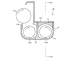
次に、画像形成装置100に備えられている現像装置2について詳細に説明する。図3は現像装置2の断面図であり、図4は、図3に示す現像装置2のA−A'線矢指図、図5は、図3に示す現像装置2のB−B'線矢指図である。
(Configuration of developing device)
Next, the developing
図3に示すように、現像装置2は、上記現像槽111内に、感光体ドラム3(図2参照)と対向するように配置された現像剤担持部材(現像ローラ)114を有し、現像剤担持部材114によって感光体ドラム3の表面にトナーを供給して、感光体ドラム3の表面に形成された静電潜像を顕像化する(現像する)装置である。
As shown in FIG. 3, the developing
図3に示すように、現像装置2は、現像槽111、現像剤担持部材114の他、現像槽カバー(天井面)115、ドクターブレード116、第1搬送スクリュー(第1搬送部材)112a、第2搬送スクリュー(第2搬送部材)112b、仕切り板(仕切り壁)113を備えている。
As shown in FIG. 3, the developing
現像槽111は、トナーとキャリアとを含む現像剤を収容する槽であり、該現像槽111に、現像剤担持部材114、第1搬送スクリュー112a、第2搬送スクリュー112bが配設されている。なお、本実施形態のキャリアは、磁性を有する磁性キャリアである。
The developing
現像剤担持部材114は、回転するマグネットローラであり、現像槽111の現像剤を表面に汲み上げて担持し、表面に担持している現像剤に含まれるトナーを感光体ドラム3に供給するものである。現像剤担持部材114の表面に近接する位置にはドクターブレード(層厚規制用ブレード)116が配されている。
The
また、図3に示すように、現像槽111の上側(H方向側)には、取り外し可能な現像槽カバー115が設けられている。この現像槽カバー115には、図4、図5に示すように、現像槽111に未使用のトナーを補給するためのトナー補給口117が形成されている。前述の図2に示したトナーホッパー101に収容されたトナーは、トナー移送機構102およびこのトナー補給口117を介して、現像槽111へと供給される。
Further, as shown in FIG. 3, a removable developing
第1搬送スクリュー112aおよび第2搬送スクリュー112bは、図4に示すように、現像槽111において現像剤を撹拌及び搬送するためのスクリュー形状のローラ(撹拌ローラ)である。第1搬送スクリュー112aおよび第2搬送スクリュー112bは、回転軸50の周囲に、現像剤を撹拌及び搬送するための螺旋状の搬送羽根51が形成されている。
As shown in FIG. 4, the
第1搬送スクリュー112aおよび第2搬送スクリュー112bは、互いの周面同士が、仕切り板113を介して対向するように、且つ互いの回転軸50同士が平行になるように並列されている。そして、第1搬送スクリュー112aおよび第2搬送スクリュー112bは、モータ等の駆動手段(図示せず)によって回転駆動されることで、互いに逆方向に現像剤を搬送するようになっている。本実施形態では、第1搬送スクリュー112aは、図4に示されるX方向に現像剤を搬送し、第2搬送スクリュー112bは、X方向とは逆のY方向に現像剤を搬送する。
The first conveying
上記仕切り板113は、第1搬送スクリュー112aと第2搬送スクリュー112bとの間に、第1および第2搬送スクリュー112a、112bの各回転軸50に平行に延設されている。この仕切り板113により、現像槽111の内部は、第1搬送スクリュー112aが配されている第1搬送路Pと、第2搬送スクリュー112bが配されている第2搬送路Qとに区画される。
The
また、仕切り板113は、第1搬送スクリュー112aおよび第2搬送スクリュー112bの各軸方向の両端部において、現像槽111の内側の壁面から離間して配置されている。これにより、現像槽111における、第1搬送スクリュー112aおよび第2搬送スクリュー112bの各回転軸方向の両端部付近には、第1搬送路Pと第2搬送路Qとを連通する連通路が形成されている。
Further, the
図4では、X方向下流側に形成されている連通路を第1連通路e、Y方向下流側に形成されている連通路を、第2連通路fとしている。 In FIG. 4, the communication path formed on the downstream side in the X direction is a first communication path e, and the communication path formed on the downstream side in the Y direction is a second communication path f.
このように区画された現像槽111内を、現像剤が循環搬送される。具体的には、第1搬送路Pにおいて、現像剤は、第1搬送スクリュー112aによって撹拌されながらX方向へ搬送され、第1連通路eに到達する。第1連通路eに到達した現像剤は、第1連通路eを通過して第2搬送路Qへと搬送され、第2搬送路Qを、第2搬送スクリュー112bによって、撹拌されながらY方向へ搬送され、第2連通路fに到達する。そして、第2連通路fに到達した現像剤は、第2連通路fを通過して再び第1搬送路Pへ搬送される。
The developer is circulated and conveyed in the developing
このようにして、現像剤は、現像槽111において、第1搬送路P、第1連通路e、第2搬送路Q、第2連通路fを、この順序にて循環搬送される。
In this way, the developer is circulated and conveyed in this order through the first conveyance path P, the first communication path e, the second conveyance path Q, and the second communication path f in the developing
そして、上記現像剤担持部材114は、第2搬送路Qに配置された第2搬送スクリュー112bの上方に位置しており、第2搬送路Qを搬送される現像剤の一部は、現像剤担持部材114の回転にてその表面に担持されて汲み上げられる。汲み上げられた現像剤中のトナーのみ感光体ドラム3へと移動し、汲み上げられた現像剤中のキャリアは、現像槽111内へと戻される。したがって、現像槽111内の現像剤は、トナーのみが順次消費されていく。
The
このようなトナーの消費を補うべく、前述したように、トナー補給口117より未使用の新しいトナーが補給される。本実施形態では、トナー補給口117は、図4に示すように、第1搬送路P内の領域であり、且つ第2連通路f近傍のX方向下流側の位置に形成されている。つまり、トナーは、第1搬送路Pにおける、現像剤の搬送方向上流位置に補給されるようになっている。
In order to compensate for such toner consumption, new unused toner is supplied from the
補給されたトナーは、第1搬送路Pを搬送される間に、第1搬送スクリュー112aによって撹拌され、従前より存在する現像剤と混合され帯電されることとなる。このような撹拌及びそれによる帯電は、補給されたトナーが、第1搬送路Pを搬送されている間に充分に行われ、現像剤担持部材114の汲み上げが行われる第2搬送路Qに到達したときには、充分な帯電量を帯びていることが好ましい。
The replenished toner is agitated by the first conveying
そして、このような補給されたトナーの撹拌及びそれによる帯電は、たとえ多量のトナーが補給されてしまい、従来の現像装置では、補給されたトナーが固まりとなって従前よりある現像剤の上面に載って搬送されてしまうような場合であっても、この固まりを効果的に分散させて、従前よりある現像剤と混合して撹拌することが必要である。 Such agitation of the replenished toner and charging due thereto causes a large amount of toner to be replenished, and in the conventional developing device, the replenished toner becomes hard and becomes on the upper surface of the existing developer. Even in the case of being carried on the board, it is necessary to effectively disperse this lump and to mix and agitate with a certain developer.
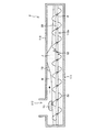
このようなことを可能とするために、本実施形態の現像装置2においては、図4、図5に示すように、X方向に搬送される現像剤を逆向きに搬送する戻し羽根52が設けられている。戻し羽根52は、トナー補給口117よりも現像剤の搬送方向(X方向)の下流側に配されており、搬送羽根51の間に配されている。
In order to make this possible, in the developing
戻し羽根52は、現像剤を循環方向とは逆向き(逆方向)に搬送する螺旋状のスクリューオーガよりなる構成である。そして、図6に示すように、現像剤を循環方向に搬送する螺旋状の搬送羽根51と戻し羽根52とは連続した状態、すなわち、搬送羽根51の端部51aと戻し羽根52の端部52aとが接触した状態で設けられる。
The
さらに、戻し羽根52の直径が、第1搬送スクリュー112aの搬送羽根51の直径よりも小さく設計されている。
Further, the diameter of the
(補給トナーと現像剤の混合)
図1に、本実施形態の現像装置2において、補給されたトナーが、従前よりある現像剤と混合される様子を示す。
(Mixing of supply toner and developer)
FIG. 1 shows how the replenished toner is mixed with a certain developer in the developing
現像槽111のトナー補給口117から補給された補給トナーT1は、第1搬送路Pを循環移動する現像剤(図1においてドットにて示されている領域)の上に落下するが、トナーの比重は、トナーとキャリアを含む現像剤の比重よりも極めて低い。例えば、トナーの比重は約0.35g/ccであるのに対し、現像剤の比重は約2g/cc程度である。そのため、現像剤上に補給された補給トナーの量が多い時、補給トナーT1は固まりのまま、現像剤と混ざることなく、当該現像剤の上面を滑りながら搬送される。
The replenishing toner T1 replenished from the
本実施形態においては、第1搬送スクリュー112aに、循環方向に搬送される現像剤を逆向きに搬送する戻し羽根52が、トナー補給口117よりも現像剤搬送方向の下流側に備えられている。
In the present embodiment, the first conveying
したがって、図1に示すように、この戻し羽根52の現像剤を逆方向に送る力にて、戻し羽根52の付近には、現像剤溜まりJが形成される。この現像剤溜まりJが形成されることで、現像剤の上面(液面)が膨れ上がり、現像剤の上面を滑りながら搬送されるトナーの固まりT1がそのまま通過していくことが阻止され、補給トナーの固まりT2は、強制的にほぐされる。
Therefore, as shown in FIG. 1, a developer pool J is formed in the vicinity of the
また、戻し羽根52の逆向きの回転により、現像剤の混合効果が高まり、補給されたトナーはここで従前よりある現像剤と十分に混合され、含まれるキャリアと摩擦されることで、必要な帯電量を得ることができる。
Further, the reverse rotation of the
これにより、補給トナーが固まりとなって現像剤の上を搬送されてきた場合であっても、充分に帯電されていないトナーが現像剤担持部材114に供給されることを効果的に抑制することができる。
Accordingly, even when the replenished toner is hardened and conveyed on the developer, it is possible to effectively suppress the supply of the toner that is not sufficiently charged to the
また、ここで、より好ましくは、図1に示すように、戻し羽根52による現像剤の逆向きの搬送により、戻し羽根52近傍の現像剤の上面が、第1搬送路Pの現像槽カバー115に接触するよう設計しておくことである。
More preferably, as shown in FIG. 1, the developer upper surface in the vicinity of the
第1搬送スクリュー112aに設けられる戻し羽根52付近に形成される現像剤溜まりJの上面が現像槽カバー115天井面と接触することで、補給トナーの固まりは、より確実により効果的にほぐされる。
The upper surface of the developer reservoir J formed in the vicinity of the
換言すれば、戻し羽根52による現像剤の逆向きの搬送により、戻し羽根52近傍の現像剤の上面が、第1搬送路Pの現像槽カバー115に接触するよう設計しておくことで、本願発明における、第1搬送路P内におけるトナー補給口117の循環方向下流側に、第1搬送路Pを搬送される現像剤の上部の空間W(図1参照)を封鎖する空間封鎖手段が構成される。
In other words, by designing the developer so that the upper surface of the developer in the vicinity of the
つまり、第1搬送スクリュー112aが、循環方向に搬送される現像剤を逆方向に搬送して現像剤溜まりJを形成する戻し羽根52を、トナー補給口117における循環方向下流側に備え、第1搬送スクリュー112aに備えられた戻し羽根52が上部空間封鎖手段として機能し、戻し羽根52にて形成される現像剤溜まりJを現像槽カバー115に接触させて、上部の空間Wを封鎖する。
In other words, the first conveying
上記構成によれば、戻し羽根52により、トナー補給口117の循環方向下流側において、第1搬送路Pを搬送される現像剤の上部の空間Wが封鎖されるので、この封鎖部にて、トナー補給口117より補給されたトナーが、固まった状態で、第1搬送路P内に従前からある現像剤の上面(現像剤面)を搬送され、移動していくことが阻止される。
According to the above configuration, the
これにより、補給トナーが固まりとなって現像剤の上を搬送されてきたとしても、補給されたトナーが従前からある現像剤と充分に混合されずに、充分に帯電されていない状態で現像剤担持部材114に供給されることを効果的に抑制することができ、画像形成装置100に搭載した場合に、カブリやトナー飛散の発生を抑えることができる。
As a result, even if the replenished toner is hardened and transported on the developer, the replenished toner is not sufficiently mixed with the developer, and the developer is not sufficiently charged. Supply to the
また、本実施形態では、上記戻し羽根52として、図1、図4〜図6に示すように、現像剤を循環方向とは逆向きに搬送する螺旋状のスクリューオーガよりなる構成としている。したがって、現像剤に対するストレス(せん断力)を著しく高めることなく、戻し羽52根付近に現像剤溜まりを形成することができるので、戻し羽根を、例えば、複数の攪拌羽根からなる攪拌部材により構成した場合と比べて、現像剤の磨耗劣化を抑えることができる。
In the present embodiment, as the
さらに、本実施形態では、第1搬送スクリュー112aが、戻し羽根52と連続して形成され、現像剤を循環方向に搬送する螺旋状の搬送羽根51を備える構成としているので、現像剤に対するストレス(せん断力)を高めることなく、現像剤を搬送することができ、充分に帯電されていないトナーが現像剤担持部材に供給されることを防止しながら現像剤の搬送速度を速くすることができる。
Furthermore, in the present embodiment, the first conveying
加えて、戻し羽根52の直径を、第1搬送スクリュー112aの搬送羽根51の直径よりも小さい構成としている。戻し羽根と搬送羽根の直径が同程度に形成されている構成では、現像剤を循環方向に搬送する力と現像剤を逆方向に搬送する力とが等しくなるため、現像剤に対して高いストレスがかかる。
In addition, the diameter of the
これに対し、上記構成のように、戻し羽根52を小さくしておくことで、現像剤に対し、循環方向に搬送する力と現像剤を逆方向に搬送する力とが加わったとしても、かかるストレスを直径が同様である構成よりも低くでき、著しく高いストレスを現像剤にかけることなく、補給トナーを従前よりある現像剤と混合させることができる。
On the other hand, if the
〔実施の形態2〕
本発明のその他の実施形態について、図7〜図9に基づいて説明すると以下の通りである。なお、説明の便宜上、実施の形態1で用いた部材と同じ機能を有する部材には同じ符号を付して説明を省略する。
[Embodiment 2]
Other embodiments of the present invention will be described below with reference to FIGS. For convenience of explanation, members having the same functions as those used in the first embodiment are denoted by the same reference numerals and description thereof is omitted.
本実施形態の現像装置が搭載される画像形成装置の構成や、現像装置の基本的な構成については、実施の形態1のものと同じであるので、ここでは、実施の形態1の現像装置2と、本実施形態の現像装置30との相違点のみ説明する。
Since the configuration of the image forming apparatus on which the developing device of the present embodiment is mounted and the basic configuration of the developing device are the same as those of the first embodiment, the developing
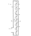
図7は現像装置30の断面図であり、図8は、図7に示す現像装置2のC−C'線矢指図である。実施の形態1の現像装置2との違いは、第1搬送路P内であって、図8に示すように、第1搬送スクリュー112aの戻し羽根52の上部位置に、現像剤の上面を規制する現像剤規制部材31が備えられている点である。現像剤規制部材31は、下部形状がアーチ型をした板状の部材であり、現像槽カバー(天井面)115の下面に設けられている。現像剤の上面を搬送される補給トナーをトラップするとともに、補給トナーと現像剤との混合を促進させるものである。
7 is a cross-sectional view of the developing
図9に、本実施形態の現像装置30において、補給されたトナーが、従前よりある現像剤と混合される様子を示す。
FIG. 9 shows how the replenished toner is mixed with a certain developer in the developing
図9に示すように、このような構成では、第1搬送スクリュー112aには、循環方向に搬送される現像剤に対して、逆向きに搬送する戻し羽根52が設けられると共に、戻し羽根52の上部に、現像剤規制部材31が配設されている。
As shown in FIG. 9, in such a configuration, the first conveying
これにより、戻し羽根52付近に現像剤溜まりJが形成され、この現像剤溜まりJにより、現像剤の上面が膨れ上がり、現像剤の上面を滑りながら搬送される補給トナーの固まりT3、T4がそのまま通り抜けることが阻止され、同時に補給トナーT3,T4が強制的に解される。また、戻し羽根52の逆向きの回転と現像剤規制部材31により、現像剤の混合効果が高まり、補給されたトナーはここで現像剤(キャリア)と十分に混合することによって、必要な帯電量を得ることができる。
As a result, a developer reservoir J is formed in the vicinity of the
また、ここで、上記現像剤規制部材31は、磁石より構成することがより好ましい。このような構成とすることで、従前よりある現像剤中のキャリアが、磁石よりなる現像剤規制部材31に引き付けられ、キャリア濃度の高い現像剤溜まりを形成できる。したがって、固まりとなって現像剤の上を搬送されてきた補給トナーは、このキャリア濃度の高い現像剤溜まりにおいて、ほぐされ、現像剤と混合されるので、より効果的に帯電させることが可能となる。
Here, the
また、換言すれば、第1搬送スクリュー112aが、循環方向に搬送される現像剤を逆方向に搬送して現像剤溜まりJを形成する戻し羽根52を、トナー補給口117における循環方向下流側に備え、戻し羽根52の上部に、循環方向に対して垂直に設けられた現像剤規制部材31を備える構成としておくことで、これら現像剤規制部材31と戻し羽根52とにより、本願発明における、第1搬送路P内におけるトナー補給口117の循環方向下流側に、第1搬送路Pを搬送される現像剤の上部の空間Wを封鎖する空間封鎖手段が構成される。
In other words, the first conveying
つまり、戻し羽根52にて形成される現像剤溜まりJを現像剤規制部材31で堰き止めることで現像剤溜まりJを現像槽カバー115に接触させて、現像剤の上部の空間Wを封鎖する。
That is, the developer reservoir J formed by the
現像剤規制部材31による現像剤を堰き止める力を利用しているので、戻し羽根52の作用のみでは現像剤溜まりJを現像槽カバーに接触させることができない場合、例えば、現像剤の流動性が高いような場合でも、簡単に現像剤溜まりJを現像槽カバー115に接触させて、現像剤の上部の空間Wを封鎖することができる。
Since the force of blocking the developer by the
また、逆に言えば、現像剤規制部材31は、戻し羽根52にて形成された現像剤溜まりJを堰き止めればよいので、戻し羽根52が供えられていない状態で、現像剤の上面を規制して、現像剤の上部の空間Wを封鎖する構成に比して、現像剤規制部材の下端と現像剤の上面との間の距離を長く確保でき、現像剤規制部材31が循環方向に搬送される現像剤の流れを堰き止めることで現像剤に与えるストレスを、極力小さくできる。
In other words, the
〔実施の形態3〕
本発明のその他の実施形態について、図10〜図13に基づいて説明すると以下の通りである。なお、説明の便宜上、実施の形態1、2で用いた部材と同じ機能を有する部材には同じ符号を付して説明を省略する。
[Embodiment 3]
Other embodiments of the present invention will be described below with reference to FIGS. For convenience of explanation, members having the same functions as those used in the first and second embodiments are given the same reference numerals and explanation thereof is omitted.
本実施形態の現像装置が搭載される画像形成装置の構成や、現像装置の基本的な構成については、実施の形態1、2のものと同じであるので、ここでは、実施の形態1、2の現像装置2,30と、本実施形態の現像装置202との相違点のみ説明する。
Since the configuration of the image forming apparatus on which the developing device of the present embodiment is mounted and the basic configuration of the developing device are the same as those of the first and second embodiments, here, the first and second embodiments. Only differences between the developing
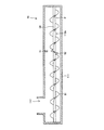
実施の形態2の現像装置30との違いは、図13に示すように、第1搬送スクリュー212aには、戻し羽根52が設けられておらず、この戻し羽根52の代わりに、図10、図11(a)及び図11(b)に示すように、第1搬送路P内の上部であって、かつ、第1搬送路P内におけるトナー補給口117の循環方向下流側に、第1搬送路Pを搬送される現像剤の上部の空間Wを封鎖する可動堰231(上部空間封鎖手段)が備えられている点である。
The difference from the developing
図10は現像装置202の断面図であり、図11(a)及び図11(b)は、図10に示す現像装置202のC−C'線矢指図である。より詳細には、図11(a)は、上部空間封鎖手段を構成する可動堰231が、現像剤を堰き止めた状態を示し、図11(b)は、可動堰231が、現像剤の堰き止めを解除している状態を示している。図11(a)及び図11(b)において、一点鎖線にて示すラインが、現像剤の上面である。また、図13は、図10に示す現像装置202のD−D'線矢指図である。
10 is a cross-sectional view of the developing
可動堰231は、図10に示すように、第1搬送スクリュー212aの現像剤搬送方向に対して垂直に設けられた現像剤規制部材231aと、現像剤規制部材231aを、現像剤の上面部分と接触する側とは反対側において回転自在に支持する回転軸231bと、該回転軸231bに回転駆動力を伝えるギア231cとを備えている。可動堰231は、現像剤規制部材231aを回転させて、現像剤の上部の空間Wの封鎖と開放とを行う。
As shown in FIG. 10, the
現像剤規制部材231aは、下部形状がアーチ型をした板状の部材であり、現像剤規制部材231aが、現像剤の上面と接触して現像剤を堰き止める状態で、現像槽カバー(天井面)115の下面に密着するよう設けられている。
The
可動堰231は、現像槽カバー115と現像剤との間に形成される現像剤の上部の空間Wを封鎖することにより、現像剤上面を搬送される補給トナーをトラップし、補給トナーと現像剤との混合を促進させるものである。
The
より詳細に言うと、可動堰231は、現像剤の上面を搬送されてきた補給トナーの固まりを、現像剤と現像槽カバーの間に挟んで解砕することで、確実に解すものである。
More specifically, the
図12(a)に、上部空間封鎖手段を構成する可動堰231にて現像剤の上面が堰き止められ、上部の空間Wを封鎖されている時の現像剤の様子を示す。可動堰231による封鎖は、トナー補給モード時に実施される。トナー補給モードとは、図示しないトナー濃度センサが、現像槽111内のトナー濃度が所定の範囲の下限を超えたと判断した場合に、トナーホッパー101よりトナー移送機構102を介して、現像槽111内にトナーを補給するモードである。トナーの補給は、トナー濃度センサにて、現像槽111内のトナー濃度が、予め定められているトナー補給を終了する基準値に到達したことが検出されるまで間欠的或いは連続的に継続され、上記基準値に到達したことが検出されることで、トナー補給モードが終了する。
FIG. 12A shows the state of the developer when the upper surface of the developer is blocked by the
一方、図12(b)に、可動堰231が、現像剤の堰き止めを解除し、上部の空間Wを解放している時の現像剤の様子を示す。可動堰231は、トナー補給モード時以外は、せき止めを解除している。なお、図12(a)及び図12(b)は共に、図10に示す現像装置202のC−C'線矢指図である。
On the other hand, FIG. 12B shows the state of the developer when the
図12(a)に示すように、トナー補給時に現像剤の上部の空間Wを封鎖されるので、現像剤規制部材231aの手前で現像剤溜まりJが形成され、この現像剤溜まりJにより、現像剤の上面を滑りながら搬送される補給トナーの固まりT3、T4がそのまま通り抜けることが阻止され、同時に補給トナーT3,T4が強制的に解される。補給されたトナーは、ここで現像剤(キャリア)と十分に混合することによって、必要な帯電量を得ることができる。
As shown in FIG. 12A, since the space W above the developer is sealed when the toner is replenished, a developer reservoir J is formed in front of the
そして、図12(b)に示すように、トナー補給時以外には、上部の空間Wが開放されるので、現像剤にストレスを与えることなく、現像剤を搬送することができる。 Then, as shown in FIG. 12B, since the upper space W is opened except when the toner is replenished, the developer can be conveyed without applying stress to the developer.
また、トナー補給モードであるかどうかで、可動堰231における封鎖と解放を切り替える構成は、例えば、前記したトナー濃度センサの検出結果に基づいて、可動堰231の回転を制御することで、容易に実現できる。
Further, the configuration for switching between blocking and releasing in the
可動堰231にて堰き止めを解除するタイミングは、トナー濃度センサにて、トナー補給を終了する基準値に到達したことが検出されたと同時とするのではなく、最後に補給されたトナーが、現像剤溜まりJにて十分に解されるのに必要な時間だけ遅延させることが好ましい。これにより、最後に補給されたトナーについても、現像剤溜まりJにて十分に解すことができる。
The timing of releasing the dam by the
さらに、可動堰231においては、図12(b)に示すように、現像剤規制部材231aが、上部の空間Wを解放するにあたり、現像剤の循環方向下流側に回転する構成であることが好ましい。
Furthermore, as shown in FIG. 12B, the
これは、もし、現像剤規制部材231aが、上部の空間Wを解放するにあたり、現像剤の循環方向上流側に回転する構成の場合、現像剤規制部材231aと現像槽カバー115との間に現像剤を挟み込んで、堰き止めを解除できない虞があるためである。上記構成とすることで、現像剤規制部材231aと現像槽カバー115との間に現像剤を挟み込んだりすることなく、可動堰231を開放することができる。
This is because if the
〔実施の形態4〕
本発明のその他の実施形態について、図14に基づいて説明すると以下の通りである。なお、説明の便宜上、実施の形態1〜3で用いた部材と同じ機能を有する部材には同じ符号を付して説明を省略する。
[Embodiment 4]
Another embodiment of the present invention is described below with reference to FIG. For convenience of explanation, members having the same functions as those used in the first to third embodiments are given the same reference numerals and explanation thereof is omitted.
本実施形態の現像装置が搭載される画像形成装置の構成や、現像装置の基本的な構成については、実施の形態1〜3のものと同じであるので、ここでは、実施の形態1〜3の現像装置2,30、202と、本実施形態の現像装置232との相違点のみ説明する。
Since the configuration of the image forming apparatus on which the developing device of the present embodiment is mounted and the basic configuration of the developing device are the same as those of the first to third embodiments, here, the first to third embodiments. Only the differences between the developing
実施の形態3の現像装置202との違いは、図14に示すように、第1搬送路Pに、第1搬送スクリュー212aに換えて、実施の形態1の現像装置2と同じ、トナー補給口117の循環方向下流側に戻し羽根52を備えた第1搬送スクリュー112aが配置されている点である。可動堰231は、上記戻し羽根52の上部に位置する。
The difference from the developing
つまり、本実施形態の現像装置202は、実施の形態30の現像装置における現像剤規制部材31を可動堰231に置き換えた構成であるともいえる。
That is, it can be said that the developing
これにより、トナー補給モード時以外は、現像剤の搬送を堰き止めることなく、最もストレスのかからない構成でありながら、トナー補給モード時は、補給されたトナーを、戻し羽根52による作用とで、最も効果的に従前よりある現像剤と混合させ、効果的に摩擦帯電させることが可能となる。
Thus, except for the toner replenishment mode, the developer transport is not disturbed and is the least stressed. However, in the toner replenishment mode, the replenished toner is most affected by the action of the
本発明は上述した各実施形態に限定されるものではなく、請求項に示した範囲で種々の変更が可能であり、上述した実施形態において開示された各技術的手段を適宜組み合わせて得られる実施形態についても本発明の技術的範囲に含まれる。 The present invention is not limited to the above-described embodiments, and various modifications are possible within the scope shown in the claims, and the embodiments can be obtained by appropriately combining the respective technical means disclosed in the above-described embodiments. The form is also included in the technical scope of the present invention.
本発明の現像装置および画像形成装置は、電子写真方式の複合機,複写機,プリンタ,ファクシミリに好適である。 The developing device and the image forming apparatus of the present invention are suitable for electrophotographic multifunction devices, copying machines, printers, and facsimiles.
2 現像装置
30 現像装置
31 現像剤規制部材
52 戻し羽根
100 画像形成装置
111 現像槽
112a 第1搬送スクリュー(第1搬送部材)
112b 第2搬送スクリュー(第2搬送部材)
113 仕切り部材
114 現像剤担持部材
115 現像槽カバー(天井面)
117 トナー補給口(補給口)
202 現像装置
231 可動堰
231a 現像剤規制部材
231b 回転軸
231c ギア
232 現像装置
P 第1搬送路
Q 第2搬送路
T1〜T4 補給トナー
e 第1連通路
f 第2連通路
2 Developing
112b Second conveying screw (second conveying member)
113
117 Toner supply port (supply port)
202
Claims (12)
前記第1搬送路内における前記トナー補給口の循環方向下流側に、当該第1搬送路を搬送される現像剤の上部の空間を封鎖する上部空間封鎖手段が設けられていることを特徴とする現像装置。 A developer tank containing a developer including toner and a carrier; first and second transport paths provided in the developer tank for transporting the developer; and provided in the first transport path. A first transport member that transports the developer in a predetermined direction while stirring the developer in the first transport path, and the predetermined direction while stirring the developer in the second transport path provided in the second transport path. A second conveying member that conveys in the opposite direction, first and second communicating paths that communicate the ends of the first and second conveying paths on both sides in the longitudinal direction, and the developer in the second conveying path. A developer carrying member that carries the toner contained in the developer to the photoreceptor, and a developer tank cover that covers the upper surface of the developer conveyed in the first conveyance path, leaving a space in the upper part; A toner replenishing port for replenishing toner to the first transport path, Image agent, wherein the first conveyance path, the first communication path, a second conveying path, and a second communication path in the developing device is transported to circulate in this order,
An upper space blocking means for blocking an upper space of the developer conveyed through the first conveyance path is provided on the downstream side in the circulation direction of the toner supply port in the first conveyance path. Development device.
前記上部空間封鎖手段が、前記第1搬送部材に備えられた前記戻し羽根よりなり、該戻し羽根にて形成される前記現像剤溜まりを前記現像槽カバーに接触させて、前記上部の空間を封鎖することを特徴とする請求項1に記載の現像装置。 The first transport member includes a return blade that transports the developer transported in the circulation direction in the reverse direction to form a developer reservoir on the downstream side in the circulation direction of the toner supply port.
The upper space sealing means includes the return blade provided in the first conveying member, and the developer reservoir formed by the return blade is brought into contact with the developer tank cover to seal the upper space. The developing device according to claim 1, wherein:
前記現像剤規制部材が磁石よりなることを特徴とする請求項6に記載の現像装置。 The carrier is a magnetic carrier;
The developing device according to claim 6, wherein the developer regulating member is made of a magnet.
該可動堰は、トナー補給モード時に前記上部の空間を封鎖し、トナー補給モード時以外には、前記上部の空間を開放することを特徴とする請求項1に記載の現像装置。 The upper space blocking means contacts the upper surface portion of the developer transported in the first transport path provided downstream in the circulation direction of the toner supply port in the first transport path. It consists of a movable weir that dams the agent,
The developing device according to claim 1, wherein the movable weir blocks the upper space during the toner replenishment mode and opens the upper space except during the toner replenishment mode.
前記戻し羽根の上部には、前記循環方向に対して垂直に設けられた現像剤規制部材を備え、
前記上部空間封鎖手段が、前記現像剤規制部材と前記第1搬送部材に備えられた前記戻し羽根よりなり、該戻し羽根にて形成される前記現像剤溜まりを前記現像剤規制部材で堰き止めることで該現像剤溜まりを前記現像槽カバーに接触させて、前記上部の空間を封鎖することを特徴とする請求項1に記載の現像装置。 The first transport member includes a return blade that transports the developer transported in the circulation direction in the reverse direction to form a developer reservoir on the downstream side in the circulation direction of the toner supply port.
On the upper part of the return blade, a developer regulating member provided perpendicular to the circulation direction is provided,
The upper space blocking means includes the developer regulating member and the return blade provided in the first transport member, and blocks the developer pool formed by the return blade with the developer regulating member. The developing device according to claim 1, wherein the developer reservoir is brought into contact with the developer tank cover to seal the upper space.
Priority Applications (1)
| Application Number | Priority Date | Filing Date | Title |
|---|---|---|---|
| JP2008334746A JP5248307B2 (en) | 2008-06-16 | 2008-12-26 | Developing device and image forming apparatus having the same |
Applications Claiming Priority (3)
| Application Number | Priority Date | Filing Date | Title |
|---|---|---|---|
| JP2008156444 | 2008-06-16 | ||
| JP2008156444 | 2008-06-16 | ||
| JP2008334746A JP5248307B2 (en) | 2008-06-16 | 2008-12-26 | Developing device and image forming apparatus having the same |
Publications (2)
| Publication Number | Publication Date |
|---|---|
| JP2010026487A true JP2010026487A (en) | 2010-02-04 |
| JP5248307B2 JP5248307B2 (en) | 2013-07-31 |
Family
ID=41732336
Family Applications (1)
| Application Number | Title | Priority Date | Filing Date |
|---|---|---|---|
| JP2008334746A Active JP5248307B2 (en) | 2008-06-16 | 2008-12-26 | Developing device and image forming apparatus having the same |
Country Status (1)
| Country | Link |
|---|---|
| JP (1) | JP5248307B2 (en) |
Cited By (2)
| Publication number | Priority date | Publication date | Assignee | Title |
|---|---|---|---|---|
| JP2014044453A (en) * | 2013-12-12 | 2014-03-13 | Kyocera Document Solutions Inc | Developing device, and image forming apparatus including the same |
| CN104076652A (en) * | 2013-03-26 | 2014-10-01 | 富士施乐株式会社 | Powder transport device, developing device, and image forming apparatus |
Citations (17)
| Publication number | Priority date | Publication date | Assignee | Title |
|---|---|---|---|---|
| JPH05238047A (en) * | 1991-11-20 | 1993-09-17 | Casio Comput Co Ltd | Electrostatic recorder |
| JPH0583776U (en) * | 1992-04-14 | 1993-11-12 | シャコー株式会社 | Developing device for electrophotographic copying machine |
| JPH0683184A (en) * | 1992-08-31 | 1994-03-25 | Mita Ind Co Ltd | Developing device |
| JPH09114243A (en) * | 1995-10-20 | 1997-05-02 | Fuji Xerox Co Ltd | Developing device |
| JPH11288158A (en) * | 1998-02-04 | 1999-10-19 | Minolta Co Ltd | Developing device |
| JP2000137383A (en) * | 1998-11-02 | 2000-05-16 | Sharp Corp | Developing device |
| JP2001166575A (en) * | 1999-12-09 | 2001-06-22 | Canon Inc | Developing device, processing cartridge and image forming device |
| JP2001183899A (en) * | 1999-12-24 | 2001-07-06 | Fuji Xerox Co Ltd | Developer carrying member and developing device using it |
| JP2003114576A (en) * | 2001-10-03 | 2003-04-18 | Canon Inc | Developing device, process cartridge, image forming device and electrophotographic image forming device |
| JP2005099144A (en) * | 2003-09-22 | 2005-04-14 | Canon Inc | Developing device |
| JP2005202242A (en) * | 2004-01-16 | 2005-07-28 | Ricoh Co Ltd | Developing device, processing cartridge and image forming apparatus |
| JP2005316161A (en) * | 2004-04-28 | 2005-11-10 | Fuji Xerox Co Ltd | Development apparatus, rotating type developing apparatus and image forming apparatus |
| JP2006058696A (en) * | 2004-08-20 | 2006-03-02 | Ricoh Co Ltd | Developing device, image forming unit, and image forming apparatus having them |
| JP2007025638A (en) * | 2005-06-13 | 2007-02-01 | Ricoh Co Ltd | Developing device, process cartridge, and image forming apparatus |
| JP2007148053A (en) * | 2005-11-29 | 2007-06-14 | Ricoh Co Ltd | Developing device, process cartridge and image forming apparatus |
| JP2008015199A (en) * | 2006-07-05 | 2008-01-24 | Mitsubishi Gas Chem Co Inc | Resin composition for optical material, and optical element |
| JP2008151997A (en) * | 2006-12-18 | 2008-07-03 | Fuji Xerox Co Ltd | Developer conveying device, developing device, visible image forming apparatus, and image forming apparatus |
-
2008
- 2008-12-26 JP JP2008334746A patent/JP5248307B2/en active Active
Patent Citations (17)
| Publication number | Priority date | Publication date | Assignee | Title |
|---|---|---|---|---|
| JPH05238047A (en) * | 1991-11-20 | 1993-09-17 | Casio Comput Co Ltd | Electrostatic recorder |
| JPH0583776U (en) * | 1992-04-14 | 1993-11-12 | シャコー株式会社 | Developing device for electrophotographic copying machine |
| JPH0683184A (en) * | 1992-08-31 | 1994-03-25 | Mita Ind Co Ltd | Developing device |
| JPH09114243A (en) * | 1995-10-20 | 1997-05-02 | Fuji Xerox Co Ltd | Developing device |
| JPH11288158A (en) * | 1998-02-04 | 1999-10-19 | Minolta Co Ltd | Developing device |
| JP2000137383A (en) * | 1998-11-02 | 2000-05-16 | Sharp Corp | Developing device |
| JP2001166575A (en) * | 1999-12-09 | 2001-06-22 | Canon Inc | Developing device, processing cartridge and image forming device |
| JP2001183899A (en) * | 1999-12-24 | 2001-07-06 | Fuji Xerox Co Ltd | Developer carrying member and developing device using it |
| JP2003114576A (en) * | 2001-10-03 | 2003-04-18 | Canon Inc | Developing device, process cartridge, image forming device and electrophotographic image forming device |
| JP2005099144A (en) * | 2003-09-22 | 2005-04-14 | Canon Inc | Developing device |
| JP2005202242A (en) * | 2004-01-16 | 2005-07-28 | Ricoh Co Ltd | Developing device, processing cartridge and image forming apparatus |
| JP2005316161A (en) * | 2004-04-28 | 2005-11-10 | Fuji Xerox Co Ltd | Development apparatus, rotating type developing apparatus and image forming apparatus |
| JP2006058696A (en) * | 2004-08-20 | 2006-03-02 | Ricoh Co Ltd | Developing device, image forming unit, and image forming apparatus having them |
| JP2007025638A (en) * | 2005-06-13 | 2007-02-01 | Ricoh Co Ltd | Developing device, process cartridge, and image forming apparatus |
| JP2007148053A (en) * | 2005-11-29 | 2007-06-14 | Ricoh Co Ltd | Developing device, process cartridge and image forming apparatus |
| JP2008015199A (en) * | 2006-07-05 | 2008-01-24 | Mitsubishi Gas Chem Co Inc | Resin composition for optical material, and optical element |
| JP2008151997A (en) * | 2006-12-18 | 2008-07-03 | Fuji Xerox Co Ltd | Developer conveying device, developing device, visible image forming apparatus, and image forming apparatus |
Cited By (5)
| Publication number | Priority date | Publication date | Assignee | Title |
|---|---|---|---|---|
| CN104076652A (en) * | 2013-03-26 | 2014-10-01 | 富士施乐株式会社 | Powder transport device, developing device, and image forming apparatus |
| JP2014191038A (en) * | 2013-03-26 | 2014-10-06 | Fuji Xerox Co Ltd | Powder conveyance device, developing device, and image forming apparatus |
| US9201346B2 (en) | 2013-03-26 | 2015-12-01 | Fuji Xerox Co., Ltd. | Powder transport device, developing device, and image forming apparatus |
| CN104076652B (en) * | 2013-03-26 | 2020-04-07 | 富士施乐株式会社 | Powder conveying device, developing device, and image forming apparatus |
| JP2014044453A (en) * | 2013-12-12 | 2014-03-13 | Kyocera Document Solutions Inc | Developing device, and image forming apparatus including the same |
Also Published As
| Publication number | Publication date |
|---|---|
| JP5248307B2 (en) | 2013-07-31 |
Similar Documents
| Publication | Publication Date | Title |
|---|---|---|
| JP4709295B2 (en) | Developing device and image forming apparatus using the same | |
| JP4846828B2 (en) | Developing device and image forming apparatus using the same | |
| JP2008151997A (en) | Developer conveying device, developing device, visible image forming apparatus, and image forming apparatus | |
| JP2010176075A (en) | Developing device and image forming apparatus | |
| JP2011081215A (en) | Toner cartridge and image forming apparatus including the same | |
| JP2011059239A (en) | Image forming apparatus | |
| JP4613239B2 (en) | Developing device and image forming apparatus using the same | |
| JP5005792B2 (en) | Developing device and image forming apparatus having the same | |
| JP5248307B2 (en) | Developing device and image forming apparatus having the same | |
| JP2008015262A (en) | Developing device | |
| JP2009168954A (en) | Development apparatus and image forming apparatus | |
| JP2010038939A (en) | Developing device and image forming apparatus using the same | |
| JP2010197839A (en) | Developing device and image forming apparatus using the same | |
| JP5284002B2 (en) | Developing device and image forming apparatus using the same | |
| JP5612294B2 (en) | Image forming apparatus | |
| JP2006323049A (en) | Developing unit and image forming device using it | |
| JP5193923B2 (en) | Developing device and image forming apparatus | |
| JP5165493B2 (en) | Developing device and image forming apparatus using the same | |
| JP2010066394A (en) | Developing device, image forming apparatus using the same, and method for controlling toner supply | |
| JP4444086B2 (en) | Toner transfer mechanism, developing unit, and image forming apparatus | |
| JP2010164691A (en) | Developing device and image forming apparatus using the same | |
| JP2010160253A (en) | Developing device and image forming device using the same | |
| JP4856690B2 (en) | Developing device and image forming apparatus | |
| JP2006235474A (en) | Developing device, process cartridge, and image forming apparatus | |
| JP4643336B2 (en) | Developing device, image forming apparatus, and process cartridge |
Legal Events
| Date | Code | Title | Description |
|---|---|---|---|
| A621 | Written request for application examination |
Free format text: JAPANESE INTERMEDIATE CODE: A621 Effective date: 20110223 |
|
| A977 | Report on retrieval |
Free format text: JAPANESE INTERMEDIATE CODE: A971007 Effective date: 20120725 |
|
| A131 | Notification of reasons for refusal |
Free format text: JAPANESE INTERMEDIATE CODE: A131 Effective date: 20120731 |
|
| A521 | Written amendment |
Free format text: JAPANESE INTERMEDIATE CODE: A523 Effective date: 20121001 |
|
| TRDD | Decision of grant or rejection written | ||
| A01 | Written decision to grant a patent or to grant a registration (utility model) |
Free format text: JAPANESE INTERMEDIATE CODE: A01 Effective date: 20130312 |
|
| A61 | First payment of annual fees (during grant procedure) |
Free format text: JAPANESE INTERMEDIATE CODE: A61 Effective date: 20130410 |
|
| R150 | Certificate of patent or registration of utility model |
Ref document number: 5248307 Country of ref document: JP Free format text: JAPANESE INTERMEDIATE CODE: R150 Free format text: JAPANESE INTERMEDIATE CODE: R150 |
|
| FPAY | Renewal fee payment (event date is renewal date of database) |
Free format text: PAYMENT UNTIL: 20160419 Year of fee payment: 3 |