JP2010025824A - Battery pack monitoring device - Google Patents
Battery pack monitoring device Download PDFInfo
- Publication number
- JP2010025824A JP2010025824A JP2008189090A JP2008189090A JP2010025824A JP 2010025824 A JP2010025824 A JP 2010025824A JP 2008189090 A JP2008189090 A JP 2008189090A JP 2008189090 A JP2008189090 A JP 2008189090A JP 2010025824 A JP2010025824 A JP 2010025824A
- Authority
- JP
- Japan
- Prior art keywords
- monitoring unit
- monitoring
- signal
- state
- upstream
- Prior art date
- Legal status (The legal status is an assumption and is not a legal conclusion. Google has not performed a legal analysis and makes no representation as to the accuracy of the status listed.)
- Granted
Links
Images


Classifications
-
- Y—GENERAL TAGGING OF NEW TECHNOLOGICAL DEVELOPMENTS; GENERAL TAGGING OF CROSS-SECTIONAL TECHNOLOGIES SPANNING OVER SEVERAL SECTIONS OF THE IPC; TECHNICAL SUBJECTS COVERED BY FORMER USPC CROSS-REFERENCE ART COLLECTIONS [XRACs] AND DIGESTS
- Y02—TECHNOLOGIES OR APPLICATIONS FOR MITIGATION OR ADAPTATION AGAINST CLIMATE CHANGE
- Y02E—REDUCTION OF GREENHOUSE GAS [GHG] EMISSIONS, RELATED TO ENERGY GENERATION, TRANSMISSION OR DISTRIBUTION
- Y02E60/00—Enabling technologies; Technologies with a potential or indirect contribution to GHG emissions mitigation
- Y02E60/10—Energy storage using batteries
Landscapes
- Measurement Of Current Or Voltage (AREA)
- Tests Of Electric Status Of Batteries (AREA)
- Charge And Discharge Circuits For Batteries Or The Like (AREA)
- Secondary Cells (AREA)
Abstract
Description
この発明は、複数のセルを直列に接続した組電池の充電状態を監視する組電池監視装置に関するものである。 The present invention relates to an assembled battery monitoring device that monitors the state of charge of an assembled battery in which a plurality of cells are connected in series.
近年注目を浴びているハイブリッド自動車において、エネルギー効率が高いリチウムイオン電池が注目を浴びている。このリチウムイオン電池は容量が大きいという利点を有する反面、過充電では、発熱・発火の危険があり、過放電では、電極が溶出して寿命が低下するといった欠点を有している。そのため、リチウムイオン電池に対して各ブロックの充電状態を監視する組電池監視装置を接続するのが一般的である。 In hybrid vehicles that have been attracting attention in recent years, lithium ion batteries with high energy efficiency have been attracting attention. While this lithium ion battery has the advantage of a large capacity, there is a risk that overcharge may cause heat generation and ignition, and overdischarge will result in electrode elution and a decrease in life. Therefore, it is common to connect an assembled battery monitoring device that monitors the charge state of each block to the lithium ion battery.
このような組電池監視装置に対して制御を行う制御装置は低圧で駆動するため、組電池監視装置と制御装置とは通常フォトカプラ等の絶縁素子を用いて信号の伝達が行われる。このような絶縁素子は高額なため、その使用個数は少ないことが望ましい。このような問題に解決するべく、例えば、特許文献1の図1に示すように、監視ユニットの入出力を直列に接続する、いわゆるラダー構成の組電池監視装置が提案されている。
Since a control device that controls such an assembled battery monitoring device is driven at a low pressure, signals are transmitted between the assembled battery monitoring device and the control device usually using an insulating element such as a photocoupler. Since such insulating elements are expensive, it is desirable that the number of them used be small. In order to solve such a problem, for example, as shown in FIG. 1 of
特許文献1に示す図1を用いて、ラダー構成の組電池監視装置について説明する。最も上流に位置する監視ユニットU1は、制御装置(マイコン)から電池状態の監視を指示する指示信号を受け取り、指示信号に基づいた監視の結果である状態信号を生成する。そして、その指示信号と状態信号を監視ユニットU1→監視ユニットU2→・・・→監視ユニットUnと次々に伝達してゆく。状態信号は各監視ユニットの監視結果に応じて、更新されてゆき、最も下流に位置する監視ユニットUnは下流に位置するフォトカプラを介して制御装置に状態信号を伝達する。ラダー構成の組電池監視装置は、両端の監視ユニットのみが低圧側の制御装置と直接情報のやり取りを行うため、フォトカプラを最上流のブロックと最下流のブロックに配置するだけですみ、フォトカプラの個数を減らすことができる利点がある。
しかしながら、ラダー構成の組電池監視装置は、電光変換により信号を伝達するものであるため、最も下流のブロックであるセルBn1〜Bnmと接続された下流のフォトカプラは、電光変換を行うたびにセルBn1〜Bnmの電力を消費する。このため、他のセルB11〜B(n−1)mと比べて、セルBn1〜Bnmの消費電力が多くなってしまう。この結果、充電状態のばらつきが広がり、組電池の充電状態の使用領域が狭まる問題があった。 However, since the assembled battery monitoring device of the ladder configuration transmits a signal by electro-optic conversion, the downstream photocoupler connected to the cells Bn1 to Bnm which are the most downstream blocks each time the electro-optic conversion is performed. It consumes Bn1-Bnm power. For this reason, the power consumption of the cells Bn1 to Bnm is increased compared to the other cells B11 to B (n-1) m. As a result, there has been a problem that the variation in the charged state is widened and the use area of the charged state of the assembled battery is narrowed.
本発明は上記課題に鑑みたものであり、ラダー形式の組電池監視装置における組電池の消費電流のばらつきを低減することを目的とする。 The present invention has been made in view of the above problems, and an object of the present invention is to reduce variations in current consumption of assembled batteries in a ladder-type assembled battery monitoring apparatus.
請求項1に係る発明は、単一セル又は複数セルの直列接続体からなるブロックを複数直列に接続することでなる組電池に対して、ブロック単位毎にセルの充電状態を監視する監視ユニットの直列接続体として構成される組電池監視装置において、最も上流に位置する最上流監視ユニットは、監視ユニットに対して電池状態の監視を指示する制御部からの指示信号を上流の絶縁素子を介して受け取り、最も下流に位置する最下流監視ユニットは、全ブロックの監視結果を示す最終監視結果信号を下流の絶縁素子を介して制御部へ送り、最上流監視ユニットと最下流監視ユニットとの間に位置する中継監視ユニットは、上流の監視ユニットから伝達された上流の監視ユニットの監視結果に中継監視ユニットの監視結果を反映させた状態信号を下流の監視ユニットに伝達するものであって、最上流監視ユニットと中継監視ユニットは、下流の絶縁素子の通電状態に応じて監視対象のブロックを放電する放電手段を有することを特徴とする。
The invention according to
上記構成では、下流の絶縁素子の通電状態に応じて、最上流監視ユニットの放電手段と中継監視ユニットの放電手段を放電するため、下流の絶縁素子に起因して最下流のブロックの充電状態のみが他のブロックの充電状態よりも低下して、充電状態がばらつく事態を軽減できる。 In the above configuration, since the discharging means of the most upstream monitoring unit and the discharging means of the relay monitoring unit are discharged according to the energization state of the downstream insulating element, only the charging state of the most downstream block is caused by the downstream insulating element. However, it is possible to reduce the situation where the charging state varies due to the lowering of the charging state of the other blocks.
請求項2に係る発明は、通電状態は、最終監視結果信号に基づいて判断することを特徴とする。
The invention according to
上記構成では、最終監視結果信号によって、下流の絶縁素子が通電しているか否かを把握する。この結果、下流の絶縁素子の通電経路に、電流センサなどを設けずとも下流の絶縁素子の通電状態を把握できる。 In the above configuration, whether or not the downstream insulating element is energized is determined based on the final monitoring result signal. As a result, the energization state of the downstream insulation element can be grasped without providing a current sensor or the like in the energization path of the downstream insulation element.
請求項3に係る発明は、中継監視ユニットと最下流監視ユニットは、最終監視結果信号を上流の監視ユニットに伝達する最終監視結果伝達手段を有し、最上流監視ユニットと中継監視ユニットは最終監視結果信号に基づいて放電手段を放電することを特徴とする。 According to a third aspect of the present invention, the relay monitoring unit and the most downstream monitoring unit have final monitoring result transmission means for transmitting a final monitoring result signal to an upstream monitoring unit, and the most upstream monitoring unit and the relay monitoring unit perform final monitoring. The discharging means is discharged based on the result signal.
上記構成では、最終監視結果伝達手段を介して、最上流監視ユニットと中継監視ユニットは最下流の監視ユニットが下流の絶縁素子に対して電池状態が伝達されているかを把握することができる。この結果、下流の監視ユニットにおいて、下流の絶縁素子を通電させる状態信号が生成された場合にも上流の監視ユニットは、その旨を把握することができる。 In the above configuration, the most upstream monitoring unit and the relay monitoring unit can grasp whether the battery state is transmitted to the downstream insulating element via the final monitoring result transmission unit. As a result, even when the downstream monitoring unit generates a state signal for energizing the downstream insulating element, the upstream monitoring unit can recognize that fact.
請求項4に係る発明は、監視ユニットは、最終監視結果信号と状態信号に応じて放電状態になることを特徴とする。 The invention according to claim 4 is characterized in that the monitoring unit enters a discharge state in accordance with the final monitoring result signal and the status signal.
上記構成では、状態信号の差異により、各監視ユニットの消費電力に差がでるような場合において、消費電力の小さい監視ユニットの放電回路を放電することで、状態信号の差異に基づく消費電力のばらつきを軽減することができる。 In the above configuration, in the case where there is a difference in power consumption of each monitoring unit due to a difference in status signal, the power consumption varies based on the difference in status signal by discharging the discharge circuit of the monitoring unit with low power consumption. Can be reduced.
請求項5に係る発明は、状態信号は電圧又は電流の大きさに基づくレベルによって信号の状態を表すものであって、監視ユニットからの出力信号として出力される状態信号のレベルと、監視ユニットへ入力信号として入力される状態信号のレベルが異なる特定の監視ユニットを検知し、出力信号のレベルが入力信号のレベルよりも大きい場合に、特定の監視ユニットよりも上流に位置する監視ユニットの放電手段を放電し、出力信号のレベルが入力信号のレベルよりも小さい場合に、特定の監視ユニットの放電手段と監視ユニットよりも下流に位置する放電手段とを放電することを特徴とする。 In the invention according to claim 5, the status signal represents the status of the signal by a level based on the magnitude of the voltage or current, and the level of the status signal output as the output signal from the monitoring unit and to the monitoring unit Discharging means for a monitoring unit located upstream from a specific monitoring unit when a specific monitoring unit having a different level of the state signal input as an input signal is detected and the level of the output signal is greater than the level of the input signal When the level of the output signal is smaller than the level of the input signal, the discharging means of the specific monitoring unit and the discharging means positioned downstream of the monitoring unit are discharged.
上記構成では、入力信号のレベルと出力信号のレベルが異なる特定の監視ユニットを検知し、その監視ユニットを基点として前後の監視ユニットの放電する。この結果、状態信号による通電状態の差異に起因する各ブロック間の充電状態のばらつきを低減できる。 In the above configuration, a specific monitoring unit having a different input signal level and output signal level is detected, and the preceding and following monitoring units are discharged with the monitoring unit as a base point. As a result, it is possible to reduce the variation in the charging state between the blocks due to the difference in the energized state due to the state signal.
請求項6に係る発明は、指示信号は全放電指令を示す情報をも更に含んでおり、全放電指令を示す指示信号を受信した監視ユニットは放電手段を放電状態にすることを特徴とする。 The invention according to claim 6 is characterized in that the instruction signal further includes information indicating the total discharge command, and the monitoring unit that has received the instruction signal indicating the total discharge command sets the discharge means to the discharge state.
過充電防止機能に異常が生じ、充電を停止すべき状況においても充電をし続けるような場合において、すべての放電手段を強制的に放電状態にして異常充電による悪影響を軽減するフェールセーフの役割を果たすことができる。 In the case where an abnormality occurs in the overcharge prevention function and charging continues even in a situation where charging should be stopped, the role of fail-safe to alleviate the adverse effects of abnormal charging by forcibly discharging all the discharge means Can fulfill.
請求項7に係る発明は、指示信号は、監視ユニットとブロックの診断指示を示す情報を更に含んでおり、監視ユニットは、診断支持に応じて放電手段を放電して監視対象のブロックの充電状態の変化量を測定し、変化量に基づいて監視ユニット又は監視対象のブロックに異常があるか否かを判定することを特徴とする。 In the invention according to claim 7, the instruction signal further includes information indicating a diagnosis instruction of the monitoring unit and the block, and the monitoring unit discharges the discharging means in response to the diagnosis support to charge the monitoring target block. And measuring whether or not there is an abnormality in the monitoring unit or the block to be monitored based on the amount of change.
診断指示を示す指示信号を受け取った監視ユニットは、放電手段を放電して、監視対象ブロックの状電状態の変化量を測定するため、その測定結果に基づいて、放電手段が正確に動作しているか、などの監視ユニット内の異常を診断するチェッキング機能を果たすことができる。 The monitoring unit that has received the instruction signal indicating the diagnosis instruction discharges the discharging means and measures the amount of change in the state of the electric current of the monitored block, so that the discharging means operates accurately based on the measurement result. A checking function for diagnosing an abnormality in the monitoring unit such as whether or not can be achieved.
(実施例1)
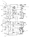
図1に本発明の実施例1に係る組電池の充電状態を監視する組電池監視装置1、図2に監視ユニットのブロック回路図を示す。
Example 1
FIG. 1 shows an assembled
組電池10は、単一個のセル又は複数セルの直列接続体からなるブロックBLを、さらに複数直列に接続することで構成される。一番上のブロックでは、セルB11からセルB1mまでのセルが直列に接続されることでブロックBL1を形成し、2番目以降のブロックBL2〜BLnもセルを直列に接続することで形成される。BL1からBLnまでのブロックが直列に接続することで組電池10を形成する。
The assembled
組電池10の各ブロックBL1〜nには、セルの充電状態を監視する監視ユニットU1〜Unが接続されており、監視ユニットU1〜Unを直列に接続した直列接続体とすることで組電池監視装置1を構成している。組電池監視装置1とブロックはそれぞれ並列に配置されている。
Each block BL1 to n of the assembled
例えば、ブロックBL1では、監視ユニットU1が接続されており、セルB11、セルB12,・・・,セルB1mそれぞれの電池状態を監視することとなる。監視ユニットUは、電池状態が、正常状態か、それとも過充電や過放電といった異常状態かを監視する。また、過充電を監視する場合においても、セルのレベルに応じて複数の過充電状態を監視することができる。
組電池監視装置1は高電圧の組電池10に接続される一方で、組電池監視装置1に対して電池状態の監視等の処理を指示するマイコン(制御部(図示せず))は低圧システムであるため、低圧側に配置される。このため、組電池監視装置1とマイコンとの間には絶縁素子21・22を配置し、両者を電気的に絶縁する必要がある。絶縁素子としてはフォトカプラなどがあげられる。マイコンは、上流フォトカプラ21を介して、電池状態の監視等を指示する指示信号を最上流監視ユニットU1に伝達する。最も上流に位置する最上流監視ユニットU1は、マイコンから指示信号を受け取り、最上流監視ユニットU1は、監視ブロックがその指示信号が指示する状態(過充電・過放電)になっているか否かを監視し、その監視結果である状態信号を生成する。そして、指示信号と状態信号を下流に位置する監視ユニットU2に伝達する。監視ユニットU2も監視ブロックがその指示信号が指示する状態(過充電・過放電など)になっているか否かを監視し、監視結果に基づき上流の監視ユニットU1からの状態信号を更新する。
For example, in the block BL1, the monitoring unit U1 is connected, and the battery states of the cells B11, B12,..., Cell B1m are monitored. The monitoring unit U monitors whether the battery state is a normal state or an abnormal state such as overcharge or overdischarge. Even when overcharge is monitored, a plurality of overcharge states can be monitored according to the cell level.
While the assembled
そして、監視ユニットU2は、状態信号と指示信号を監視ユニットU3に伝達する。このように、中継監視ユニットU2〜U(n−1)は、指示信号と状態信号とを上流の監視ユニットU1〜U(n−2)から受け取り、状態信号を更新し、その状態信号と指示信号を、下流の監視ユニットU3〜Unに伝達していく。つまり、中継監視ユニットU2〜U(n−1)は上流の監視ユニットU1〜U(n―2)から伝達された上流の監視ユニットの監視結果(状態信号)に中継監視ユニットU2〜U(n−1)の監視結果(監視信号)を反映させた状態信号を下流の監視ユニットU3〜Unに伝達する役割を果たす。指示信号と状態信号は、最終的には、最も下流に位置する最下流監視ユニットUnまで到達する。最も下流に位置する最下流監視ユニットUnは、指示信号に従った監視を行い、その監視結果と、上流の監視ユニットU(n−1)からの状態信号を合成した状態信号、つまり、全ブロックの監視結果を示す最終監視結果信号を、下流フォトカプラ22を介して、マイコン側に伝える。このように、最上流監視ユニットU1と最下流監視ユニットUnのみがマイコンとの直接の情報のやり取りを行うため、高価な絶縁素子であるフォトカプラ等の使用個数を必要最低限にすることができる。中継監視ユニットU2〜U(n−1)と最下流監視ユニットUnは、最終監視結果信号を上流の監視ユニットU1〜U(n−2)に伝達する最終監視結果伝達手段26を有するため、最終監視結果信号は全ての監視ユニットUが把握することができる。
Then, the monitoring unit U2 transmits the status signal and the instruction signal to the monitoring unit U3. In this way, the relay monitoring units U2 to U (n-1) receive the instruction signal and the status signal from the upstream monitoring units U1 to U (n-2), update the status signal, and the status signal and the instruction. The signal is transmitted to the downstream monitoring units U3 to Un. In other words, the relay monitoring units U2 to U (n-1) are connected to the monitoring results (status signals) of the upstream monitoring units transmitted from the upstream monitoring units U1 to U (n-2). -1) The state signal reflecting the monitoring result (monitoring signal) is transmitted to the downstream monitoring units U3 to Un. The instruction signal and the status signal finally reach the most downstream monitoring unit Un located on the most downstream side. The most downstream monitoring unit Un located on the most downstream side performs monitoring according to the instruction signal, and combines the monitoring result with the status signal from the upstream monitoring unit U (n−1), that is, all blocks. The final monitoring result signal indicating the monitoring result is transmitted to the microcomputer side via the
なお、便宜上、組電池監視装置1の信号の流れにおいて、指示信号を先に受け取る方の監視ユニットを上流、指示信号を後に受け取る方の監視ユニットを下流と呼ぶ。
For the sake of convenience, in the signal flow of the assembled
監視ユニットUは、指示信号を入力するCLK端子、指示信号を出力するCKLOUT端子、入力信号(上流の監視ユニットが出力した状態信号)を入力するIN端子、状態信号を出力するOUT端子を有し、監視手段23と、放電手段24と、合成手段25とを有する。ここで、監視手段23は、指示信号に応じて、監視ユニットUに接続されたブロック内のセルの電池状態を監視して監視信号を生成する。
The monitoring unit U has a CLK terminal for inputting an instruction signal, a CKLOUT terminal for outputting an instruction signal, an IN terminal for inputting an input signal (a state signal output by an upstream monitoring unit), and an OUT terminal for outputting a state signal. , Monitoring means 23, discharging
監視ユニットUは、監視手段23により、CLK端子から入力された指示信号が指示する電池状態(過放電・過充電)を監視し、監視結果を示す監視信号を生成する。そして、IN端子は、上流に隣接する監視ユニットから出力される状態信号を入力信号として受け取り、合成手段25は、入力信号と監視信号とに基づいて状態信号を生成(更新)し、その状態信号を出力手段であるOUT端子から出力する。指示信号もCLKOUT端子から下流の監視ユニットへ出力される。なお、最上流監視ユニットU1は上流の監視ユニットが存在しないため、常に正常状態を示す状態信号が入力されるようにする。
The monitoring unit U monitors the battery state (over discharge / overcharge) indicated by the instruction signal input from the CLK terminal by the
放電手段24である放電回路24は、所定の信号に基づいて、放電する。放電回路24はブロック単位毎に設けても、セル単位毎に設けてもよい。放電回路24の構成としては、例えば、スイッチと定電流回路との直列接続体、スイッチと抵抗との直列接続体がある。なお、放電回路24は監視ユニットU内に設けても、監視ユニットU外に設けてもよい。
The
図3に本発明の実施例1に係る組電池監視装置における検出電池状態と各端子の電流状態の対比図を示す。以下、指示信号と状態信号に応じた各ラインの電流の流れについて説明する。 FIG. 3 shows a comparison between the detected battery state and the current state of each terminal in the assembled battery monitoring device according to the first embodiment of the present invention. Hereinafter, the current flow of each line according to the instruction signal and the state signal will be described.
図3に示す検出電池状態について説明する。CLKは指示信号、INは上位の監視ユニットからの状態信号、OUT1は監視ユニットUが監視ブロックを監視して生成した監視信号、OUTは監視ユニットUから出力される状態信号を示す。CLKは、0のとき、過充電の監視を指示し、CLKが1のとき、過放電の監視を指示する。INは、電過充電検出の場合、1は過充電、0は正常を示し、過放電検出の場合、1は正常、0は過放電を示す。OUT1は、過充電検出の場合、0は過充電、1は正常を示し、過放電検出の場合、1は過放電、0は正常を示す。OUTは、過充電検出の場合、1は上位セルと現セルの少なくとも一方が過充電、0は正常であることを示し、過放電検出の場合、0は上位セルと現セルの少なくとも一方が過放電、1は正常であることを示す。
The detection battery state shown in FIG. 3 will be described. CLK is an instruction signal, IN is a status signal from an upper monitoring unit, OUT1 is a monitoring signal generated by the monitoring unit U monitoring the monitoring block, and OUT is a status signal output from the monitoring unit U. When CLK is 0, overcharge monitoring is instructed, and when CLK is 1, overdischarge monitoring is instructed. IN indicates that overcharge is detected, 1 indicates overcharge, 0 indicates normal, and if overdischarge is detected, 1 indicates normal and 0 indicates overdischarge. When OUT1 is overcharge detected, 0 indicates overcharge, 1 indicates normal, and when overdischarge is detected, 1 indicates overdischarge and 0 indicates normal. OUT indicates that overcharge is detected, 1 indicates that at least one of the upper cell and the current cell is overcharged, and 0 indicates normal. If overdischarge is detected, 0 indicates that at least one of the upper cell and the current cell is excessive.
電流1a〜1c、電流2a〜2cについて説明する。電流1aは、上位フォトカプラによって信号の伝達が行われた際に上位フォトカプラに流れる電流であり、ブロックB1の電力を消費する。電流1bは、最上位監視ユニットU1のCLK端子に流れる電流であり、指示信号(CLK信号)を伝達する。過充電の監視を指示する場合、電流が流れず、過放電の監視を指示する場合、電流が流れる。電流1cは、監視ユニットUのCLK端子と上位ブロックの監視ユニットのCLKOUT端子とを接続する信号ラインに流れる電流であり、指示信号(CLK信号)を伝達する。過充電の監視を指示する場合、電流が流れず、過放電の監視を指示する場合、電流が流れる。 The currents 1a to 1c and the currents 2a to 2c will be described. The current 1a is a current that flows through the upper photocoupler when a signal is transmitted by the upper photocoupler, and consumes the power of the block B1. The current 1b is a current that flows through the CLK terminal of the highest level monitoring unit U1, and transmits an instruction signal (CLK signal). When overcharge monitoring is instructed, current does not flow, and when overdischarge monitoring is instructed, current flows. The current 1c is a current that flows through a signal line connecting the CLK terminal of the monitoring unit U and the CLKOUT terminal of the monitoring unit of the upper block, and transmits an instruction signal (CLK signal). When overcharge monitoring is instructed, current does not flow, and when overdischarge monitoring is instructed, current flows.
電流2aは、最上位監視ユニットU1のIN端子に流れる電流であり、IN端子は上位の監視ユニットが監視した状態信号を入力する端子である。最上位監視ユニットU1の場合、上位からの監視結果を受け取らないので、常に正常の状態信号を示す電流が流れる。つまり、過充電を検出する場合は、常に電流2aが流れず、過放電を検出する場合は、常に電流2aが流れる。電流2bは、監視ユニットUの入力端子(IN端子)と上位の監視ユニットから出力端子(OUT端子)とを接続する信号ラインに流れる電流であり、監視ユニットUが監視結果である状態信号を伝達する。過充電を検出する場合、過充電が検出されたら電流が流れ、正常ならば電流が流れない。過放電を検出する場合、過放電が検出されたら電流が流れず、正常ならば電流が流れる。電流2cは、下位フォトカプラによって信号の伝達が行われた際に流れる電流であり、ブロックBnの電力を消費する。ここで、伝達される信号は過充電や過放電の監視結果を示す信号であり、過充電を検出する場合、過充電が検出された場合に信号が伝達され、正常が検出された場合は信号が伝達されない。一方、過放電を検出する場合、正常が検出された場合に信号が伝達され、過放電が検出された場合は信号が伝達されない。 The current 2a is a current flowing through the IN terminal of the highest level monitoring unit U1, and the IN terminal is a terminal for inputting a status signal monitored by the higher level monitoring unit. In the case of the highest level monitoring unit U1, since a monitoring result from a higher level is not received, a current indicating a normal state signal always flows. That is, the current 2a does not always flow when detecting overcharge, and the current 2a always flows when detecting overdischarge. The current 2b is a current that flows in a signal line that connects the input terminal (IN terminal) of the monitoring unit U to the output terminal (OUT terminal) from a higher-level monitoring unit, and the monitoring unit U transmits a status signal that is a monitoring result. To do. When overcharge is detected, current flows when overcharge is detected, and no current flows when normal. When overdischarge is detected, current does not flow if overdischarge is detected, and current flows if normal. The current 2c is a current that flows when a signal is transmitted by the lower photocoupler, and consumes the power of the block Bn. Here, the transmitted signal is a signal indicating the monitoring result of overcharge or overdischarge. When overcharge is detected, the signal is transmitted when overcharge is detected, and when normal is detected, the signal is transmitted. Is not transmitted. On the other hand, when detecting overdischarge, a signal is transmitted when normality is detected, and no signal is transmitted when overdischarge is detected.
なお、上流フォトカプラ21の高圧側は、光信号を受光することで導通するフォトトランジスタ等の受光素子が配置され、下流フォトカプラ22の高圧側は、電気信号を光信号に光電変換する発光ダイオード等の発光素子が配置される。発光素子は受光素子よりも消費電力が大きいため、上位フォトカプラによるブロックB1の消費電力よりも下位フォトカプラによるブロックBnの消費電力の方が大きくなる。
A light receiving element such as a phototransistor that is turned on by receiving an optical signal is disposed on the high voltage side of the
電流S1aと電流S2cは放電回路24を放電することによって流れる電流である。電流S1aは、上位フォトカプラにおいて信号が伝達されることに応じて、最下位監視ユニットUnと中継監視ユニットU2〜U(n−1)において流される。従って、電流1aが流れているときは、電流S1aも流れ、電流1aが流れていない場合は、電流S1aも流れない。
The currents S1a and S2c are currents that flow when the
このように制御することによって、上位フォトカプラによる電流によって、最上位のブロックB1の充電状態が他のブロックの充電状態よりも低下する事態を軽減することができる。 By controlling in this way, it is possible to reduce a situation in which the charging state of the uppermost block B1 is lower than the charging state of the other blocks due to the current from the upper photocoupler.
電流S2cは、下上位フォトカプラにおいて信号が伝達されている場合において、最上位監視ユニットU1と中継監視ユニットU2〜U(n−1)において流される電流である。従って、電流2cが流れているときは、電流S2cも流れ、電流2cが流れていない場合は、電流S2cも流れない。 The current S2c is a current that flows in the uppermost monitoring unit U1 and the relay monitoring units U2 to U (n−1) when a signal is transmitted in the lower and upper photocouplers. Therefore, when the current 2c flows, the current S2c also flows, and when the current 2c does not flow, the current S2c does not flow.
このように制御することによって、下位フォトカプラによる電流によって、最下位のブロックBnの充電状態が他のブロックの充電状態よりも低下する事態を軽減することができる。 By controlling in this way, it is possible to reduce the situation where the state of charge of the lowest block Bn is lower than the state of charge of the other blocks due to the current from the lower photocoupler.
図4に実施例1に係る状態伝達回路I/Fを示す。状態伝達回路I/Fは、放電回路24を放電するための信号(指示信号・最終監視結果信号)を伝達し、放電回路24のオン・オフを司る回路である。
FIG. 4 shows a state transmission circuit I / F according to the first embodiment. The state transmission circuit I / F is a circuit that transmits a signal (instruction signal / final monitoring result signal) for discharging the
状態伝達回路I/Fは、上流から下流に信号を伝達する順流のラインL1と、下流から上流に信号を伝達するラインL2の二つが設けられている。逆流のラインL2は、全ブロックの監視結果を示す最終監視結果信号を上流の監視ユニットに伝達する最終監視結果伝達手段26となる。 The state transmission circuit I / F includes two lines, a forward flow line L1 for transmitting a signal from upstream to downstream and a line L2 for transmitting a signal from downstream to upstream. The backflow line L2 serves as a final monitoring result transmission means 26 that transmits a final monitoring result signal indicating the monitoring results of all blocks to the upstream monitoring unit.
状態伝達回路I/Fは、L1 inputに入力された信号と同レベルの信号をS1a及びL1 outputから出力し、L2 inputに入力された信号と同レベルの信号をS2c及びL2 outputから出力する。 The state transmission circuit I / F outputs a signal having the same level as the signal input to the L1 input from S1a and L1 output, and outputs a signal having the same level as the signal input to the L2 input from S2c and L2 output.
ラインL1では、上流の監視ユニットから下流の監視ユニットに向かって、状態伝達回路I/Fを介して指示信号を伝達する。伝達される指示信号は、最上流監視ユニットU1に入力される指示信号用のラインから分岐され、状態伝達回路I/F1に入力される。状態伝達回路I/F1は指示信号を受け取り、その指示信号を状態伝達回路I/F2へ出力する。指示信号はこのように、状態伝達回路I/F1→状態伝達回路I/F2→・・・→状態伝達回路I/F(n−1)→状態伝達回路I/Fnと伝達してゆく。状態伝達回路I/F2〜I/Fnは指示信号に応じて、放電回路24を用いて対応するブロックの放電を行う。つまり、指示信号が過充電検出を示す場合(CLKが0・電流1aが流れない場合)、ブロックB2〜Bnの放電回路24は放電せず、指示信号が過放電検出を示す場合(CLKが1・電流1aが流れる場合)、ブロックB2〜Bnの放電回路24は放電し、電流S1aが流れる。このように、上流フォトカプラ21に電流が流れた場合に、中継監視ユニットU2〜U(n−1)と最下流監視ユニットUnの放電回路24を放電し、電流S1aを流す。
In the line L1, an instruction signal is transmitted from the upstream monitoring unit to the downstream monitoring unit via the state transmission circuit I / F. The transmitted instruction signal is branched from the instruction signal line input to the most upstream monitoring unit U1 and input to the state transmission circuit I / F1. The state transmission circuit I / F1 receives the instruction signal and outputs the instruction signal to the state transmission circuit I / F2. In this way, the instruction signal is transmitted as state transmission circuit I / F1 → state transmission circuit I / F2 →... → state transmission circuit I / F (n−1) → state transmission circuit I / Fn. The state transmission circuits I / F2 to I / Fn use the
最終監視結果伝達手段26であるラインL2では、下流から上流に向かって、最下流監視ユニットUnから出力される最終監視結果信号(最下流監視ユニットUnから出力される状態信号)を分岐して、状態伝達回路I/Fnに入力する。状態伝達回路I/Fnはその最終監視結果信号を、上流に位置する状態伝達回路I/F(n−1)に伝達する。このように、最終監視結果信号は状態伝達回路I/Fn→状態伝達回路I/F(n−1)→・・・→状態伝達回路I/F2→状態伝達回路I/F1という順番で伝達されていく。状態伝達回路I/F1〜I/F(n―1)は、下流から伝達される最終監視結果信号に応じて、放電回路24を用いて対応するブロックを放電する。つまり、最終監視結果信号が過充電検出時に過充電を示す場合や過放電検出時に正常を示す場合は、ブロックB1〜B(n−1)の放電回路24を放電し、電流S2cが流れる。最終監視結果信号が過充電検出時に正常を示す場合や過放電検出時に過放電を検出する場合は、ブロックB1〜B(n−1)の放電は行わない。このように、下流フォトカプラ22に電流が流れた場合に、最上流監視ユニットU1と中継監視ユニットU2〜U(n−1)の放電回路24を放電し、電流S2cを流す。
In the line L2, which is the final monitoring result transmission means 26, the final monitoring result signal output from the most downstream monitoring unit Un (the state signal output from the most downstream monitoring unit Un) is branched from downstream to upstream. Input to the state transmission circuit I / Fn. The state transmission circuit I / Fn transmits the final monitoring result signal to the state transmission circuit I / F (n−1) located upstream. In this way, the final monitoring result signal is transmitted in the order of state transmission circuit I / Fn → state transmission circuit I / F (n−1) →... → state transmission circuit I / F2 → state transmission circuit I / F1. To go. The state transmission circuits I / F1 to I / F (n-1) discharge the corresponding block using the
なお、電流1aの消費電力と電流S1aの消費電力、電流2cの消費電力と電流S2cの消費電力は等しいことが望ましい。 Note that the power consumption of the current 1a and the power consumption of the current S1a, and the power consumption of the current 2c and the power consumption of the current S2c are preferably equal.
なお、上記実施例1では、状態伝達回路I/Fや最終監視結果伝達手段26を介して、最終監視結果信号を最下流監視ユニットUn→中継監視ユニットU(n−1)→中継監視ユニットU(n−2)→・・・→中継監視ユニットU(n−1)→最上流監視ユニットU1の順に伝達しているが、状態伝達回路I/Fや最終監視結果伝達手段26を設けずに、最終監視結果信号を受け取ったマイコンが再度、上流フォトカプラ21を介して最終監視結果信号を伝達してもよい。この場合、最終監視結果信号は最下流監視ユニットUn→下流フォトカプラ22→マイコン→上流フォトカプラ21→最上流監視ユニットU1→中継監視ユニットU2→・・・→中継監視ユニットU(n−1)と伝達していく。
(実施例2)
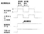
図5に監視ユニットの監視信号と上流の監視ユニットからの状態信号が正常状態を示す場合の信号波形を示す。なお、ここでは、状態信号が伝達する電池状態の相違による消費電力のばらつきを解消するための手段を簡潔に説明するため、フォトカプラによる消費電力のばらつきについては考慮しない。
In the first embodiment, the final monitoring result signal is sent from the most downstream monitoring unit Un → the relay monitoring unit U (n−1) → the relay monitoring unit U via the state transmission circuit I / F and the final monitoring result transmission means 26. (N-2) → ... → relay monitoring unit U (n-1) → upstreammost monitoring unit U1 is transmitted in this order, but without providing the state transmission circuit I / F and the final monitoring result transmission means 26. The microcomputer that has received the final monitoring result signal may transmit the final monitoring result signal via the
(Example 2)
FIG. 5 shows signal waveforms when the monitoring signal of the monitoring unit and the status signal from the upstream monitoring unit indicate a normal state. It should be noted that here, in order to briefly explain the means for eliminating the variation in power consumption due to the difference in battery state transmitted by the state signal, the variation in power consumption due to the photocoupler is not considered.
図5の一番上の信号波形は指示信号の波形を示すものである。指示信号は、監視ユニットUの制御を司る制御部から送信されるものであって、監視ユニットUに対して電池状態の監視を指示する。指示信号がHレベルの場合、監視ユニットUは監視対象のブロックが過放電状態か否かを監視する過放電検出モードとなり、指示信号がLレベルの場合、監視ユニットUは監視対象のブロックが過充電か否かを監視する過充電検出モードとなる。 The top signal waveform in FIG. 5 shows the waveform of the instruction signal. The instruction signal is transmitted from the control unit that controls the monitoring unit U, and instructs the monitoring unit U to monitor the battery state. When the instruction signal is at the H level, the monitoring unit U enters an overdischarge detection mode for monitoring whether or not the monitored block is in an overdischarged state. When the instruction signal is at the L level, the monitoring unit U has exceeded the monitored block. The overcharge detection mode for monitoring whether or not charging is performed.
図5の上から2番目の信号波形は隣接する上流の監視ユニットの状態信号である入力信号の波形を示す。過放電検出モードの場合、Hレベルの信号は上流の監視ユニットにおいて過放電のブロックを検出していないことを示し、Lレベルの信号は上流の監視ユニットにおいて過放電のブロックが検出されたことを示す。過充電検出モードは、逆となり、Lレベルの信号は上流の監視ユニットにおいて過充電のブロックを検出していないことを示し、Hレベルの信号は上流の監視ユニットにおいて過充電のブロックが検出されたことを示す。 The second signal waveform from the top in FIG. 5 shows the waveform of the input signal which is the status signal of the adjacent upstream monitoring unit. In the overdischarge detection mode, an H level signal indicates that no overdischarge block has been detected in the upstream monitoring unit, and an L level signal indicates that an overdischarge block has been detected in the upstream monitoring unit. Show. The overcharge detection mode is reversed, the L level signal indicates that no overcharge block has been detected in the upstream monitoring unit, and the H level signal has detected an overcharge block in the upstream monitoring unit. It shows that.
図5の下から2番目の信号波形は、監視信号の信号波形を示す。この場合も、入力信号の場合と同様であり、過放電検出モードの場合、Hレベルの信号は自身の監視ユニットにおいて過放電のブロックを検出していないことを示し、Lレベルの信号は自身の監視ユニットにおいて過放電のブロックが検出されたことを示す。過充電検出モードは、逆となり、Lレベルの信号は自身の監視ユニットにおいて過充電のブロックを検出していないことを示し、Hレベルの信号は自身の監視ユニットにおいて過充電のブロックが検出されたことを示す。 The second signal waveform from the bottom in FIG. 5 shows the signal waveform of the monitoring signal. This case is the same as the case of the input signal. In the overdischarge detection mode, the H level signal indicates that the overdischarge block is not detected in its own monitoring unit, and the L level signal is Indicates that an overdischarge block has been detected in the monitoring unit. The overcharge detection mode is reversed, an L level signal indicates that no overcharge block has been detected in its own monitoring unit, and an H level signal has detected an overcharge block in its own monitoring unit. It shows that.
図5の一番下の信号波形は、監視ユニットUから出力される状態信号を示す。過放電検出モードの場合、Hレベルの信号は自身の監視ユニットUと上流の監視ユニットにおいて過放電のブロックを検出していないことを示し、Lレベルの信号は自身の監視ユニットU及び上流の監視ユニットの少なくとも一方において過放電のブロックが検出されたことを示す。過充電検出モードは、逆となり、Lレベルの信号は自身の監視ユニットUと上流の監視ユニットにおいて過充電のブロックを検出していないことを示し、Hレベルの信号は自身の監視ユニットUと上流の監視ユニットの少なくとも一方において過充電のブロックが検出されたことを示す。 The signal waveform at the bottom of FIG. 5 shows the status signal output from the monitoring unit U. In the overdischarge detection mode, an H level signal indicates that an overdischarge block is not detected in its own monitoring unit U and upstream monitoring unit, and an L level signal indicates its own monitoring unit U and upstream monitoring. Indicates that an overdischarge block has been detected in at least one of the units. The overcharge detection mode is reversed, and an L level signal indicates that an overcharge block is not detected in its own monitoring unit U and upstream monitoring unit, and an H level signal indicates that its own monitoring unit U and upstream. This indicates that an overcharge block has been detected in at least one of the monitoring units.
このように、指示信号、状態信号及び監視信号は電圧又は電流の大きさに基づくレベル(HレベルやLレベル)によって信号の状態を表している。過放電検出モードの場合、監視ユニットUからの出力信号として出力される状態信号のレベルは監視ユニットUへ入力信号として入力される状態信号のレベル以上となる。過充電検出モードの場合、監視ユニットUからの出力信号として出力される状態信号のレベルは監視ユニットUへ入力信号として入力される状態信号のレベル以下となる。監視ユニットUからの出力信号として出力される状態信号のレベルと、監視ユニットUへ入力信号として入力される状態信号のレベルが異なる場合には、出力ラインと入力ラインとで、状態信号を伝達するために要する電力が異なってしまう。この結果、生じる消費電力のばらつきのメカニズムと当該ばらつきを均等化する手法について以下説明する。 As described above, the instruction signal, the status signal, and the monitoring signal indicate the signal status by the level (H level or L level) based on the magnitude of the voltage or current. In the overdischarge detection mode, the level of the state signal output as an output signal from the monitoring unit U is equal to or higher than the level of the state signal input as an input signal to the monitoring unit U. In the overcharge detection mode, the level of the state signal output as an output signal from the monitoring unit U is equal to or lower than the level of the state signal input as an input signal to the monitoring unit U. When the level of the status signal output as the output signal from the monitoring unit U is different from the level of the status signal input as the input signal to the monitoring unit U, the status signal is transmitted between the output line and the input line. The electric power required for this will differ. As a result, a mechanism of variation in power consumption and a method for equalizing the variation will be described below.
図6に監視ユニットの監視信号が過放電を示し、上流の監視ユニットからの状態信号が正常状態を示す場合の信号波形を示す。 FIG. 6 shows a signal waveform when the monitoring signal of the monitoring unit indicates overdischarge and the status signal from the upstream monitoring unit indicates a normal state.
図6の一番下の信号波形と下から2番目の信号波形が示すように、過放電が発生すると、監視信号と状態信号は、常にLレベルの信号となる。この結果、入力信号はHレベルである場合でも、出力信号ではLレベルとなり、当該監視ユニットUの入力ラインで消費される電力は当該監視ユニットUの出力ラインで消費される電力よりも大きくなる。この結果、当該監視ユニットU以降では、消費電力が小さくなり、ブロック間の電池ばらつきの要因となる。 As shown in the bottom signal waveform and the second signal waveform from the bottom in FIG. 6, when overdischarge occurs, the monitor signal and the status signal are always L level signals. As a result, even when the input signal is at the H level, the output signal is at the L level, and the power consumed by the input line of the monitoring unit U is larger than the power consumed by the output line of the monitoring unit U. As a result, in the monitoring unit U and later, power consumption is reduced, which causes battery variations between blocks.
図7に監視ユニットの監視信号が過充電を示し、上流の監視ユニットからの状態信号が正常状態を示す場合の信号波形を示す。 FIG. 7 shows a signal waveform when the monitoring signal of the monitoring unit indicates overcharge and the state signal from the upstream monitoring unit indicates a normal state.
図7の一番下の信号波形と下から2番目の信号波形が示すように、過充電が発生すると、監視信号と状態信号は、常にHレベルの信号となる。この結果、入力信号はLレベルである場合でも、出力信号ではHレベルとなり、当該監視ユニットUの入力ラインで消費される電力は当該監視ユニットUの出力ラインで消費される電力よりも小さくなる。この結果、当該監視ユニットUよりも上流の監視ユニットでは、消費電力が小さくなり、ブロック間の電池ばらつきの要因となる。 As shown in the bottom signal waveform and the second signal waveform from the bottom in FIG. 7, when overcharge occurs, the monitoring signal and the status signal are always H level signals. As a result, even when the input signal is at the L level, the output signal is at the H level, and the power consumed by the input line of the monitoring unit U is smaller than the power consumed by the output line of the monitoring unit U. As a result, in the monitoring unit upstream of the monitoring unit U, power consumption is reduced, which causes battery variation between blocks.
図8に本発明の実施例2におけるフローチャート、図9に本発明の実施例2における過放電検出モードにおける各ブロックの放電の様子、図10に本発明の実施例2における過充電検出モードにおける各ブロックの放電の様子を示す。 FIG. 8 is a flowchart in the second embodiment of the present invention, FIG. 9 is a state of discharge of each block in the overdischarge detection mode in the second embodiment of the present invention, and FIG. 10 is each flowchart in the overcharge detection mode in the second embodiment of the present invention. The state of discharge of a block is shown.
図8について説明する。最初にステップ100において、過充電検出モードか過放電検出モードか判定する。過放電検出モードの場合、ステップ120に移行し、過充電検出モードの場合、ステップ110に移行する。ステップ110では、最終監視結果信号を取得し、最終監視結果信号がHighレベルか否か判定する。過充電検出モードにおいて最終監視結果信号がLowレベルを示す場合、すべてのブロックにおいて状態信号がLowレベルであり、状態信号の伝達による消費電力のばらつきは生じない。従って、最終監視結果信号がLowレベルの場合は、判定を終了する。一方、最終監視結果信号がHighレベルの場合、ステップ120に移行し、放電判定を行っている監視ユニットUの状態信号がLowレベルか否か判定する。Highレベルの場合、最下流監視ユニットと放電判定を行っている監視ユニットとの状態信号伝達に要する消費電力は等しいため、何も行わず、処理を終了する。一方、Lowレベルの場合、最下流監視ユニットUnよりも状態信号の伝達に要する消費電力が小さいため、放電回路24を放電する。このときの放電量は、Highレベルの状態信号を伝達する場合の消費電力に相当する。
FIG. 8 will be described. First, in
図9を用いて、過放電検出モードにおける放電回路の放電の様子を説明する。図9では、監視ユニットU4において、過放電が検出される。正常時はHレベルの状態信号を伝達し、過放電時はLレベルの状態信号を伝達するため、監視ユニットU1〜U3は、監視ユニットU4〜U6と比べて、放電量が多くなる。そのため、監視ユニットU4〜U6は、放電回路24を放電させて、監視ユニットU1〜U6における消費電力を均一化する。
The state of discharge of the discharge circuit in the overdischarge detection mode will be described with reference to FIG. In FIG. 9, overdischarge is detected in the monitoring unit U4. Since the H level state signal is transmitted during normal operation and the L level state signal is transmitted during overdischarge, the monitoring units U1 to U3 have a larger discharge amount than the monitoring units U4 to U6. Therefore, the monitoring units U4 to U6 discharge the
このように、図9では、監視ユニットからの出力信号として状態信号のレベルと、監視ユニットへ入力信号として入力される状態信号のレベルが異なる特定の監視ユニットとして監視ユニットU4を検知する。図9では、監視ユニットU4の出力信号のレベルが前記入力信号のレベルよりも小さい場合に該当し、監視ユニットU4の放電回路24と前記監視ユニットU4よりも下流に位置する監視ユニットU5,U6の放電回路24とを放電する。なお、図8のフローチャートは、最上流監視ユニットU1の状態信号がLレベルの場合に、最上流監視ユニットU1の放電回路24を放電する。ただし、過放電検出モードにおいて、最上流監視ユニットU1がLレベルの状態信号を伝達する場合は、全ての監視ユニットU1〜UnがLレベルの状態信号を伝達することになるので、最上流監視ユニットU1の状態信号がLレベルの場合は、全監視ユニットU1〜Unは放電を行わないという処理を行っても、もちろん問題はない。
As described above, in FIG. 9, the monitoring unit U4 is detected as a specific monitoring unit in which the level of the state signal as the output signal from the monitoring unit is different from the level of the state signal input as the input signal to the monitoring unit. In FIG. 9, this corresponds to the case where the level of the output signal of the monitoring unit U4 is smaller than the level of the input signal, and the
一方、過充電検出モードにおける放電回路24の放電の様子は図10を用いて説明する。図10では、監視ユニットU4において、過充電が検出される。正常時はLレベルの状態信号を伝達し、過充電時はHレベルの状態信号を伝達するため、監視ユニットU1〜U3は、監視ユニットU4〜U6と比べて、放電量が少なくなる。監視ユニットUは自分よりも下流に位置する監視ユニットの状態信号の状態がわからないため、最下流監視ユニットUnの状態信号である最終監視結果信号を下流から上流に向けて伝達させ、最終監視結果信号と放電判定を行う監視ユニットの状態信号を比較して、放電の要否を判断する。図10の場合、最終監視結果信号よりも低いレベルの状態信号を有する監視ユニットU1〜U3が、放電回路24を放電させて、監視ユニットU1〜U6における消費電力を均一化することとなる。
On the other hand, the discharge state of the
このように、図10では、監視ユニットUからの出力信号として状態信号のレベルと、監視ユニットUへ入力信号として入力される状態信号のレベルが異なる特定の監視ユニットとして監視ユニットU4を検知する。図10では、監視ユニットU4の出力信号のレベルが前記入力信号のレベルよりも大きい場合に該当し、監視ユニットU4よりも上流に位置する監視ユニットU1〜U3の放電回路24を放電する。
As described above, in FIG. 10, the monitoring unit U4 is detected as a specific monitoring unit in which the level of the state signal as the output signal from the monitoring unit U is different from the level of the state signal input as the input signal to the monitoring unit U. In FIG. 10, this corresponds to the case where the level of the output signal of the monitoring unit U4 is higher than the level of the input signal, and the
状態信号が伝達する電池状態の相違による消費電力のばらつきを解消するための放電回路24は、フォトカプラによる消費電量のばらつきを解消するための放電回路24と共用してもよいし、フォトカプラによる消費電量のばらつきを解消するための放電回路24と並列に新しく放電回路24を設けてもよい。
The
なお、上記の実施例1および実施例2には、以下の機能を付け加えてもよい。 In addition, you may add the following functions to said Example 1 and Example 2. FIG.
指示信号に全放電指令を示す情報を含ませて、監視ユニットUが全放電指令を示す指示信号に応じて放電回路24を放電するようにもできる。過充電状態になっているにも関わらず、充電を停止できない等の充電異常が生じた場合に、全放電指令を行うことで、充電異常の影響を軽減でき、フェールセーフの役割を果たすことができる。
Information indicating the total discharge command may be included in the instruction signal so that the monitoring unit U can discharge the
指示信号に、監視ユニットとブロックの診断指示を示す情報を更に含ませてもよい。この場合、監視ユニットは、診断指示に応じて放電回路24を放電して監視対象のブロックの充電状態の変化量を測定する。そして、その変化量に基づいて監視ユニットU又は監視対象のブロックBLに異常があるか否かを判定する。例えば、変化量がない場合には、監視ユニットUの放電機能に異常があると判断でき、変化量が規定値と比べて極めて大きい場合には、監視対象のブロックに異常があると判断できる。
The instruction signal may further include information indicating a diagnostic instruction for the monitoring unit and the block. In this case, the monitoring unit discharges the
上記実施例においては、高電位側を上流、低電位側を下流と定義したが、低電位側を上流、高電位側を下流としてもよい。 In the above embodiment, the high potential side is defined as upstream and the low potential side is defined as downstream. However, the low potential side may be defined as upstream and the high potential side may be defined as downstream.
1 組電池監視装置
10 組電池
21 上流の絶縁素子(上流フォトカプラ)
22 下流の絶縁素子(下流フォトカプラ)
23 監視手段
24 放電手段(放電回路)
25 合成手段
26 最終監視結果伝達手段
B、B11〜Bnm セル
BL、BL1〜BLn ブロック
U、U1〜Un 監視ユニット
1 assembled
22 Downstream insulation element (downstream photocoupler)
23 monitoring means 24 discharging means (discharge circuit)
25 Combining means 26 Final monitoring result transmitting means B, B11 to Bnm Cell BL, BL1 to BLn Block U, U1 to Un Monitoring unit
Claims (7)
最も上流に位置する最上流監視ユニットは、前記監視ユニットに対して電池状態の監視を指示する制御部からの指示信号を上流の絶縁素子を介して受け取り、最も下流に位置する最下流監視ユニットは、全ブロックの監視結果を示す最終監視結果信号を下流の絶縁素子を介して前記制御部へ送り、前記最上流監視ユニットと前記最下流監視ユニットとの間に位置する中継監視ユニットは、上流の監視ユニットから伝達された前記上流の監視ユニットの監視結果に前記中継監視ユニットの監視結果を反映させた状態信号を下流の監視ユニットに伝達するものであって、
前記最上流監視ユニットと前記中継監視ユニットは、前記下流の絶縁素子の通電状態に応じて監視対象のブロックを放電する放電手段を有することを特徴とする組電池監視装置。 Constructed as a series connection body of monitoring units that monitor the state of charge of the cell for each block unit, with respect to an assembled battery formed by connecting a plurality of blocks composed of a single cell or a series connection body of a plurality of cells in series. In the assembled battery monitoring device
The most upstream monitoring unit located at the most upstream receives an instruction signal from the control unit that instructs the monitoring unit to monitor the battery state via the upstream insulating element, and the most downstream monitoring unit located at the most downstream side The final monitoring result signal indicating the monitoring results of all blocks is sent to the control unit via the downstream insulating element, and the relay monitoring unit located between the most upstream monitoring unit and the most downstream monitoring unit A status signal reflecting the monitoring result of the relay monitoring unit in the monitoring result of the upstream monitoring unit transmitted from the monitoring unit is transmitted to the downstream monitoring unit;
The assembled battery monitoring apparatus, wherein the most upstream monitoring unit and the relay monitoring unit include discharge means for discharging a block to be monitored in accordance with an energization state of the downstream insulating element.
前記監視ユニットからの出力信号として出力される状態信号のレベルと、前記監視ユニットへ入力信号として入力される状態信号のレベルが異なる特定の監視ユニットを検知し、
前記出力信号のレベルが前記入力信号のレベルよりも大きい場合に、前記特定の監視ユニットよりも上流に位置する監視ユニットの放電手段を放電し、
前記出力信号のレベルが前記入力信号のレベルよりも小さい場合に、前記特定の監視ユニットの放電手段と前記監視ユニットよりも下流に位置する放電手段とを放電することを特徴とする請求項1ないし4のいずれか1項に記載の組電池監視装置。 The state signal represents the state of the signal by a level based on the magnitude of voltage or current,
Detecting a specific monitoring unit in which the level of the status signal output as an output signal from the monitoring unit is different from the level of the status signal input as an input signal to the monitoring unit;
When the level of the output signal is greater than the level of the input signal, the discharging means of the monitoring unit located upstream from the specific monitoring unit is discharged,
The discharge means of the specific monitoring unit and the discharge means located downstream of the monitoring unit are discharged when the level of the output signal is smaller than the level of the input signal. The assembled battery monitoring device according to any one of 4.
Priority Applications (1)
| Application Number | Priority Date | Filing Date | Title |
|---|---|---|---|
| JP2008189090A JP4905419B2 (en) | 2008-07-22 | 2008-07-22 | Battery monitoring device |
Applications Claiming Priority (1)
| Application Number | Priority Date | Filing Date | Title |
|---|---|---|---|
| JP2008189090A JP4905419B2 (en) | 2008-07-22 | 2008-07-22 | Battery monitoring device |
Publications (2)
| Publication Number | Publication Date |
|---|---|
| JP2010025824A true JP2010025824A (en) | 2010-02-04 |
| JP4905419B2 JP4905419B2 (en) | 2012-03-28 |
Family
ID=41731790
Family Applications (1)
| Application Number | Title | Priority Date | Filing Date |
|---|---|---|---|
| JP2008189090A Active JP4905419B2 (en) | 2008-07-22 | 2008-07-22 | Battery monitoring device |
Country Status (1)
| Country | Link |
|---|---|
| JP (1) | JP4905419B2 (en) |
Cited By (8)
| Publication number | Priority date | Publication date | Assignee | Title |
|---|---|---|---|---|
| JP2012021931A (en) * | 2010-07-16 | 2012-02-02 | Toyota Motor Corp | Abnormality detection device for battery pack |
| JP2012161182A (en) * | 2011-02-01 | 2012-08-23 | Denso Corp | Battery monitoring device |
| KR101206362B1 (en) | 2010-11-19 | 2012-11-30 | 주식회사 포스코아이씨티 | Battery Energy Storage System |
| JP2013088233A (en) * | 2011-10-17 | 2013-05-13 | Denso Corp | Battery monitoring device |
| WO2015087487A1 (en) * | 2013-12-10 | 2015-06-18 | 三洋電機株式会社 | Battery management device and power supply device |
| JP2015192579A (en) * | 2014-03-28 | 2015-11-02 | パナソニックIpマネジメント株式会社 | storage battery system and power consumption control method |
| JP2017055631A (en) * | 2015-09-11 | 2017-03-16 | 株式会社デンソー | Battery pack control device |
| JP2017112697A (en) * | 2015-12-15 | 2017-06-22 | 株式会社デンソー | Battery pack control device |
Citations (1)
| Publication number | Priority date | Publication date | Assignee | Title |
|---|---|---|---|---|
| JP2007282413A (en) * | 2006-04-10 | 2007-10-25 | Denso Corp | Management system of packed battery |
-
2008
- 2008-07-22 JP JP2008189090A patent/JP4905419B2/en active Active
Patent Citations (1)
| Publication number | Priority date | Publication date | Assignee | Title |
|---|---|---|---|---|
| JP2007282413A (en) * | 2006-04-10 | 2007-10-25 | Denso Corp | Management system of packed battery |
Cited By (12)
| Publication number | Priority date | Publication date | Assignee | Title |
|---|---|---|---|---|
| JP2012021931A (en) * | 2010-07-16 | 2012-02-02 | Toyota Motor Corp | Abnormality detection device for battery pack |
| KR101206362B1 (en) | 2010-11-19 | 2012-11-30 | 주식회사 포스코아이씨티 | Battery Energy Storage System |
| JP2012161182A (en) * | 2011-02-01 | 2012-08-23 | Denso Corp | Battery monitoring device |
| JP2013088233A (en) * | 2011-10-17 | 2013-05-13 | Denso Corp | Battery monitoring device |
| WO2015087487A1 (en) * | 2013-12-10 | 2015-06-18 | 三洋電機株式会社 | Battery management device and power supply device |
| CN105940313A (en) * | 2013-12-10 | 2016-09-14 | 三洋电机株式会社 | Battery management device and power supply device |
| JPWO2015087487A1 (en) * | 2013-12-10 | 2017-03-16 | 三洋電機株式会社 | Battery management device and power supply device |
| US10056653B2 (en) | 2013-12-10 | 2018-08-21 | Sanyo Electric Co., Ltd. | Battery management device and power supply device |
| CN105940313B (en) * | 2013-12-10 | 2019-09-24 | 三洋电机株式会社 | Cell managing device and power supply device |
| JP2015192579A (en) * | 2014-03-28 | 2015-11-02 | パナソニックIpマネジメント株式会社 | storage battery system and power consumption control method |
| JP2017055631A (en) * | 2015-09-11 | 2017-03-16 | 株式会社デンソー | Battery pack control device |
| JP2017112697A (en) * | 2015-12-15 | 2017-06-22 | 株式会社デンソー | Battery pack control device |
Also Published As
| Publication number | Publication date |
|---|---|
| JP4905419B2 (en) | 2012-03-28 |
Similar Documents
| Publication | Publication Date | Title |
|---|---|---|
| JP4905419B2 (en) | Battery monitoring device | |
| JP5481146B2 (en) | Battery management device, secondary battery device and vehicle | |
| US8614871B2 (en) | Battery system | |
| JP5517398B2 (en) | Power storage system | |
| WO2010038347A1 (en) | Cell equalization circuit and cell power supply device | |
| JP6136679B2 (en) | Power storage device and power path switching device | |
| JP2010279146A (en) | Voltage monitoring apparatus for multiple battery packs | |
| JP2013162635A (en) | Power storage device, power system and electric vehicle | |
| JP5497421B2 (en) | Multi-series lithium ion secondary battery information transmission system | |
| KR101027314B1 (en) | Multi-cell recharging system | |
| JP2013206643A (en) | Relay fusion detector of battery system, and battery system using the same | |
| JP5839047B2 (en) | Surveillance system and vehicle | |
| JP2014107979A (en) | Battery monitoring device | |
| JP2011097820A (en) | Secondary battery device and vehicle | |
| JP2001309563A (en) | Building power supply system and battery device | |
| JP5739005B2 (en) | Power storage device management system | |
| JP5694902B2 (en) | Secondary battery monitoring device | |
| JP4171449B2 (en) | Power supply for vehicle | |
| JP2013092397A (en) | Battery monitoring device | |
| JP5392338B2 (en) | Battery monitoring device | |
| JP5332062B2 (en) | Uninterruptible power supply system and battery charging method | |
| JP2011053179A (en) | Voltage measurement apparatus of multiple battery pack | |
| JPWO2015011801A1 (en) | Battery system monitoring device | |
| JP4758196B2 (en) | Power storage device | |
| JP2009044923A (en) | Power supply system |
Legal Events
| Date | Code | Title | Description |
|---|---|---|---|
| A621 | Written request for application examination |
Free format text: JAPANESE INTERMEDIATE CODE: A621 Effective date: 20100906 |
|
| A977 | Report on retrieval |
Free format text: JAPANESE INTERMEDIATE CODE: A971007 Effective date: 20110909 |
|
| A131 | Notification of reasons for refusal |
Free format text: JAPANESE INTERMEDIATE CODE: A131 Effective date: 20110920 |
|
| A521 | Request for written amendment filed |
Free format text: JAPANESE INTERMEDIATE CODE: A523 Effective date: 20111109 |
|
| TRDD | Decision of grant or rejection written | ||
| A01 | Written decision to grant a patent or to grant a registration (utility model) |
Free format text: JAPANESE INTERMEDIATE CODE: A01 Effective date: 20111213 |
|
| A01 | Written decision to grant a patent or to grant a registration (utility model) |
Free format text: JAPANESE INTERMEDIATE CODE: A01 |
|
| A61 | First payment of annual fees (during grant procedure) |
Free format text: JAPANESE INTERMEDIATE CODE: A61 Effective date: 20111226 |
|
| FPAY | Renewal fee payment (event date is renewal date of database) |
Free format text: PAYMENT UNTIL: 20150120 Year of fee payment: 3 |
|
| R151 | Written notification of patent or utility model registration |
Ref document number: 4905419 Country of ref document: JP Free format text: JAPANESE INTERMEDIATE CODE: R151 |
|
| FPAY | Renewal fee payment (event date is renewal date of database) |
Free format text: PAYMENT UNTIL: 20150120 Year of fee payment: 3 |
|
| R250 | Receipt of annual fees |
Free format text: JAPANESE INTERMEDIATE CODE: R250 |
|
| R250 | Receipt of annual fees |
Free format text: JAPANESE INTERMEDIATE CODE: R250 |
|
| R250 | Receipt of annual fees |
Free format text: JAPANESE INTERMEDIATE CODE: R250 |
|
| R250 | Receipt of annual fees |
Free format text: JAPANESE INTERMEDIATE CODE: R250 |
|
| R250 | Receipt of annual fees |
Free format text: JAPANESE INTERMEDIATE CODE: R250 |
|
| R250 | Receipt of annual fees |
Free format text: JAPANESE INTERMEDIATE CODE: R250 |
|
| R250 | Receipt of annual fees |
Free format text: JAPANESE INTERMEDIATE CODE: R250 |
|
| R250 | Receipt of annual fees |
Free format text: JAPANESE INTERMEDIATE CODE: R250 |
|
| R250 | Receipt of annual fees |
Free format text: JAPANESE INTERMEDIATE CODE: R250 |