JP2010025725A - Wavelength dispersion measuring device and method for measuring wavelength dispersion - Google Patents
Wavelength dispersion measuring device and method for measuring wavelength dispersion Download PDFInfo
- Publication number
- JP2010025725A JP2010025725A JP2008186856A JP2008186856A JP2010025725A JP 2010025725 A JP2010025725 A JP 2010025725A JP 2008186856 A JP2008186856 A JP 2008186856A JP 2008186856 A JP2008186856 A JP 2008186856A JP 2010025725 A JP2010025725 A JP 2010025725A
- Authority
- JP
- Japan
- Prior art keywords
- chromatic dispersion
- light
- medium
- component
- frequency
- Prior art date
- Legal status (The legal status is an assumption and is not a legal conclusion. Google has not performed a legal analysis and makes no representation as to the accuracy of the status listed.)
- Granted
Links
Images


Abstract
Description
本発明は、光ファイバや光部品の基本特性の一つである波長分散値を測定する波長分散測定装置及び波長分散測定方法に関するものである。 The present invention relates to a chromatic dispersion measuring apparatus and a chromatic dispersion measuring method for measuring a chromatic dispersion value which is one of basic characteristics of optical fibers and optical components.
光通信システムを構築する光ファイバや光部品の基本特性の一つである波長分散は、光通信システムにおける光信号の伝送特性に大きな影響を与える。この波長分散による光通信システムの特性劣化を抑制するためには、光ファイバや光部品の波長分散を正確に測定する技術がまず必要とされる。一方、通信容量の拡大への需要の高まりから、1.0μm帯等、これまで利用されてきた通信波長帯以外の波長帯を新規に開拓する試みが進められている(下記非特許文献1参照)。このような新規波長帯についても波長分散測定技術が確立することが望まれる。
Chromatic dispersion, which is one of the basic characteristics of optical fibers and optical components that make up an optical communication system, greatly affects the transmission characteristics of optical signals in an optical communication system. In order to suppress the characteristic deterioration of the optical communication system due to the chromatic dispersion, a technique for accurately measuring the chromatic dispersion of the optical fiber or the optical component is first required. On the other hand, due to the growing demand for expansion of communication capacity, an attempt to newly cultivate a wavelength band other than the communication wavelength band that has been used so far, such as the 1.0 μm band, has been advanced (see Non-Patent
波長分散の測定方法としては、位相シフト法(下記非特許文献2参照)、光パルス法(下記非特許文献3参照)、干渉法(下記非特許文献4参照)のように測定波長をステップ状に掃引して群遅延時間特性を測定し、これを波長で微分することにより波長分散を求める方法がある。しかし、これらの測定法においては、波長掃引可能な光源、又は複数の波長の光源が必要とされ、これは上述の1.0μm帯等、技術的な開拓がまだ十分に行われていない波長帯においては実現が容易でない場合もありうる。 As a method for measuring chromatic dispersion, the measurement wavelength is stepped like a phase shift method (see the following non-patent document 2), an optical pulse method (see the following non-patent document 3), or an interference method (see the following non-patent document 4). There is a method of measuring chromatic dispersion by measuring the group delay time characteristic by sweeping and then differentiating it by wavelength. However, in these measurement methods, a light source capable of wavelength sweeping or a light source having a plurality of wavelengths is required. This is a wavelength band in which technical development has not been sufficiently performed, such as the above-described 1.0 μm band. In some cases, it may not be easy to implement.
波長掃引可能な光源、又は、複数の波長の光源を必要としない波長分散測定法として、ベースバンドAM応答測定法(下記非特許文献5及び下記非特許文献6参照)がある。
下記非特許文献6に示されている、この方法による波長分散測定の構成を図14に示す。
As a wavelength dispersion measurement method that does not require a wavelength-swept light source or a light source having a plurality of wavelengths, there is a baseband AM response measurement method (see Non-Patent
The configuration of chromatic dispersion measurement by this method shown in Non-Patent Document 6 below is shown in FIG.
図14に示すように、本方法においては、光源10から出力された光を強度変調器40により強度変調した際に発生する変調側波帯の位相関係が分散媒体13中の波長分散より変化し、その結果、光の時間波形が変化することを利用する。強度変調周波数を変化させた場合、光の時間波形の強度変調成分が極小値を取る強度変調周波数が周期的に存在する。その周波数の観測を受光器14及びネットワークアナライザ41を用いて行う。強度変調成分が極小値を取る周波数fmは式(1)で与えられる。

ここで、nは極小値の次数(1、2、3、....)、Dは分散媒体の単位長さ当たりの波長分散値、Lは分散媒体長、λは測定波長(光源波長)である。また、強度変調器40のチャープパラメータ(αパラメータ)は0であるとしている。強度変調成分が極小値を取る周波数を測定し、式(1)から波長分散値DLを得ることができる。
Here, n is the order of the minimum value (1, 2, 3,...), D is the chromatic dispersion value per unit length of the dispersion medium, L is the dispersion medium length, and λ is the measurement wavelength (light source wavelength). It is. The chirp parameter (α parameter) of the
一方、波長掃引可能な光源、又は複数の波長の光源を必要としない別の波長分散測定法として、位相変調器を用いる方法が提案されている(下記非特許文献7及び下記特許文献参照)。本方法においては光源からの光が特定の周波数で位相変調を施された後に分散媒体に入射される。分散媒体中では位相変調成分が強度変調成分に変換されるが、その変換の割合が波長分散に依存することを利用して、分散媒体の波長分散を導出するものである。 On the other hand, a method using a phase modulator has been proposed as another wavelength dispersion measurement method that does not require a wavelength-swept light source or a light source having a plurality of wavelengths (see Non-Patent Document 7 and Patent Document below). In this method, light from a light source is incident on a dispersion medium after being subjected to phase modulation at a specific frequency. In the dispersion medium, the phase modulation component is converted into the intensity modulation component, and the chromatic dispersion of the dispersion medium is derived using the fact that the conversion ratio depends on the chromatic dispersion.
下記特許文献1において実施例として示されている波長分散測定装置の構成を図15に示す。
図15に示すように、光源10からの光は外部位相変調器12によって特定の周波数で変調される。位相変調器12は周波数固定で動作させる発振器50により駆動する。また、位相変調器12の出力光の一部を分波器51により分波し、光スペクトラムアナライザ52によって光スペクトルを観測することにより、位相変調の変調指数を求める。
FIG. 15 shows the configuration of a chromatic dispersion measuring apparatus shown as an example in
As shown in FIG. 15, the light from the
分散媒体13を通過した後の位相変調光は分散に応じて一部が強度変調成分に変換されている。そこで、受光器14の出力に含まれる交流成分と直流成分をそれぞれ交流電圧計53、直流電圧計54にて測定し、その強度比を比較器58により求めることによって分散媒体13の波長分散を知ることが可能となる。交流電圧計53の前段にはバンドパスフィルタ55を挿入する。
A part of the phase-modulated light after passing through the
なお、下記特許文献1においては、分散媒体13へ入射する位相変調光の強度を光増幅器56又は可変光減衰器57の設定により変化させ、分散媒体中での自己位相変調の効果を変化させることによって分散媒体の波長分散の符号を特定する方法を提案している。また、下記特許文献1中に記述があるように、下記特許文献1で提案されている波長分散測定法においては、位相変調周波数を固定した状態で波長分散測定が行われる。
In
図14に示した強度変調器40を用いる波長分散測定法(ベースバンドAM応答測定法)においては、光源10の波長と、強度変調成分が極小値を取る周波数の2つの測定値のみから式(1)より波長分散を導出できる。この場合、これらの2つのパラメータは高精度に測定可能であるため、波長分散を正確に導出することが可能である。
In the chromatic dispersion measurement method (baseband AM response measurement method) using the
しかし、式(1)は、強度変調器40のチャープパラメータ(αパラメータ)が0であることを前提としている。実際の強度変調器は有限のαパラメータを有しており、この影響を考慮して波長分散を導出する必要がある。しかしながら、強度変調器40のαパラメータを正確に求めるのは容易でなく、その結果、実際に測定される波長分散値は誤差を含んでしまう。
However, equation (1) assumes that the chirp parameter (α parameter) of the
また、図15に示した位相変調器12を用いる波長分散測定法においては、波長分散を導出するために位相変調指数を正確に測定する必要があり、この位相変調指数の測定誤差が波長分散の測定誤差につながる。また、本方法においては受光器14の出力信号を2分岐して、交流成分と直流成分の比を求める必要があるが、受光部14後の直流電圧計54、交流電圧計53までの系に損失の差がある場合、これが波長分散値の測定誤差につながる。
In the chromatic dispersion measurement method using the
本発明は、上述した事情に鑑みてなされたものであり、連続光を出力する光源と光変調器を利用した波長分散測定装置において、測定誤差を増大させる要因である変調器のαパラメータ、変調指数、測定系の損失の影響を含有せず、高精度な波長分散測定を可能とする波長分散測定装置を提供することを目的とする。 The present invention has been made in view of the above-described circumstances, and in a chromatic dispersion measuring device using a light source that outputs continuous light and an optical modulator, the α parameter of the modulator, which is a factor that increases measurement error, and modulation It is an object of the present invention to provide a chromatic dispersion measuring apparatus that does not include the influence of the index and the loss of the measurement system and enables highly accurate chromatic dispersion measurement.
上記の課題を解決する第1の発明に係る波長分散測定装置は、
被測定媒体の波長分散値を求める波長分散測定装置において、
連続光を発生させる光源と、
周波数掃引可能な正弦波信号を発生する電気信号発生器と、
前記電気信号発生器から出力される正弦波信号によって駆動され、前記光源の出力光に対して位相変調を行う位相変調器と、
前記位相変調器から出力される出力光を、前記被測定媒体に入射した際の出力光を電気信号に変換する受光器と、
前記受光器から出力される電気信号の交流成分の強度を観測する交流成分観測手段と
を具備し、
前記交流成分観測手段により交流成分が極小値を取る周波数を求め、この周波数から被測定媒体の波長分散値を求める
ことを特徴とする。
The chromatic dispersion measuring apparatus according to the first invention for solving the above-mentioned problems is
In the chromatic dispersion measuring device for obtaining the chromatic dispersion value of the measured medium,
A light source that generates continuous light;
An electrical signal generator for generating a frequency sweepable sinusoidal signal;
A phase modulator driven by a sine wave signal output from the electrical signal generator and performing phase modulation on the output light of the light source;
A light receiver that converts the output light output from the phase modulator into an electrical signal when the light is incident on the measured medium; and
AC component observation means for observing the intensity of the AC component of the electrical signal output from the light receiver,
A frequency at which the AC component takes a minimum value is obtained by the AC component observation means, and a chromatic dispersion value of the medium to be measured is obtained from this frequency.
上記の課題を解決する第2の発明に係る波長分散測定装置は、
被測定媒体の波長分散値を求める波長分散測定装置において、
連続光を発生させる光源と、
広帯域な電気雑音成分を発生する雑音発生器と、
前記雑音発生器から出力される電気雑音成分によって駆動され、前記光源の出力光に対して位相変調を行う位相変調器と、
前記位相変調器から出力される出力光を前記被測定媒体に入射した際の出力光を電気信号に変換する受光器と、
前記受光器から出力される電気信号の交流成分の強度を観測する交流成分観測手段と
を具備し、
前記交流成分観測手段により交流成分が極小値を取る周波数を求め、この周波数から被測定媒体の波長分散値を求める
ことを特徴とする。
The chromatic dispersion measuring apparatus according to the second invention for solving the above-mentioned problems is
In the chromatic dispersion measuring device for obtaining the chromatic dispersion value of the measured medium,
A light source that generates continuous light;
A noise generator that generates a wide-band electrical noise component;
A phase modulator driven by an electrical noise component output from the noise generator and performing phase modulation on the output light of the light source;
A light receiver for converting the output light output from the phase modulator into an electric signal when the output light is incident on the measured medium;
AC component observation means for observing the intensity of the AC component of the electrical signal output from the light receiver,
A frequency at which the AC component takes a minimum value is obtained by the AC component observation means, and a chromatic dispersion value of the medium to be measured is obtained from this frequency.
上記の課題を解決する第3の発明に係る波長分散測定装置は、第1の発明又は第2の発明に係る波長分散測定装置において、
前記位相変調器の後段に波長分散値が既知である分散媒体を具備し、
前記位相変調器から出力される出力光を前記波長分散値が既知である分散媒体を通した後に前記被測定媒体に入射した場合と、前記位相変調器から出力される出力光を前記被測定媒体に直接入射した場合との2通りについて前記交流成分観測手段により交流成分が極小値を取る周波数を求め、これらの周波数から前記被測定媒体の波長分散値を符号も含めて求める
ことを特徴とする。
A chromatic dispersion measuring apparatus according to a third invention for solving the above-mentioned problems is the chromatic dispersion measuring apparatus according to the first invention or the second invention.
A dispersion medium having a known chromatic dispersion value is provided after the phase modulator,
When the output light output from the phase modulator passes through the dispersion medium whose chromatic dispersion value is known and then enters the measured medium, and the output light output from the phase modulator is the measured medium The frequency at which the AC component takes a minimum value is obtained by the AC component observation means for the two cases of direct incidence on the light, and the chromatic dispersion value of the measured medium including the sign is obtained from these frequencies. .
上記の課題を解決する第4の発明に係る波長分散測定装置は、第1の発明から第3の発明のいずれかひとつに係る波長分散測定装置において、
前記光源は前記連続光の波長が可変の波長可変光源であり、
前記被測定媒体の波長分散値の波長依存性を測定する
ことを特徴とする。
A chromatic dispersion measuring apparatus according to a fourth invention for solving the above-mentioned problems is the chromatic dispersion measuring apparatus according to any one of the first to third inventions,
The light source is a wavelength variable light source in which the wavelength of the continuous light is variable;
The wavelength dependence of the wavelength dispersion value of the measured medium is measured.
上記の課題を解決する第5の発明に係る波長分散測定方法は、
被測定媒体の波長分散値を求める波長分散測定方法において、
連続光を発生する工程と、
周波数掃引可能な正弦波信号を発生する工程と、
前記正弦波信号を用いて前記連続光に対して位相変調を行う工程と、
位相変調された前記連続光を前記被測定媒体に入射した際の出力光を電気信号に変換する工程と、
前記電気信号の交流成分の強度を観測する工程と、
前記交流成分が極小値を取る周波数を求め、この周波数から被測定媒体の波長分散値を求める工程と
を具備する
ことを特徴とする。
A chromatic dispersion measuring method according to a fifth invention for solving the above-mentioned problems is as follows.
In the chromatic dispersion measuring method for obtaining the chromatic dispersion value of the measured medium,
A process of generating continuous light;
Generating a frequency sweepable sinusoidal signal;
Performing phase modulation on the continuous light using the sine wave signal;
Converting the output light when the phase-modulated continuous light is incident on the measured medium into an electrical signal;
Observing the intensity of the alternating current component of the electrical signal;
Obtaining a frequency at which the AC component takes a minimum value, and obtaining a chromatic dispersion value of the medium to be measured from this frequency.
上記の課題を解決する第6の発明に係る波長分散測定方法は、
被測定媒体の波長分散値を求める波長分散測定方法において、
連続光を発生させる工程と、
広帯域な電気雑音成分を発生させる工程と、
前記電気雑音成分を用いて前記連続光に対して位相変調を行う工程と、
位相変調された前記連続光を前記被測定媒体に入射した際の出力光を電気信号に変換する工程と、
前記電気信号の交流成分の強度を観測する工程と、
前記交流成分が極小値を取る周波数を求め、この周波数から被測定媒体の波長分散値を求める工程と
を具備する
ことを特徴とする。
A chromatic dispersion measuring method according to a sixth invention for solving the above-described problems is as follows.
In the chromatic dispersion measuring method for obtaining the chromatic dispersion value of the measured medium,
A step of generating continuous light;
Generating a wide-band electrical noise component;
Performing phase modulation on the continuous light using the electrical noise component;
Converting the output light when the phase-modulated continuous light is incident on the measured medium into an electrical signal;
Observing the intensity of the alternating current component of the electrical signal;
Obtaining a frequency at which the AC component takes a minimum value, and obtaining a chromatic dispersion value of the medium to be measured from this frequency.
上記の課題を解決する第7の発明に係る波長分散測定方法は、第5の発明又は第6の発明に係る波長分散測定方法において、
位相変調された前記連続光を波長分散値が既知である分散媒体を通す工程と、
位相変調された前記連続光を前記分散媒体を通した後に前記被測定媒体に入射した場合と、位相変調された前記連続光を前記被測定媒体に直接入射した場合との2通りについて交流成分が極小値を取る周波数を求め、これらの周波数から前記被測定媒体の波長分散値を符号も含めて求める工程と
を具備する
ことを特徴とする。
A chromatic dispersion measuring method according to a seventh invention for solving the above-mentioned problems is the chromatic dispersion measuring method according to the fifth invention or the sixth invention,
Passing the phase-modulated continuous light through a dispersion medium having a known chromatic dispersion value;
The AC component is divided into two types: a case where the phase-modulated continuous light passes through the dispersion medium and then enters the medium to be measured, and a case where the phase-modulated continuous light directly enters the medium to be measured. And obtaining a frequency having a minimum value and obtaining a chromatic dispersion value of the measured medium including a sign from these frequencies.
上記の課題を解決する第8の発明に係る波長分散測定方法は、第5の発明から第6の発明のいずれかひとつに係る波長分散測定方法において、
前記連続光は波長を可変とし、
前記被測定媒体の波長分散値の波長依存性を測定する
ことを特徴とする。
A chromatic dispersion measuring method according to an eighth invention for solving the above-described problem is the chromatic dispersion measuring method according to any one of the fifth to sixth inventions,
The continuous light has a variable wavelength,
The wavelength dependence of the wavelength dispersion value of the measured medium is measured.
本発明により、変調器のαパラメータ、変調指数、測定系の損失といった測定誤差を増大させる要因の影響を含まず、変調周波数のみから波長分散を高精度に導出できる波長分散測定装置を提供することが可能となる。 According to the present invention, there is provided a chromatic dispersion measuring apparatus capable of deriving chromatic dispersion with high accuracy only from a modulation frequency without including the influence of factors that increase measurement errors such as an α parameter of a modulator, a modulation index, and a measurement system loss. Is possible.
以下、本発明に係る波長分散測定装置及び波長分散測定方法の実施例について、図面を参照して詳細に説明する。 Hereinafter, embodiments of a wavelength dispersion measuring apparatus and a wavelength dispersion measuring method according to the present invention will be described in detail with reference to the drawings.
本発明に係る波長分散測定装置及び波長分散測定方法の第1の実施例について説明する。
図1は本実施例に係る波長分散測定装置の一例を示す構成図、図2は位相変調直後、及び分散媒体出力において位相変調光が強度変調成分を持たなくなる条件における各変調側波帯の位相相関を模式的に示した説明図、図3は分散媒体出力において位相変調光が強度変調成分を持たなくなる条件における各変調側波帯の位相相関を模式的に示した説明図、図4は分散媒体出力での光の時間波形の計算結果を示すグラフ、図5は受光器出力における交流成分強度と周波数の相関の計算結果を示すグラフ、図6は本実施例に係る波長分散方法の手順を説明するフローチャートである。
A first embodiment of a wavelength dispersion measuring apparatus and a wavelength dispersion measuring method according to the present invention will be described.
FIG. 1 is a block diagram showing an example of a chromatic dispersion measuring apparatus according to the present embodiment. FIG. 2 shows the phase of each modulation sideband immediately after phase modulation and under the condition that the phase modulated light has no intensity modulation component at the output of the dispersion medium. FIG. 3 is an explanatory diagram schematically showing the correlation, FIG. 3 is an explanatory diagram schematically showing the phase correlation of each modulation sideband under the condition that the phase modulated light has no intensity modulation component at the output of the dispersion medium, and FIG. 5 is a graph showing the calculation result of the time waveform of light at the medium output, FIG. 5 is a graph showing the calculation result of the correlation between the AC component intensity and the frequency at the receiver output, and FIG. 6 is the procedure of the wavelength dispersion method according to this embodiment. It is a flowchart to explain.
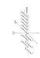
図1に示すように、本実施例に係る波長分散測定装置においては、まず光源10から出力される単一波長の連続光に対し任意の変調指数の正弦波位相変調を位相変調器12により施した後に、分散媒体13に入射する。位相変調器12は周波数可変発振器11出力の正弦波信号により駆動される。
As shown in FIG. 1, in the chromatic dispersion measuring apparatus according to the present embodiment, a sine wave phase modulation having an arbitrary modulation index is first performed by a
分散媒体13の出力を受光器14で電気信号に変換し、スペクトラムアナライザ15により交流成分を観測する。位相変調器12直後の光は正弦波状にチャープした連続光であるが、分散媒体13中において位相変調−強度変調変換により強度変調成分が発生する。
The output of the
ここで、周波数可変発振器11出力の正弦波信号周波数を掃引させると、分散媒体出力光の時間波形が強度変調成分を持たない、すなわち連続光になる変調周波数が存在する。そして、この変調周波数の値のみから分散媒体13の波長分散を直接導出することが可能となる。
Here, when the sinusoidal signal frequency output from the
上記の動作を順を追って説明する。光源10出力の連続光の光周波数及び電界振幅をそれぞれω0、E0とする。このとき連続光の電界は式(2)で表わされる。
![]()
![]()
この連続光に対して位相変調器12により正弦波位相変調を施すと、位相変調器12出力における光の電界は式(3)で表わされる。
すなわち、式(3)はJn(Δθ)で表わされる振幅を有する変調側波帯の電界が角周波数間隔2πfmで発生することを示している。nの絶対値は元の連続光から離れるにしたがって大きくなり、その符号はもとの連続光周波数より高周波側が正となる。
When sinusoidal phase modulation is performed on the continuous light by the
That is, Equation (3) shows that the electric field of modulation sidebands having an amplitude represented by J n ([Delta] [theta]) is generated at the angular frequency interval 2 [pi] f m. The absolute value of n increases as the distance from the original continuous light increases, and the sign is positive on the higher frequency side than the original continuous light frequency.
図2に位相変調により発生する変調側波帯の位相相関をt=0の場合について模式的に示す。図2中のEnはn番目の変調側波帯を表している。なお、実際の変調側波帯の振幅はE0・Jn(Δθ)で与えられ、それらはおのおの異なった大きさを有しているが、図2では簡略化のためにこの振幅偏差を無視している。 FIG. 2 schematically shows the phase correlation of the modulation sideband generated by the phase modulation when t = 0. E n in FIG. 2 represents the n-th modulation sidebands. The actual amplitude of the modulation sideband is given by E 0 · J n (Δθ), and they have different sizes, but in FIG. 2, this amplitude deviation is ignored for simplification. is doing.
図2のIm{E}−Re{E}平面上におけるEnのRe{E}軸からの角度が、Enの相対的な位相を示している。nが負の奇数である場合Jn(Δθ)は負の値を取り、それ以外のnの値についてはJn(Δθ)は正の値を取る。このため、図2に示されるようにnが負の奇数である場合の変調側波帯は他の変調側波帯と位相がπずれている。
Angle from Re {E} axis E n in the Im {E} -Re {E}
位相変調器12出力の光を分散媒体13に入射すると、おのおのの変調側波帯は波長分散による位相変化を受け、その結果、位相変調−強度変調変換が起こり、強度変調成分が発生する。分散媒体13の群速度分散値と長さをそれぞれβ2、Lとすると、分散媒体13後の光の電界は式(4)で表わされる。
t=0の場合について考えると、式(4)より、β2Lの群速度分散を有する分散媒体13を通過することによる各変調側波帯の位相変化は、図2のIm{E}−Re{E}平面を2π2n2(fm 2β2L)だけ回転することに相当する。すなわち、群速度分散により各変調側波帯が受ける相対的な位相変化量はn2に比例する。ここで、n=±1の場合、すなわちE±1の変調側波帯について考えると、この変調側波帯がβ2Lの群速度分散を有する分散媒体13を通過後に受ける位相変化量は2π2(fm 2β2L)となる。
Considering the case of t = 0, from Equation (4), the phase change of each modulation sideband caused by passing through the
この位相変化量がπの偶数倍となる場合、すなわちkを自然数として以下の式(5)が成り立つ場合、各変調側波帯の位相は図2に示すような相関関係に戻る。
![]()
![]()
ここで、式(5)をfmについて解くと、以下の式(6)が得られる。
![]()
![]()
一方、位相変化量2π2(fm 2β2L)がπの奇数倍となる場合、すなわちkを自然数として以下の式(7)が成り立つ場合、各変調側波帯の位相は図3に示すような相関関係になる。
ここで、式(7)をfmについて解くと、以下の式(8)となる。
式(6)と式(8)をまとめると、位相変調周波数が以下の式(9)を満たす場合、分散媒体13出力における位相変調光は、強度変調成分を持たない連続光に戻ることになる。
なお、波長λにおける群速度分散β2と単位長さ当たりの波長分散Dの関係は以下の式(10)で表わされる。
![]()
![]()
ここで、式(10)を式(9)に代入することによって、以下の式(11)が得られる。
さらに、この式(11)を分散媒体13の総波長分散量|D|Lについて解くと、以下の式(12)が得られる。
![]()
![]()
このように、正弦波位相変調の変調周波数を掃引させて分散媒体13出力における光の時間波形が強度変調成分を持たない、すなわち連続光になる変調周波数を求めることにより、式(12)より分散媒体13の総波長分散量|D|Lを求めることが可能となる。式(12)から分かるように、本実施例に係る波長分散測定装置及び波長分散測定方法における分散測定においては、使用する光源10の出力光の波長λ、及び分散媒体13出力における光が連続光となる変調周波数fmという2つのパラメータのみから正確に波長分散を導出することが可能である。そして、これらの2つのパラメータはともに精度の高い測定が可能であり、その結果、得られる波長分散の値も精度の高いものとなる。
In this way, by sweeping the modulation frequency of the sine wave phase modulation and obtaining the modulation frequency in which the time waveform of the light at the output of the
ここで、分散媒体13を波長分散Dが17[ps/(nm・km)]、長さLが80[km]のファイバとし、上述した波長分散測定方法の動作確認を数値計算にて行った結果を示す。
光源の波長は1550[nm]とした。これらの条件を式(11)に入れると以下の式(13)が得られる。
![]()
The wavelength of the light source was 1550 [nm]. When these conditions are put into the equation (11), the following equation (13) is obtained.
![]()
式(13)においてk=0.5、1、1.5、2の場合について、すなわちfm=6.77、9.58、11.73、13.55[GHz]の場合について、上記の長さ80[km]のファイバ出力における光の時間波形を、数値計算で求めた結果を図4に示す。
ここでは、位相変調の変調指数0.07πと0.19πの2つの場合について計算した。いずれの位相変調指数においても、kが自然数の場合、すなわちfm=9.58、13.55[GHz]の場合、光の時間波形は強度変調成分を持たない連続光となり、それ以外の場合は強度変調された光になっていることが分かる。
In the case of k = 0.5, 1, 1.5, 2 in equation (13), that is, for the case of f m = 6.77, 9.58, 11.73, 13.55 [GHz] FIG. 4 shows a result obtained by numerical calculation of a time waveform of light at a fiber output having a length of 80 [km].
Here, calculation was performed for two cases of modulation index 0.07π and 0.19π of phase modulation. In any phase modulation index, when k is a natural number, that is, when f m = 9.58, 13.55 [GHz], the time waveform of light is continuous light having no intensity modulation component, otherwise It can be seen that the light is intensity modulated.
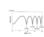
また、上記と同じ系で位相変調周波数を0.5[GHz]から20[GHz]まで変化させた場合における、受光器出力中の変調周波数成分の強度を数値計算により求めた結果を図5に示す。
図5においては、変調周波数fm=9.6、13.6、16.6、19.2[GHz]の各周波数成分において交流成分強度が極小値を取っていることが分かる。これらの4つの周波数は式(12)におけるk=1、2、3、4の場合に相当する。これらの値から被測定媒体13の|D|Lの値1360[ps/nm]が導出される。
Further, FIG. 5 shows the result of the numerical calculation of the intensity of the modulation frequency component in the output of the light receiver when the phase modulation frequency is changed from 0.5 [GHz] to 20 [GHz] in the same system as described above. Show.
In FIG. 5, it can be seen that the AC component intensity has a minimum value in each frequency component of the modulation frequency f m = 9.6, 13.6, 16.6, 19.2 [GHz]. These four frequencies correspond to the cases of k = 1, 2, 3, 4 in equation (12). From these values, the value 1360 [ps / nm] of | D | L of the measured
ここで、本実施例に係る波長分散方法の手順について説明する。
図6に示すように、はじめに、ステップS10において、光源10、位相変調器12、発振器11、分散媒体(被測定媒体)13、受光器14、スペクトラムアナライザ15を接続する。
Here, the procedure of the wavelength dispersion method according to the present embodiment will be described.
As shown in FIG. 6, first, in step S10, the
次に、ステップS11において、発振器11の周波数を掃引し、スペクトラムアナライザ15によって各変調周波数における交流成分強度を測定する。
次に、ステップS12において、交流成分強度が極小値を取る変調周波数fmを求める。
最後に、ステップS13において、式(12)より分散媒体(被測定媒体)13の総波長分散値|D|Lを求める。
Next, in step S11, the frequency of the
Next, in step S12, obtains the modulation frequency f m of the AC component intensity takes a minimum value.
Finally, in step S13, the total chromatic dispersion value | D | L of the dispersion medium (measuring medium) 13 is obtained from Expression (12).
本発明に係る波長分散測定装置及び波長分散測定方法の第2の実施例について説明する。
図7は本実施例に係る波長分散測定装置の一例を示す構成図、図8は受光器出力における交流成分強度と周波数の相関の計算結果を示すグラフ、図9は本実施例に係る波長分散方法の手順を説明するフローチャートである。
A second embodiment of the chromatic dispersion measuring apparatus and chromatic dispersion measuring method according to the present invention will be described.
FIG. 7 is a block diagram showing an example of a chromatic dispersion measuring apparatus according to the present embodiment, FIG. 8 is a graph showing a calculation result of the correlation between the AC component intensity and the frequency at the receiver output, and FIG. 9 is a chromatic dispersion according to the present embodiment. It is a flowchart explaining the procedure of a method.
図7に示すように、本実施例においては、図1に示した第1の実施例と異なり、周波数可変の発振器11の代わりに雑音発生器20が用いられる。この雑音発生器20から出力された広帯域の白色雑音信号を位相変調器12に入力し、光源10からの光に位相変調を施した後に分散媒体13に入射する。
As shown in FIG. 7, in this embodiment, unlike the first embodiment shown in FIG. 1, a
分散媒体13の出力を受光器14で電気信号に変換し、スペクトラムアナライザ15により白色雑音信号周波数範囲内の交流成分を観測する。分散媒体13中においては各周波数成分に対して位相変調−強度変調変換により強度変調成分が発生する。しかしながら、式(11)を満たす周波数については強度変調成分が0になるため、この周波数については交流成分強度が極小値を取る。この極小値を取る周波数から式(12)より分散媒体の波長分散を直接導出することが可能となる。
The output of the
第1の実施例と同じ波長分散Dが17[ps/(nm・km)]、長さLが80[km]のファイバを被測定媒体13として、本実施例における波長分散測定方法の動作確認を数値計算にて行った結果を図8に示す。
図8においては、変調周波数fm=9.6、13.6、16.6、19.2[GHz]の各周波数成分において交流成分強度が極小値を取っている。これらの4つの周波数は式(12)におけるk=1、2、3、4の場合に相当する。これらの値から被測定媒体13の|D|Lの値1360[ps/nm]が導出される。
Operation confirmation of the chromatic dispersion measuring method in this embodiment using a fiber having a chromatic dispersion D of 17 [ps / (nm · km)] and a length L of 80 [km] as in the first embodiment as a measured
In FIG. 8, the AC component intensity has a minimum value in each frequency component of the modulation frequency f m = 9.6, 13.6, 16.6, 19.2 [GHz]. These four frequencies correspond to the cases of k = 1, 2, 3, 4 in equation (12). From these values, the value 1360 [ps / nm] of | D | L of the measured
ここで、本実施例に係る波長分散方法の手順について説明する。
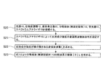
図9に示すように、はじめに、ステップS20において、光源10、位相変調器12、雑音発生器20、分散媒体(被測定媒体)13、受光器14、スペクトラムアナライザ15を接続する。
Here, the procedure of the wavelength dispersion method according to the present embodiment will be described.
As shown in FIG. 9, first, in step S20, the
次に、ステップS21において、スペクトラムアナライザ15によって交流成分強度の変調周波数依存性を測定する。
次に、ステップS22において、交流成分強度が極小値を取る変調周波数fmを求める。
最後に、ステップS23において、式(12)より分散媒体(被測定媒体)13の総波長分散値|D|Lを求める。
Next, in step S21, the
Next, in step S22, obtains the modulation frequency f m of the AC component intensity takes a minimum value.
Finally, in step S23, the total chromatic dispersion value | D | L of the dispersion medium (measuring medium) 13 is obtained from Expression (12).
本発明に係る波長分散測定装置及び波長分散測定方法の第3の実施例について説明する。
図10は本実施例に係る波長分散測定装置の一例を示す構成図、図11は本実施例に係る波長分散方法の手順を説明するフローチャートである。
図10に示すように、本実施例においては、図1に示した第1の実施例の構成に加えて、位相変調器12の後段に波長分散値が既知である分散媒体30が挿入されている。この分散媒体30が挿入された状態と、これを除いた状態の2回について分散測定を行うことにより、被測定媒体13の波長分散値と長さの積DLの値を、正負の符号も含めて導出することが可能となる。以下にその測定原理を示す。
A third embodiment of the wavelength dispersion measuring apparatus and wavelength dispersion measuring method according to the present invention will be described.
FIG. 10 is a configuration diagram illustrating an example of a chromatic dispersion measuring apparatus according to the present embodiment, and FIG. 11 is a flowchart illustrating a procedure of a chromatic dispersion method according to the present embodiment.
As shown in FIG. 10, in this embodiment, in addition to the configuration of the first embodiment shown in FIG. 1, a
波長分散値が既知である分散媒体30について、その波長分散値と長さをそれぞれD0、L0とおく。一方、被測定媒体13について、その波長分散値と長さをそれぞれD、Lとおく。これらの2つのファイバを接続して位相変調光を入射した場合について、強度変調周波数成分の強度が極小値を取る周波数の最小値(すなわち、式(11)において、k=1の場合の周波数)を、fm1とおく。この場合、以下の式(14)が成り立つ。
![]()
![]()
続いて、波長分散値が既知である分散媒体30を除去し、被測定媒体13のみに位相変調光を入射した場合について、強度変調周波数成分の強度が極小値を取る周波数の最小値(すなわち、式(11)において、k=1の場合の周波数)を、fm2とおく。この場合、以下の式(15)が成り立つ。
![]()
![]()
式(15)の両辺の2乗から式(14)の両辺の2乗を引くことにより、以下の式(16)が得られる。
ここで、本実施例に係る波長分散方法の手順について説明する。
図11に示すように、はじめに、ステップS30において、光源10、位相変調器12、発振器11、分散媒体(分散量既知)30、分散媒体(被測定媒体)13、受光器14、スペクトラムアナライザ15を接続する。
Here, the procedure of the wavelength dispersion method according to the present embodiment will be described.
As shown in FIG. 11, first, in step S30, the
次に、ステップS31において、発振器11の周波数を掃引し、スペクトラムアナライザ15によって各変調周波数における交流成分強度を測定する。
次に、ステップS32において、交流成分強度が極小値を取る変調周波数fm1を求める。
次に、ステップS33において、分散媒体(分散量既知)30を除去し、位相変調器12出力を分散媒体(被測定媒体)13に接続する。
Next, in step S31, the frequency of the
Next, in step S32, a modulation frequency f m1 at which the AC component intensity takes a minimum value is obtained.
Next, in step S33, the dispersion medium (dispersion amount known) 30 is removed, and the output of the
次に、ステップS34において、発振器11の周波数を掃引し、スペクトラムアナライザ15によって各変調周波数における交流成分強度を測定する。
次に、ステップS35において、交流成分強度が極小値を取る変調周波数fm2を求める。
最後に、ステップS36において、式(16)より分散媒体(被測定媒体)13の総波長分散値DLを求める。
Next, in step S34, the frequency of the
Next, in step S35, it obtains the modulation frequency f m2 where the AC component intensity takes a minimum value.
Finally, in step S36, the total chromatic dispersion value DL of the dispersion medium (measuring medium) 13 is obtained from equation (16).
本発明に係る波長分散測定装置及び波長分散測定方法の第4の実施例について説明する。
図12は本実施例に係る波長分散測定装置の一例を示す構成図、図13は本実施例に係る波長分散方法の手順を説明するフローチャートである。
図12に示すように、本実施例においては、使用される光源が波長可変光源31であることが特徴となる。これにより、波長可変光源31の出力可能な波長範囲内で分散測定を行うことが可能となる。
A fourth embodiment of the chromatic dispersion measuring apparatus and chromatic dispersion measuring method according to the present invention will be described.
FIG. 12 is a block diagram showing an example of a chromatic dispersion measuring apparatus according to this embodiment, and FIG. 13 is a flowchart for explaining the procedure of the chromatic dispersion method according to this embodiment.
As shown in FIG. 12, this embodiment is characterized in that the light source used is a wavelength variable
ここで、本実施例に係る波長分散方法の手順について説明する。
図13に示すように、はじめに、ステップS40において、波長可変光源31、位相変調器12、雑音発生器20、分散媒体(被測定媒体)13、受光器14、スペクトラムアナライザ15を接続する。
Here, the procedure of the wavelength dispersion method according to the present embodiment will be described.
As shown in FIG. 13, first, in step S40, the wavelength tunable
次に、ステップS41において、スペクトラムアナライザ15によって交流成分強度の変調周波数依存性を測定する。
次に、ステップS42において、交流成分強度が極小値を取る変調周波数fmを求める。
次に、ステップS43において、式(12)より分散媒体(被測定媒体)13の総波長分散値|D|Lを求める。
Next, in step S41, the
Next, in step S42, obtains the modulation frequency f m of the AC component intensity takes a minimum value.
Next, in step S43, the total chromatic dispersion value | D | L of the dispersion medium (measuring medium) 13 is obtained from Expression (12).
次に、ステップS44において、波長可変光源の設定波長を変化させる。波長可変光源の設定波長を変化後、再度ステップS41からステップS43を実行する。そして、波長可変光源31の出力可能な波長範囲内、又は波長分散測定を必要とする範囲内で設定波長を変化させ終えた後、ステップS45へ移行する。
最後に、ステップS45において、分散媒体(被測定媒体)13の総波長分散値|D|Lを求める。
Next, in step S44, the set wavelength of the wavelength tunable light source is changed. After changing the set wavelength of the wavelength tunable light source, steps S41 to S43 are executed again. Then, after changing the set wavelength within the wavelength range that can be output from the wavelength tunable
Finally, in step S45, the total chromatic dispersion value | D | L of the dispersion medium (measuring medium) 13 is obtained.
〔他の実施例〕
以上、本発明に係る波長分散測定装置及び波長分散測定方法の好適な実施例を例示して説明したが、本発明の実施形態は上述した実施例に限定されるものではなく、本発明の範囲内において、その構成部材等の置換、変更、追加、個数の増減、形状の設計変更、設定パラメータの変更等を行うことは、全て本発明の範囲に含まれるものである。
[Other Examples]
The preferred embodiments of the chromatic dispersion measuring apparatus and the chromatic dispersion measuring method according to the present invention have been illustrated and described above, but the embodiments of the present invention are not limited to the above-described embodiments, and the scope of the present invention. It is within the scope of the present invention to replace, change, add, increase / decrease the number of components, change the shape design, change the setting parameters, and the like.
上記非特許文献5及び上記非特許文献6の波長分散測定装置においては、強度変調器のαパラメータの値の誤差が波長分散の測定誤差につながる。また、上記特許文献1の波長分散測定装置においては、波長分散を導出するために、位相変調指数が既知の測定系を用意するか、位相変調指数を別途測定する必要がある。さらに、上記特許文献1の波長分散測定装置においては、受光器出力における直流成分と交流成分の強度比の測定誤差が波長分散の測定誤差につながる。
In the chromatic dispersion measuring devices of
これに対し、本発明に係る波長分散測定装置及び波長分散測定方法においては、測定誤差を増大させる要因である位相変調器12のαパラメータ、変調指数、測定系の損失の各々の影響が含有されず、交流信号の周波数の値のみから高精度な波長分散値を導出することが可能である。
On the other hand, the chromatic dispersion measuring device and the chromatic dispersion measuring method according to the present invention include the effects of the α parameter of the
本発明は、光ファイバや光部品の基本特性の一つである波長分散値を測定する波長分散測定装置に利用することが可能である。 The present invention can be used in a chromatic dispersion measuring apparatus that measures a chromatic dispersion value, which is one of the basic characteristics of optical fibers and optical components.
10 光源
11 位相変調器
12 発振器(周波数可変)
13 分散媒体(被測定媒体)
14 受光器
15 スペクトラムアナライザ
20 雑音発生器
30 波長分散量が既知である分散媒体
31 波長可変光源
40 強度変調器
41 ネットワークアナライザ
50 発振器(周波数固定)
51 分波器
52 光スペクトラムアナライザ
53 交流電圧計
54 直流電圧計
55 バンドパスフィルタ
56 光増幅器
57 可変光減衰器
58 比較器
10
13 Dispersion medium (measuring medium)
14
51
Claims (8)
連続光を発生させる光源と、
周波数掃引可能な正弦波信号を発生する電気信号発生器と、
前記電気信号発生器から出力される正弦波信号によって駆動され、前記光源の出力光に対して位相変調を行う位相変調器と、
前記位相変調器から出力される出力光を、前記被測定媒体に入射した際の出力光を電気信号に変換する受光器と、
前記受光器から出力される電気信号の交流成分の強度を観測する交流成分観測手段と
を具備し、
前記交流成分観測手段により交流成分が極小値を取る周波数を求め、この周波数から被測定媒体の波長分散値を求める
ことを特徴とする波長分散測定装置。 In the chromatic dispersion measuring device for obtaining the chromatic dispersion value of the measured medium,
A light source that generates continuous light;
An electrical signal generator for generating a frequency sweepable sinusoidal signal;
A phase modulator driven by a sine wave signal output from the electrical signal generator and performing phase modulation on the output light of the light source;
A light receiver that converts the output light output from the phase modulator into an electrical signal when the light is incident on the measured medium; and
AC component observation means for observing the intensity of the AC component of the electrical signal output from the light receiver,
A chromatic dispersion measuring apparatus characterized in that a frequency at which an AC component takes a minimum value is obtained by the AC component observation means, and a chromatic dispersion value of a medium to be measured is obtained from this frequency.
連続光を発生させる光源と、
広帯域な電気雑音成分を発生する雑音発生器と、
前記雑音発生器から出力される電気雑音成分によって駆動され、前記光源の出力光に対して位相変調を行う位相変調器と、
前記位相変調器から出力される出力光を前記被測定媒体に入射した際の出力光を電気信号に変換する受光器と、
前記受光器から出力される電気信号の交流成分の強度を観測する交流成分観測手段と
を具備し、
前記交流成分観測手段により交流成分が極小値を取る周波数を求め、この周波数から被測定媒体の波長分散値を求める
ことを特徴とする波長分散測定装置。 In the chromatic dispersion measuring device for obtaining the chromatic dispersion value of the measured medium,
A light source that generates continuous light;
A noise generator that generates a wide-band electrical noise component;
A phase modulator driven by an electrical noise component output from the noise generator and performing phase modulation on the output light of the light source;
A light receiver for converting the output light output from the phase modulator into an electric signal when the output light is incident on the measured medium;
AC component observation means for observing the intensity of the AC component of the electrical signal output from the light receiver,
A chromatic dispersion measuring apparatus characterized in that a frequency at which an AC component takes a minimum value is obtained by the AC component observation means, and a chromatic dispersion value of a medium to be measured is obtained from this frequency.
前記位相変調器から出力される出力光を前記波長分散値が既知である分散媒体を通した後に前記被測定媒体に入射した場合と、前記位相変調器から出力される出力光を前記被測定媒体に直接入射した場合との2通りについて前記交流成分観測手段により交流成分が極小値を取る周波数を求め、これらの周波数から前記被測定媒体の波長分散値を符号も含めて求める
ことを特徴とする請求項1又は請求項2に記載の波長分散測定装置。 A dispersion medium having a known chromatic dispersion value is provided after the phase modulator,
When the output light output from the phase modulator passes through the dispersion medium whose chromatic dispersion value is known and then enters the measured medium, and the output light output from the phase modulator is the measured medium The frequency at which the AC component takes a minimum value is obtained by the AC component observation means for the two cases of direct incidence on the light, and the chromatic dispersion value of the measured medium including the sign is obtained from these frequencies. The chromatic dispersion measuring apparatus according to claim 1 or 2.
前記被測定媒体の波長分散値の波長依存性を測定する
ことを特徴とする請求項1から請求項3のいずれか1項に記載の波長分散測定装置。 The light source is a wavelength variable light source in which the wavelength of the continuous light is variable;
The wavelength dispersion measuring apparatus according to any one of claims 1 to 3, wherein wavelength dependency of a wavelength dispersion value of the medium to be measured is measured.
連続光を発生する工程と、
周波数掃引可能な正弦波信号を発生する工程と、
前記正弦波信号を用いて前記連続光に対して位相変調を行う工程と、
位相変調された前記連続光を前記被測定媒体に入射した際の出力光を電気信号に変換する工程と、
前記電気信号の交流成分の強度を観測する工程と、
前記交流成分が極小値を取る周波数を求め、この周波数から被測定媒体の波長分散値を求める工程と
を具備する
ことを特徴とする波長分散測定方法。 In the chromatic dispersion measuring method for obtaining the chromatic dispersion value of the measured medium,
A process of generating continuous light;
Generating a frequency sweepable sinusoidal signal;
Performing phase modulation on the continuous light using the sine wave signal;
Converting the output light when the phase-modulated continuous light is incident on the measured medium into an electrical signal;
Observing the intensity of the alternating current component of the electrical signal;
And a step of obtaining a frequency at which the AC component takes a minimum value, and obtaining a chromatic dispersion value of the medium to be measured from the frequency.
連続光を発生させる工程と、
広帯域な電気雑音成分を発生させる工程と、
前記電気雑音成分を用いて前記連続光に対して位相変調を行う工程と、
位相変調された前記連続光を前記被測定媒体に入射した際の出力光を電気信号に変換する工程と、
前記電気信号の交流成分の強度を観測する工程と、
前記交流成分が極小値を取る周波数を求め、この周波数から被測定媒体の波長分散値を求める工程と
を具備する
ことを特徴とする波長分散測定方法。 In the chromatic dispersion measuring method for obtaining the chromatic dispersion value of the measured medium,
A step of generating continuous light;
Generating a wide-band electrical noise component;
Performing phase modulation on the continuous light using the electrical noise component;
Converting the output light when the phase-modulated continuous light is incident on the measured medium into an electrical signal;
Observing the intensity of the alternating current component of the electrical signal;
And a step of obtaining a frequency at which the AC component takes a minimum value, and obtaining a chromatic dispersion value of the medium to be measured from the frequency.
位相変調された前記連続光を前記分散媒体を通した後に前記被測定媒体に入射した場合と、位相変調された前記連続光を前記被測定媒体に直接入射した場合との2通りについて交流成分が極小値を取る周波数を求め、これらの周波数から前記被測定媒体の波長分散値を符号も含めて求める工程と
を具備する
ことを特徴とする請求項5又は請求項6に記載の波長分散測定方法。 Passing the phase-modulated continuous light through a dispersion medium having a known chromatic dispersion value;
The AC component is divided into two types: a case where the phase-modulated continuous light passes through the dispersion medium and then enters the medium to be measured, and a case where the phase-modulated continuous light directly enters the medium to be measured. 7. A method for measuring chromatic dispersion according to claim 5 or 6, further comprising: obtaining a frequency that takes a minimum value, and obtaining a chromatic dispersion value of the measured medium including a sign from these frequencies. .
前記被測定媒体の波長分散値の波長依存性を測定する
ことを特徴とする請求項5から請求項7のいずれか1項に記載の波長分散測定方法。 The continuous light has a variable wavelength,
The chromatic dispersion measuring method according to claim 5, wherein wavelength dependency of a chromatic dispersion value of the medium to be measured is measured.
Priority Applications (1)
| Application Number | Priority Date | Filing Date | Title |
|---|---|---|---|
| JP2008186856A JP5179277B2 (en) | 2008-07-18 | 2008-07-18 | Chromatic dispersion measuring apparatus and chromatic dispersion measuring method |
Applications Claiming Priority (1)
| Application Number | Priority Date | Filing Date | Title |
|---|---|---|---|
| JP2008186856A JP5179277B2 (en) | 2008-07-18 | 2008-07-18 | Chromatic dispersion measuring apparatus and chromatic dispersion measuring method |
Publications (2)
| Publication Number | Publication Date |
|---|---|
| JP2010025725A true JP2010025725A (en) | 2010-02-04 |
| JP5179277B2 JP5179277B2 (en) | 2013-04-10 |
Family
ID=41731704
Family Applications (1)
| Application Number | Title | Priority Date | Filing Date |
|---|---|---|---|
| JP2008186856A Expired - Fee Related JP5179277B2 (en) | 2008-07-18 | 2008-07-18 | Chromatic dispersion measuring apparatus and chromatic dispersion measuring method |
Country Status (1)
| Country | Link |
|---|---|
| JP (1) | JP5179277B2 (en) |
Citations (2)
| Publication number | Priority date | Publication date | Assignee | Title |
|---|---|---|---|---|
| JPH07113722A (en) * | 1993-10-19 | 1995-05-02 | Nippon Telegr & Teleph Corp <Ntt> | Wavelength dispersion measuring device for optical fiber |
| JPH1062570A (en) * | 1996-06-12 | 1998-03-06 | Oyo Koden Kenkiyuushitsu:Kk | Method and apparatus for measuring time lag |
-
2008
- 2008-07-18 JP JP2008186856A patent/JP5179277B2/en not_active Expired - Fee Related
Patent Citations (2)
| Publication number | Priority date | Publication date | Assignee | Title |
|---|---|---|---|---|
| JPH07113722A (en) * | 1993-10-19 | 1995-05-02 | Nippon Telegr & Teleph Corp <Ntt> | Wavelength dispersion measuring device for optical fiber |
| JPH1062570A (en) * | 1996-06-12 | 1998-03-06 | Oyo Koden Kenkiyuushitsu:Kk | Method and apparatus for measuring time lag |
Also Published As
| Publication number | Publication date |
|---|---|
| JP5179277B2 (en) | 2013-04-10 |
Similar Documents
| Publication | Publication Date | Title |
|---|---|---|
| Li et al. | Few-mode fiber based optical sensors | |
| Zou et al. | Microwave frequency measurement based on optical power monitoring using a complementary optical filter pair | |
| Chen et al. | A distributed fiber vibration sensor utilizing dispersion induced walk-off effect in a unidirectional Mach-Zehnder interferometer | |
| He et al. | Multiple vibrations measurement using phase-sensitive OTDR merged with Mach-Zehnder interferometer based on frequency division multiplexing | |
| JP2000180265A (en) | Brillouin gain spectrum measuring method and device | |
| CN108917804A (en) | Quick long-distance distributed Brillouin light fiber sensing equipment based on chirp chain | |
| Baker et al. | Chromatic-dispersion measurement by modulation phase-shift method using a Kerr phase-interrogator | |
| JP4586033B2 (en) | Optical heterodyne interferometer and optical path length difference measuring method thereof | |
| Wen et al. | Accuracy-enhanced wideband optical vector network analyzer based on double-sideband modulation | |
| Liang et al. | Precision dynamic sensing with ultra-weak fiber Bragg grating arrays by wavelength to frequency transform | |
| Ahn et al. | Optical frequency-domain chromatic dispersion measurement method for higher-order modes in an optical fiber | |
| US11698277B2 (en) | Method and system for determining grating perturbation by modulated light | |
| Sakhbiev et al. | Optical vector network analyzer based on unbalanced amplitude-phase modulation | |
| EP2562527B1 (en) | Method, apparatus, and program for measuring wavelength dispersion of optical waveguide | |
| Zou et al. | Self-calibrated electrical measurement of magnitude response of optical filters based on dual-frequency-shifted heterodyne | |
| Pan et al. | Optical vector network analyzer based on optical single-sideband modulation | |
| Costa et al. | Fast and direct measurement of the linear birefringence profile in standard single-mode optical fibers | |
| JP2011102795A (en) | Wavelength dispersion measuring device and method using the same | |
| JP5179277B2 (en) | Chromatic dispersion measuring apparatus and chromatic dispersion measuring method | |
| JP2014149190A (en) | Measuring device, measuring method, light source device, and article manufacturing method | |
| JP6281864B2 (en) | Optical fiber characteristic measuring apparatus and optical fiber characteristic measuring method | |
| Takada et al. | Coherent frequency-modulated continuous wave reflectometry for measuring stationary Brillouin grating induced under uniform pumping by counterpropagating nonmodulated light waves | |
| Fu et al. | Simple and precise characterization of differential modal group delay arising in few-mode fiber | |
| JP2018021890A (en) | Device for measuring difference in inter-spatial channel propagation delay time and method for measuring difference in inter-spatial channel propagation delay time | |
| Jeon et al. | Optical fiber chromatic dispersion measurement using bidirectional modulation of an optical intensity modulator |
Legal Events
| Date | Code | Title | Description |
|---|---|---|---|
| A621 | Written request for application examination |
Free format text: JAPANESE INTERMEDIATE CODE: A621 Effective date: 20100726 |
|
| A131 | Notification of reasons for refusal |
Free format text: JAPANESE INTERMEDIATE CODE: A131 Effective date: 20120508 |
|
| A521 | Written amendment |
Free format text: JAPANESE INTERMEDIATE CODE: A523 Effective date: 20120629 |
|
| TRDD | Decision of grant or rejection written | ||
| A01 | Written decision to grant a patent or to grant a registration (utility model) |
Free format text: JAPANESE INTERMEDIATE CODE: A01 Effective date: 20130108 |
|
| A61 | First payment of annual fees (during grant procedure) |
Free format text: JAPANESE INTERMEDIATE CODE: A61 Effective date: 20130109 |
|
| R150 | Certificate of patent or registration of utility model |
Ref document number: 5179277 Country of ref document: JP Free format text: JAPANESE INTERMEDIATE CODE: R150 |
|
| S531 | Written request for registration of change of domicile |
Free format text: JAPANESE INTERMEDIATE CODE: R313531 |
|
| R350 | Written notification of registration of transfer |
Free format text: JAPANESE INTERMEDIATE CODE: R350 |
|
| LAPS | Cancellation because of no payment of annual fees |