JP2010025416A - Wire take-up/supply device, and movable panel lifting and lowering device of air conditioning indoor unit comprising the same - Google Patents
Wire take-up/supply device, and movable panel lifting and lowering device of air conditioning indoor unit comprising the same Download PDFInfo
- Publication number
- JP2010025416A JP2010025416A JP2008186411A JP2008186411A JP2010025416A JP 2010025416 A JP2010025416 A JP 2010025416A JP 2008186411 A JP2008186411 A JP 2008186411A JP 2008186411 A JP2008186411 A JP 2008186411A JP 2010025416 A JP2010025416 A JP 2010025416A
- Authority
- JP
- Japan
- Prior art keywords
- wire
- winding
- movable panel
- outer peripheral
- indoor unit
- Prior art date
- Legal status (The legal status is an assumption and is not a legal conclusion. Google has not performed a legal analysis and makes no representation as to the accuracy of the status listed.)
- Granted
Links
Images


Landscapes
- Air Filters, Heat-Exchange Apparatuses, And Housings Of Air-Conditioning Units (AREA)
Abstract
Description
本発明は、ワイヤーを巻付部材に巻き付かせるワイヤー巻き取り・繰り出し装置、およびそのワイヤー巻き取り・繰り出し装置を備えた空調室内機の可動パネル昇降装置関する。 The present invention relates to a wire winding / feeding device for winding a wire around a winding member, and a movable panel lifting / lowering device for an air conditioning indoor unit including the wire winding / feeding device.
従来、天井設置型の空調室内機として、化粧パネルの開口を昇降可能な可動パネルで閉じる空調室内機が広く知られている(例えば、特許文献1参照)。その空調室内機では、可動パネルは複数のワイヤーで吊られており、可動パネル昇降装置がそのワイヤーを繰り出すことによって可動パネルが降下し、ワイヤーを巻き取ることによって可動パネルが上昇する。 2. Description of the Related Art Conventionally, an air conditioning indoor unit that closes an opening of a decorative panel with a movable panel that can be moved up and down is widely known as a ceiling-mounted air conditioning indoor unit (for example, see Patent Document 1). In the air conditioner indoor unit, the movable panel is suspended by a plurality of wires, and the movable panel elevating device lowers the movable panel by drawing out the wire, and winds the wire to raise the movable panel.
しかしながら、上記空調室内機に使用されている可動パネル昇降装置は、ワイヤーを糸巻形状の巻付部材に巻き付かせる構成であり、ワイヤーの上にワイヤーが重なるので、ワイヤーが巻付部材から外れて絡み合う可能性が高い。
本発明の課題は、巻付部材からのワイヤーの外れ、或は、巻付部材とワイヤーとが絡まることを防止したワイヤー巻き取り・繰り出し装置、及びそのワイヤー巻き取り・繰り出し装置を備えた空調室内機の可動パネル昇降装置を提供することにある。 An object of the present invention is to provide a wire take-up / feeding device that prevents the wire from coming off from the winding member, or the winding member and the wire are entangled, and an air-conditioning room equipped with the wire take-up / feeding device. It is in providing the movable panel raising / lowering apparatus of a machine.
第1発明に係るワイヤー巻き取り・繰り出し装置は、対象物に接続されたワイヤーを巻き取り、又は繰り出すためのワイヤー巻き取り・繰り出し装置であって、モータと、巻付部材と、付勢部材とを備えている。巻付部材は、モータによって回転駆動され外周面にワイヤーが巻き付く。付勢部材は、巻き付いた状態のワイヤーに巻付部材の外周側から接触してワイヤーを巻付部材の外周面に押付ける。 The wire winding / unwinding device according to the first invention is a wire winding / unwinding device for winding or unwinding a wire connected to an object, and includes a motor, a winding member, and an urging member. It has. The winding member is rotationally driven by a motor, and a wire is wound around the outer peripheral surface. The biasing member contacts the wound wire from the outer peripheral side of the winding member and presses the wire against the outer peripheral surface of the winding member.
このワイヤー巻き取り・繰り出し装置では、ワイヤーを巻き取るとき、付勢部材によってワイヤーが山状に巻き付くことが抑制されるので、ワイヤーが巻付部材を越えて外れることが防止される。また、ワイヤーが繰り出されるとき、ワイヤーに作用する負荷がなくなり張力がなくなった場合でも、巻付部材に巻きついていたワイヤーが緩んで解けることが防止されるので、巻付部材とワイヤーとが絡まることが防止される。 In this wire winding / feeding device, when the wire is wound, the urging member suppresses the wire from being wound in a mountain shape, so that the wire is prevented from coming off beyond the winding member. Also, when the wire is unwound, even if there is no load acting on the wire and tension is lost, the wire wound around the winding member is prevented from loosening and unraveling, so that the winding member and the wire become entangled Is prevented.
第2発明に係るワイヤー巻き取り・繰り出し装置は、第1発明に係るワイヤー巻き取り・繰り出し装置であって、付勢部材が、ワイヤーの外周面からの高さ変化に対して弾性変形によって追従する。 The wire winding / feeding device according to the second invention is the wire winding / feeding device according to the first invention, wherein the biasing member follows the height change from the outer peripheral surface of the wire by elastic deformation. .
このワイヤー巻き取り・繰り出し装置では、巻かれたワイヤーの高さが変化したときでも、ワイヤーと付勢部材との隙間が瞬時に詰められるので、ワイヤーが緩んで解けることが防止され、巻付部材からのワイヤーの外れ、或は、巻付部材とワイヤーとが絡まることが防止される。 In this wire winding / feeding device, even when the height of the wound wire changes, the gap between the wire and the biasing member is instantly filled, so that the wire is prevented from loosening and unwinding, and the winding member It is possible to prevent the wire from coming off, or the winding member and the wire from being tangled.
第3発明に係るワイヤー巻き取り・繰り出し装置は、第1発明に係るワイヤー巻き取り・繰り出し装置であって、付勢部材が樹脂製である。このワイヤー巻き取り・繰り出し装置では、ワイヤーと付勢部材との摩擦が小さく、ワイヤーの傷つきが抑制される。また、ワイヤーと付勢部材との摩擦音も抑制される。 The wire winding / feeding device according to the third invention is the wire winding / feeding device according to the first invention, and the urging member is made of resin. In this wire winding / feeding device, the friction between the wire and the urging member is small, and damage to the wire is suppressed. Further, frictional noise between the wire and the biasing member is also suppressed.
第4発明に係るワイヤー巻き取り・繰り出し装置は、第1発明に係るワイヤー巻き取り・繰り出し装置であって、付勢部材が金属製である。このワイヤー巻き取り・繰り出し装置では、付勢部材の耐久性が向上する。 The wire winding / unwinding device according to a fourth aspect of the present invention is the wire winding / unwinding device according to the first aspect, wherein the urging member is made of metal. In this wire winding / unwinding device, the durability of the urging member is improved.
第5発明に係るワイヤー巻き取り・繰り出し装置は、第1発明に係るワイヤー巻き取り・繰り出し装置であって、付勢部材の縦断面が円弧形状である。このワイヤー巻き取り・繰り出し装置では、ワイヤーの巻き形状に沿いやすく、省スペースである。 A wire winding / unwinding device according to a fifth aspect of the present invention is the wire winding / unwinding device according to the first aspect of the present invention, wherein the urging member has a circular cross section. This wire winding / feeding device is easy to follow the winding shape of the wire and saves space.
第6発明に係るワイヤー巻き取り・繰り出し装置は、第5発明に係るワイヤー巻き取り・繰り出し装置であって、付勢部材には、円弧形状の中心に対して中心角180°以上の円弧が形成されている。このワイヤー巻き取り・繰り出し装置では、付勢部材単体で巻付部材及びワイヤーに装着可能であり、外れて落下することが防止される。 A wire winding / unwinding device according to a sixth aspect of the present invention is the wire winding / unwinding device according to the fifth aspect of the present invention, wherein the urging member has an arc having a central angle of 180 ° or more with respect to the center of the arc shape Has been. In this wire winding / feeding device, the urging member alone can be attached to the winding member and the wire, and it is prevented from coming off and falling.
第7発明に係るワイヤー巻き取り・繰り出し装置は、第5発明に係るワイヤー巻き取り・繰り出し装置であって、付勢部材には、ワイヤーの巻き取り又は繰り出しの中心軸方向の振れを制限するする規制部材が設けられている。このワイヤー巻き取り・繰り出し装置では、巻取部材の回転時に付勢部材が回転軸方向に振れないので、ワイヤーが巻取部材に安定して巻き付く。 A wire winding / feeding device according to a seventh aspect of the present invention is the wire winding / feeding device according to the fifth aspect of the present invention, wherein the biasing member restricts the deflection of the winding or feeding of the wire in the central axis direction. A regulating member is provided. In this wire winding / feeding device, the urging member cannot swing in the direction of the rotation axis when the winding member rotates, so that the wire is stably wound around the winding member.
第8発明に係る空調室内機の可動パネル昇降装置は、空気吸込口の近傍にワイヤーを介して吊られる可動パネルを、ワイヤーの動作によって昇降および/または空気吸込口の開閉を行わせる空調室内機の可動パネル昇降装置であって、ワイヤーを動作させる第1発明から第7発明のいずれか1つに係るワイヤー巻き取り・繰り出し装置を備えている。 The movable panel lifting / lowering device for an air conditioning indoor unit according to the eighth aspect of the invention is an air conditioning indoor unit that causes a movable panel suspended through a wire in the vicinity of an air suction port to lift and / or open / close the air suction port by operation of the wire. The movable panel lifting / lowering device includes a wire winding / feeding device according to any one of the first to seventh inventions for operating the wire.
この可動パネル昇降装置では、可動パネルを降下させるとき、ワイヤーに作用する負荷がなくなり張力がなくなった場合でも、巻付部材に巻きついていたワイヤーが緩んで解けることが防止されるので、巻付部材とワイヤーとが絡まることが防止される。また、可動パネルを上昇させるとき、付勢部材によってワイヤーが山状に巻き付くことが抑制されるので、ワイヤーが巻付部材を越えて外れることが防止される。 In this movable panel lifting and lowering device, when the movable panel is lowered, even if there is no load acting on the wire and the tension is lost, the wire wound around the winding member is prevented from being loosened and unwound. And the wire are prevented from getting tangled. Further, when the movable panel is raised, the urging member suppresses the wire from being wound in a mountain shape, so that the wire is prevented from coming off beyond the winding member.
第1発明に係るワイヤー巻き取り・繰り出し装置では、ワイヤーが巻付部材を越えて外れること、或は、巻付部材とワイヤーとが絡まることが防止される。 In the wire winding / feeding device according to the first aspect of the invention, the wire is prevented from coming off beyond the winding member, or the winding member and the wire are prevented from being entangled.
第2発明に係るワイヤー巻き取り・繰り出し装置では、巻かれたワイヤーの高さが変化したときでも、ワイヤーと付勢部材との隙間が瞬時に詰められるので、巻付部材からのワイヤーの外れ、或は、巻付部材とワイヤーとが絡まることが防止される。 In the wire winding and unwinding device according to the second invention, even when the height of the wound wire is changed, the gap between the wire and the biasing member is instantaneously packed, so that the wire comes off from the winding member, Or it is prevented that a winding member and a wire get entangled.
第3発明に係るワイヤー巻き取り・繰り出し装置では、ワイヤーと付勢部材との摩擦が小さく、ワイヤーの傷つきが抑制される。また、ワイヤーと付勢部材との摩擦音も抑制される。 In the wire winding / feeding device according to the third aspect of the present invention, the friction between the wire and the biasing member is small, and damage to the wire is suppressed. Further, frictional noise between the wire and the biasing member is also suppressed.
第4発明に係るワイヤー巻き取り・繰り出し装置では、付勢部材の耐久性が向上する。 In the wire winding / unwinding device according to the fourth aspect of the invention, the durability of the urging member is improved.
第5発明に係るワイヤー巻き取り・繰り出し装置では、付勢部材がワイヤーの巻き形状に沿いやすく、省スペースである。 In the wire winding / unwinding device according to the fifth aspect of the invention, the urging member can easily follow the winding shape of the wire, saving space.
第6発明に係るワイヤー巻き取り・繰り出し装置では、付勢部材単体で巻付部材及びワイヤーに装着可能であり、外れて落下することが防止される。 In the wire winding / feeding device according to the sixth aspect of the invention, the urging member alone can be attached to the winding member and the wire, and is prevented from coming off and falling.
第7発明に係るワイヤー巻き取り・繰り出し装置では、巻取部材の回転時に付勢部材が回転軸方向に振れないので、ワイヤーが巻取部材に安定して巻き付く。 In the wire winding and unwinding device according to the seventh aspect of the invention, the urging member cannot swing in the direction of the rotation axis when the winding member rotates, so that the wire is stably wound around the winding member.
第8発明に係る空調室内機の可動パネル昇降装置では、可動パネルを降下させるとき、巻付部材とワイヤーとが絡まることが防止される。また、可動パネルを上昇させるとき、ワイヤーが巻付部材を越えて外れることが防止される。 In the movable panel lifting / lowering apparatus for an air conditioning indoor unit according to the eighth aspect of the present invention, when the movable panel is lowered, the winding member and the wire are prevented from being tangled. Further, when the movable panel is raised, the wire is prevented from coming off beyond the winding member.
以下図面を参照しながら、本発明の実施形態について説明する。なお、以下の実施形態は、本発明の具体例であって、本発明の技術的範囲を限定するものではない。 Embodiments of the present invention will be described below with reference to the drawings. The following embodiments are specific examples of the present invention and do not limit the technical scope of the present invention.
<空調室内機2の構成>
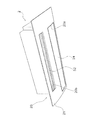
図1は本発明の一実施形態に係る昇降装置を備えた空調室内機の外観斜視図である。図1において、空調室内機2は、下面に吸込口20a及び吹出口20bを有する本体20と、吸込口20aを開閉する可動パネル24及び吹出口20bを開閉する第1風向調節羽根52とを備えている。吸込口20aと吹出口20bとは一定距離を隔てて隣接しており、吹出口20bから吹き出された空気が吸込口20aに吸い込まれる現象、いわゆるショートサーキットが発生しないようになっている。本体20の下面は、化粧パネル21によって覆われており、実際に天井面に露出するのは化粧パネル21であって、吸込口20a及び吹出口20bの輪郭は化粧パネル21によって形成されている。ここでは、化粧パネル21も本体20に含まれている。
<Configuration of air conditioning
FIG. 1 is an external perspective view of an air conditioning indoor unit equipped with a lifting device according to an embodiment of the present invention. In FIG. 1, the air conditioning
図2(a)は、空調室内機の運転停止時の側面図であり、(b)は、その空調室内機の運転時の側面図であり、(c)は、その空調室内機のメンテナンス時の側面図である。図2(a),(b),(c)において、空調室内機2が停止しているとき、可動パネル24は化粧パネル21と見かけ上一体化している。図2(b)において、空調室内機2が稼動するとき、可動パネル24は吸込口20aを開き、第1風向調節羽根52は吹出口20bを開く。可動パネル24の一端は蝶番によって本体20に支持されており、可動パネル24は回動して吸込口20aを開ける。
FIG. 2A is a side view when the operation of the air-conditioning indoor unit is stopped, FIG. 2B is a side view when the air-conditioning indoor unit is operated, and FIG. FIG. 2A, 2B, and 2C, the
また、図2(c)において、可動パネル24は、本体20側から延びるワイヤー71に吊られた状態で使用者の手が届くメンテナンス位置まで降下することができる。但し、可動パネル24は、一端が蝶番によって本体20に支持されている状態ではメンテナンス位置まで降下することができないので、一旦、吸込口20aを閉じて、本体20による支持が解除されたのちにメンテナンス位置まで降下する。
Moreover, in FIG.2 (c), the
図3は、空調室内機の断面図である。図3において、空調室内機2は、フィルタ9、フィルタ清掃機構10、室内熱交換器12、室内ファン13、ドレンパン14及び吹出口モジュール50をさらに備えている。空調室内機2の運転時、吸込口20a及び吹出口20bが開き、室内ファン13が回転し、空気が吸込口20aから吸い込まれる。
FIG. 3 is a cross-sectional view of the air conditioning indoor unit. In FIG. 3, the air conditioning
(室内熱交換器12)
室内熱交換器12は、2つの熱交換器が異なる傾斜姿勢で隣接した形状をしており、説明の便宜上、上側の熱交換器を上部熱交換器12a、下側の熱交換器を下部熱交換器12bと呼ぶ。
(Indoor heat exchanger 12)
The
上部熱交換器12aの上端は本体20の内側上部に位置し、上端から下端に向って傾斜する角度は、水平線に対して45°以上65°以下(好ましくは55°)に設定されており、結露水が確実に上部熱交換器12aを伝わってドレンパン14に向う。このため、ドレンパン14は、上部熱交換器12aの下方全域に配置される必要が無く、上部熱交換器12aの下端近傍の下方にだけ配置されている。
The upper end of the
下部熱交換器12bの上端は、上部熱交換器12aの下端に近接して配置されており、上端から下端に向って傾斜する角度は、水平線に対して45°未満である。このため、結露水が直接落下する可能性があるので、ドレンパン14は、下部熱交換器12bの下方全域に配置されている。
The upper end of the
(室内ファン13)
室内ファン13は、クロスフローファンであり、幅寸法が直径よりも長く、回転軸と垂直な方向から空気を吸い込むので、単一の吸込口20aから空気を吸い込んで、単一の吹出口20bへ吹き出すことができる。吸い込まれた空気は、フィルタ9及び室内熱交換器12を通過して室内ファン13に入る。
(Indoor fan 13)
The
室内ファン13から吹き出された空気は、吹出口モジュール50を通過して吹出口20bから吹き出される。吹出口20bには、吹出口モジュール50の構成部品である第1風向調節羽根52が配置されており、第1風向調節羽根52は、モータによって傾斜角度の調節が可能であり、運転停止時は、第1風向調節羽根52が吹出口20bを閉じる。室内ファン13とドレンパン14との間で且つ吹出流路41a側には、舌部15が設けられており、この舌部15が吹出空気の漏れを防止して、性能を向上させている。
The air blown out from the
<フィルタ清掃機構10>
図3に示すように、空調室内機2は、可動パネル24の上方に、フィルタ清掃機構10を備えている。以下、フィルタ清掃機構10の構成部材について説明する。
<
As shown in FIG. 3, the air conditioning
(フィルタ9)
フィルタ9は、室内熱交換器12の前面側に配置され、室内から取り込まれた空気から塵埃を除去する。これにより、フィルタ9は、空気中に浮遊する塵埃が室内熱交換器12の表面を汚染することを防止している。フィルタ9の縁部には、ピニオン歯車102aと噛み合うラック101が形成されている。
(Filter 9)
The
(ローラー102)
ローラー102は、ピニオン歯車102aを有している。ピニオン歯車102aは、フィルタ9のラック101と噛み合っており、回転することによってフィルタ9を水平に移動させる。
(Roller 102)
The
(位置検知スイッチ107)
フィルタ9の停止位置は、位置検知スイッチ107によって検知される。位置検知スイッチ107は、前方収納部105の終端近傍、及び後方収納部106の終端近傍に配置されている。位置検知スイッチ107の外側には、レバーが蝶番によって装着されており、外力が加わると回動して位置検知スイッチ107のボタンを押す。
(Position detection switch 107)
The stop position of the
(ブラシ108とダストボックス109)
ブラシ108は、フィルタ9を挟んでローラー102と反対側に位置しフィルタ9に接触している。ダストボックス109は、上部の吹出口20b寄りに、塵埃取り込み口を有しており、塵埃取り込み口の長手方向の両端で、軸受を介してブラシ108の回転軸を支持する。さらに、塵埃取り込み口には、ブラシ108がフィルタ9から掻き取った塵埃をブラシ108からふるい落とす櫛部109cが取り付けられている。
(Brush 108 and dust box 109)
The
(フィルタ9の清掃動作)
空調室内機2では、制御部により定期的に、或いは使用者が必要とするときにリモコンによってフィルタ9が自動的に清掃される。以下、その仕組みについて説明する。
(Cleaning operation of the filter 9)
In the air conditioning
図3において、フィルタ9のラック101は、前方収納部105に収まっており、ラック101の一端(以後、第1端部とよぶ)はピニオン歯車102aと噛み合っている。ローラー102が回転するとき、ピニオン歯車102aからラック101に回転が伝達され、フィルタ9のラック101は、ローラー102によって後方収納部106側へ搬送される。ローラー102が回転し続けることによって、ラック101の第1端部は後方収納部106の終端に到達する。
In FIG. 3, the
フィルタ9が移動する際に、フィルタ9の表面に付着していた塵埃はブラシ108によって掻き取られ、ダストボックス109に貯えられる。ブラシ108は、少なくともフィルタ9が前方収納部105から後方収納部106へ移動している期間中は回転しており、その回転方向は、フィルタ9の進行方向に逆らう方向である。
When the
フィルタ9が前方収納部105から後方収納部106へ移動し塵埃の除去が終了したとき、制御部は、ローラー102を逆回転させる。フィルタ9のラック101の他端(以後、第2端部とよぶ)は、ピニオン歯車102aと噛み合っているので、ピニオン歯車102aからラック101に回転が伝達され、フィルタ9は、ローラー102によって前方収納部105側へ搬送される。ローラー102が逆回転し続けることによって、ラック101の第2端部は前方収納部105の終端に到達する。
When the
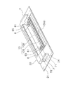
<可動パネル24の動作に関連する装置>
図4は、化粧パネルの斜視図である。図4に示すように、化粧パネル21の天井側の面上には、ヒンジ連結装置6及び昇降装置7が配置されている。
<Apparatus related to operation of
FIG. 4 is a perspective view of the decorative panel. As shown in FIG. 4, the hinge connecting device 6 and the
(ヒンジ連結装置6)
ヒンジ連結装置6は、空調室内機2が稼動するときに可動パネル24の一端を回動可能に支持し、可動パネル24をメンテナンス位置まで降下させるときに可動パネル24の一端の支持を解除する。具体的には、ヒンジ連結装置6のモータ65が回転することによって、回動レバー61が可動パネル24の長手方向と平行に移動し可動パネル24との連結又は連結解除を行う。ここでは、説明の便宜上、モータ65が回動レバー61を可動パネル24と連結する方向へ移動させるように回転することを正転とよび、モータ65が回動レバー61と可動パネル24との連結を解除する方向へ移動させるように回転することを逆転とよぶ。
(Hinge connection device 6)
The hinge coupling device 6 rotatably supports one end of the
可動パネル24の端部には、回動レバー61の支持軸と対峙する支持孔が設けられており、モータ65が正転し、回動レバー61の支持軸が可動パネル24の支持孔に挿入されたときは、回動レバー61と可動パネル24との連結が成立し、可動パネル24は、回動レバー61の回動軸を中心に回動することができる。
A support hole that faces the support shaft of the
一方、モータ65が逆転し、回動レバー61の支持軸が可動パネル24の支持孔から抜け出たときは、回動レバー61と可動パネル24との連結が解消され、可動パネル24は、回動レバー61の回動軸を中心に回動することができない。
On the other hand, when the
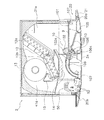
(昇降装置7)
図5は昇降装置内部の部品の配置図であり、図6は昇降装置のワイヤー巻き取り・繰り出し機構の分解斜視図である。図5、図6において、昇降装置7は、付勢部材70、ワイヤー71、滑車72、ボビン73、昇降モータ76及びケース78を有している。
(Elevating device 7)
FIG. 5 is an arrangement view of components inside the lifting device, and FIG. 6 is an exploded perspective view of a wire winding / feeding mechanism of the lifting device. 5 and 6, the
ワイヤー71の先端には、吊り金具708が接続されている。吊り金具708は、第1リング708aと第2リング708bとを有しており、第1リング708aはワイヤー71に接続され、第2リング708bは可動パネル24に連結される。
A suspension fitting 708 is connected to the tip of the
滑車72は、滑車部72aとカム部72bとが一体に成形されており、滑車部72aは、ワイヤー71を支え、ワイヤー71の移動に伴って回転する。カム部72bは、小径曲面と大径曲面とそれら両曲面を結ぶ平面とから成る。
The
ボビン73は、糸巻き形状をしており、ワイヤー71が巻き付く外周面73aと、外周面73aを両端から挟むフランジ73bとを有する。フランジ73bは、外周面73aよりも直径が大きく、外周面73aに巻き付くワイヤー71が外周面73aの両端から外れないように外周面73aの両端からワイヤー71を挟んでいる。
The
ボビン73の外周面73aには、円弧状の付勢部材70が対向するように配置される。付勢部材70は、円弧部70aと規制部70bとを有している。円弧部70aは、中心角180°以上の円弧形状を成し、弾性力によって外周面73aに沿うことができる。外周面73aにワイヤー71が巻き付いていないとき、円弧部70aは外周面73aに覆い被さり、外周面73aにワイヤー71が巻き付いているときは、巻き付いたワイヤー71に覆い被さってワイヤー71を外周面73aに押付ける。
An arcuate urging
規制部70bは、外周面73aに巻き付く直前のワイヤー71を外周面73aから外れた軌道を通らないように規制する。したがって、ワイヤー71が、外周面73aに巻き付く直前でボビン73の回転軸方向に振れたとき、規制部70bがワイヤー71の振れを外周面73aの幅以内となるように規制している。
The restricting
付勢部材70は樹脂製であるので、ワイヤー71の傷つき、ワイヤー71と付勢部材70との摩擦音も抑制される。但し、付勢部材70の材料は、樹脂に限定されるものではなく、耐久性を高めるために金属製にしてもよい。
Since the urging
昇降モータ76は、ステッピングモータであり、回転軸76aがボビン73を直接回転させる。昇降モータ76の回転数は、制御部から供給されるパルス数によって制御される。なお、制御部は、CPU、メモリ及びモータドライブ回路を搭載しており、昇降装置7から離れた他の位置に配置されている。昇降モータ76と制御部はワイヤーハーネスによって電気的に接続されている。
The raising / lowering
付勢部材70、ワイヤー71、滑車72、ボビン73及び昇降モータ76は、昇降装置7のワイヤー巻き取り・繰り出し機構を構成する主要部品である。昇降装置7には、このワイヤー巻き取り・繰り出し機構に加えて、第1スイッチ77及び第2スイッチ177をさらに備えている。
The urging
第1スイッチ77は、レバー77aを有するマイクロスイッチであり、レバー77aが押されることによってオンする。レバー77aは、常に滑車72のカム部72bと接触しており、カム部72bの大径曲面と対峙したときに押される。第1スイッチ77も、制御部とワイヤーハーネスによって電気的に接続されている。
The
第2スイッチ177は、レバー177aを有するマイクロスイッチであり、レバー177aがヒンジ部材177bを介して押されることによってオンする。可動パネル24が吸込口20aを閉じているとき、ヒンジ部材177bは可動パネル24に押されて回動し、第2スイッチ177のレバー177aを押している。可動パネル24が吸込口20aを開けているとき、ヒンジ部材177bは可動パネル24に押されていないので重力が作用する方向に回動し、第2スイッチ177のレバー177aから離れる。第2スイッチ177も、制御部とワイヤーハーネスによって電気的に接続されている。
The
ケース78には、滑車72を収納する第1収納部78aと、ボビン73を収納する第2収納部78bとが形成されている。ワイヤー71はボビン73の外周面73aに巻き付いた状態で、付勢部材70の円弧部70aはそのワイヤー71に覆い被さった状態でボビン73と共に第2収納部78bに収納される。
The
第1収納部78aと第2収納部78bとの間には、ワイヤー71が通るワイヤー通路78cが形成されており、付勢部材70の規制部70bはこのワイヤー通路78cのボビン73寄りに収納される。ワイヤー通路78cの滑車72寄りには、ワイヤー71をワイヤー通路78cの中央へ導く案内リブ78dが配置されている。
A wire passage 78c through which the
(昇降装置7の動作)
図5において、昇降装置7がワイヤー71を繰り出す場合、昇降モータ76はボビン73をCCW方向へ回転させる。これによって、ボビン73がワイヤー71を繰り出す方向に回転する。一方、昇降装置7がワイヤー71を巻き取る場合、昇降モータ76はボビン73をCW方向へ回転させる。これによって、ボビン73がワイヤー71を巻き取る方向に回転する。ワイヤー71の繰り出し量および巻き取り量は、昇降モータ76の回転量に比例しており、制御部が、昇降モータ76へ供給するパルス数を制御することによって、ワイヤー71の繰り出し量および巻き取り量が制御される。
(Operation of lifting device 7)
In FIG. 5, when the
ワイヤー71は吊り金具708を介して可動パネル24と連結されているため、ワイヤー71には常に張力が発生しており、ワイヤー71が繰り出されるとき、又はワイヤー71が巻き取られるとき、滑車部72aがワイヤー71との摩擦力によって回転する。このとき、カム部72bも回転するので、第1スイッチ77は、レバー77aがカム部72bの大径曲面と対峙したときにオン信号を発し、レバー77aが小径曲面と対峙したときにはオフ信号を発する。滑車72が回転している間は、オン信号とオフ信号が交互に発生し、これらの信号は、すべて制御部に入力される。
Since the
しかし、何らかの要因でワイヤー71が弛み張力がなくなった場合、例えば、メンテナンスのためにワイヤー71を繰り出して可動パネル24を降下させているときに、所定の繰り出し量に達する前に、可動パネル24がテーブルなどの上に着地して停止した場合には、ワイヤー71と滑車部72aとの摩擦力が減退し滑車72が停止する。このため、第1スイッチ77からは、オン信号又はオフ信号のいずれか一方が連続的に出力される。このとき、制御部では、昇降モータ76が回転しているときに第1スイッチ77からの信号が一定になっていることから、可動パネル24が何らかの障害物によって停止したと推定し、直ちに昇降モータ76を停止させる。
However, when the
(可動パネルの開閉動作)
図7は、可動パネルが吸込口を開いた状態の斜視図である。図7において、ヒンジ連結装置6が可動パネル24を連結した状態で、昇降装置7がワイヤー71を繰り出したとき、可動パネル24は自重によって降下する。しかし、可動パネル24の端部はヒンジ連結装置6に連結されているので、可動パネル24は回動レバー61の回動軸を中心として、吸込口20aを開く方向へ回動する。
(Movable panel open / close operation)
FIG. 7 is a perspective view of a state in which the movable panel opens the suction port. In FIG. 7, when the
一方、昇降装置7がワイヤー71を巻き取るとき、可動パネル24は上昇するが、可動パネル24の端部がヒンジ連結装置6に連結されているので、可動パネル24は回動レバー61の回動軸を中心として、吸込口20aを閉じる方向へ回動する。
On the other hand, when the
(可動パネルの昇降動作)
図8は、可動パネルが降下している状態の斜視図である。図8において、ヒンジ連結装置6が可動パネル24の端部との連結を解除し、昇降装置7がワイヤー71を繰り出したとき、可動パネル24は自重によって降下する。一方、昇降装置7がワイヤー71を巻き取るとき、可動パネル24は上昇し、可動パネル24が吸込口20aを閉じる。
(Elevating operation of movable panel)
FIG. 8 is a perspective view of the movable panel in a lowered state. In FIG. 8, when the hinge connecting device 6 releases the connection with the end of the
<特徴>
(1)
昇降装置7は、昇降モータ76によってボビン73を回転させ、ボビン73の外周面73aにワイヤー71を巻き付ける。ボビン73の外周面73aに巻き付いたワイヤー71には、円弧状に成形された樹脂製の付勢部材70が弾性力によって覆い被さり、ワイヤー71を外周面73a側に押付ける。ボビン73がワイヤー71を巻き取るとき、山状に巻き付くワイヤー71を付勢部材70が押えるので、ワイヤー71が外周面73aに均等に巻き付くようになり、ワイヤー71がボビン73を越えて外れることが防止される。また、巻き付いたワイヤー71の高さが変化したときでも、ワイヤー71と付勢部材70との隙間が瞬時に詰められるので、ワイヤー71が緩んで解けることが防止される。
<Features>
(1)
The
(2)
付勢部材70には、ワイヤー71がボビン73に巻き付く前にワイヤー71を外周面73aへ導く規制部70bを有している。この規制部70bは、ボビン73の回転時にボビン73が回転軸方向に振れることを防止する機能も有しているので、ワイヤー71がボビン73に安定して巻き付く。
(2)
The urging
以上のように、本発明によれば、空気吸込口の近傍にワイヤーを介して吊られる可動パネルをワイヤーの動作によって昇降させる空調室内機の可動パネル昇降装置に有用である。 As described above, according to the present invention, the movable panel lifting and lowering device for an air conditioning indoor unit that lifts and lowers the movable panel suspended through the wire in the vicinity of the air suction port by the operation of the wire is useful.
2 空調室内機
20 本体
20a 吸込口
24 可動パネル
70 付勢部材
70a 円弧部
70b 規制部
71 ワイヤー
73 ボビン(巻付部材)
73a 外周面
76 モータ
2 Air-conditioning
73a outer
Claims (8)
モータ(76)と、
前記モータ(76)によって回転駆動され外周面(73a)に前記ワイヤー(71)が巻き付く巻付部材(73)と、
巻き付いた状態の前記ワイヤー(71)に前記巻付部材(73)の外周側から接触して前記ワイヤー(71)を前記巻付部材(73)の前記外周面(73a)に押付ける付勢部材(70)と、
を備えた、
ワイヤー巻き取り・繰り出し装置(7)。 A wire winding / unwinding device for winding or unwinding a wire (71) connected to an object,
A motor (76);
A winding member (73) that is rotationally driven by the motor (76) and the wire (71) is wound around the outer peripheral surface (73a);
A biasing member that contacts the wire (71) in a wound state from the outer peripheral side of the winding member (73) and presses the wire (71) against the outer peripheral surface (73a) of the winding member (73). (70),
With
Wire take-up and feeding device (7).
請求項1に記載のワイヤー巻き取り・繰り出し装置(7)。 The urging member (70) follows the height change from the outer peripheral surface (73a) of the wire (71) by elastic deformation,
A wire take-up / feeding device (7) according to claim 1.
請求項1に記載のワイヤー巻き取り・繰り出し装置(7)。 The biasing member (70) is made of resin.
A wire take-up / feeding device (7) according to claim 1.
請求項1に記載のワイヤー巻き取り・繰り出し装置(7)。 The biasing member (70) is made of metal;
A wire take-up / feeding device (7) according to claim 1.
請求項1に記載のワイヤー巻き取り・繰り出し装置(7)。 The longitudinal section of the biasing member (70) is arcuate,
A wire take-up / feeding device (7) according to claim 1.
請求項5に記載のワイヤー巻き取り・繰り出し装置(7)。 The urging member (70) is formed with an arc (70a) having a central angle of 180 ° or more with respect to the center of the arc shape.
The wire winding / unwinding device (7) according to claim 5.
請求項5に記載のワイヤー巻き取り・繰り出し装置(7)。 The urging member (70) is provided with a restricting member (70b) for restricting the deflection of the wire (71) in the central axis direction of winding or feeding.
The wire winding / unwinding device (7) according to claim 5.
前記ワイヤー(71)を動作させる請求項1から請求項7のいずれか1項に記載のワイヤー巻き取り・繰り出し装置(7)を備えた、
空調室内機の可動パネル昇降装置。 Air conditioning in which the movable panel (24) suspended via the wire (71) is moved up and down and / or the air suction port (20a) is opened and closed by the operation of the wire (71) in the vicinity of the air suction port (20a). A movable panel lifting device for an indoor unit,
The wire winding and unwinding device (7) according to any one of claims 1 to 7, wherein the wire (71) is operated.
A movable panel lifting device for air conditioning indoor units.
Priority Applications (1)
| Application Number | Priority Date | Filing Date | Title |
|---|---|---|---|
| JP2008186411A JP4968205B2 (en) | 2008-07-17 | 2008-07-17 | Wire winding / unwinding device, and movable panel lifting / lowering device for air conditioner indoor unit equipped with the wire winding / unwinding device |
Applications Claiming Priority (1)
| Application Number | Priority Date | Filing Date | Title |
|---|---|---|---|
| JP2008186411A JP4968205B2 (en) | 2008-07-17 | 2008-07-17 | Wire winding / unwinding device, and movable panel lifting / lowering device for air conditioner indoor unit equipped with the wire winding / unwinding device |
Publications (2)
| Publication Number | Publication Date |
|---|---|
| JP2010025416A true JP2010025416A (en) | 2010-02-04 |
| JP4968205B2 JP4968205B2 (en) | 2012-07-04 |
Family
ID=41731429
Family Applications (1)
| Application Number | Title | Priority Date | Filing Date |
|---|---|---|---|
| JP2008186411A Expired - Fee Related JP4968205B2 (en) | 2008-07-17 | 2008-07-17 | Wire winding / unwinding device, and movable panel lifting / lowering device for air conditioner indoor unit equipped with the wire winding / unwinding device |
Country Status (1)
| Country | Link |
|---|---|
| JP (1) | JP4968205B2 (en) |
Citations (10)
| Publication number | Priority date | Publication date | Assignee | Title |
|---|---|---|---|---|
| JPS6044495A (en) * | 1983-08-18 | 1985-03-09 | 株式会社安田製作所 | Automatic tail capturing device for manual winding winch |
| JPS62202440U (en) * | 1986-06-16 | 1987-12-24 | ||
| JPH0763406A (en) * | 1993-08-30 | 1995-03-10 | Daikin Ind Ltd | Lifting device for air conditioner |
| JPH08110086A (en) * | 1994-10-12 | 1996-04-30 | Daikin Ind Ltd | Elevation unit vertically moving apparatus for air conditioner |
| JPH0930792A (en) * | 1995-07-18 | 1997-02-04 | Toyota Autom Loom Works Ltd | Winch unit of forklift |
| JPH10196999A (en) * | 1996-12-27 | 1998-07-31 | Konami Kk | Ceiling embedded type air conditioning equipment |
| JP2000121145A (en) * | 1998-10-16 | 2000-04-28 | Daikin Ind Ltd | Air conditioner |
| JP2000289990A (en) * | 1999-03-31 | 2000-10-17 | Hitachi Constr Mach Co Ltd | Rope winch |
| JP2004250155A (en) * | 2003-02-19 | 2004-09-09 | Hitachi Sumitomo Heavy Industries Construction Crane Co Ltd | Rope winch |
| JP2006043850A (en) * | 2004-08-06 | 2006-02-16 | Mitsutoyo Corp | Cassette type wire feeder |
-
2008
- 2008-07-17 JP JP2008186411A patent/JP4968205B2/en not_active Expired - Fee Related
Patent Citations (10)
| Publication number | Priority date | Publication date | Assignee | Title |
|---|---|---|---|---|
| JPS6044495A (en) * | 1983-08-18 | 1985-03-09 | 株式会社安田製作所 | Automatic tail capturing device for manual winding winch |
| JPS62202440U (en) * | 1986-06-16 | 1987-12-24 | ||
| JPH0763406A (en) * | 1993-08-30 | 1995-03-10 | Daikin Ind Ltd | Lifting device for air conditioner |
| JPH08110086A (en) * | 1994-10-12 | 1996-04-30 | Daikin Ind Ltd | Elevation unit vertically moving apparatus for air conditioner |
| JPH0930792A (en) * | 1995-07-18 | 1997-02-04 | Toyota Autom Loom Works Ltd | Winch unit of forklift |
| JPH10196999A (en) * | 1996-12-27 | 1998-07-31 | Konami Kk | Ceiling embedded type air conditioning equipment |
| JP2000121145A (en) * | 1998-10-16 | 2000-04-28 | Daikin Ind Ltd | Air conditioner |
| JP2000289990A (en) * | 1999-03-31 | 2000-10-17 | Hitachi Constr Mach Co Ltd | Rope winch |
| JP2004250155A (en) * | 2003-02-19 | 2004-09-09 | Hitachi Sumitomo Heavy Industries Construction Crane Co Ltd | Rope winch |
| JP2006043850A (en) * | 2004-08-06 | 2006-02-16 | Mitsutoyo Corp | Cassette type wire feeder |
Also Published As
| Publication number | Publication date |
|---|---|
| JP4968205B2 (en) | 2012-07-04 |
Similar Documents
| Publication | Publication Date | Title |
|---|---|---|
| JP4821807B2 (en) | Air conditioning indoor unit | |
| JP2009293807A (en) | Movable panel for air conditioner indoor unit | |
| JP5327014B2 (en) | Air conditioner | |
| TWI386546B (en) | Blinds device | |
| JP2009068752A (en) | Indoor machine of air conditioning device | |
| JP3087736B2 (en) | Air conditioner | |
| JP4968205B2 (en) | Wire winding / unwinding device, and movable panel lifting / lowering device for air conditioner indoor unit equipped with the wire winding / unwinding device | |
| JP4433076B2 (en) | Air conditioning indoor unit | |
| JP5333022B2 (en) | Air conditioner indoor unit | |
| JP4341711B2 (en) | Air conditioner indoor unit | |
| JP4915392B2 (en) | Air conditioning indoor unit and method of moving panel of air conditioning indoor unit | |
| JP2010043839A (en) | Ceiling-mounted type air conditioner | |
| JP2009216384A (en) | Indoor device of air conditioner | |
| JPH11325555A (en) | Air conditioner | |
| JP5211865B2 (en) | Air-conditioning indoor unit movable panel | |
| JP2002061876A (en) | Ceiling embedment type air conditioner | |
| JP2010043842A (en) | Indoor unit of air conditioner | |
| JP5061783B2 (en) | Air conditioner indoor unit | |
| JP4131738B2 (en) | Embedded ceiling air conditioner. | |
| JP4935774B2 (en) | Ceiling-mounted air conditioner | |
| JP3795950B2 (en) | Embedded ceiling air conditioner | |
| JP5239629B2 (en) | Air conditioning indoor unit | |
| JP5493495B2 (en) | Air conditioner indoor unit | |
| JP4145325B2 (en) | Embedded ceiling air conditioner. | |
| JP2013234814A (en) | Air conditioner |
Legal Events
| Date | Code | Title | Description |
|---|---|---|---|
| A977 | Report on retrieval |
Free format text: JAPANESE INTERMEDIATE CODE: A971007 Effective date: 20110426 |
|
| A131 | Notification of reasons for refusal |
Free format text: JAPANESE INTERMEDIATE CODE: A131 Effective date: 20110614 |
|
| A521 | Request for written amendment filed |
Free format text: JAPANESE INTERMEDIATE CODE: A523 Effective date: 20110811 |
|
| TRDD | Decision of grant or rejection written | ||
| A01 | Written decision to grant a patent or to grant a registration (utility model) |
Free format text: JAPANESE INTERMEDIATE CODE: A01 Effective date: 20120306 |
|
| A01 | Written decision to grant a patent or to grant a registration (utility model) |
Free format text: JAPANESE INTERMEDIATE CODE: A01 |
|
| A61 | First payment of annual fees (during grant procedure) |
Free format text: JAPANESE INTERMEDIATE CODE: A61 Effective date: 20120319 |
|
| FPAY | Renewal fee payment (event date is renewal date of database) |
Free format text: PAYMENT UNTIL: 20150413 Year of fee payment: 3 |
|
| R151 | Written notification of patent or utility model registration |
Ref document number: 4968205 Country of ref document: JP Free format text: JAPANESE INTERMEDIATE CODE: R151 |
|
| FPAY | Renewal fee payment (event date is renewal date of database) |
Free format text: PAYMENT UNTIL: 20150413 Year of fee payment: 3 |
|
| LAPS | Cancellation because of no payment of annual fees |