JP2010025220A - Torque limiter and actuator loaded with the same - Google Patents
Torque limiter and actuator loaded with the same Download PDFInfo
- Publication number
- JP2010025220A JP2010025220A JP2008186944A JP2008186944A JP2010025220A JP 2010025220 A JP2010025220 A JP 2010025220A JP 2008186944 A JP2008186944 A JP 2008186944A JP 2008186944 A JP2008186944 A JP 2008186944A JP 2010025220 A JP2010025220 A JP 2010025220A
- Authority
- JP
- Japan
- Prior art keywords
- ball
- torque limiter
- torque
- rotation
- clutch plate
- Prior art date
- Legal status (The legal status is an assumption and is not a legal conclusion. Google has not performed a legal analysis and makes no representation as to the accuracy of the status listed.)
- Granted
Links
Images


Abstract
Description
本発明は、クラッチ部分にボールを使用したトルクリミッタに関し、特に、バルブ用アクチュエータに好適なトルクリミッタとこのトルクリミッタを搭載したバルブ用アクチュエータに関する。 The present invention relates to a torque limiter using a ball for a clutch portion, and more particularly to a torque limiter suitable for a valve actuator and a valve actuator equipped with the torque limiter.
この種のトルクリミッタをバルブ用アクチュエータに搭載した場合、このバルブ用アクチュエータは、バルブへの異物の噛み込みなどにより出力軸に過負荷が加わったときにモータからの動力伝達を遮断して出力軸を保護でき、また、動力伝達時には、高い精度でトルクを伝達し、トルク調整も容易であるため高い精度で弁体を駆動制御できるようになっている。このため、トルクリミッタは、特に大型をはじめとするバルブ用アクチュエータに搭載されることが多い。 When this type of torque limiter is mounted on a valve actuator, this valve actuator shuts off the power transmission from the motor when an overload is applied to the output shaft due to foreign matter being caught in the valve. Further, when transmitting power, torque is transmitted with high accuracy and torque adjustment is easy, so that the valve body can be driven and controlled with high accuracy. For this reason, the torque limiter is often mounted on a valve actuator including a large size.
このようなトルクリミッタとしては、例えば、特許文献1のオーバーロードクラッチや特許文献2のボールクラッチがある。同文献1、2のトルクリミッタにおいては、図9に示すように、ボール1はボールガイド2の上を移動し、このボールガイド2には直線状の傾斜部3と平面部4が設けられ、この傾斜部3と平面部4とを結ぶ接続部分にはエッジ状の角部5が形成されている。また、ボール1は、ボールガイド2との他方側において図示しないボール保持板に保持されている。
Examples of such a torque limiter include an overload clutch disclosed in
また、特許文献3のトルクリミターでは、ボールガイドのV溝(ポケット部)におけるテーパ面が第1、第2傾斜面の2段の傾斜面として形成されている。同文献3は、この2段構成の傾斜面により、傾斜面同士の交差角度や、傾斜面と平面部との交差角度が大きくなっている。 Further, in the torque limiter of Patent Document 3, the tapered surface in the V groove (pocket portion) of the ball guide is formed as a two-step inclined surface of the first and second inclined surfaces. In the literature 3, the two-stage inclined surface increases the intersection angle between the inclined surfaces and the intersection angle between the inclined surface and the plane portion.
しかしながら、特許文献1、2のトルクリミッタをバルブ用アクチュエータに搭載した場合、過負荷発生時にボールの移動が不安定になり、動力伝達の遮断が確実におこなわれずに誤作動を生じることがあった。このときのボールの動作を、図9において説明する。
However, when the torque limiter disclosed in
図9(a)において、特許文献1、2のトルクリミッタは、過負荷発生時にボール1が傾斜部3を移動し、角部5を通過した後に平面部4に移動することにより動力伝達の遮断がおこなわれるようになっている。先ず、ボール1が傾斜部3を移動する際には、ボール1と傾斜部3との接触位置P1は、ボール1の移動方向に対して変化せず、ボール1の最下点Bから角度θ傾いた位置となる。
In FIG. 9A, the torque limiters disclosed in
続いて、図9(b)に示すように、ボール1が角部5に達すると、接触位置がP2の位置となり、ボール1は、接触位置P2が最下点Bの位置に移りながら、この接触位置P2を中心として瞬間的に回転する。このため、ボール1は、ボールガイド2の上の転動や摺動を伴うことなく瞬間的に二点鎖線の位置まで上昇移動する。
この瞬間的なボール1の移動により、作動トルクが瞬間的に急上昇するため、ボール1を弾発付勢している図示しないスプリングが反応できずにボール1を押し戻して動力伝達の遮断ができなくなることがある
Subsequently, as shown in FIG. 9 (b), when the
This momentary movement of the
また、上記のように、ボール1が傾斜部3を移動する際には接触位置P1が変化しないため、スプリングの弾発付勢力は、ボール1が角部5に達するまで比例的に増加することになる。このため、ボール1は、弾発付勢力によって押し戻され易くなっている。また、ボール1の押し戻しを防ぐためにスプリングの弾発付勢力を小さくすると、ボール1を傾斜部3に保持する力が弱くなるため、所定のトルクに達する前に動力伝達が遮断される危険性が生じる。また、長期に亘ってこのトルクリミッタを使用した場合にも、角部5の摩耗が激しくなって所定トルク以下で動力伝達の遮断がおこなわれることがある。
Further, as described above, when the
更に、このトルクリミッタは、ボール1が傾斜部3を十分に助走することなく直ちに角部5を乗り越えて平面部4に進む構造であるためスプリングの弾発力が弱く設定され、且つ、ボール1が角部5を乗り越えることができるようにするために傾斜部3の深さが浅く形成されている。この構造により、ボール1が角部5を乗り越えるときのボールガイド2に対するボール保持板のリフト量が小さくなっていた。
Further, since this torque limiter has a structure in which the
以上の理由により、同文献1、2のトルクリミッタをバルブ用アクチュエータに搭載した場合、動力伝達の遮断が確実におこなわれずに出力軸に負荷が加わり続けて故障の原因となったり、或は、通常の動力伝達時に動力伝達の遮断がおこなわれてバルブ駆動時に停止する危険性があった。また、ボール保持板のリフト量が小さいと、このリフト量を利用したリミットスイッチ等による動力遮断の検出が難しくなったり、利用できるリミットスイッチが限定されるという問題があった。
For the above reasons, when the torque limiter described in the
一方、特許文献3は、2段の傾斜面を設けることにより、この傾斜面をボールが移動するときの衝撃を小さくし、また、摩耗や変形を生じ難くしようとするものである。しかし、同文献3は、ボールがエッジ状の角部を乗り越える構造である以上、同文献1、2と同様に瞬間的な作動トルクの急上昇を防ぐことは難しい。
また、このトルクリミターは、テーパ面が2段に形成されていることから、作動トルクの急上昇が生ずる部位が2箇所に増えてしまうことに加え、第2傾斜面が浅い傾斜角によって設けられているためボールがこの部分で進退を繰り返して動作が不安定になるおそれもある。
これらの理由により、同文献3のトルクリミターもバルブ用アクチュエータに適用することには適していない。
On the other hand, Patent Document 3 intends to reduce the impact when a ball moves on this inclined surface by providing two steps of inclined surfaces, and to prevent wear and deformation. However, since the document 3 has a structure in which the ball goes over the edge-shaped corner, it is difficult to prevent an instantaneous increase in the operating torque as in the
In addition, since the torque limiter is formed in two stages, the second inclined surface is provided with a shallow inclination angle in addition to the fact that the number of portions where the operating torque rapidly increases is increased to two. Therefore, there is a possibility that the ball repeats advancing and retreating at this portion and the operation becomes unstable.
For these reasons, the torque limiter disclosed in Document 3 is not suitable for application to a valve actuator.
本発明は、従来の課題点を解決するために開発したものであり、その目的とするところは、通常時には確実に動力を伝達できると共に、過負荷発生時には作動トルクの急上昇を抑制して確実に動力伝達を遮断でき、しかも、動力伝達の遮断時にはボールのリフト量を大きく確保できるトルクリミッタであり、バルブ用アクチュエータに搭載したときには、優れた安定性によりその機能性を発揮できるトルクリミッタとこれを搭載したバルブ用アクチュエータを提供することにある。 The present invention has been developed in order to solve the conventional problems. The purpose of the present invention is to transmit power reliably during normal operation and to reliably suppress sudden increase in operating torque when overload occurs. This is a torque limiter that can shut off power transmission, and can secure a large ball lift when power transmission is cut off.When mounted on a valve actuator, this torque limiter can exhibit its functionality with excellent stability. The object is to provide an on-board valve actuator.
前記目的を達成するため、請求項1に係る発明は、ボールと、このボールが移動可能な溝部を有するボールガイドと、ボールが装着され、このボールによりボールガイドとの回転を伝達又は遮断するクラッチ板とを有するトルクリミッタにおいて、ボールガイドに、通常時にはクラッチ板との間にボールを保持して回転を伝達すると共に、過負荷発生時にはボールが転動又は摺動しながら乗り上げて回転伝達を遮断するアール面部を設けたトルクリミッタである。
In order to achieve the above object, the invention according to
請求項2に係る発明は、ボールガイドに、回転方向に対して傾斜する斜面部を有する溝部とこの溝部の頂部側に平面部とを設け、アール面部を溝部から平面部に向けて連設したトルクリミッタである。
In the invention according to
請求項3に係る発明は、溝部側におけるアール面部の始点を、回転伝達時のボールの近傍位置に配置したトルクリミッタである。 The invention according to claim 3 is a torque limiter in which the starting point of the rounded surface portion on the groove portion side is disposed in the vicinity of the ball at the time of rotation transmission.
請求項4に係る発明は、ボールが溝部に収納されたときのこのボールの下方頂部から、ボールが平面部に乗り上げたときのこのボールの下方頂部までのボールガイドにおける軸方向の長さを、ボールガイドとクラッチ板とが離間するときの離間距離としたトルクリミッタである。 The invention according to claim 4 is the axial length of the ball guide from the lower top of the ball when the ball is housed in the groove to the lower top of the ball when the ball rides on the flat surface. The torque limiter is a separation distance when the ball guide and the clutch plate are separated.
請求項5に係る発明は、請求項1乃至4の何れか1項に記載のトルクリミッタをバルブ用アクチュエータに搭載したトルクリミッタである。
The invention according to claim 5 is a torque limiter in which the torque limiter according to any one of
請求項1に係る発明によると、通常時には確実に動力を伝達でき、また、過負荷発生時には作動トルクの急上昇を抑制して確実に動力伝達を遮断できるトルクリミッタである。しかも、動力伝達の遮断時にはボールのリフト量を大きく確保できるため、この動力遮断をリミットスイッチ等を用いて容易に検出でき、例えば、バルブ用アクチュエータに搭載したときに優れた安定性によりその機能性を発揮できるトルクリミッタである。 According to the first aspect of the present invention, the torque limiter can reliably transmit power during normal operation, and can reliably block power transmission by suppressing a sudden increase in operating torque when an overload occurs. In addition, when the power transmission is interrupted, a large amount of ball lift can be secured, so this power interrupt can be easily detected by using a limit switch, etc. It is a torque limiter that can exhibit
請求項2に係る発明によると、動力伝達時から動力遮断時にかけてスムーズに動作でき、また、簡単な加工により容易に製作できるトルクリミッタである。 According to the second aspect of the present invention, the torque limiter can operate smoothly from the time of power transmission to the time of power interruption, and can be easily manufactured by simple processing.
請求項3に係る発明によると、動力伝達の遮断時においてボールが移動する際に作動トルクが急上昇することを抑えて、安定して動作するトルクリミッタである。 According to the third aspect of the present invention, the torque limiter operates stably while suppressing a sudden increase in operating torque when the ball moves when power transmission is interrupted.
請求項4に係る発明によると、動力伝達の遮断時にボールが溝部のアール面部を移動することでボールガイドとクラッチ板とを緩やかに離間させることができ、長い離間距離を利用して動力遮断時の信号を正確に検出できるトルクリミッタである。 According to the invention of claim 4, the ball guide and the clutch plate can be gently separated by moving the rounded surface portion of the groove portion when the power transmission is interrupted, and when the power is interrupted using a long separation distance. This is a torque limiter that can accurately detect the signal.
請求項5に係る発明によると、動力伝達時には高精度によりバルブを回転制御でき、また、過負荷発生時にはモータからの動力伝達を遮断して出力軸を保護して、優れた機能性を発揮しながら安全に使用できるトルクリミッタを搭載したバルブ用アクチュエータである。更に、このトルクリミッタを搭載したバルブ用アクチュエータは、大型であってもよい。 According to the invention of claim 5, when the power is transmitted, the rotation of the valve can be controlled with high accuracy, and when the overload occurs, the power transmission from the motor is interrupted to protect the output shaft, thereby exhibiting excellent functionality. It is a valve actuator equipped with a torque limiter that can be used safely. Furthermore, the valve actuator equipped with this torque limiter may be large.
以下に、本発明におけるトルクリミッタとこのトルクリミッタを搭載したバルブ用アクチュエータの一実施形態を図面に基づいて詳細に説明する。
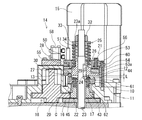
バルブ用アクチュエータ本体14は、モータ15と、このモータ15からの回転を減速する1次側のギア16やピニオン部材17等を有する歯車減速機構18と、歯車減速機構18からの回転を出力する図示しない出力軸とを有している。モータ15の回転は、歯車減速機構18を介して出力軸に伝達される。出力軸は、図示しないバルブのステムと接続されており、この出力軸の回転は、ステムと接続された図示しない弁体に伝達される。これにより、バルブが開閉又は中間開度に制御可能となる。
本発明のトルクリミッタは、このバルブ用アクチュエータ本体14に搭載されることに適しており、例えば、このバルブ用アクチュエータ本体14のギア16と歯車減速機構18の中間段に配設される中間歯車20との間に搭載される。
Hereinafter, an embodiment of a torque limiter according to the present invention and a valve actuator equipped with the torque limiter will be described in detail with reference to the drawings.
The
The torque limiter of the present invention is suitable for being mounted on the valve actuator
トルクリミッタ本体10は、クラッチユニット21と、ピニオンユニット22とを有している。
クラッチユニット21は、ギア16の回転軸であるシャフト23の上部にキー24を介して設けられ、クラッチ部12と、スプリング部25、及びカム部26とを有している。
The
The
クラッチ部12は、ギア16とピニオン部材17との間に後述のボールガイド11と同軸に回転可能に設けられ、このボールガイド11の回転を伝達又は遮断するクラッチ板27と、クラッチ板27の上面の凸部28に装着された環状の磁性体29により構成される。クラッチ板27は、下面側に略半球凹状のボール収容部30が複数箇所に等間隔に形成され、このボール収容部30にボール13が回転可能に装着されている。
The
ボール13は金属製であり、クラッチ板27に装着された状態でこのクラッチ板27とボールガイド11との間に位置している。ボール13は、クラッチ板27を常に水平状態に維持し、傾くことを防止するために3個以上の個数とすることがよい。
The
磁性体29は、磁石からなり、ボール収容部30付近に配置されることにより、ボール13を磁力により磁着(吸着)してクラッチ板27に保持する機能を有している。これにより、バルブ用アクチュエータ本体14を組付ける際にボール13をクラッチ部12と一体化できるようになっている。また、後述するように、手動操作時にも、ボール13はクラッチ板27に保持された状態が維持されるようになっている。
The
スプリング部25は、ナット32とスプリング押え33とスプリング部材34とにより構成される。ナット32は、シャフト23の上部に形成されたおねじ部23aに螺合されている。また、スプリング押え33は、シャフト23の外周側に装着され、且つ、ナット32の下面に当接した状態で配置されている。スプリング部材34は、異線形ばね形状により短く形成され、スプリング押え33とクラッチ板27との間に弾発付勢した状態で装着されている。スプリング部25は、スプリング部材34の弾発付勢力によりクラッチ板27をピニオンユニット22側に押圧しており、この押圧力は、ナット32の締め込み具合を変えることにより調整可能になっている。トルクリミッタ本体10が回転伝達を遮断するときの作動トルクは、スプリング部材34の弾発付勢力に比例するようになっている。
The
ピニオンユニット22は、ギア16とクラッチユニット21との中間位置であり、且つ、シャフト23の外周側に配設されている。本実施形態では、図のように、クラッチユニット21を上方側、ピニオンユニット22を下方側に配置することで、歯車減速機構18と図示しない制御用スイッチ類の区画を分けて、調整作業をしやすくしているが、この配置は逆であってもよい。ピニオンユニット22は、ピニオン部材17とボールガイド11とを有している。
The
ピニオン部材17は、図示しないベアリングを介してシャフト23に回転自在に取付けられ、かつ、中間歯車20と噛合して取付けられている。
The
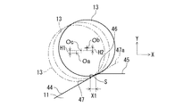
ボールガイド11は、図3、4に示すように、ピニオン部材17の上面側に取付ねじ43により固定され、クラッチ部12の出力側に回転軸23を中心に回転可能に設けられる。また、この回転軸23には、ボール13が移動可能な溝部44が設けられている。
As shown in FIGS. 3 and 4, the ball guide 11 is fixed to the upper surface side of the
溝部44は、略V字形状に形成され、所定間隔で形成されている。本実施形態においては、この溝部44は、ボール13の個数に対応してボールガイド11の3箇所に形成されている。溝部44には、回転方向に対して傾斜する斜面部47と、頂部側においては平面部45とが形成され、この溝部44から平面部45に向けてアール面部46が連設されている。
The
上記のように構成されることで、トルクリミッタ本体10は、通常時には、スプリング部材34の押圧により溝部44とクラッチ板27との間にボール13を保持してクラッチ部12からボールガイド11に回転を伝達する。また、出力軸に過負荷が生じた時には、クラッチ部12に対してボールガイド11が回転しようとする作動トルクが発生してボール13がアール面部46を乗り上げることにより、ボールガイド11とクラッチ部12との回転伝達が遮断される。このとき、ボール13は、アール面部46を転動又は摺動するように平面部45まで移動する。
また、ボール13の乗り上げにより、クラッチ板27がカム部26側に移動したときには、クラッチ板27とカム部26とが磁性体29により磁着するようになっている。
With the configuration described above, the
Further, when the
アール面部46の溝部44側における始点Sは、回転伝達時にボール13が位置する近傍位置に配設されている。これにより、斜面部47が短く形成され、過負荷発生時において、ボール13が溝部44からアール面部46に迅速に移動できるようになっている。
The starting point S on the side of the
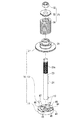
また、図2において、ボール13が溝部44に収納されたときのこのボール13の下方頂部Cから、ボール13が平面部45に乗り上げたときのこのボール13の下方頂部Cまでのボールガイド11における軸方向の長さを、ボールガイド11とクラッチ板27とが離間するときの離間距離としている。
In FIG. 2, in the ball guide 11 from the lower top C of the
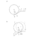
ここで、アール面部46とボール13との関係を記す。図7において、アール面部46の円弧の半径をR、ボール半径をrとすると、円弧半径Rが大きいほどボール13がアール面部46を乗り上げるときの上昇速度が低下し、ボール半径rが小さいほどこの上昇速度が低下する。また、ボール半径rを大きくした場合、円弧半径Rを同率で大きくすることによってボールが円弧半径Rを移動するときの速度を一定の水準に保てるようになっている。
また、離間距離Lを大きくする場合や、大きい作動トルクで作動させる際にヘルツ応力(ボール13とアール面部46とが押付けられたときにその接触点に働く集中応力)を下げたい場合には、ボール半径rを大きくすることが有効である。
Here, the relationship between the
When the separation distance L is increased or when it is desired to reduce Hertz stress (concentrated stress acting on the contact point when the
図7(a)においては、円弧半径R=ボール半径r×10とした場合を示している。この場合、作動トルクが上昇しやすくなる斜面部46の長さh1が短くなることで作動トルクが比例的に上昇する範囲が小さくなる。
一方、図7(b)においては、円弧半径R=ボール半径r×2とした場合を示している。この場合、斜面部46の長さh2が図7(a)に比較して長くなることで作動トルクが比例的に上昇する範囲が大きくなる。
FIG. 7A shows a case where the arc radius R = ball radius r × 10. In this case, the range in which the operating torque rises proportionally is reduced by shortening the length h1 of the
On the other hand, FIG. 7B shows a case where the arc radius R = the ball radius r × 2. In this case, the range in which the operating torque is proportionally increased is increased by increasing the length h2 of the
このように、作動トルクは、斜面部47の長さに比例して上昇するため、図7(b)のように、斜面部47に対してアール面部46の割合が少ない場合には、高負荷で使用する場合などに負荷が増減してボール13が斜面部47を繰り返し移動することがある。このため、この動作域内で摩耗が激しくなる。
これに対し、図7(a)のように、斜面部47に対してアール面部46の割合が多い場合には、このアール面部46までのボール13の移動量が少なくなり、ボール13の無駄な移動が最小限に抑えられる。そのため、ボール13の変位及び速度が一定水準に近づいて安定して作動し、耐久性の向上が図られる。
As described above, the operating torque increases in proportion to the length of the
On the other hand, as shown in FIG. 7A, when the ratio of the
従って、円弧半径Rは、ボール半径rに対して大きく形成して斜面部47を短くし、アール面部46の始点Sを回転遮断時のボール13の移動開始位置にできるだけ近づけることが望ましい。この場合、斜面部47を設けること無く、溝部44に続けて直接アール面部46を設けるようにしてもよい。更に、円弧半径Rは、スプリング部材34の弾発付勢力やクラッチ板27の回転速度等にも基づいて設定するようにし、ボール13が溝部44を確実に乗り越えるように設定する。
また、離間距離Lは、ボール13が溝部44におけるアール面部46を移動する距離とボール13の直径とにより影響を受けるため、これらを適宜設定して必要なリフト量を確保する必要もある。
Therefore, it is desirable that the arc radius R is formed larger than the ball radius r to shorten the
Further, since the separation distance L is affected by the distance that the
本実施形態においては、ボール半径r:円弧半径Rを1:5以上とし、これにより、リフト量を大きく確保でき、また、ヘルツ応力を下げて安定した動作を行い得るようになっている。更に、図7(b)において、斜面部47の平面部45からの角度を圧力角αとし、この圧力角αが例えば30°である場合には、圧力角30°の斜面部47をボール13が乗り上げる上昇速度と円弧半径Rをボール13が乗り上げるときの上昇速度の最大値とを同等にするために、ボール半径r:円弧半径Rを1:2以上に設けようにする。
In the present embodiment, the ball radius r: arc radius R is set to 1: 5 or more, so that a large lift amount can be secured, and a stable operation can be performed by reducing the Hertz stress. Further, in FIG. 7B, the angle of the
なお、カム部26は、環状のカム部材50とピン51とにより構成される。カム部材50は、断面逆L字型の上カム板53と、板状の下カム板54からなり、上カム板53の下部に形成された段部53aに下カム板54を係止することにより、断面コの字型の開口部55が外周側に向けて形成される。上カム板53と下カム板54は、シャフト23の軸方向に配置された2本のねじ56、56により固定されている。ピン51は、カム部材50の上面に装着され、カム部材50の回転とともに円周方向に移動してリミットスイッチ58と接触するようになっている。これにより、カム部26は、過負荷発生時にクラッチ部12と連動して、このクラッチ部12の回転方向に回転してリミットスイッチ58を作動できるようになっている。また、カム部26は、保持部材60により保持されている。
The
保持部材60は、略環状に形成され、取付ボルト61によりアクチュエータ14のベース体62に固定されている。保持部材60には2条の図示しない円弧状溝が形成され、これらの円弧状溝は、同じ形状になっている。円弧状溝には、上記の2本のねじが挿入され、これにより、カム部材50が保持部材60に対して円弧状溝の範囲内において回転自在に保持されている。しかも、カム部材50は、外周面側が保持部材50の内周面側に接することにより芯出し保持され、径方向への振れが防がれている。
The holding
保持部材50におけるねじと円弧状溝の非回転規制側との間には、図示しない2つの戻りばねが装着されている。戻りばねは、等しい弾発力であり、一端側が円弧状溝の非回転規制側の端部側に固定されている。この戻りばねにより、カム部を自動復帰させている。
Two return springs (not shown) are mounted between the screw in the holding
続いて、本発明のトルクリミッタとこれを搭載したバルブ用アクチュエータの上記実施形態における動作並びに作用を説明する。
図1のバルブ用アクチュエータ本体14において、モータ15を回転させると、この回転力は、ギア16、シャフト23、キー24、クラッチ板27、ボール13、ピニオンユニット22を介して、中間歯車20を経由して出力軸に伝達される。
このとき、トルクリミッタ本体10により動力が伝達される。その際、クラッチ部12は、スプリング部25により押し下げられ、クラッチ板27に装着されたボール13は、ピニオンユニット22のボールガイド11の溝部44に嵌合している。
これにより、バルブ用アクチュエータ本体14は、動力伝達状態を維持することができ、出力軸が所定回転量で回転してバルブを開閉制御できる。
Next, the operation and action of the torque limiter of the present invention and the valve actuator equipped with the torque limiter in the above embodiment will be described.
In the valve actuator
At this time, power is transmitted by the
Thereby, the valve actuator
なお、カム部26は、上カム板53が保持部材60に下側で支えられて中吊り状態となり、クラッチ板27から離間した状態になっている。このため、図において、シャフト23が回転したときに、クラッチ部12は、ボール13を介してピニオンユニット22と共に回転するが、カム部26は回転しない。
The
いま、図2において、バルブに異物が噛み込むなどの原因により出力軸に過負荷が加わると、ピニオンユニット22がロックし、続いて、回転を継続するクラッチ部12によりボール13がボールガイド11の溝部44を乗り越えるようにして外れ、クラッチ部12とカム部26とが磁性体29により磁着する。このとき、ボール13は溝部44からアール面部46を介して平面部45に移動し、このボール13によりクラッチ部12がスプリング部25の弾発付勢力に抗してボールガイド11に対して押し上げられる。これにより、モータ15から出力軸への動力の伝達が遮断され、過負荷が継続的に加わることが防がれて、出力軸の損傷や故障が防止される。また、過負荷の発生等の情報をリミットスイッチ58により検出することができる。
Now, in FIG. 2, when an overload is applied to the output shaft due to a cause such as a foreign object getting caught in the valve, the
この場合、図6において、ボール13が斜面部47を移動する際には、ボール13と斜面部47との接触点Q1は、ボール13の移動方向に対して変化することがなく、図6において、ボールの13の下方頂部Cから角度β1傾いた状態を維持し、この状態でボール13が転動又は摺動により斜面部47を移動し続ける。
In this case, when the
次いで、ボール13が斜面部47とアール46との境界である始点Sに達する。この始点Sとボール13との接触点をQ2として示す。このとき、ボール13がアール面部46を動き出すときの作動トルクがピーク値となる。図6において、ボール13がアール面部46を移動する際には、接触点Q2は、それまでの角度β1から角度β2において少しずつ小さくなることで、ボールの最下点に向けてX軸、Y軸方向に少しずつ座標が減少し、ボール13が平面部45に達したときの接触点Q3が下方頂部Cと一致する。
Next, the
このときの、アール面部46に対するボール13の移動を詳述する。図5において、ボール13の接触点Q2が始点Sにあるときのボール13の中心点をOaとする。この位置からボール13がX軸方向に対して距離X1の分だけアール面部46に沿って移動すると、このボール13の中心点はObの位置に移動する。
The movement of the
また、斜面部47から延長した斜面を延長斜面部47aとし、仮に、この延長斜面部47aに対してボール13がX軸方向に距離X1の分だけ移動したとすると、ボール13の中心点はOcの位置に移動する。
If the slope extending from the
中心点Ocと中心点Oaとの位置を比較すると、中心点Ocが、ボール13が延長斜面部47aに沿って高さH1の分だけ上昇したときの座標であることに対して、中心点Obは、ボール13がアール面部46に沿って上昇するときの高さH1と、ボール13とアール面部46との接触点が図6における接触点Q2から接触点Q3に向けて移動することでボール13が上昇するときの高さH2との和になっている。
Comparing the positions of the center point Oc and the center point Oa, the center point Oc is the coordinate when the
すなわち、アール面部46を設けた場合には、このアール面部46の上をボール13が移動するときに接触点Q2が少しずつ移り変わることで、ボール13が上昇する高さH2をボール13がアール面部46に沿って上昇する高さH1に少しずつ加えることができ、これにより、ボール13がアール面部46を移動する際に、接触点Qが角度β1の位置から下方頂部Cの位置まで瞬間的に移動することがない。つまり、ボール13が斜面部47からアール面部46を移動することで生ずる変位を、ボール13が一定の斜面を上昇するような変位量に近づけることで安定した動作が得られる。よって、作動トルクが瞬間的に急上昇することがなく、ボール13に衝撃が加わることなくスムーズに回転伝達を遮断できる。
In other words, when the
しかも、角部位が無いため、スプリング部材34の弾発付勢力を小さくする必要がなく、スプリング部材34の弾発付勢力を高めることでボール13が斜面部47からアール面部46まで確実に移動して動力を遮断できる。このとき、ボール13移動時の摩耗が防がれ、トルクリミッタ本体10の耐久性が向上する。従って、仮に摩耗が生じたとしても、スプリング部材34を増し締めすることにより弾発付勢力を元の状態まで復旧でき、部品交換を伴うことなく長期に亘って使用できる。
In addition, since there is no corner portion, it is not necessary to reduce the elastic biasing force of the
更には、アール面部46を長くすることで溝部44を深く形成でき、軸間距離Lが長くなることでリフト量が大きくなって確実に動力伝達を遮断できるようになる。この大きいリフト量を利用して各種のリミットスイッチ58を装着でき、リミットスイッチ58を用いて確実に動力遮断の検出を実施できる。
また、溝部44は、斜面部47とアール面部46により簡単な形状に構成されていることにより安価に製作でき、検査にかかるコストも抑えられる。
Furthermore, the
In addition, the
続いて、クラッチ部12は、常にキー24を介してシャフト23に接続されていることにより、押し上げられた状態でシャフト23と共に回転する。このとき、上記のように、このクラッチ部12の回転に伴ってカム部26も回転するため、カム部26の上面に配置されたピン51が、リミットスイッチ58を作動させる。例えば、このときのカム部26のピンをバルブ開側とすると、このピンが開側のリミットスイッチ58の図示しない作動片を押圧したときに、このリミットスイッチ58が作動してモータ15への電力供給回路を開放してモータ15が停止する。
Subsequently, the
また、本発明のトルクリミッタを搭載したバルブ用アクチュエータ本体14を手動操作する場合には、図1又は図2の状態からクラッチ板27を図示しない手動機構で操作して動力伝達を切断することで容易に手動操作することができる。
When manually operating the
次に、本発明のトルクリミッタの動力伝達時における特性を、特許文献1・2、及び特許文献3の特性と比較し、その優位性を述べる。
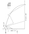
図8においては、バルブ用アクチュエータ本体14に本発明のトルクリミッタを搭載し、動力伝達を遮断した時のボールのリフト量とクラッチ板に加わる作動トルクとの関係を示している。グラフ中、実線は本発明のトルクリミッタ、一点鎖線は特許文献1・2、二点鎖線は特許文献3を示している。先ず、本発明のトルクリミッタの特性を説明する。
Next, the characteristics of the torque limiter of the present invention during power transmission will be compared with those of
FIG. 8 shows the relationship between the lift amount of the ball and the operating torque applied to the clutch plate when the torque limiter of the present invention is mounted on the valve actuator
何らかの理由により、出力軸に過負荷が加わってボールガイド11の回転が停止すると、ボール13が斜面部47を作動トルクT1により移動を開始する。ボール13が斜面部47とアール面部46との境界、すなわち始点Sに差し掛かった位置における作動トルクをT2とすると、ボール13が始点Sを乗り越える際にこの作動トルクT2から作動トルクがやや上昇し、設定トルク(動力伝達を遮断する定格トルク)T3に達する。そして、ボール13が始点Sを乗り越えた後、アール面部46に沿って移動することにより、作動トルクは二次曲線を描きながら緩やかに減少していく。従って、設定トルクT3を超えた後には、ボール13が斜面部47側に押し戻されることがない。このように、ボール13が斜面部47からアール面部46を移動しているため、急激な作動トルクの上昇が防がれている。
For some reason, when an overload is applied to the output shaft and the rotation of the ball guide 11 is stopped, the
また、ボール13がアール面部46を移動するときの移動量が大きくなるため、リフト量が大きくなる。そのため、ボールガイド11とクラッチ板27との離間距離Lが大きくなる。
また、ボール13が斜面部47の移動を開始するときの始動トルクT1と、設定トルクT3との値の差が小さくなっており、ボール13が斜面部47を移動するまでの作動トルクの変化が抑えられる。このため、耐久性も向上している。
Further, since the amount of movement when the
Further, the difference in value between the starting torque T1 when the
一方、同文献1、2のボール1が傾斜部3の移動を開始するときの始動トルクV1は、スプリングの弾発付勢力が小さく設定されていることにより、本発明のトルクリミッタに比較して小さくなっている。
次いで、ボール1が傾斜部3と平面部4の境界すなわち角部5に達すると、設定トルクV2(=T3)に達するが、同文献1、2は、本発明と比較してこの設定トルクV2に達するまでにトルクが急激に上昇することになる。そのため、この急激な作動トルクの増加に予め対応して角部5の形状を調整し、ボール1が角部5を確実に乗り越えるように設定する必要がある。
On the other hand, the starting torque V1 when the
Next, when the
しかも、前述したようにスプリングの弾発付勢力を小さく設定しているものの、ヘルツ応力が上昇しやすい構成であることには変わりがないため、変形や摩耗が生じやすくなっている。更に、角部5が変形・摩耗したときには、この角部5に対してボール1が乗り越え易くなるため、設定トルクV2の値が徐々に小さくなって小さい作動トルクでも頻繁に動力伝達が断たれることになり、正確な動力伝達の遮断ができなくなる。
また、角部5を乗り越えた直後にボール1が平面部4に移動するため、リフト量が本発明と比べて極めて少ない。そのため、リミットスイッチ等による検出も難しくなる。
In addition, as described above, although the spring urging force of the spring is set to be small, the configuration is such that the Hertzian stress is likely to increase, so that deformation and wear are likely to occur. Further, when the corner portion 5 is deformed or worn, the
Further, since the
特許文献3の場合、ボールガイドの回転が停止すると、ボールは始動トルクW1(=V1)により第1傾斜面を移動し、同文献1・2と同様に角部に達したときに設定トルクW2(=T3=V2)に達する。しかし、同文献3は、第1傾斜面に続けて第2傾斜面を設けているので、一旦作動トルクが減少した後に、ボールが第2傾斜面を移動することにより再度作動トルクが急上昇する。この動作により、ボールの移動が不安定になる。
In the case of Patent Document 3, when the rotation of the ball guide is stopped, the ball moves on the first inclined surface by the starting torque W1 (= V1), and the set torque W2 when the ball reaches the corner as in
しかも、ボールが第1傾斜面と第2傾斜面との間で進退を繰り返すおそれのある構造であるため、ボールがこの位置にあるときにトルクが増減して動作が安定し難くなっている。更に、2箇所の角部がそれぞれ変形・摩耗することで耐久性が低くなり、破損しやすくなったり、部品交換を頻繁におこなう必要性も生じる。 In addition, since the ball has a structure that may repeatedly advance and retreat between the first inclined surface and the second inclined surface, the torque is increased or decreased when the ball is in this position, making it difficult to stabilize the operation. In addition, the two corners are deformed and worn, resulting in low durability, and breakage is liable to occur, and parts need to be frequently replaced.
また、第1、第2傾斜面により、ボールのリフト量は長くはなるが、2つの角部に対してボールを乗り越えさせるためにスプリングの弾発付勢力を上げることはできないため、動作を安定させることが難しくなる。 In addition, although the lift amount of the ball is increased by the first and second inclined surfaces, the spring urging force cannot be increased in order to get over the two corners, so the operation is stable. It becomes difficult to let you.
なお、本発明のトルクリミッタは、バルブ用アクチュエータ以外の各種の機器や装置などに利用することもでき、その場合にも、上記と同様の効果を発揮できる。 The torque limiter of the present invention can also be used for various devices and devices other than the valve actuator, and in that case, the same effect as described above can be exhibited.
10 トルクリミッタ本体
11 ボールガイド
13 ボール
14 バルブ用アクチュエータ本体
23 回転軸
27 クラッチ板
44 溝部
45 平面部
46 アール面部
47 斜面部
C 下方頂部
L 離間距離
S 始点
DESCRIPTION OF
Claims (5)
Priority Applications (1)
| Application Number | Priority Date | Filing Date | Title |
|---|---|---|---|
| JP2008186944A JP5317171B2 (en) | 2008-07-18 | 2008-07-18 | Valve actuator with torque limiter |
Applications Claiming Priority (1)
| Application Number | Priority Date | Filing Date | Title |
|---|---|---|---|
| JP2008186944A JP5317171B2 (en) | 2008-07-18 | 2008-07-18 | Valve actuator with torque limiter |
Publications (2)
| Publication Number | Publication Date |
|---|---|
| JP2010025220A true JP2010025220A (en) | 2010-02-04 |
| JP5317171B2 JP5317171B2 (en) | 2013-10-16 |
Family
ID=41731250
Family Applications (1)
| Application Number | Title | Priority Date | Filing Date |
|---|---|---|---|
| JP2008186944A Active JP5317171B2 (en) | 2008-07-18 | 2008-07-18 | Valve actuator with torque limiter |
Country Status (1)
| Country | Link |
|---|---|
| JP (1) | JP5317171B2 (en) |
Cited By (5)
| Publication number | Priority date | Publication date | Assignee | Title |
|---|---|---|---|---|
| CN104455282A (en) * | 2014-11-30 | 2015-03-25 | 重庆泽田汽车部件有限责任公司 | Collision bead type swing arm |
| EP2921047A1 (en) * | 2014-03-21 | 2015-09-23 | Röwer & Rüb GmbH | Guide grating holder for a guide grating of a horse guiding assembly and guide grating with guide grating holder and horse guiding assembly |
| KR101749255B1 (en) * | 2015-09-10 | 2017-07-03 | 훌루테크 주식회사 | Steering apparatus with safety device by the same |
| KR101784751B1 (en) * | 2015-09-10 | 2017-10-12 | 훌루테크 주식회사 | Finding method for locked steering apparatus and navigation method by the same and unlocking process for the locked steering apparatus by the same |
| JP2020508424A (en) * | 2017-02-27 | 2020-03-19 | コンセプト アンド デザイン リミテッド | Apparatus and method for preventing backlash |
Citations (4)
| Publication number | Priority date | Publication date | Assignee | Title |
|---|---|---|---|---|
| JPS6023319U (en) * | 1983-07-22 | 1985-02-18 | 日立工機株式会社 | overload clutch |
| JPS61211533A (en) * | 1985-03-13 | 1986-09-19 | Masao Fukumoto | Torque releaser |
| JPS63254231A (en) * | 1987-04-13 | 1988-10-20 | Tsubakimoto Emason:Kk | Ball clutch |
| JP2004019938A (en) * | 2002-06-20 | 2004-01-22 | Kitz Corp | Actuator for valves |
-
2008
- 2008-07-18 JP JP2008186944A patent/JP5317171B2/en active Active
Patent Citations (4)
| Publication number | Priority date | Publication date | Assignee | Title |
|---|---|---|---|---|
| JPS6023319U (en) * | 1983-07-22 | 1985-02-18 | 日立工機株式会社 | overload clutch |
| JPS61211533A (en) * | 1985-03-13 | 1986-09-19 | Masao Fukumoto | Torque releaser |
| JPS63254231A (en) * | 1987-04-13 | 1988-10-20 | Tsubakimoto Emason:Kk | Ball clutch |
| JP2004019938A (en) * | 2002-06-20 | 2004-01-22 | Kitz Corp | Actuator for valves |
Cited By (6)
| Publication number | Priority date | Publication date | Assignee | Title |
|---|---|---|---|---|
| EP2921047A1 (en) * | 2014-03-21 | 2015-09-23 | Röwer & Rüb GmbH | Guide grating holder for a guide grating of a horse guiding assembly and guide grating with guide grating holder and horse guiding assembly |
| CN104455282A (en) * | 2014-11-30 | 2015-03-25 | 重庆泽田汽车部件有限责任公司 | Collision bead type swing arm |
| KR101749255B1 (en) * | 2015-09-10 | 2017-07-03 | 훌루테크 주식회사 | Steering apparatus with safety device by the same |
| KR101784751B1 (en) * | 2015-09-10 | 2017-10-12 | 훌루테크 주식회사 | Finding method for locked steering apparatus and navigation method by the same and unlocking process for the locked steering apparatus by the same |
| JP2020508424A (en) * | 2017-02-27 | 2020-03-19 | コンセプト アンド デザイン リミテッド | Apparatus and method for preventing backlash |
| JP7162608B2 (en) | 2017-02-27 | 2022-10-28 | コンセプト アンド デザイン リミテッド | Backlash prevention device and method |
Also Published As
| Publication number | Publication date |
|---|---|
| JP5317171B2 (en) | 2013-10-16 |
Similar Documents
| Publication | Publication Date | Title |
|---|---|---|
| JP5317171B2 (en) | Valve actuator with torque limiter | |
| JP5150319B2 (en) | Valve actuator | |
| JP2005224938A (en) | Screwdriver tool | |
| EP3479959A1 (en) | Ratchet wrench | |
| JP2010276166A (en) | Reverse input cutoff clutch, transmission ratio variable mechanism, and steering device for vehicle | |
| US20170234439A1 (en) | Fluid controller | |
| US20100327668A1 (en) | Robot crash protector | |
| JP2006307972A (en) | Direct acting one-way clutch | |
| WO2012127804A1 (en) | Operating device | |
| JP6866863B2 (en) | Limit switch | |
| JP6839968B2 (en) | Limit switch | |
| WO2010007764A1 (en) | Bearing and drive device having same | |
| JPH0619172B2 (en) | Ball joint | |
| JP2007002961A (en) | Mechanical overload protective device | |
| JP2006057688A (en) | Reverse input shutoff device | |
| JP2007010000A (en) | Axial one-way clutch | |
| EP2002149B1 (en) | Device for converting a rotary motion into a linear motion | |
| WO2016013437A1 (en) | Gear device | |
| JP2003194096A (en) | Torque limiter | |
| JP7076786B2 (en) | Gear mechanism with torque limiter | |
| JP4536585B2 (en) | Hollow shaft reducer with overload protection device | |
| JP2018040410A (en) | Bidirectional clutch | |
| WO2019097733A1 (en) | Speed governor for air motor, and air tool | |
| JP6513758B2 (en) | Valve opening adjustment mechanism | |
| JP2022077212A (en) | Centrifugal brake |
Legal Events
| Date | Code | Title | Description |
|---|---|---|---|
| A621 | Written request for application examination |
Free format text: JAPANESE INTERMEDIATE CODE: A621 Effective date: 20110714 |
|
| A977 | Report on retrieval |
Free format text: JAPANESE INTERMEDIATE CODE: A971007 Effective date: 20120518 |
|
| A131 | Notification of reasons for refusal |
Free format text: JAPANESE INTERMEDIATE CODE: A131 Effective date: 20120522 |
|
| A521 | Request for written amendment filed |
Free format text: JAPANESE INTERMEDIATE CODE: A523 Effective date: 20120723 |
|
| A131 | Notification of reasons for refusal |
Free format text: JAPANESE INTERMEDIATE CODE: A131 Effective date: 20130122 |
|
| A521 | Request for written amendment filed |
Free format text: JAPANESE INTERMEDIATE CODE: A523 Effective date: 20130325 |
|
| TRDD | Decision of grant or rejection written | ||
| A01 | Written decision to grant a patent or to grant a registration (utility model) |
Free format text: JAPANESE INTERMEDIATE CODE: A01 Effective date: 20130625 |
|
| A61 | First payment of annual fees (during grant procedure) |
Free format text: JAPANESE INTERMEDIATE CODE: A61 Effective date: 20130704 |
|
| R150 | Certificate of patent or registration of utility model |
Ref document number: 5317171 Country of ref document: JP Free format text: JAPANESE INTERMEDIATE CODE: R150 Free format text: JAPANESE INTERMEDIATE CODE: R150 |
|
| R250 | Receipt of annual fees |
Free format text: JAPANESE INTERMEDIATE CODE: R250 |
|
| R250 | Receipt of annual fees |
Free format text: JAPANESE INTERMEDIATE CODE: R250 |
|
| R250 | Receipt of annual fees |
Free format text: JAPANESE INTERMEDIATE CODE: R250 |
|
| R250 | Receipt of annual fees |
Free format text: JAPANESE INTERMEDIATE CODE: R250 |
|
| R250 | Receipt of annual fees |
Free format text: JAPANESE INTERMEDIATE CODE: R250 |
|
| R250 | Receipt of annual fees |
Free format text: JAPANESE INTERMEDIATE CODE: R250 |
|
| R250 | Receipt of annual fees |
Free format text: JAPANESE INTERMEDIATE CODE: R250 |
|
| R250 | Receipt of annual fees |
Free format text: JAPANESE INTERMEDIATE CODE: R250 |