JP2010025203A - Crown type retainer - Google Patents
Crown type retainer Download PDFInfo
- Publication number
- JP2010025203A JP2010025203A JP2008186287A JP2008186287A JP2010025203A JP 2010025203 A JP2010025203 A JP 2010025203A JP 2008186287 A JP2008186287 A JP 2008186287A JP 2008186287 A JP2008186287 A JP 2008186287A JP 2010025203 A JP2010025203 A JP 2010025203A
- Authority
- JP
- Japan
- Prior art keywords
- pitch circle
- ball
- cage
- portions
- Prior art date
- Legal status (The legal status is an assumption and is not a legal conclusion. Google has not performed a legal analysis and makes no representation as to the accuracy of the status listed.)
- Granted
Links
Images


Classifications
-
- F—MECHANICAL ENGINEERING; LIGHTING; HEATING; WEAPONS; BLASTING
- F16—ENGINEERING ELEMENTS AND UNITS; GENERAL MEASURES FOR PRODUCING AND MAINTAINING EFFECTIVE FUNCTIONING OF MACHINES OR INSTALLATIONS; THERMAL INSULATION IN GENERAL
- F16C—SHAFTS; FLEXIBLE SHAFTS; ELEMENTS OR CRANKSHAFT MECHANISMS; ROTARY BODIES OTHER THAN GEARING ELEMENTS; BEARINGS
- F16C33/00—Parts of bearings; Special methods for making bearings or parts thereof
- F16C33/30—Parts of ball or roller bearings
- F16C33/66—Special parts or details in view of lubrication
- F16C33/6637—Special parts or details in view of lubrication with liquid lubricant
- F16C33/6681—Details of distribution or circulation inside the bearing, e.g. grooves on the cage or passages in the rolling elements
-
- F—MECHANICAL ENGINEERING; LIGHTING; HEATING; WEAPONS; BLASTING
- F16—ENGINEERING ELEMENTS AND UNITS; GENERAL MEASURES FOR PRODUCING AND MAINTAINING EFFECTIVE FUNCTIONING OF MACHINES OR INSTALLATIONS; THERMAL INSULATION IN GENERAL
- F16C—SHAFTS; FLEXIBLE SHAFTS; ELEMENTS OR CRANKSHAFT MECHANISMS; ROTARY BODIES OTHER THAN GEARING ELEMENTS; BEARINGS
- F16C33/00—Parts of bearings; Special methods for making bearings or parts thereof
- F16C33/30—Parts of ball or roller bearings
- F16C33/38—Ball cages
- F16C33/41—Ball cages comb-shaped
- F16C33/412—Massive or moulded comb cages, e.g. snap ball cages
- F16C33/414—Massive or moulded comb cages, e.g. snap ball cages formed as one-piece cages, i.e. monoblock comb cages
- F16C33/416—Massive or moulded comb cages, e.g. snap ball cages formed as one-piece cages, i.e. monoblock comb cages made from plastic, e.g. injection moulded comb cages
-
- F—MECHANICAL ENGINEERING; LIGHTING; HEATING; WEAPONS; BLASTING
- F16—ENGINEERING ELEMENTS AND UNITS; GENERAL MEASURES FOR PRODUCING AND MAINTAINING EFFECTIVE FUNCTIONING OF MACHINES OR INSTALLATIONS; THERMAL INSULATION IN GENERAL
- F16C—SHAFTS; FLEXIBLE SHAFTS; ELEMENTS OR CRANKSHAFT MECHANISMS; ROTARY BODIES OTHER THAN GEARING ELEMENTS; BEARINGS
- F16C19/00—Bearings with rolling contact, for exclusively rotary movement
- F16C19/02—Bearings with rolling contact, for exclusively rotary movement with bearing balls essentially of the same size in one or more circular rows
- F16C19/04—Bearings with rolling contact, for exclusively rotary movement with bearing balls essentially of the same size in one or more circular rows for radial load mainly
- F16C19/06—Bearings with rolling contact, for exclusively rotary movement with bearing balls essentially of the same size in one or more circular rows for radial load mainly with a single row or balls
Landscapes
- Engineering & Computer Science (AREA)
- General Engineering & Computer Science (AREA)
- Mechanical Engineering (AREA)
- Rolling Contact Bearings (AREA)
Abstract
Description
本発明は、玉軸受用の冠型保持器に関する。 The present invention relates to a crown type cage for ball bearings.
一般的な玉軸受として、外輪と、内輪と、外輪軌道面および内輪軌道面を転動する複数の玉と、これら複数の玉を転動自在として保持している合成樹脂製の冠型保持器(以下、保持器ともいう)とを備えたものがある。図6(a)は、従来の保持器40の一部を示した斜視図であり、図6(b)は、玉軸受内に取り付けられた状態にある従来の保持器40の断面図である。図6(a)において、この保持器40には、複数の玉41を転動自在に保持するために、ポケット42が周方向に等間隔で複数形成されている。ポケット42は軸方向一方側(図6(a)では上方側)に開口して形成されている。また、ポケット42が形成されている部分には、対向する一対の爪部43が設けられており、これら一対の爪部43によってポケット42内に配置した玉41が抜け出ることを防止している。
As general ball bearings, outer ring, inner ring, outer ring raceway surface and a plurality of balls rolling on the inner ring raceway surface, and a synthetic resin crown-type cage that holds the plurality of balls as rollable (Hereinafter also referred to as a cage). FIG. 6A is a perspective view showing a part of a
玉軸受が回転すると、これに伴って保持器40も回転し、保持器40に遠心力が作用する。特に玉軸受の回転数が高く(例えば内径30mmの玉軸受で3万rpm)、高温(例えば100℃)の環境で使用される場合、例えば、エンジンの補機用として使用される場合、保持器40は合成樹脂製であって、保持器40の爪部43側は、環状となっている基部46に比べて剛性が低い形状となっているため、前記遠心力により、図6(b)の破線で示しているように、爪部43側は径方向外方(外輪49側)へ変形する。これに対し玉41は玉軸受内でピッチ円上に配置されたままであることから、前記変形によって、両側の爪部43それぞれの内周部44は玉41に接近しさらにその先端部が局部的に接触し、両側の内周部44によって、玉41に形成されている油膜(潤滑油)が掻き取られるおそれがある。このため玉41表面の潤滑油が不足し、玉軸受における潤滑状態が悪化し、玉軸受が焼き付くおそれがある。
そこで、特許文献1に示しているように、ポケットの開口側に環状の補強部材が取り付けられている保持器がある。
When the ball bearing rotates, the
Therefore, as shown in Patent Document 1, there is a cage in which an annular reinforcing member is attached to the opening side of the pocket.
特許文献1に記載の保持器によれば、遠心力に基づく保持器の変形を補強部材が抑え、保持器の一部が玉に局部的に接触するのを防止し、玉の潤滑油が掻き取られるのを防ぐことができる。しかし、補強部材が別途必要となっているため、保持器の部品点数が増加し、コスト高になるという問題点がある。 According to the cage described in Patent Document 1, the reinforcing member suppresses deformation of the cage due to centrifugal force, prevents a part of the cage from contacting the ball locally, and the lubricating oil of the ball scrapes. Can be prevented from being taken. However, since a reinforcing member is required separately, there is a problem that the number of parts of the cage increases and the cost increases.
そこで、本発明は、剛性を高めるための別部材を取り付けなくても、遠心力に基づく変形によって玉に局部的に接触することを防止できる冠型保持器を提供することを目的とする。 Therefore, an object of the present invention is to provide a crown type cage that can prevent local contact with a ball due to deformation based on centrifugal force without attaching a separate member for increasing rigidity.
前記目的を達成するための本発明の冠型保持器は、軸方向一方側に開口し、ピッチ円上に設けられた複数の玉を転動自在に保持するポケットが周方向に複数形成された玉軸受用の冠型保持器において、前記ポケットそれぞれは、当該ポケットの底となる底球面部と、この底球面部から開口側に相互が対向して形成されている一対の対向球面部と、を有し、前記ポケットそれぞれにおける前記一対の対向球面部の内の一方は、前記ピッチ円に対して径方向内寄りに形成され、前記一対の対向球面部の内の他方は、前記ピッチ円に対して径方向外寄りに形成され、遠心力によって変形した際に、前記他方の対向球面部の内周部が前記玉と非接触となるように当該他方の対向球面部側の保持器内周面から前記ピッチ円までの距離が設定されている。 In order to achieve the above object, the crown type cage of the present invention has an opening on one side in the axial direction, and a plurality of pockets are formed in the circumferential direction to hold a plurality of balls provided on the pitch circle in a freely rolling manner. In the crown type cage for ball bearings, each of the pockets includes a bottom spherical surface portion serving as a bottom of the pocket, and a pair of opposed spherical surface portions formed to face each other from the bottom spherical surface portion to the opening side, One of the pair of opposed spherical portions in each of the pockets is formed radially inward with respect to the pitch circle, and the other of the pair of opposed spherical portions is formed on the pitch circle. On the other hand, the inner circumferential surface of the other opposing spherical surface side is formed so that the inner circumferential portion of the other opposing spherical surface portion is in non-contact with the ball when deformed by centrifugal force. A distance from the surface to the pitch circle is set.
本発明によれば、玉軸受が回転すると冠型保持器も回転し、遠心力によって冠型保持器が拡径するように変形する。これにより、玉のピッチ円に対して径方向内寄りに形成された一方の対向球面部の内周部は、玉に近づくように変位するが、ピッチ円に対して径方向外寄りに形成された他方の対向球面部の外周部は、玉から離れる方向に変位するので、対向する対向球面部の間隔が狭くなることを抑制することができる。そして、遠心力によって冠型保持器が変形した際に、他方の対向球面部の内周部は玉と非接触となる。このため、従来のように剛性を高めるための補強部材を別途設けなくても、冠型保持器の一部が玉に局部的に接触するのを防止することができ、当該接触による発熱、摩耗を防ぐことができる。 According to the present invention, when the ball bearing rotates, the crown-shaped cage also rotates, and the crown-shaped cage is deformed so as to expand its diameter by centrifugal force. As a result, the inner peripheral portion of one opposing spherical portion formed radially inward with respect to the pitch circle of the ball is displaced so as to approach the ball, but is formed radially outward with respect to the pitch circle. Since the outer peripheral portion of the other opposing spherical surface portion is displaced in the direction away from the ball, it is possible to suppress the interval between the opposing opposing spherical portions from being narrowed. When the crown type cage is deformed by the centrifugal force, the inner peripheral portion of the other opposing spherical portion is not in contact with the ball. For this reason, it is possible to prevent a part of the crown-type cage from contacting the ball locally without separately providing a reinforcing member for increasing the rigidity as in the prior art. Can be prevented.
本発明によれば、ポケットの対向する対向球面部の間隔が狭くなることを抑制することができるので、冠型保持器の一部が玉に局部的に接触するのを防止することができ、当該接触による発熱、摩耗を防ぐことができる。この結果、従来のように冠型保持器の部品点数が増加しコスト高となってしまうのを防止することができる。 According to the present invention, since it is possible to suppress the interval between the opposing spherical portions of the pockets from becoming narrow, it is possible to prevent a part of the crown-shaped cage from contacting the ball locally, Heat generation and wear due to the contact can be prevented. As a result, it is possible to prevent the number of parts of the crown-type cage from increasing and increasing the cost as in the prior art.
以下、本発明の実施の形態を図面に基づいて説明する。
図1は本発明の冠型保持器が取り付けられた状態にある玉軸受の断面図である。この玉軸受は、外輪1と、この外輪1と同心上に設けられている内輪2と、外輪1および内輪2の間に設けられた複数の玉3と、これら複数の玉3を等間隔で保持する冠型保持器4(以下、保持器4という)とを備えている。
外輪1の内周面に外輪軌道面11が形成されており、内輪2の外周面に内輪軌道面12が形成されている。複数の玉3それぞれの中心は、玉軸受の軸心Cを中心とする一つのピッチ円P上に配置されており、これらの玉3は、外輪軌道面11および内輪軌道面12を転動する。そして、保持器4は、ピッチ円P上にあるこれら複数の玉3を転動自在として保持している。なお、玉3は全て同じものである。
Hereinafter, embodiments of the present invention will be described with reference to the drawings.
FIG. 1 is a cross-sectional view of a ball bearing in a state where a crown type cage of the present invention is attached. The ball bearing includes an outer ring 1, an
An outer ring raceway surface 11 is formed on the inner peripheral surface of the outer ring 1, and an inner
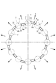
図2は保持器4の斜視図である。図1および図2に示しているように、保持器4には、複数(図例では10個)の前記玉3を転動自在に保持するポケット7が周方向に複数(図例では10個)形成されており、ポケット7は、軸方向の一方側(図1および図2では左側)に開口している。保持器4の全体形状は環状となっていて、いわゆる冠型として構成されている。また、保持器4は合成樹脂製である。複数の玉3それぞれを、ポケット7内に押し入れる際に、玉3によってポケット7の開口端18a,18bの間が弾性的に押し広げられる。
FIG. 2 is a perspective view of the cage 4. As shown in FIGS. 1 and 2, the retainer 4 has a plurality of pockets 7 (10 in the illustrated example) for holding the
保持器4は、円環状の基部6と本体部8とを有している。本体部8は、ポケット7が形成されている部分であり、基部6は、外輪1と内輪2との間に設けられている複数の玉3よりも軸方向の他方側(図1および図2では右側)に配置されている部分である。本体部8は、柱部14を周方向に複数有していて、各柱部14は環状の基部6から軸方向の一方側(図2では左側)へ突出している。そして、周方向に隣り合う柱部14間が前記ポケット7となる。柱部14それぞれの軸方向の一方側には、一対の爪部17a,17a(17b,17b)が当該一方側へさらに突出して設けられている。そして、ポケット7を挟んで対向する爪部17a,17bが、当該ポケット7内に配置した玉3が抜け出ることを防止する。爪部17a,17bの内面側の先端がポケット開口端18a,18bとなる。
The cage 4 has an
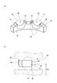
図3は、ポケット7およびその周辺部の説明図である。ポケット7それぞれは、当該ポケット7の底となる底球面部21と、この底球面部21から開口側へ延びるようにして形成されている一対の対向球面部22,23とを有している。一対の対向球面部22,23は、相互が対向するように形成されている。底球面部21および対向球面部22,23によって、一つのポケット内面9が構成されていて、ポケット内面9は、一点C0を中心とし、玉3の曲率半径r1よりも若干大きな曲率半径r2を有する球面に沿った形状である。つまり、一対の対向球面部22,23及び底球面部21は、互いに同心の球面を形成している。保持器4が回転していない状態で、ポケット7の前記一点(ポケット7の中心点)C0は、ピッチ円P上に配設されポケット7aに転動自在として収容させた玉3の中心点と一致する。
FIG. 3 is an explanatory diagram of the
なお、ポケット内面9の内の前記底球面部21は、保持器4を軸方向から見て(図3では上から下へ見て)ポケット開口端18a,18b間に見える範囲であり、残りの両側部分それぞれが対向球面部22,23である。つまり、図3において、点m1と点m2間が底球面部21であり、点m1からポケット開口端18aまでが一方の対向球面部22であり、点m2からポケット開口端18bまでが他方の対向球面部23である。
The bottom
図4は玉3および保持器4を軸方向から見た説明図であり、図5(a)は図4の一部を拡大して説明する説明図である。なお、図4は、図3の矢印IVにおける断面図(点C0を含む断面)である。ポケット7それぞれにおける前記対向球面部22,23の内の一方(図5(a)の左側の対向球面部22)は、玉3のピッチ円Pに対して径方向内寄りに形成されていて、前記対向球面部22,23の内の他方(図5(a)の右側の対向球面部23)は、玉3のピッチ円Pに対して径方向外寄りに形成されている。
FIG. 4 is an explanatory view of the
この保持器4の内の、一方の前記対向球面部22が形成されている部分(第一の柱部14a)に関して、玉3のピッチ円Pから当該部分の外周面31までの距離a1は、ピッチ円Pから当該部分の内周面32までの距離a2よりも小さく設定されている(a1<a2)。これに対し、他方の前記対向球面部23が形成されている部分(第二の柱部14b)に関して、玉3のピッチ円Pから当該部分の外周面33までの距離b1は、ピッチ円Pから当該部分の内周面34までの距離b2よりも大きく設定されている(b1>b2)。そして、距離b2<距離a2となるように設定されている。なお、第一の柱部14aと第二の柱部14bとの厚さ(径方向寸法)は同じである。この構成により、一方の対向球面部22が、玉3のピッチ円Pに対して径方向内寄りに形成され、他方の対向球面部23が、玉3のピッチ円Pに対して径方向外寄りに形成される。このように構成した保持器4によれば、一方の対向球面部22と玉3との接触部(接触点)と、他方の対向球面部23と当該玉3との接触部(接触点)とを、玉3のピッチ円Pに対して径方向内側と径方向外側とに異ならせて配置することができる。
Regarding the portion (
また、前記のとおり距離a1<距離a2かつ距離b1>距離b2とするにあたり、第一の柱部14aの外周面31をピッチ円Pよりも径方向外側とし、第二の柱部14bの内周面34をピッチ円Pよりも径方向内側(a1>0、b2>0)とし、距離b2<距離a2となるように設定されているが、外周面31と内周面34との内の一方又は双方をピッチ円Pと一致させてもよい(a1=0、b2=0)。このように、第二柱部14bの内周面34からピッチ円Pまでの距離b2は(距離a2よりも)小さくなるように設定されている。このように構成することで、保持器4が遠心力によって変形した際に、対向球面部23の内周部23a(爪部17bの内周側端部)が玉3と非接触となるように構成することができる。例えば距離b2=0と設定すれば内周部23aが玉3と接触することはない。
Further, as described above, when the distance a1 <the distance a2 and the distance b1> the distance b2, the outer
なお、図5(b)は従来の保持器40を説明している説明図であり、本発明に係る図5(a)と対比するための図である。従来の保持器40では、一方の対向球面部47が形成されている部分50a、および、当該対向球面部47に対向する他方の対向球面部48が形成されている部分50bの双方に関して、玉41のピッチ円Pから外周面40aまでの距離d1と、当該ピッチ円Pから保持器40の内周面40bまでの距離d2とは、同じであり(d1=d2)、対向している一対の対向球面部47,48は、玉41のピッチ円Pに対して径方向で同じ位置に形成されている。
FIG. 5B is an explanatory diagram for explaining a
この従来の保持器40の場合、玉軸受が回転すると、これに伴って保持器40も回転し、保持器40には遠心力が作用し拡径するように変形する。この際、玉41はピッチ円P上に配置されたままであるため、前記のとおり、保持器40の内のピッチ円Pよりも内周部(図6(b)の爪部43の内の内周部)44は、玉41に近づくように変位する。これにより、ポケット42両側の内周部44が玉41に接近しさらに接触し、玉41に形成されている油膜(潤滑油)が掻き取られるおそれがある。この場合、玉軸受における潤滑状態が悪化し、玉軸受が焼き付くおそれがある。
In the case of the
しかし、本発明によれば、玉軸受が回転すると保持器4も回転し、保持器4には遠心力が作用する(図4の矢印R参照)。この際、図5(a)において、玉3のピッチ円Pに対して径方向内寄りに形成された一方の対向球面部22の内周部22aは、玉3に近づくように変位するが、ピッチ円Pに対して径方向外寄りに形成された他方の対向球面部23の外周部23bは、玉3から離れる方向に変位するので、対向する対向球面部22,23の間隔(ポケット7の玉3の収納空間)が狭くなることを抑制することができる。すなわち、本発明の構成によれば、ポケット内面9の直径D(図5(a)参照)が、遠心力による変形前後で変化することを抑えることができる。
However, according to the present invention, when the ball bearing rotates, the cage 4 also rotates, and centrifugal force acts on the cage 4 (see arrow R in FIG. 4). At this time, in FIG. 5A, the inner
このため、対向球面部22の内周部22aが玉3に局部的に接触することを防止でき、玉3に形成されている油膜が掻き取られるのを防ぐことができる。したがって、玉軸受が高速で回転(例えば内径30mmの玉軸受で3万rpm)し、高温(例えば100℃)の環境で使用される場合であっても、従来のように玉軸受における潤滑状態が悪化することを防止することができ、保持器4が局部的に摩耗したり玉軸受が焼き付いたりするのを防ぐことができる。
For this reason, it can prevent that the inner
また、図4に示しているように、玉3のピッチ円Pに対して径方向内寄りに形成された対向球面部22を両側部に有する柱部14aと、ピッチ円Pに対して径方向外寄りに形成された対向球面部23を両側部に有する柱部14bとは、周方向に交互に設けられている。すなわち、径方向内寄りに形成された対向球面部22を有する柱部14aと、径方向外寄りに形成された対向球面部23を有する柱部14bとは、ピッチ円Pを中心として内径側と外径側とに交互に配設されている。
Further, as shown in FIG. 4,
また、本発明の冠型保持器は、図示する形態に限らず本発明の範囲内において他の形態のものであっても良い。本発明では、一方の対向球面部22の内の少なくとも爪部17aの内面が、ピッチ円Pに対して径方向内寄りに形成されていて、他方の対向球面部23の内の少なくとも爪部17bの内面が、ピッチ円Pに対して径方向外寄りに形成されていて、遠心力によって変形した場合に、爪部17bの先端において、前記他方の対向球面部23の内周部23aが玉3と非接触となるようにピッチ円Pから保持器内周面34までの距離b2が小さく設定されていればよい。
Further, the crown type cage of the present invention is not limited to the illustrated form, but may be of other forms within the scope of the present invention. In the present invention, at least the inner surface of the
3 玉
4 冠形保持器
7 ポケット
21 底球面部
22 対向球面部
23 対向球面部
b2 保持器内周面からピッチ円までの距離
P ピッチ円
3 Ball 4 Crown-shaped
Claims (1)
前記ポケットそれぞれは、当該ポケットの底となる底球面部と、この底球面部から開口側に相互が対向して形成されている一対の対向球面部と、を有し、
前記ポケットそれぞれにおける前記一対の対向球面部の内の一方は、前記ピッチ円に対して径方向内寄りに形成され、前記一対の対向球面部の内の他方は、前記ピッチ円に対して径方向外寄りに形成され、
遠心力によって変形した際に、前記他方の対向球面部の内周部が前記玉と非接触となるように当該他方の対向球面部側の保持器内周面から前記ピッチ円までの距離が設定されていることを特徴とする冠型保持器。 In the crown type cage for ball bearings, which is open on one side in the axial direction and has a plurality of pockets formed in the circumferential direction to hold a plurality of balls provided on the pitch circle in a freely rolling manner.
Each of the pockets has a bottom spherical surface portion serving as a bottom of the pocket, and a pair of opposed spherical surface portions formed so as to face each other from the bottom spherical surface portion to the opening side,
One of the pair of opposed spherical portions in each of the pockets is formed radially inward with respect to the pitch circle, and the other of the pair of opposed spherical portions is radial with respect to the pitch circle. Formed outside,
The distance from the inner peripheral surface of the other opposing spherical surface side to the pitch circle is set so that the inner peripheral portion of the other opposing spherical surface portion is not in contact with the ball when deformed by centrifugal force. A crown-type cage characterized by being made.
Priority Applications (1)
| Application Number | Priority Date | Filing Date | Title |
|---|---|---|---|
| JP2008186287A JP5131068B2 (en) | 2008-07-17 | 2008-07-17 | Crown type cage |
Applications Claiming Priority (1)
| Application Number | Priority Date | Filing Date | Title |
|---|---|---|---|
| JP2008186287A JP5131068B2 (en) | 2008-07-17 | 2008-07-17 | Crown type cage |
Publications (2)
| Publication Number | Publication Date |
|---|---|
| JP2010025203A true JP2010025203A (en) | 2010-02-04 |
| JP5131068B2 JP5131068B2 (en) | 2013-01-30 |
Family
ID=41731236
Family Applications (1)
| Application Number | Title | Priority Date | Filing Date |
|---|---|---|---|
| JP2008186287A Expired - Fee Related JP5131068B2 (en) | 2008-07-17 | 2008-07-17 | Crown type cage |
Country Status (1)
| Country | Link |
|---|---|
| JP (1) | JP5131068B2 (en) |
Citations (5)
| Publication number | Priority date | Publication date | Assignee | Title |
|---|---|---|---|---|
| JPH0434512U (en) * | 1990-07-19 | 1992-03-23 | ||
| JP2002081450A (en) * | 2000-09-07 | 2002-03-22 | Ntn Corp | Rotation-directional ball bearing |
| JP2003214436A (en) * | 2002-01-21 | 2003-07-30 | Koyo Seiko Co Ltd | Holder for ball bearing and ball bearing |
| JP2003214437A (en) * | 2002-01-18 | 2003-07-30 | Koyo Seiko Co Ltd | Ball bearing |
| JP2008051294A (en) * | 2006-08-28 | 2008-03-06 | Jtekt Corp | Crown type cage |
-
2008
- 2008-07-17 JP JP2008186287A patent/JP5131068B2/en not_active Expired - Fee Related
Patent Citations (5)
| Publication number | Priority date | Publication date | Assignee | Title |
|---|---|---|---|---|
| JPH0434512U (en) * | 1990-07-19 | 1992-03-23 | ||
| JP2002081450A (en) * | 2000-09-07 | 2002-03-22 | Ntn Corp | Rotation-directional ball bearing |
| JP2003214437A (en) * | 2002-01-18 | 2003-07-30 | Koyo Seiko Co Ltd | Ball bearing |
| JP2003214436A (en) * | 2002-01-21 | 2003-07-30 | Koyo Seiko Co Ltd | Holder for ball bearing and ball bearing |
| JP2008051294A (en) * | 2006-08-28 | 2008-03-06 | Jtekt Corp | Crown type cage |
Also Published As
| Publication number | Publication date |
|---|---|
| JP5131068B2 (en) | 2013-01-30 |
Similar Documents
| Publication | Publication Date | Title |
|---|---|---|
| JP2009536998A (en) | Cage and rolling bearing assembly for ball bearing | |
| JP6717028B2 (en) | Ball bearing | |
| JP6946697B2 (en) | Rolling bearing | |
| JP2016180417A (en) | Conical roller bearing | |
| JP5978578B2 (en) | Ball bearings and cages for ball bearings | |
| JP4946881B2 (en) | Rolling bearing | |
| JP2010025199A (en) | Crown type retainer | |
| JP2007078078A (en) | Retainer for rolling ball bearing and its manufacturing method | |
| JP2008267400A (en) | Ball bearing | |
| JP5272737B2 (en) | Crown type cage and ball bearing | |
| JP5131068B2 (en) | Crown type cage | |
| JP2006207684A (en) | Rolling bearing | |
| JP2009275799A (en) | Deep groove ball bearing | |
| JP5764959B2 (en) | Ball bearing | |
| JP2006017180A (en) | Crown retainer made of synthetic resin | |
| JP2006200615A (en) | Rolling bearing crowned cage | |
| WO2010137434A1 (en) | Ball bearing retainer and ball bearing | |
| JP2005273799A (en) | Roller bearing and pivot bearing device for swing arm | |
| JP2008045572A (en) | Ball bearing cage and ball bearing | |
| JP2009275759A (en) | Deep groove ball bearing | |
| JP2017057876A (en) | Rolling bearing | |
| JP2023006671A (en) | Conical roller bearing | |
| JP6003022B2 (en) | Roller bearing cage | |
| JP2006009988A (en) | Synthetic resin-made snap cage | |
| JP6094637B2 (en) | Roller bearing cage |
Legal Events
| Date | Code | Title | Description |
|---|---|---|---|
| A621 | Written request for application examination |
Free format text: JAPANESE INTERMEDIATE CODE: A621 Effective date: 20110624 |
|
| A521 | Written amendment |
Free format text: JAPANESE INTERMEDIATE CODE: A523 Effective date: 20120423 |
|
| A977 | Report on retrieval |
Free format text: JAPANESE INTERMEDIATE CODE: A971007 Effective date: 20120920 |
|
| TRDD | Decision of grant or rejection written | ||
| A01 | Written decision to grant a patent or to grant a registration (utility model) |
Free format text: JAPANESE INTERMEDIATE CODE: A01 Effective date: 20121009 |
|
| A01 | Written decision to grant a patent or to grant a registration (utility model) |
Free format text: JAPANESE INTERMEDIATE CODE: A01 |
|
| A61 | First payment of annual fees (during grant procedure) |
Free format text: JAPANESE INTERMEDIATE CODE: A61 Effective date: 20121022 |
|
| FPAY | Renewal fee payment (event date is renewal date of database) |
Free format text: PAYMENT UNTIL: 20151116 Year of fee payment: 3 |
|
| R150 | Certificate of patent or registration of utility model |
Free format text: JAPANESE INTERMEDIATE CODE: R150 |
|
| LAPS | Cancellation because of no payment of annual fees |