JP2010024921A - Spark ignition type direct injection engine - Google Patents
Spark ignition type direct injection engine Download PDFInfo
- Publication number
- JP2010024921A JP2010024921A JP2008186155A JP2008186155A JP2010024921A JP 2010024921 A JP2010024921 A JP 2010024921A JP 2008186155 A JP2008186155 A JP 2008186155A JP 2008186155 A JP2008186155 A JP 2008186155A JP 2010024921 A JP2010024921 A JP 2010024921A
- Authority
- JP
- Japan
- Prior art keywords
- spray
- cavity
- injection
- engine
- injector
- Prior art date
- Legal status (The legal status is an assumption and is not a legal conclusion. Google has not performed a legal analysis and makes no representation as to the accuracy of the status listed.)
- Granted
Links
Images


Classifications
-
- Y—GENERAL TAGGING OF NEW TECHNOLOGICAL DEVELOPMENTS; GENERAL TAGGING OF CROSS-SECTIONAL TECHNOLOGIES SPANNING OVER SEVERAL SECTIONS OF THE IPC; TECHNICAL SUBJECTS COVERED BY FORMER USPC CROSS-REFERENCE ART COLLECTIONS [XRACs] AND DIGESTS
- Y02—TECHNOLOGIES OR APPLICATIONS FOR MITIGATION OR ADAPTATION AGAINST CLIMATE CHANGE
- Y02T—CLIMATE CHANGE MITIGATION TECHNOLOGIES RELATED TO TRANSPORTATION
- Y02T10/00—Road transport of goods or passengers
- Y02T10/10—Internal combustion engine [ICE] based vehicles
- Y02T10/12—Improving ICE efficiencies
Landscapes
- Combustion Methods Of Internal-Combustion Engines (AREA)
- Electrical Control Of Air Or Fuel Supplied To Internal-Combustion Engine (AREA)
- Combined Controls Of Internal Combustion Engines (AREA)
Abstract
Description
この発明は、火花点火式直噴エンジンに関し、特に、エンジン冷間時における触媒活性化促進を図る火花点火式直噴エンジンに関する。 The present invention relates to a spark ignition direct injection engine, and more particularly to a spark ignition direct injection engine that promotes catalyst activation when the engine is cold.
従来より、燃費向上を図る等のため、燃料を直接筒内に噴射する直噴エンジンが採用されている。こうした直噴エンジンによると、圧縮比を高くでき、エンジン効率を高めることができる。また、吸入吸気量に関わらず燃料噴射量を自由に調整できる。 2. Description of the Related Art Conventionally, a direct injection engine that directly injects fuel into a cylinder has been adopted in order to improve fuel efficiency. According to such a direct injection engine, the compression ratio can be increased and the engine efficiency can be increased. Further, the fuel injection amount can be freely adjusted regardless of the intake air intake amount.
一方で、近年では、排気ガスのエミッション規制も強化されており、触媒の早期活性化を図ることも求められている。こうした触媒の早期活性化のためには、排気ガス温度を早期に昇温させることが必要であり、点火タイミングをできるだけ遅角することで、排気ガス温度を高めることが考えられる。 On the other hand, in recent years, exhaust gas emission regulations have been strengthened, and it is required to activate the catalyst at an early stage. In order to activate such a catalyst early, it is necessary to raise the exhaust gas temperature as early as possible, and it is conceivable to raise the exhaust gas temperature by retarding the ignition timing as much as possible.
しかし、点火タイミングを大幅に遅角させると、燃焼安定性が悪化してしまうため、この燃焼安定化を確保した上で、点火タイミングを遅角する技術が求められていた。 However, if the ignition timing is significantly retarded, the combustion stability deteriorates. Therefore, a technique for retarding the ignition timing while ensuring this combustion stabilization has been demanded.
そこで、下記特許文献1では、燃料噴射を、上死点を跨ぐタイミングで行なう主噴射と、吸気行程等のタイミングで行なう早期噴射の、前後二回に分けて行い、点火タイミングを上死点よりも大幅に遅角して、燃焼を行なわせるエンジン装置が提案されている。
Therefore, in the following
このように、燃料噴射を予め吸気行程等のタイミングで行うことで、噴射された燃料を、主噴射の噴射前に筒内に拡散させておけるため、主噴射の噴霧に点火されて、燃焼が開始したときには、筒内全体に相対的に緩慢な燃焼を生じさせることができ、燃焼を安定的に生じさせることができるのである。 In this way, by performing fuel injection in advance at the timing of the intake stroke or the like, the injected fuel can be diffused into the cylinder before the main injection, so that the main injection spray is ignited and combustion is performed. When started, relatively slow combustion can be generated in the entire cylinder, and combustion can be stably generated.
すなわち、筒内の状態を、点火プラグ周りに濃い混合気を位置させてその周囲には空気だけとする、いわゆる「成層状態」から、その周囲にも薄い混合気を位置させる、いわゆる「弱成層状態」にすることで、エンジンの燃焼状態を安定させるのである。 That is, the in-cylinder state is a so-called “weak stratification” in which a thick air-fuel mixture is placed around the spark plug and only air is present around the spark plug, so that a thin air-fuel mixture is located around the so-called “stratification state”. By setting the “state”, the combustion state of the engine is stabilized.
なお、この特許文献1にも記載されているように、燃料を噴射するインジェクタは、マルチホール型インジェクタを用いることが考えられる。
As described in
また、特許文献2には、エンジン冠面の凹部を、点火プラグの点火点を中心とした球曲面に形成したものが開示されている。このように凹部を球曲面にすることで、燃焼室を略球面形状とすることができ、常に均一かつ良好な燃焼状態を維持することができる。
ところで、燃費向上を図るためには、エンジン効率を高めるため、圧縮比を高めることが行われる。この圧縮比を高める方法としては、ピストン冠面に、燃焼室のペントルーフ形状に沿うような、ペントルーフ形状の斜面を有する隆起部を設けることが考えられる。 By the way, in order to improve the fuel efficiency, the compression ratio is increased in order to increase the engine efficiency. As a method of increasing the compression ratio, it is conceivable to provide a raised portion having a pent roof-shaped slope along the pent roof shape of the combustion chamber on the piston crown surface.
もっとも、特許文献1のエンジン装置のようにエンジン冷間時の触媒の早期活性化を考慮すると、点火タイミングの時期に、点火プラグ周りに濃い混合気を滞留させる必要があるため、この隆起部の点火プラグに対応する位置に、特許文献2と同様に、凹状のキャビティを形成することで、このキャビティを燃焼空間とすることが考えられる。
However, considering the early activation of the catalyst when the engine is cold as in the engine device of
ここで、特許文献1のエンジン装置においては、燃料の主噴射を点火プラグに向かって噴射するように構成しているが、噴霧タイミングの時期から点火タイミングまでの時間が少しでもズレると、着火性が悪化して、安定した燃焼状態を得られないおそれがある。
Here, in the engine device of
そこで、凹状のキャビティに向かって燃料を噴射して、キャビティ内に噴霧を滞留させることで、長期間、点火プラグ周りに噴霧(濃い混合気)を位置させることが考えられる。 Therefore, it is conceivable that the spray (dense mixture) is positioned around the spark plug for a long period of time by injecting fuel toward the concave cavity and retaining the spray in the cavity.
しかし、マルチホール型インジェクタを用いた場合には、噴射される噴霧が複数あり、様々な方向に向って噴射されるため、どのように、これらの噴霧を効果的にキャビティに入れるかが問題となる。 However, when a multi-hole injector is used, there are multiple sprays that are sprayed and sprayed in various directions, so there is a problem of how to effectively put these sprays into the cavity. Become.
ここで、例えば、上方に位置する第1噴口から噴射される第1噴霧を、キャビティに直接噴射すると共に、その下方に位置する第2噴口から噴射される第2噴霧を、キャビティの手前の隆起部の斜面に衝突させて、その衝突後に、第1噴霧の通過によって生じた負圧を利用して、第2噴霧をキャビティ内に引き込むことが考えられる。こうすることで、第1噴霧のみならず第2噴霧をキャビティ内に入れることが可能となる。 Here, for example, the first spray injected from the first nozzle located above is directly injected into the cavity, and the second spray injected from the second nozzle positioned below is raised from the first cavity. It is conceivable that the second spray is drawn into the cavity by using the negative pressure generated by the passage of the first spray after the collision with the slope of the part. By doing so, not only the first spray but also the second spray can be put into the cavity.
もっとも、このように、第1噴霧の通過によって生じた負圧を利用して、第2噴霧をキャビティ内に引き込むとしても、発生する負圧の状態が一定ではないため、第2噴霧が確実にキャビティ内に引き込まれない可能性がある。 However, even if the second spray is drawn into the cavity by using the negative pressure generated by the passage of the first spray in this way, the state of the generated negative pressure is not constant, so the second spray is surely It may not be pulled into the cavity.
また、負圧を利用して第2噴霧をキャビティに引き込んだとしても、容易に第1噴霧等がキャビティから外部に漏れてしまうと、第2噴霧を引き込んだ効果が半減してしまうという問題もある。 In addition, even if the second spray is drawn into the cavity using negative pressure, if the first spray easily leaks out of the cavity, the effect of drawing the second spray will be halved. is there.
そこで、本発明は、エンジン冷間時における触媒活性化促進を図る火花点火式直噴エンジンにおいて、エンジンの圧縮比を高い状態で維持しつつ、キャビティ内に多くの噴霧を確実に入れて滞留させるようにすることで、エンジン冷間時の燃焼状態を安定させることができる火花点火式直噴エンジンを提供することを目的とする。 Accordingly, the present invention provides a spark ignition type direct injection engine that promotes catalyst activation when the engine is cold, and reliably retains a large amount of spray in the cavity while maintaining a high compression ratio of the engine. By doing so, an object of the present invention is to provide a spark ignition direct injection engine that can stabilize the combustion state when the engine is cold.
この発明の火花点火式直噴エンジンは、燃焼室天井壁の周縁に斜め下方に複数の噴霧を噴射する多噴口を設けたインジェクタを備え、燃焼室天井壁の中央部に点火プラグを備えた火花点火式直噴エンジンであって、ピストン冠面には前記点火プラグに対応する凹状のキャビティを形成し、該キャビティのインジェクタ側にはペントルーフ状の斜面を形成すると共に、前記インジェクタには、上側に位置する第1噴霧を平面視で前記キャビティを指向するように噴射する第1噴口と、平面視で前記第1噴霧と重なり、正面視で第1噴霧の下側に位置する第2噴霧を噴射する第2噴口と、の少なくとも2つの噴口を設け、前記ペントルーフ状の斜面には、前記第2噴霧が衝突する一段低い第2の斜面を設けており、該第2の斜面を前記キャビティに繋がるように形成することで、キャビティの周縁部のインジェクタ側を、反インジェクタ側より低く設定して、エンジン冷間の運転領域で、圧縮行程後半の所定時期に、燃料を噴射することで第1噴霧がキャビティに入るように、第2噴霧が第2の斜面に衝突するように設定したものである。 A spark ignition direct injection engine according to the present invention includes an injector provided with a plurality of nozzles for injecting a plurality of sprays obliquely downward on a peripheral edge of a combustion chamber ceiling wall, and a spark including an ignition plug at a center portion of the combustion chamber ceiling wall. In the ignition type direct injection engine, a concave cavity corresponding to the spark plug is formed on the piston crown surface, a pent roof-like slope is formed on the injector side of the cavity, and the injector has an upper side A first injection port that injects the first spray that is positioned so as to be directed toward the cavity in a plan view, and a second spray that is overlapped with the first spray in a plan view and is located below the first spray in a front view. At least two nozzle holes, and the pent roof-shaped slope is provided with a second lower slope on which the second spray collides, and the second slope is provided in the cavity. By forming them so as to be connected to each other, the injector side of the peripheral part of the cavity is set lower than the anti-injector side, and fuel is injected at a predetermined time in the second half of the compression stroke in the engine cold operating region. The second spray is set to collide with the second slope so that the spray enters the cavity.
上記構成によれば、ピストン冠面にペントルーフ状の斜面を形成することで、エンジンの圧縮比を高めることができる。また、エンジン冷間時には、第1噴霧がキャビティに向かって噴射されて、第2噴霧が第2の斜面に衝突するように噴射されることで、第2噴霧が第1噴霧の通過によって発生した負圧によってキャビティ内に引き込まれる。そして、第2の斜面がペントルーフ状の斜面よりも一段低いため、第2噴霧が第2の斜面で案内されてキャビティ内に導かれる。さらに、キャビティの周縁部のインジェクタ側が反インジェクタ側より低いため、第1噴霧と第2噴霧は、キャビティに入り易くなり、また、出にくくなる。 According to the above configuration, the compression ratio of the engine can be increased by forming a pent roof-like slope on the piston crown surface. Further, when the engine is cold, the first spray is injected toward the cavity, and the second spray is injected so as to collide with the second slope, whereby the second spray is generated by the passage of the first spray. It is drawn into the cavity by negative pressure. Since the second slope is one step lower than the pent roof-like slope, the second spray is guided by the second slope and guided into the cavity. Furthermore, since the injector side of the peripheral part of the cavity is lower than the anti-injector side, the first spray and the second spray easily enter the cavity and are difficult to exit.
このため、エンジンの圧縮比を高めつつも、第2噴霧を負圧を利用してキャビティ内に引き込むにあたり、負圧の状態にさほど影響を受けずに、第2噴霧を確実にキャビティ内に入れることができる。また、第2噴霧をキャビティ内に入れても、第1噴霧等がキャビティから出にくいため、多くの噴霧をキャビティ内に留めることができる。 For this reason, when the second spray is drawn into the cavity using the negative pressure while increasing the compression ratio of the engine, the second spray is surely put into the cavity without being greatly affected by the negative pressure state. be able to. In addition, even if the second spray is put into the cavity, the first spray or the like is not easily emitted from the cavity, so that a lot of spray can be retained in the cavity.
この発明の一実施態様においては、前記第2の斜面を、平面視でキャビティ側に徐々に広がるように形成された略U字形状としたものである。
上記構成によれば、第2の斜面がキャビティ側に徐々に広がる略U字形状として形成されることで、第2噴霧が第2の斜面に衝突した後に、円滑にキャビティ側に案内されることになる。
よって、第2噴霧をより確実にキャビティに入れることが可能になり、濃い混合気を確実に点火プラグ周りに位置させることができる。
In one embodiment of the present invention, the second inclined surface has a substantially U shape formed so as to gradually spread toward the cavity in a plan view.
According to the said structure, after a 2nd spray collides with a 2nd slope, it is smoothly guided to the cavity side by forming the 2nd slope as a substantially U shape which spreads gradually to the cavity side. become.
Therefore, it becomes possible to put the second spray into the cavity more reliably, and it is possible to reliably position the rich air-fuel mixture around the spark plug.
この発明の一実施態様においては、平面視で前記第2噴霧と重なり、正面視で第2噴霧の下側に位置する第3噴霧を噴射する第3噴口を設けたものである。
上記構成によれば、燃料噴射時に、第2噴霧の下側に第3噴霧が位置するため、第2噴霧に加えて第3噴霧も、第2の斜面等に衝突することになる。
このため、第2の斜面等を利用して、上下に並ぶ第2噴霧と第3噴霧を、キャビティ側に案内することができ、より多くの噴霧をキャビティ内に入れることができる。
よって、さらに多くの濃い混合気(噴霧)を、点火プラグ周りに滞留させることができる。
In one embodiment of the present invention, there is provided a third injection hole for injecting a third spray that overlaps with the second spray in a plan view and is located below the second spray in a front view.
According to the above configuration, since the third spray is positioned below the second spray at the time of fuel injection, the third spray collides with the second inclined surface in addition to the second spray.
For this reason, the 2nd spray and the 3rd spray which are arranged up and down can be guided to the cavity side using the 2nd slope, etc., and more spray can be put in the cavity.
Therefore, a much richer air-fuel mixture (spray) can be retained around the spark plug.
この発明の一実施態様においては、前記所定時期の燃料噴射終了時期を、圧縮行程の3/4以降に設定すると共に、前記点火プラグの点火時期を、上死点後に設定したものである。
上記構成によれば、ピストンが上死点近傍に位置するときに、燃料を噴射することで、ピストン冠面に正確に噴霧を衝突させることができ、第1噴霧と第2噴霧等を、より正確にキャビティ内に入れることができる。そして、点火プラグの点火時期を上死点後に設定して、点火タイミングを遅らせたとしても、点火プラグ周りに、濃い混合気を滞留させているため、エンジンの燃焼性を確保することができる。
よって、点火タイミングを遅角して燃焼することが可能となり、排気ガス温度を昇温することができる。
In one embodiment of the present invention, the fuel injection end timing of the predetermined timing is set to 3/4 or later of the compression stroke, and the ignition timing of the spark plug is set after top dead center.
According to the above configuration, when the piston is located in the vicinity of the top dead center, the fuel can be injected, so that the spray can be made to collide accurately with the piston crown surface. It can be accurately placed in the cavity. Even if the ignition timing of the ignition plug is set after top dead center and the ignition timing is delayed, the rich air-fuel mixture is retained around the ignition plug, so that the engine combustibility can be ensured.
Therefore, combustion can be performed with retarded ignition timing, and the exhaust gas temperature can be raised.
この発明の一実施態様においては、前記圧縮行程の燃料噴射に加えて、吸気行程でも燃料噴射を行なうものである。
上記構成によれば、吸気行程でも燃料噴射を行なって、二分割噴射とすることにより、筒内をいわゆる弱成層化することができる。
よって、点火タイミングを遅角して燃焼させる場合の燃焼安定性を高めることができ、より確実に排気ガス温度を昇温することができる。
In one embodiment of the present invention, in addition to the fuel injection in the compression stroke, the fuel injection is also performed in the intake stroke.
According to the above configuration, the fuel can be injected even in the intake stroke, and the two-part injection can be performed, so that the inside of the cylinder can be weakly stratified.
Therefore, it is possible to improve the combustion stability when the ignition timing is retarded for combustion, and it is possible to raise the exhaust gas temperature more reliably.
この発明によれば、エンジンの圧縮比を高めつつも、第2噴霧を負圧を利用してキャビティ内に引き込むにあたり、負圧の状態にさほど影響を受けずに、第2噴霧を確実にキャビティ内に入れることができる。また、第2噴霧をキャビティ内に入れても、第1噴霧等がキャビティから出にくいため、多くの噴霧をキャビティ内に留めることができる。
よって、本発明は、エンジン冷間時における触媒活性化促進を図る火花点火式直噴エンジンにおいて、エンジンの圧縮比を高い状態で維持しつつ、キャビティ内に多くの噴霧を確実に入れて滞留させるようにすることで、エンジン冷間時の燃焼状態を安定させることができる。
According to the present invention, when the second spray is drawn into the cavity using the negative pressure while increasing the compression ratio of the engine, the second spray is surely inserted into the cavity without being greatly affected by the negative pressure state. Can be put inside. In addition, even if the second spray is put into the cavity, the first spray or the like is not easily emitted from the cavity, so that a lot of spray can be retained in the cavity.
Therefore, the present invention provides a spark ignition type direct injection engine that promotes catalyst activation when the engine is cold, and reliably retains a large amount of spray in the cavity while maintaining a high compression ratio of the engine. By doing so, the combustion state when the engine is cold can be stabilized.
以下、図面に基づいて本発明の実施形態について詳述する。
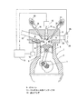
図1は本発明を採用した実施形態の火花点火式直噴エンジンの概略構成図である。
この図1に示すように、このエンジンEは、いわゆる4サイクルのレシプロエンジンであり、クランクシャフト1を回転自在に支持するシリンダブロック2と、シリンダブロック2の上部に配置されたシリンダヘッド3とで一体的に構成している。またこのシリンダブロック2とシリンダヘッド3には、複数の気筒4を設けている。
Hereinafter, embodiments of the present invention will be described in detail with reference to the drawings.
FIG. 1 is a schematic configuration diagram of a spark ignition direct injection engine according to an embodiment of the present invention.
As shown in FIG. 1, the engine E is a so-called four-cycle reciprocating engine, and includes a
各気筒4には、コンロッド5を介してクランクシャフト1に連結されたピストン6と、ピストン上方に形成される燃焼室7とを設けている。
Each cylinder 4 is provided with a
シリンダヘッド3の下面には、気筒4毎に燃焼室7の天井壁部8を形成している。この天井壁部8は、中央部分からシリンダヘッド3下端まで延びる2つの対向する傾斜面8a,8bを有する、いわゆるペントルーフ型となっている。
On the lower surface of the
前記燃焼室7の天井壁部8には、各々独立した2つの吸気ポート9と排気ポート10が設けられ、吸気2弁16、排気2弁17の4弁構成としている。
The
燃焼室7の側縁部には、燃料供給システムに接続されているマルチホール型インジェクタ11を斜め下方を向いて設置している。このマルチホール型インジェクタ11は、燃料供給システム12がコントロールユニット13からの燃料噴射パルスを受けることで、このパルス幅に対応する燃料を、燃焼室7に噴射するように構成している。
なお、このマルチホール型インジェクタ11の詳細構造については、後述する。
A
The detailed structure of the
また、各気筒4には、シリンダヘッド3に固定されて、燃焼室7内に電極を臨ませて配置される点火プラグ14を設けている。この点火プラグ14は、燃焼室7の略中央位置に配置している。点火プラグ14には、電子制御による点火タイミングのコントロール可能な点火回路15が接続されており、この点火回路15によって制御されるように構成している。
Further, each cylinder 4 is provided with a
各気筒4の吸気弁16及び排気弁17には、それぞれタペットユニット18,19が設けられている。このタペットユニット18,19は、シリンダヘッド3に設けられた動弁機構のカム軸のカム20,21によって、周期的に駆動されるように構成している。
エンジンEの吸気ポート9には、インテークマニホールドの分岐吸気管22が接続されている。分岐吸気管22は気筒毎に設けられており、それぞれがインテークマニホールドに等長の吸気経路を形成した状態で接続されている。
A
次に、排気ポート10には、各気筒に2つ一組で形成された二股状の分岐排気管23が接続されている。各分岐排気管23の下流側には、排気ガスの浄化を行なう触媒コンバータ24を設置している。この触媒コンバータ24には、触媒温度を検出する触媒温度センサ25を設けており、活性化温度まで触媒が昇温したか否かを検出するようにしている。
Next, the
コントロールユニット13は、CPU等で構成しており、図示しない入力センサ(クランク角センサ等)や前述の触媒温度センサ25等の入力要素と、前述した燃料供給システム12や点火回路15等の出力要素4を、接続することにより、エンジンの運転状態を制御するように構成している。
The
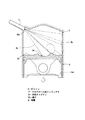
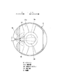
図2はマルチホール型インジェクタとピストンと点火プラグの詳細構造を示した斜視図であり、図3は(a)ピストン冠面の平面図と(b)ピストン冠面のA−A線矢視断面図である。
図2に示すように、マルチホール型インジェクタ11は、先端の噴射面11aが斜め下方に向くように設置しており、ピストン6の冠面30側に向けて複数の噴霧Gを噴射するように構成している。
2 is a perspective view showing a detailed structure of a multi-hole type injector, a piston, and a spark plug. FIG. 3 is (a) a plan view of a piston crown surface and (b) a cross section taken along line AA of the piston crown surface. FIG.
As shown in FIG. 2, the
このマルチホール型インジェクタ11の噴射面11aには、5つの噴口40…を設けている。具体的には、噴射面詳細図に示すように、上段中央に第一噴口40aを、二段目中央に第二噴口40bを、三段目左右両側に第三噴口40cと第四噴口40dを、下段中央に第五噴口40eを、それぞれ並ぶように設けている。
On the
このように、各噴口40…を設けることで、各噴口40から噴射される噴霧Gを、斜め下方に向かって筒内に満遍なく均等に噴射することができる。よって、通常運転時の均質燃焼時には、全筒内全てに燃料が行き渡り、効率的燃焼させることができる。
Thus, by providing each
また、後述するように、エンジン冷間時に、噴射タイミングを適切に制御することで、弱成層状態を筒内(4)に生成することもできる。
ここで、弱成層状態とは、点火プラグ周りの混合気の濃度を濃くして、その周囲の混合気を薄くなるように、筒内(4)の混合気比率を調整する状態をいう。
In addition, as will be described later, a weak stratification state can be generated in the cylinder (4) by appropriately controlling the injection timing when the engine is cold.
Here, the weakly stratified state refers to a state in which the mixture ratio in the cylinder (4) is adjusted so that the concentration of the air-fuel mixture around the spark plug is increased and the air-fuel mixture around the spark plug is reduced.
また、各噴口40…は、極小の径(例えば、0.1mm程度)で形成されており、この径や向き等によって、各噴口40…からの噴射量や指向方向が決定される。 Each of the nozzle holes 40 is formed with a very small diameter (for example, about 0.1 mm), and the injection amount and the directing direction from each of the nozzle holes 40 are determined by the diameter, the direction, and the like.
各噴霧G…の指向方向は、各噴口40…の位置に対応して設定されており、第一噴口40aからの第一噴霧Gaが最も上方を指向して、第二噴口40bからの第二噴霧Gbがその下方で中央を指向して、第三噴口40cからの第三噴霧Gcと、第四噴口40dからの第四噴霧Gdが、さらにその下方で左右外方側を指向して、第五噴口40eからの第五噴霧Geが最も下方で中央を指向するように設定されている。なお、第一噴霧Gaは、図2にも示すように、点火プラグ14の電極14aに燃料が付着しないように、電極14aよりも下方位置を指向するように設定されている。
The directing direction of each spray G ... is set corresponding to the position of each
この実施形態のピストン6は、ピストン冠面30にクランク軸方向に沿って対向する一対の傾斜面31a,31bを有する隆起部31を形成している。この隆起部31の傾斜面31a,31bは、前述した燃焼室7のペントルーフ型の天井壁部8に沿うように、ペントルーフ形状で傾斜するように形成している。
The
また、隆起部31のインジェクタ側、反インジェクタ側には、ピストン冠面30の基準面となる水平面部32,33をそれぞれ設けている。そして、この水平面部32,33には、吸気弁16と排気弁17にそれぞれ対応するように、吸気弁リセス32aと排気弁リセス33aを形成している。
Further, on the injector side and the non-injector side of the raised
この隆起部31の中央には、平面視略円形の凹状キャビティ34を形成している。この凹状キャビティ34は、略半球面状に形成された内周面35と、略水平面状に形成された平底面36と、を備えており、ピストン6が上死点に位置した際には、点火プラグ14の電極14aを中心とした略球状の燃焼空間を構成するようにしている。
A
このように、凹状キャビティ34を形成して、略球面状の燃焼空間を構成することで、圧縮比が極めて高いエンジンにすることができ、エンジン効率を高めることができる。
In this way, by forming the
図3(a)に示すように、吸気側の傾斜面31には、噴霧を受ける受け面37を形成している。この受け面37は、一段凹んだ平面視略U字形状の凹部で形成している。このU字形状は、キャビティ側(反インジェクタ側)が徐々に広くなるように形成しており、後述するように、噴霧Gを受けた際に噴霧Gを凹状キャビティ34内に案内するようにしている。
As shown in FIG. 3A, a receiving
この受け面37の上部の一部を、凹状キャビティ34にかかるように形成することで、図3(b)に示すように、凹状キャビティ34のインジェクタ側上縁端34aが、反インジェクタ側上縁端34bよりも下方側に位置するように設定している。
このため、後述するように、マルチホール型インジェクタ11から噴射された噴霧(Ga、Gb…)が、凹状キャビティ34内に、入り易く、且つ、出にくくなる。
By forming a part of the upper portion of the receiving
For this reason, as will be described later, the spray (Ga, Gb...) Sprayed from the
なお、図3(a)に示すように、隆起部31の凹状キャビティ34の両側の頂部分には上面部38,38を形成している。この上面部38,38は、外側端をやや下げた傾斜面で構成している。こうすることで、ピストン6が上死点にある場合であっても、筒内(4)上部で吸気側と排気側を連通する連通空間を形成することができる。
In addition, as shown to Fig.3 (a), the
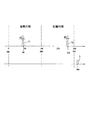
次に、図4、図5、図6により、エンジン冷間時におけるエンジン運転状態(燃料噴射状態)を説明する。図4はエンジン冷間時の燃料噴射タイミングと点火タイミングのタイムチャートであり、図5は吸気行程での燃料噴射状態を示す側面図であり、図6は圧縮行程での燃料噴射状態を示す側面図である。 Next, the engine operating state (fuel injection state) when the engine is cold will be described with reference to FIGS. 4 is a time chart of fuel injection timing and ignition timing when the engine is cold, FIG. 5 is a side view showing the fuel injection state in the intake stroke, and FIG. 6 is a side view showing the fuel injection state in the compression stroke. FIG.
コントロールユニット13で制御されるマルチホール型インジェクタ11と点火プラグ14は、エンジン冷間時には、図4のタイムチャートに示すように制御される。
The
すなわち、触媒温度センサ25等でエンジン冷間状態を検出した際には、燃料噴射タイミングが吸気行程で1回、圧縮行程で1回の合計2回に設定され、1サイクル当りの燃料噴射が2分割で行われる。
That is, when the engine cold state is detected by the
具体的には、例えば、クランク角度80度(以下、「°CA」とする)に一回目の燃料噴射F1が終了して、325°CAに二回目の燃料噴射F2が終了するように設定している。なお、各噴射パルスの幅w1,w2は、各噴射タイミングにおける燃料噴射量に比例するように設定しており、この二回の燃料噴射量の合計が、ほぼ理論空燃比となるような燃料噴射量に設定している。 Specifically, for example, the first fuel injection F1 is finished at a crank angle of 80 degrees (hereinafter referred to as “° CA”), and the second fuel injection F2 is finished at 325 ° CA. ing. The widths w1 and w2 of each injection pulse are set to be proportional to the fuel injection amount at each injection timing, and the fuel injection is such that the sum of the two fuel injection amounts is substantially the stoichiometric air-fuel ratio. The amount is set.
このように、2分割で燃料を噴射することにより、まず、1回目の燃料噴射F1によって、燃料を早期に筒内で気化霧化でき、その後、2回目の燃料噴射F2で、点火プラグ14周りに、混合気の濃いリッチな層を形成できる。すなわち、このような2分割の噴射タイミングによって、筒内をいわゆる弱成層化することができるのである。
In this way, by injecting the fuel in two parts, the fuel can be vaporized and atomized in the cylinder at an early stage by the first fuel injection F1, and then around the
そして、その後、上死点(TDC)を経過した後、380°CA(=排気行程の20°CA)で点火プラグ14を点火している。すなわち、排気行程に入る時期まで点火タイミングSを遅角しているのである。
Then, after the top dead center (TDC) has elapsed, the
このように、点火タイミングSを遅角することで、エンジンの燃焼エネルギーが熱エネルギーに多く使われることになり、排気温度が高いまま、排気ガスが排気側に排出されることになる。 As described above, by retarding the ignition timing S, the combustion energy of the engine is largely used for heat energy, and the exhaust gas is discharged to the exhaust side while the exhaust temperature is high.
このため、触媒コンデンサ24には、温度の高い排気ガスが供給されて、早期に触媒コンデンサ24の温度を上昇させることができ、触媒を活性化することができる。
よって、エンジン始動時などにおいて、早期に排気ガスを浄化することができる。
For this reason, exhaust gas having a high temperature is supplied to the
Therefore, exhaust gas can be purified at an early stage when the engine is started.
なお、点火プラグ14の点火タイミングSを遅角すると、燃焼状態が不安定になり、燃焼が確実に生じないおそれがある。しかし、本実施形態では、筒内を確実に弱成層化しているため、点火タイミングSが大幅に遅角したとしても、安定した燃焼状態を得ることができる。
Note that if the ignition timing S of the
図5に示すように、吸気行程での燃料噴射(1回目の燃料噴射F1)では、最下部の第五噴口40eから噴射された第五噴霧Geが、ピストン冠面30の凹状キャビティ34に入るように設定されている。すなわち、最も下方に指向する第五噴霧Geが、筒内4の側壁面4a(ライナー)に到達(付着)することなく、ピストン冠面30に指向するように、噴射されるのである。
As shown in FIG. 5, in the fuel injection in the intake stroke (first fuel injection F <b> 1), the fifth spray Ge injected from the lowermost
このように、第五噴霧Geがピストン冠面30を指向するように、燃料が噴射されることで、筒内4で最も温度が低い側壁面4a(ライナー)の下部4a1に、燃料が付着することがなく、吸気行程での燃料の気化霧化を促進することができる。このため、排気ガスに未燃ガスであるHCが含有されることを防ぐことができる。
In this way, the fuel is injected so that the fifth spray Ge is directed to the
また、90°CA近傍で燃料を噴射することで、ピストンスピードが最も速く、筒内流動が最も大きい時期に、燃料を噴射することになるため、気化霧化をより促進することができる。 Further, by injecting fuel in the vicinity of 90 ° CA, the fuel is injected at the time when the piston speed is the fastest and the in-cylinder flow is the largest, so vaporization atomization can be further promoted.
図6に示すように、圧縮行程での燃料噴射(2回目の燃料噴射F2)では、最上部の第一噴口40aから噴射された第一噴霧Gaがピストン冠面30の凹状キャビティ34を指向するように設定されている。すなわち、最も上方に指向する第一噴霧Gaが、凹状キャビティ34の内周面35に指向するように設定されているのである。
As shown in FIG. 6, in the fuel injection in the compression stroke (second fuel injection F <b> 2), the first spray Ga injected from the uppermost
一方、第二噴霧Gbは、凹状キャビティ34手前の受け面37に指向するように設定されている。もっとも、このように、第二噴霧Gbが受け面37に指向しても、第二噴霧Gbは凹状キャビティ34内に入ることになる。すなわち、受け面37に衝突して勢いが弱まった第二噴霧Gbは、第一噴霧Gaが通過した後に発生する負圧によって、凹状キャビティ34内に引き込まれるのである。
On the other hand, the second spray Gb is set so as to be directed to the receiving
また、第二噴霧Gbの下方に位置する第五噴霧Geも、受け面37及びその手前の水平面部32に指向するように設定されている。もっとも、この第五噴霧Geも第二噴霧Gb同様に、第一噴霧Gaが発生した負圧によって凹状キャビティ34内に引き込まれる。
The fifth spray Ge located below the second spray Gb is also set so as to be directed to the receiving
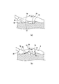
これらの引き込み挙動について、図7の模式図を利用して説明する。図7の(a)は噴射直後の側面模試図、(b)はその後の側面模式図である。 These pull-in behaviors will be described using the schematic diagram of FIG. FIG. 7A is a schematic side view immediately after injection, and FIG. 7B is a schematic side view thereafter.
(a)に示すように、第一噴霧Gaは、凹状キャビティ34の略半球面状の内周面35に、指向するように噴射される。
このため、第一噴霧Gaは、(b)に示すように、内周面35の円弧状傾斜面35aに案内されて、上方にスムーズに反転して、点火プラグ14側(天井壁部8側)に向かうことになる。
As shown to (a), the 1st spray Ga is injected so that it may direct to the substantially hemispherical inner
For this reason, as shown in (b), the first spray Ga is guided by the arc-shaped
一方、(a)に示すように、第二噴霧Gbは、受け面37に指向するように噴射される。
このため、第二噴霧Gbは、受け面37に衝突して勢いが弱まり、受け面37の上方を漂うことになる。しかし、(b)に示すように、第一噴霧Gaが通過した後には、凹状キャビティ34内に引き込む負圧が発生しているため、第二噴霧Gbは、この負圧によって、凹状キャビティ34内に引き込まれる。
このように、第二噴霧Gbが凹状キャビティ34に引き込まれることで、点火プラグ14周りに、濃い混合気を多く位置させることができる。
On the other hand, as shown in (a), the second spray Gb is injected so as to be directed toward the receiving
For this reason, the second spray Gb collides with the receiving
As described above, since the second spray Gb is drawn into the
そして、第二噴霧Gbだけでなく、その後方の第五噴霧Geも、受け面37と水平面部32に衝突して勢いが弱まった状態で、負圧によって凹状キャビティ34内に引き込まれる。
このため、第五噴霧Geも、凹状キャビティ34内に引き込まれることになり、点火プラグ14周りに、より濃い混合気が多く位置することになる。
また、図8の噴射状態を示した平面図に示すように、第一噴霧と重なるように噴射される第二噴霧Gbは、傾斜面31aから一段凹んだ受け面37に噴射されるため、側方側(ライナー側)に漏れることがなく、確実に凹状キャビティ34内に案内されることになる。
Then, not only the second spray Gb but also the fifth spray Ge behind the second spray Gb is drawn into the
For this reason, the fifth spray Ge is also drawn into the
Further, as shown in the plan view showing the injection state in FIG. 8, the second spray Gb that is injected so as to overlap the first spray is injected from the
特に、受け面37は、キャビティ側(反インジェクタ側)に向かって、徐々に広くなる略U字形状で形成しているため、第二噴霧Gbの流れが阻害されることなく、確実に凹状キャビティ34内に案内することができる。
In particular, the receiving
また、第五噴霧Geも、第一噴霧Gaと第二噴霧Gb同様に、中央に位置して、平面視で重なるように噴射されるため、この受け面37による案内機能を受けることができ、キャビティ内に確実に案内されることになる。
Moreover, since the fifth spray Ge is also sprayed so as to be overlapped in a plan view like the first spray Ga and the second spray Gb, it can receive a guide function by the receiving
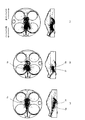
図9〜図12は、この実施形態の噴射状態のシミュレーション図である。図9は325°CAのシミュレーション図、図10は340°CAのシミュレーション図、図11は350°CAのシミュレーション図、図12は360°CAのシミュレーション図である。また、各図において、(a)が第一噴霧の噴射状態、(b)が第二噴霧の噴射状態、(c)が第一噴霧の噴霧状態と第二噴霧の噴霧状態を組み合わせたものである。そして、上段が平面図、下端が側面図である。また、各ドッドが噴霧の液滴である。 9 to 12 are simulation diagrams of the injection state of this embodiment. 9 is a simulation diagram of 325 ° CA, FIG. 10 is a simulation diagram of 340 ° CA, FIG. 11 is a simulation diagram of 350 ° CA, and FIG. 12 is a simulation diagram of 360 ° CA. Moreover, in each figure, (a) is the injection state of the first spray, (b) is the injection state of the second spray, (c) is a combination of the spray state of the first spray and the spray state of the second spray. is there. And the upper stage is a plan view and the lower end is a side view. Each dod is a spray droplet.
図9に示すように、噴射完了直後の325°CAでは、(a)のように、第一噴霧Gaは、凹状キャビティ34内に噴射される。また、第二噴霧Gbは、(b)のように受け面37に衝突して上方に漂うようになっている。このため、(c)のように、インジェクタ側には、多くの液滴が位置することになる。
As shown in FIG. 9, at 325 ° CA immediately after the completion of injection, the first spray Ga is injected into the
図10に示すように、その後の340°CAでは、(a)のように、第一噴霧Gaは、凹状キャビティ34内の内周面35に当接して上方に案内される。また、第二噴霧Gbは、(b)のように、第一噴霧Gaが通過した際に生じる負圧によって、凹状キャビティ34内(図面では上方)に引き込まれる。このため、(c)のように、点火プラグ14の周りには、多くの液滴が位置することになる。
As shown in FIG. 10, at the subsequent 340 ° CA, the first spray Ga is in contact with the inner
図11に示すように、その後の350°CAでは、(a)のように、第一噴霧Gaは、凹状キャビティ34の一方側に偏る。また、第二噴霧Gbは、(b)のように、凹状キャビティ34を中心に広がる。このため、(c)のように、点火プラグ14の周りには、液滴が位置することになる。なお、図10よりも、液滴が減少しているのは、液滴が順調に蒸発(気化)しているからである。
As shown in FIG. 11, in the subsequent 350 ° CA, the first spray Ga is biased to one side of the
図12に示すように、上死点の位置である360°CAでは、(a)に示すように、第一噴霧Gaは、凹状キャビティ34の一方側に偏った状態で気化している。また、第二噴霧Gbは、(b)のように、全体に広がって気化する。このため、(c)のように、液滴は、一部凹状キャビティ34の一方側に偏った状態で位置するものの、ほとんど気化することになる。
As shown in FIG. 12, at 360 ° CA, which is the position of the top dead center, as shown in (a), the first spray Ga is vaporized in a state of being biased to one side of the
以上のように、燃料を気化霧化して着火性能を高めているため、点火タイミングSを遅らせたとしても、確実に混合気を燃焼させることができ、排気ガスの温度を高めることができる。 As described above, since the fuel is vaporized and atomized to improve the ignition performance, even if the ignition timing S is delayed, the air-fuel mixture can be reliably burned and the temperature of the exhaust gas can be increased.
次に、このように構成した本実施形態の作用効果について説明する。
この実施形態では、隆起部31の傾斜面31aに凹状キャビティ34に繋がるように一段凹んだ受け面37を形成して、凹状キャビティ34のインジェクタ側上縁端34aを、反インジェクタ側上縁端34bより低く設定して、エンジン冷間時の運転領域において、圧縮行程後半に燃料を噴射することで、第一噴霧Gaが凹状キャビティ34に入るように噴射し、第二噴霧Gbが受け面37に衝突するように噴射するように設定している。
Next, the effect of this embodiment comprised in this way is demonstrated.
In this embodiment, a receiving
これにより、ピストン冠面30にペントルーフ状の隆起部31を形成することで、エンジンの圧縮比を高めることができつつも、第二噴霧Gbが第一噴霧Gaの通過によって発生した負圧によって凹状キャビティ34内に引き込まれる。そして、受け面37が隆起部31の傾斜面31aよりも一段低いため、第二噴霧Gbが受け面37で案内されて凹状キャビティ34内に導かれる。さらに、凹状キャビティ34のインジェクタ側上縁端34aが反インジェクタ側上縁端34bより低いため、第一噴霧Gaと第二噴霧Gbは、凹状キャビティ34に入り易くなり、且つ、出にくくなる。
As a result, the pent roof-shaped raised
このため、エンジンの圧縮比を高めつつも、第二噴霧Gbを負圧を利用して凹状キャビティ34内に引き込むにあたり、負圧の状態にさほど影響を受けずに、第二噴霧Gbを確実に凹状キャビティ34内に入れることができる。また、第二噴霧Gbを凹状キャビティ34内に入れても、第一噴霧Gaや第二噴霧Gbが凹状キャビティ34から出にくいため、多くの噴霧Gを凹状キャビティ34内に留めることができる。
For this reason, when the second spray Gb is drawn into the
よって、エンジン冷間時における触媒活性化促進を図る火花点火式直噴エンジンにおいて、エンジンEの圧縮比を高い状態で維持しつつ、凹状キャビティ34内に多くの噴霧Gを確実に入れて滞留させるようにして、エンジン冷間時の燃焼状態を安定させることができる。
Therefore, in a spark ignition direct injection engine that promotes catalyst activation when the engine is cold, a large amount of spray G is reliably put and retained in the
また、この実施形態では、受け面37を、平面視で凹状キャビティ34側に徐々に広がるように形成された略U字形状としている。
これにより、第二噴霧Gbが受け面37に衝突した後に、円滑に凹状キャビティ34側に案内されることになる。
よって、第二噴霧Gbをより確実に凹状キャビティ34に入れることが可能になり、濃い混合気を、確実に点火プラグ14周りに位置させることができる。
In this embodiment, the receiving
Thus, after the second spray Gb collides with the receiving
Therefore, it becomes possible to put the second spray Gb into the
また、この実施形態では、平面視で第二噴霧Gbと重なり、正面視で第二噴霧Gbの下側に位置する、第五噴霧Geを噴射する第五噴口40eを設けている。
これにより、燃料噴射時に、第二噴霧Gbの下側に第五噴霧Geが位置するため、第二噴霧Gbに加えて第五噴霧Geも受け面37等に衝突することになる。
このため、受け面37と水平面部32を利用して、上下に並ぶ第二噴霧Gbと第五噴霧Geを、凹状キャビティ34側に案内することができ、より多くの噴霧Gを凹状キャビティ34内に入れることができる。
よって、さらに多くの濃い混合気(噴霧G)を点火プラグ14周りに滞留させることができる。
Moreover, in this embodiment, the
Accordingly, since the fifth spray Ge is positioned below the second spray Gb during fuel injection, the fifth spray Ge collides with the receiving
Therefore, the second spray Gb and the fifth spray Ge arranged in the vertical direction can be guided to the
Therefore, a much richer air-fuel mixture (spray G) can be retained around the
また、この実施形態では、燃料噴射終了時期(F2)を、噴射終了時点が345°CAとなるように設定すると共に、点火プラグ14の点火時期(S)を、上死点後に設定している。
これにより、ピストン6が上死点近傍に位置するときに、燃料を噴射することで、ピストン冠面30に正確に噴霧を衝突させることができ、第一噴霧Gaと第二噴霧Gb等を、より正確に凹状キャビティ34内に入れることができる。そして、点火プラグ14の点火時期(S)を、上死点後に設定して、点火タイミングを遅らせたとしても、点火プラグ14周りに濃い混合気を滞留させているため、エンジンの燃焼性を確保することができる。
よって、点火タイミングを遅角して燃焼することが可能となり、排気ガス温度を昇温することができる。
In this embodiment, the fuel injection end timing (F2) is set so that the injection end time is 345 ° CA, and the ignition timing (S) of the
Thereby, when the
Therefore, combustion can be performed with retarded ignition timing, and the exhaust gas temperature can be raised.
また、この実施形態では、圧縮行程の燃料噴射(F2)に加えて、吸気行程でも燃料噴射(F1)を行なうものである。
上記構成によれば、燃料噴射を、吸気行程と圧縮行程で行なう二分割噴射(F1,F2)とすることにより、筒内をいわゆる弱成層化することができる。
よって、点火タイミングを遅角して燃焼させる場合の燃焼安定性を高めることができ、より確実に排気ガス温度を昇温することができる。
したがって、より安定的な燃焼を得つつ、排気系の昇温を図ることができ、触媒の活性化を図ることができる。
In this embodiment, in addition to the fuel injection (F2) in the compression stroke, the fuel injection (F1) is also performed in the intake stroke.
According to the above configuration, the cylinder interior can be so-called weakly stratified by performing the fuel injection in the two-split injection (F1, F2) performed in the intake stroke and the compression stroke.
Therefore, it is possible to improve the combustion stability when the ignition timing is retarded for combustion, and it is possible to raise the exhaust gas temperature more reliably.
Therefore, the temperature of the exhaust system can be raised while obtaining more stable combustion, and the catalyst can be activated.
以上、この発明の構成と前述の実施形態との対応において、
この発明のインジェクタは、実施形態のマルチホール型インジェクタ11に対応して、
以下、同様に、
キャビティは、凹状キャビティ34に対応し、
ペントルーフ状の斜面は、傾斜面31aに対応し、
第2の斜面は、受け面37に対応し、
第1噴口は、第一噴口40aに対応し、
第2噴口は、第二噴口40bに対応し、
第3噴口は、第五噴口40eに対応するも、
この発明は、前述の実施形態に限定されるものではなく、あらゆる火花点火式直噴エンジンに適用する実施形態を含むものである。
As described above, in the correspondence between the configuration of the present invention and the above-described embodiment,
The injector of the present invention corresponds to the
Similarly,
The cavity corresponds to the
The pent roof-shaped slope corresponds to the
The second slope corresponds to the receiving
The first nozzle hole corresponds to the
The second nozzle hole corresponds to the
The third nozzle hole corresponds to the
The present invention is not limited to the above-described embodiment, but includes an embodiment applied to any spark ignition direct injection engine.
6…ピストン
11…マルチホール型インジェクタ
14…点火プラグ
31…隆起部
31a…傾斜面
34…凹状キャビティ
37…受け面
40…噴口
G…噴霧
6 ...
Claims (5)
ピストン冠面には前記点火プラグに対応する凹状のキャビティを形成し、
該キャビティのインジェクタ側にはペントルーフ状の斜面を形成すると共に、
前記インジェクタには、上側に位置する第1噴霧を平面視で前記キャビティを指向するように噴射する第1噴口と、
平面視で前記第1噴霧と重なり、正面視で第1噴霧の下側に位置する第2噴霧を噴射する第2噴口と、の少なくとも2つの噴口を設け、
前記ペントルーフ状の斜面には、前記第2噴霧が衝突する一段低い第2の斜面を設けており、
該第2の斜面を前記キャビティに繋がるように形成することで、キャビティの周縁部のインジェクタ側を、反インジェクタ側より低く設定して、
エンジン冷間の運転領域で、圧縮行程後半の所定時期に、燃料を噴射することで第1噴霧がキャビティに入るように、第2噴霧が第2の斜面に衝突するように設定した
火花点火式直噴エンジン。 A spark ignition type direct injection engine comprising an injector provided with a plurality of injection holes for injecting a plurality of sprays obliquely downward on a peripheral edge of the combustion chamber ceiling wall, and having an ignition plug at the center of the combustion chamber ceiling wall,
A concave cavity corresponding to the spark plug is formed on the crown surface of the piston,
A pent roof-like slope is formed on the injector side of the cavity,
The injector has a first injection hole for injecting a first spray located on the upper side so as to be directed to the cavity in plan view;
Provided with at least two injection holes that overlap the first spray in a plan view and a second injection hole for injecting a second spray located below the first spray in a front view;
The pent roof-like slope is provided with a second slope that is one step lower where the second spray collides,
By forming the second inclined surface so as to be connected to the cavity, the injector side of the peripheral edge of the cavity is set lower than the anti-injector side,
A spark ignition type in which the second spray collides with the second slope so that the first spray enters the cavity by injecting fuel at a predetermined time in the second half of the compression stroke in the engine cold operating region. Direct injection engine.
請求項1記載の火花点火式直噴エンジン。 The spark-ignition direct injection engine according to claim 1, wherein the second inclined surface has a substantially U shape formed so as to gradually spread toward the cavity in a plan view.
請求項1又は2いずれか記載の火花点火式直噴エンジン。 3. The spark ignition direct injection engine according to claim 1, further comprising a third injection hole that injects a third spray that overlaps the second spray in a plan view and is located below the second spray in a front view.
前記点火プラグの点火時期を、上死点後に設定した
請求項1〜3いずれか記載の火花点火式直噴エンジン。 The fuel injection end timing of the predetermined timing is set to 3/4 or later of the compression stroke,
The spark ignition direct injection engine according to any one of claims 1 to 3, wherein an ignition timing of the spark plug is set after top dead center.
請求項4記載の火花点火式直噴エンジン。
The spark ignition type direct injection engine according to claim 4, wherein fuel injection is performed in an intake stroke in addition to fuel injection in the compression stroke.
Priority Applications (1)
| Application Number | Priority Date | Filing Date | Title |
|---|---|---|---|
| JP2008186155A JP5262386B2 (en) | 2008-07-17 | 2008-07-17 | Spark ignition direct injection engine |
Applications Claiming Priority (1)
| Application Number | Priority Date | Filing Date | Title |
|---|---|---|---|
| JP2008186155A JP5262386B2 (en) | 2008-07-17 | 2008-07-17 | Spark ignition direct injection engine |
Publications (2)
| Publication Number | Publication Date |
|---|---|
| JP2010024921A true JP2010024921A (en) | 2010-02-04 |
| JP5262386B2 JP5262386B2 (en) | 2013-08-14 |
Family
ID=41730991
Family Applications (1)
| Application Number | Title | Priority Date | Filing Date |
|---|---|---|---|
| JP2008186155A Expired - Fee Related JP5262386B2 (en) | 2008-07-17 | 2008-07-17 | Spark ignition direct injection engine |
Country Status (1)
| Country | Link |
|---|---|
| JP (1) | JP5262386B2 (en) |
Citations (3)
| Publication number | Priority date | Publication date | Assignee | Title |
|---|---|---|---|---|
| JPH11324679A (en) * | 1998-05-13 | 1999-11-26 | Nissan Motor Co Ltd | Cylinder injection type spark ignition engine |
| JP2005098117A (en) * | 2003-09-22 | 2005-04-14 | Mazda Motor Corp | Jupm spark ignition type direct-injection engine |
| JP2008057479A (en) * | 2006-09-01 | 2008-03-13 | Hitachi Ltd | Direct injection engine |
-
2008
- 2008-07-17 JP JP2008186155A patent/JP5262386B2/en not_active Expired - Fee Related
Patent Citations (3)
| Publication number | Priority date | Publication date | Assignee | Title |
|---|---|---|---|---|
| JPH11324679A (en) * | 1998-05-13 | 1999-11-26 | Nissan Motor Co Ltd | Cylinder injection type spark ignition engine |
| JP2005098117A (en) * | 2003-09-22 | 2005-04-14 | Mazda Motor Corp | Jupm spark ignition type direct-injection engine |
| JP2008057479A (en) * | 2006-09-01 | 2008-03-13 | Hitachi Ltd | Direct injection engine |
Also Published As
| Publication number | Publication date |
|---|---|
| JP5262386B2 (en) | 2013-08-14 |
Similar Documents
| Publication | Publication Date | Title |
|---|---|---|
| JP4582217B2 (en) | Spark ignition direct injection engine | |
| US10167797B2 (en) | Control system of engine | |
| US7104250B1 (en) | Injection spray pattern for direct injection spark ignition engines | |
| JP4501832B2 (en) | Spark ignition direct injection engine | |
| JP2006291839A (en) | Cylinder direct fuel injection type engine and its control method, and piston and fuel injection valve to be used for the same | |
| US20160356230A1 (en) | Control system of engine | |
| US7730871B2 (en) | Fuel injection control method for a direct injection spark ignition internal combustion engine | |
| JP4736518B2 (en) | In-cylinder direct injection internal combustion engine control device | |
| JP2008202483A (en) | Cylinder injection type internal combustion engine and injector used therefor | |
| JP4500790B2 (en) | Direct injection engine | |
| JP2007092633A (en) | Spark-ignition direct-ignition engine | |
| JP2010048212A (en) | Direct injection type gasoline engine | |
| WO2005121523A1 (en) | In-cylinder injection, spark ignited internal combustion engine | |
| JP2008157197A (en) | Cylinder injection type spark ignition internal combustion engine | |
| JP2009185687A (en) | Direct-injection spark-ignition internal combustion engine | |
| JP5136255B2 (en) | Spark ignition direct injection engine | |
| JP5071284B2 (en) | Spark ignition direct injection engine | |
| JP4803050B2 (en) | Fuel injection device for in-cylinder injection engine | |
| JP5262386B2 (en) | Spark ignition direct injection engine | |
| JP2006336502A (en) | Cylinder injection internal combustion engine | |
| JP4046055B2 (en) | In-cylinder internal combustion engine | |
| JP2010150970A (en) | Spark ignition direct injection engine | |
| JP5146248B2 (en) | In-cylinder direct injection internal combustion engine | |
| JP2007321619A (en) | Cylinder injection type spark ignition internal combustion engine | |
| JP2007321585A (en) | Cylinder injection type spark ignition internal combustion engine |
Legal Events
| Date | Code | Title | Description |
|---|---|---|---|
| A621 | Written request for application examination |
Free format text: JAPANESE INTERMEDIATE CODE: A621 Effective date: 20110523 |
|
| A521 | Written amendment |
Free format text: JAPANESE INTERMEDIATE CODE: A523 Effective date: 20120329 |
|
| A977 | Report on retrieval |
Free format text: JAPANESE INTERMEDIATE CODE: A971007 Effective date: 20120719 |
|
| A131 | Notification of reasons for refusal |
Free format text: JAPANESE INTERMEDIATE CODE: A131 Effective date: 20120724 |
|
| A521 | Written amendment |
Free format text: JAPANESE INTERMEDIATE CODE: A523 Effective date: 20120914 |
|
| TRDD | Decision of grant or rejection written | ||
| A01 | Written decision to grant a patent or to grant a registration (utility model) |
Free format text: JAPANESE INTERMEDIATE CODE: A01 Effective date: 20130402 |
|
| A61 | First payment of annual fees (during grant procedure) |
Free format text: JAPANESE INTERMEDIATE CODE: A61 Effective date: 20130415 |
|
| R150 | Certificate of patent or registration of utility model |
Free format text: JAPANESE INTERMEDIATE CODE: R150 Ref document number: 5262386 Country of ref document: JP Free format text: JAPANESE INTERMEDIATE CODE: R150 |
|
| LAPS | Cancellation because of no payment of annual fees |