JP2010023938A - Sheet transport apparatus - Google Patents
Sheet transport apparatus Download PDFInfo
- Publication number
- JP2010023938A JP2010023938A JP2008183939A JP2008183939A JP2010023938A JP 2010023938 A JP2010023938 A JP 2010023938A JP 2008183939 A JP2008183939 A JP 2008183939A JP 2008183939 A JP2008183939 A JP 2008183939A JP 2010023938 A JP2010023938 A JP 2010023938A
- Authority
- JP
- Japan
- Prior art keywords
- sheet
- inner guide
- spring
- guide
- guide member
- Prior art date
- Legal status (The legal status is an assumption and is not a legal conclusion. Google has not performed a legal analysis and makes no representation as to the accuracy of the status listed.)
- Granted
Links
Images


Classifications
-
- B—PERFORMING OPERATIONS; TRANSPORTING
- B65—CONVEYING; PACKING; STORING; HANDLING THIN OR FILAMENTARY MATERIAL
- B65H—HANDLING THIN OR FILAMENTARY MATERIAL, e.g. SHEETS, WEBS, CABLES
- B65H5/00—Feeding articles separated from piles; Feeding articles to machines
- B65H5/36—Article guides or smoothers, e.g. movable in operation
- B65H5/38—Article guides or smoothers, e.g. movable in operation immovable in operation
-
- B—PERFORMING OPERATIONS; TRANSPORTING
- B65—CONVEYING; PACKING; STORING; HANDLING THIN OR FILAMENTARY MATERIAL
- B65H—HANDLING THIN OR FILAMENTARY MATERIAL, e.g. SHEETS, WEBS, CABLES
- B65H2402/00—Constructional details of the handling apparatus
- B65H2402/30—Supports; Subassemblies; Mountings thereof
- B65H2402/31—Pivoting support means
-
- B—PERFORMING OPERATIONS; TRANSPORTING
- B65—CONVEYING; PACKING; STORING; HANDLING THIN OR FILAMENTARY MATERIAL
- B65H—HANDLING THIN OR FILAMENTARY MATERIAL, e.g. SHEETS, WEBS, CABLES
- B65H2402/00—Constructional details of the handling apparatus
- B65H2402/50—Machine elements
- B65H2402/54—Springs, e.g. helical or leaf springs
-
- B—PERFORMING OPERATIONS; TRANSPORTING
- B65—CONVEYING; PACKING; STORING; HANDLING THIN OR FILAMENTARY MATERIAL
- B65H—HANDLING THIN OR FILAMENTARY MATERIAL, e.g. SHEETS, WEBS, CABLES
- B65H2404/00—Parts for transporting or guiding the handled material
- B65H2404/60—Other elements in face contact with handled material
- B65H2404/61—Longitudinally-extending strips, tubes, plates, or wires
- B65H2404/611—Longitudinally-extending strips, tubes, plates, or wires arranged to form a channel
- B65H2404/6111—Longitudinally-extending strips, tubes, plates, or wires arranged to form a channel and shaped for curvilinear transport path
-
- B—PERFORMING OPERATIONS; TRANSPORTING
- B65—CONVEYING; PACKING; STORING; HANDLING THIN OR FILAMENTARY MATERIAL
- B65H—HANDLING THIN OR FILAMENTARY MATERIAL, e.g. SHEETS, WEBS, CABLES
- B65H2601/00—Problem to be solved or advantage achieved
- B65H2601/10—Ensuring correct operation
- B65H2601/11—Clearing faulty handling, e.g. jams
-
- B—PERFORMING OPERATIONS; TRANSPORTING
- B65—CONVEYING; PACKING; STORING; HANDLING THIN OR FILAMENTARY MATERIAL
- B65H—HANDLING THIN OR FILAMENTARY MATERIAL, e.g. SHEETS, WEBS, CABLES
- B65H2801/00—Application field
- B65H2801/03—Image reproduction devices
- B65H2801/06—Office-type machines, e.g. photocopiers
Landscapes
- Engineering & Computer Science (AREA)
- Mechanical Engineering (AREA)
- Feeding Of Articles By Means Other Than Belts Or Rollers (AREA)
- Delivering By Means Of Belts And Rollers (AREA)
Abstract
Description
本発明は、シートを搬送するシート搬送装置に関する。 The present invention relates to a sheet conveying apparatus that conveys a sheet.
例えば、電子写真方式の画像形成装置においては、静電潜像を感光体ドラム表面に形成し、現像剤により感光体ドラム表面の静電潜像を現像して、感光体ドラム表面にトナー像を形成し、感光体ドラムと転写部材間のニップ域にシートを挟み込んで搬送しつつ、トナー像を感光体ドラムからシートに転写し、シートを加熱及び加圧して、トナー像をシート上に定着させている。 For example, in an electrophotographic image forming apparatus, an electrostatic latent image is formed on the surface of a photosensitive drum, the electrostatic latent image on the surface of the photosensitive drum is developed with a developer, and a toner image is formed on the surface of the photosensitive drum. The toner image is transferred from the photosensitive drum to the sheet while the sheet is sandwiched and conveyed in the nip area between the photosensitive drum and the transfer member, and the sheet is heated and pressurized to fix the toner image on the sheet. ing.
このような画像形成装置にはシート搬送装置が組み込まれており、このシート搬送装置によりシートが給紙トレイから引き出されて搬送される。また、シート搬送装置の搬送経路においては、感光体ドラムと転写部材間のニップ域よりもシート搬送方向上流側にレジストローラ(PS(Paper Stop)ローラとも称する)を設けており、このレジストローラにシートの先端を付き当てて、シートを撓ませ、このシートの弾性力によりシートの先端をレジストローラと平行に揃えてから、レジストローラによりシートをニップ域へと搬送している。これにより、シートが斜めになってニップ域を通過することが防止され、トナー像がシートに斜めに転写されずに済む。 In such an image forming apparatus, a sheet conveying apparatus is incorporated, and the sheet is pulled out from the sheet feeding tray and conveyed by the sheet conveying apparatus. In addition, a registration roller (also referred to as a PS (Paper Stop) roller) is provided upstream of the nip area between the photosensitive drum and the transfer member in the sheet conveyance direction in the conveyance path of the sheet conveyance device. The front end of the sheet is applied to bend the sheet, and the front end of the sheet is aligned parallel to the registration roller by the elastic force of the sheet, and then the sheet is conveyed to the nip region by the registration roller. This prevents the sheet from being inclined and passing through the nip region, and the toner image is not transferred to the sheet at an angle.
また、特許文献1では、レジストローラよりもシート搬送方向上流側において、シートのガイド部材をバネにより付勢して、このガイド部材によりシート先端をレジストローラに効果的に押し付けて、レジストローラによりシート先端を確実に揃えるようにしている。
ところで、シート搬送装置においては、搬送途中のシート詰まり、所謂ジャムが発生することがある。このため、装置の複数箇所を開放可能にして、開放した箇所で詰まったシートを除去することができるようにしている。 By the way, in the sheet conveying apparatus, sheet jamming during the conveyance, that is, so-called jam may occur. For this reason, a plurality of locations of the apparatus can be opened, and sheets jammed at the opened locations can be removed.
しかしながら、特許文献1のようにシートのガイド部材を付勢するバネを設けている箇所が開放された場合は、ユーザがそのバネを触り得るので、不注意な作業等によりバネが取り外されたり、バネそのものが壊されたりすることがあり、これが装置の故障の原因となった。 However, when the location where the spring for biasing the guide member of the seat is opened as in Patent Document 1, the user can touch the spring, so the spring is removed by careless work or the like, The spring itself could be broken, which caused the device to malfunction.
そこで、本発明は、上記従来の問題点に鑑みなされたものであり、ガイド部材近傍を開放させた状態でも、ガイド部材を付勢するバネに対する接触が困難なシート搬送装置を提供することを目的とする。 Accordingly, the present invention has been made in view of the above-described conventional problems, and an object thereof is to provide a sheet conveying apparatus that is difficult to contact with a spring that biases the guide member even when the vicinity of the guide member is opened. And
上記課題を解決するために、本発明のシート搬送装置は、シート搬送経路の一部を形成するガイド部材がバネにより弾性的に位置決めされており、装置の保守のために該ガイド部材近傍を開放させることが可能なシート搬送装置において、前記バネの一端側を支持するための凹部を前記ガイド部材に形成すると共に、該バネの他端側を支持するための凹部を該ガイド部材の支持部材に形成し、該ガイド部材の凹部と前記支持部材の凹部の内側に該バネを配置して囲い、該ガイド部材と該支持部材の間に該バネを挟み込んでいる。 In order to solve the above problems, in the sheet conveying apparatus of the present invention, a guide member forming a part of the sheet conveying path is elastically positioned by a spring, and the vicinity of the guide member is opened for maintenance of the apparatus. In the sheet conveying apparatus that can be made, a recess for supporting one end of the spring is formed in the guide member, and a recess for supporting the other end of the spring is formed in the support member of the guide member. The spring is disposed and enclosed inside the concave portion of the guide member and the concave portion of the support member, and the spring is sandwiched between the guide member and the support member.
また、前記ガイド部材は、前記支持部材に対して回転移動可能に取り付けられており、前記バネの一端側又は他端側を該ガイド部材の凹部又は該支持部材の凹部に配置した後に、該ガイド部材を回転移動させて、該ガイド部材の凹部と該支持部材の凹部を対向させ、これらの凹部の内側に該バネを配置して囲っている。 The guide member is rotatably attached to the support member, and the guide member is disposed at one end or the other end of the spring in the recess of the guide member or the recess of the support member. The member is rotated and moved so that the concave portion of the guide member and the concave portion of the support member are opposed to each other, and the spring is disposed and enclosed inside these concave portions.
更に、前記ガイド部材は、前記支持部材に対して着脱自在に取り付けられており、該支持部材を装置本体側に取り付けた状態では、該支持部材に対する該ガイド部材の着脱方向の移動が禁止される。 Furthermore, the guide member is detachably attached to the support member. When the support member is attached to the apparatus main body, movement of the guide member in the attachment / detachment direction with respect to the support member is prohibited. .
本発明によれば、ガイド部材の凹部と支持部材の凹部の内側にバネを配置して囲んでいるので、バネを設けている箇所が開放されても、バネが露見せず、不注意な作業等によりバネが取り外されたり、バネそのものが壊されたりすることがない。 According to the present invention, since the spring is arranged and surrounded inside the concave portion of the guide member and the concave portion of the support member, even if the portion where the spring is provided is opened, the spring does not show up and careless work is performed. The spring is not removed or the spring itself is not broken.
また、バネの一端側又は他端側をガイド部材の凹部又は支持部材の凹部に配置した後に、ガイド部材を回転移動させて、ガイド部材の凹部と支持部材の凹部を対向させ、これらの凹部の内側にバネを配置して囲っているので、バネを組み込む作業が簡単かつ容易である。 Also, after one end or the other end of the spring is disposed in the recess of the guide member or the recess of the support member, the guide member is rotated and moved so that the recess of the guide member and the recess of the support member face each other. Since the spring is arranged on the inner side and surrounded, the work of incorporating the spring is simple and easy.
更に、支持部材を装置本体側に取り付けた状態では、該支持部材に対する該ガイド部材の着脱方向の移動が禁止される。この場合は、支持部材を取り外さなければ、ガイド部材を取り外すことができず、更にはバネを取り外すこともできない。このため、バネを取り外したり壊すことが困難になる。 Further, when the support member is attached to the apparatus main body, movement of the guide member in the attaching / detaching direction with respect to the support member is prohibited. In this case, unless the support member is removed, the guide member cannot be removed, and furthermore, the spring cannot be removed. This makes it difficult to remove or break the spring.
以下、本発明の実施形態を添付図面を参照して詳細に説明する。 Hereinafter, embodiments of the present invention will be described in detail with reference to the accompanying drawings.
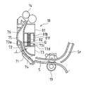
図1は、本発明のシート搬送装置の実施形態を適用した画像形成装置を示す側面図である。この画像形成装置は、原稿の画像を読取る原稿読取り装置Bと、原稿読取り装置Bにより読取られた原稿の画像又は外部から受信した画像をカラーもしくは単色で記録シートに記録形成する装置本体Aとを備えている。 FIG. 1 is a side view showing an image forming apparatus to which an embodiment of a sheet conveying apparatus of the present invention is applied. This image forming apparatus includes a document reading device B that reads an image of a document, and an apparatus main body A that records and forms an image of a document read by the document reading device B or an image received from outside on a recording sheet in color or single color. I have.
原稿読取り装置Bでは、原稿が原稿セットトレイ41にセットされると、ピックアップローラ44が原稿表面に押し付けられて回転され、原稿がトレイ41から引き出され、原稿がサバキローラ45と分離パッド46間を通過して1枚ずつに分離されてから搬送経路47へと搬送される。
In the document reading apparatus B, when the document is set on the document set
この搬送経路47では、原稿の先端がレジストローラ49に当接して、原稿の先端がレジストローラ49と平行に揃えられ、この後に原稿がレジストローラ49により搬送されて読取りガイド51と読取りガラス52間を通過する。このとき、第1走査部53の光源の光が読取りガラス52を介して原稿表面に照射され、その反射光が読取りガラス52を介して第1走査部53に入射し、この反射光が第1及び第2走査部53、54のミラーで反射されて結像レンズ55へと導かれ、結像レンズ55によって原稿表面の画像がCCD(Charge Coupled Device)56上に結像される。CCD56は、原稿表面の画像を読取り、原稿表面の画像を示す画像データを出力する。更に、原稿は、搬送ローラ57により搬送され、排紙ローラ58を介して排紙トレイ59に排出される。
In this
また、原稿台ガラス61上に載置された原稿を読取ることができる。レジストローラ49、読取りガイド51、排紙トレイ59等とそれらよりも上側の部材とは、一体化されて、原稿読取り装置Bの背面側で開閉可能に枢支されたカバー体となっており、この上側のカバー体を開くと、原稿台ガラス61が解放されて、原稿台ガラス61上に原稿を載置することができる。原稿が載置されて、カバー体が閉じられると、第1及び第2走査部53、54が副走査方向に移動されつつ、第1走査部53によって原稿台ガラス61上の原稿表面が露光され、第1及び第2走査部53、54によって原稿表面からの反射光が結像レンズ55へと導かれ、結像レンズ55によって原稿表面の画像がCCD56上に結像される。このとき、第1及び第2走査部53、54が相互に所定の速度関係を維持しつつ移動されて、原稿表面→第1及び第2走査部53、55→結像レンズ55→CCD56という反射光の光路の長さが変化しないように第1及び第2走査部53、54の位置関係が常に維持され、これによりCCD56上での原稿表面の画像のピントが常に正確に維持される。
In addition, it is possible to read a document placed on the
こうして読取られた原稿の画像全体は、画像データとして画像形成装置の装置本体Aへと送受され、装置本体Aにおいて画像が記録シートに記録される。 The entire image of the original read in this way is transmitted and received as image data to the apparatus main body A of the image forming apparatus, and the image is recorded on the recording sheet in the apparatus main body A.
一方、画像形成装置の装置本体Aは、レーザ露光装置1、現像装置2、感光体ドラム3、帯電器5、クリーナ装置4、中間転写ベルト装置8、定着装置12、シート搬送装置18、給紙トレイ10、及び排紙トレイ15等により構成されている。
On the other hand, the apparatus main body A of the image forming apparatus includes a laser exposure device 1, a developing device 2, a photosensitive drum 3, a charger 5, a cleaner device 4, an intermediate
画像形成装置の装置本体Aにおいて扱われる画像データは、ブラック(K)、シアン(C)、マゼンタ(M)、イエロー(Y)の各色を用いたカラー画像に応じたもの、又は単色(例えばブラック)を用いたモノクロ画像に応じたものである。従って、現像装置2(2a、2b、2c、2d)、感光体ドラム3(3a、3b、3c、3d)、帯電器5(5a、5b、5c、5d)、クリーナ装置4(4a、4b、4c、4d)は各色に応じた4種類の潜像を形成するようにそれぞれ4個ずつ設けられ、それぞれaがブラックに、bがシアンに、cがマゼンタに、dがイエローに対応付けられて、4つの画像ステーションが構成されている。 The image data handled in the apparatus main body A of the image forming apparatus is data corresponding to a color image using each color of black (K), cyan (C), magenta (M), yellow (Y), or a single color (for example, black ) In accordance with a monochrome image. Accordingly, the developing device 2 (2a, 2b, 2c, 2d), the photosensitive drum 3 (3a, 3b, 3c, 3d), the charger 5 (5a, 5b, 5c, 5d), the cleaner device 4 (4a, 4b, 4c and 4d) are provided in each of four types so as to form four types of latent images corresponding to the respective colors, a corresponding to black, b corresponding to cyan, c corresponding to magenta, and d corresponding to yellow. Four image stations are configured.
感光体ドラム3は、装置本体Aのほぼ中央に配置されている。 The photoconductor drum 3 is disposed in the approximate center of the apparatus main body A.
帯電器5は、感光体ドラム3の表面を所定の電位に均一に帯電させるための帯電手段であり、接触型であるローラ型やブラシ型の帯電器のほか、チャージャー型の帯電器が用いられる。 The charger 5 is a charging means for uniformly charging the surface of the photosensitive drum 3 to a predetermined potential. In addition to a contact type roller type or brush type charger, a charger type charger is used. .
レーザ露光装置1は、レーザダイオード及び反射ミラーを備えたレーザスキャニングユニット(LSU)であり、帯電された感光体ドラム3表面を画像データに応じて露光して、その表面に画像データに応じた静電潜像を形成する。 The laser exposure apparatus 1 is a laser scanning unit (LSU) provided with a laser diode and a reflection mirror, which exposes the surface of a charged photosensitive drum 3 according to image data and statically responds to the surface according to the image data. An electrostatic latent image is formed.
現像装置2は、感光体ドラム3上に形成された静電潜像を(K、C、M、Y)のトナーにより現像する。クリーナ装置4は、現像及び画像転写後に感光体ドラム3表面に残留したトナーを除去及び回収する。 The developing device 2 develops the electrostatic latent image formed on the photosensitive drum 3 with (K, C, M, Y) toner. The cleaner device 4 removes and collects toner remaining on the surface of the photosensitive drum 3 after development and image transfer.
感光体ドラム3の上方に配置されている中間転写ベルト装置8は、中間転写ベルト7、中間転写ベルト駆動ローラ21、従動ローラ22、中間転写ローラ6(6a、6b、6c、6d)、及び中間転写ベルトクリーニング装置9を備えている。
The intermediate
中間転写ベルト駆動ローラ21、中間転写ローラ6、従動ローラ22等は、中間転写ベルト7を張架して支持し、中間転写ベルト7を矢印C方向に周回移動させる。
The intermediate transfer
中間転写ローラ6は、中間転写ベルト7近傍に回転可能に支持され、中間転写ベルト7を介して感光体ドラム3に圧接され、感光体ドラム3のトナー像を中間転写ベルト7に転写するための転写バイアスを印加されている。
The intermediate transfer roller 6 is rotatably supported in the vicinity of the
中間転写ベルト7は、各感光体ドラム3a、3b、3c、3dに接触するように設けられており、各感光体ドラム3a、3b、3c、3d表面のトナー像を中間転写ベルト7に順次重ねて転写することによって、カラーのトナー像(各色のトナー像)を形成する。この転写ベルトは、厚さ100μm〜150μm程度のフィルムを用いて無端ベルト状に形成されている。
The
感光体ドラム3から中間転写ベルト7へのトナー像の転写は、中間転写ベルト7裏面に圧接されている中間転写ローラ6によって行われる。中間転写ローラ6には、トナー像を転写するために高電圧の転写バイアス(トナーの帯電極性(−)とは逆極性(+)の高電圧)が印加されている。中間転写ローラ6は、直径8〜10mmの金属(例えばステンレス)軸をベースとし、その表面は、導電性の弾性材(例えばEPDM、発泡ウレタン等)により覆われているローラである。この導電性の弾性材により、記録シートに対して均一に高電圧を印加することができる。
The transfer of the toner image from the photosensitive drum 3 to the
上述の様に各感光体ドラム3a、3b、3c、3d表面のトナー像は、中間転写ベルト7で積層され、画像データによって示されるカラーのトナー像となる。このように積層された各色のトナー像は、中間転写ベルト7と共に搬送され、中間転写ベルト7と接触する2次転写装置11によって記録シート上に転写される。
As described above, the toner images on the surfaces of the
中間転写ベルト7と2次転写装置11の転写ローラ11aとは、相互に圧接されてニップ域を形成する。また、2次転写装置11の転写ローラ11aには、中間転写ベルト7上の各色のトナー像を記録シートに転写させるための電圧(トナーの帯電極性(−)とは逆極性(+)の高電圧)が印加される。さらに、そのニップ域を定常的に得るために、2次転写装置11の転写ローラ11aもしくは中間転写ベルト駆動ローラ21の何れか一方を硬質材料(金属等)とし、他方を弾性ローラ等の軟質材料(弾性ゴムローラ、または発泡性樹脂ローラ等々)としている。
The
また、2次転写装置11によって中間転写ベルト7上のトナー像が記録シート上に完全に転写されず、中間転写ベルト7上にトナーが残留することがあり、この残留トナーが次工程でトナーの混色を発生させる原因となる。このため、中間転写ベルトクリーニング装置9によって残留トナーを除去及び回収する。中間転写ベルトクリーニング装置9には、例えばクリーニング部材として中間転写ベルト7に接触するクリーニングブレードが備えられており、クリーニングブレードが接触する部位で、従動ローラ22により中間転写ベルト7裏側が支持されている。
In addition, the toner image on the
給紙トレイ10は、記録シートを格納しておくためのトレイであり、装置本体Aの画像形成部の下側に設けられている。また、画像形成部の上側に設けられている排紙トレイ15は、印刷済みの記録シートをフェイスダウンで載置するためのトレイである。
The
また、装置本体Aには、給紙トレイ10の記録シートを2次転写装置11や定着装置12を経由させて排紙トレイ15に送るためのシート搬送装置18が設けられている。このシート搬送装置18は、Sの字形状のシート搬送経路Sを有し、シート搬送経路Sに沿って、ピックアップローラ16、レジスト前ローラ19、レジストローラ14、定着装置12、各搬送ローラ13、及び排紙ローラ17等を配置したものである。
Further, the apparatus main body A is provided with a
ピックアップローラ16は、給紙トレイ10の端部に設けられ、給紙トレイ10から記録シートを1枚ずつシート搬送経路Sに供給する呼び込みローラである。各搬送ローラ13及びレジスト前ローラ19は、記録シートの搬送を促進補助するための小型のローラであり、シート搬送経路Sに沿って複数箇所に設けられている。
The
レジストローラ14は、搬送されて来た記録シートを一旦停止させて、記録シートの先端を揃え、中間転写ベルト7と2次転写装置11間のニップ域で中間転写ベルト7上のカラーのトナー像が記録シートに転写されるように、感光体ドラム3及び中間転写ベルト7の回転にあわせて、記録シートをタイミングよく搬送する。
The
例えば、レジストローラ14は、中間転写ベルト7と2次転写装置11間のニップ域で中間転写ベルト7上のカラーのトナー像の先端が記録シートにおける画像形成範囲の先端に合うように、記録シートを搬送する。
For example, the
定着装置12は、トナー像が転写された記録シートを受け取り、この記録シートをヒートローラ31及び加圧ローラ32間に挟み込んで搬送する。
The fixing
ヒートローラ31は、所定の定着温度となるように制御されており、加圧ローラ32とともに記録シートを熱圧着することにより、記録シートに転写されたトナー像を溶融、混合、圧接し、記録シートに対して熱定着させる機能を有している。
The
各色のトナー像の定着後の記録シートは、排紙ローラ17によって排紙トレイ15上に排出される。
The recording sheet after fixing the toner images of the respective colors is discharged onto the
尚、画像形成ステーションPaだけを用いて、モノクロ画像を形成し、モノクロ画像を中間転写ベルト装置8の中間転写ベルト7に転写することも可能である。このモノクロ画像も、カラー画像と同様に、中間転写ベルト7から記録シートに転写され、記録シート上に定着される。
It is also possible to form a monochrome image using only the image forming station Pa and transfer the monochrome image to the
また、記録シートの表面だけではなく、両面の印字を行なう場合は、記録シートの表面の画像を定着装置12により定着した後に、記録シートをシート搬送経路Sの排紙ローラ17により搬送する途中で、排紙ローラ17を停止させてから逆回転させ、記録シートを反転経路Srに通して、記録シートの表裏を反転させてから、記録シートをレジストローラ14へと導き、記録シートの表面と同様に、記録シートの裏面に画像を記録して定着し、記録シートを排紙トレイ15に排出する。
When printing on both sides of the recording sheet as well as the recording sheet, after fixing the image on the surface of the recording sheet by the fixing
次に、シート搬送装置18の構成を詳しく説明する。シート搬送装置18において、レジストローラ14よりもシート搬送方向上流側には、シート搬送経路Sを大きな曲率で湾曲させた湾曲部71が形成されている。このような湾曲部71では、記録シートの腰が強くなる程、シートが詰まり易くなる傾向にある。
Next, the configuration of the
このため、シート搬送装置18では、湾曲部71を図2に示すように構成して、記録シートの腰が強くても、シート詰まりが生じ難いようにしている。
For this reason, in the
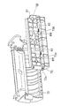
図2に示すようにシート搬送経路Sの湾曲部71は、外側ガイド72と内側ガイド73間に形成され、レジストローラ14よりもシート搬送方向上流側に、かつレジスト前ローラ19よりも下流側に位置する。
As shown in FIG. 2, the
外側ガイド72は、固定されている。また、内側ガイド73は、軸73aで揺動自在に軸支されている。シート搬送経路Sの支持フレーム81と内側ガイド73の上面73b間にコイルバネ82が挿入されており、コイルバネ82の弾性力により内側ガイド73が軸73a周りで時計回り方向に回転して、内側ガイド73の端部がストッパー74に当接し、内側ガイド73が位置決めされている。ストッパー74は、湾曲部71の奥の壁面に固定され、湾曲部71を通過する記録シートに接触したり干渉することはない。
The
また、レジストローラ14と湾曲部71間には、レジストローラ14に突き当たって撓んだ記録シートが収まるように、シート搬送経路Sの幅を広げてなる撓みスペース75を設けている。この撓みスペース75は、シート搬送経路Sのガイド76を湾曲させて窪ませることにより形成されている。
Further, a bending
尚、撓みスペース75を下方に拡大して湾曲部71につなげれば、湾曲部71の曲率を小さくすることができるが、撓みスペース75が拡大し過ぎると、記録シートの搬送精度が劣化するので、好ましくない。
If the bending
このようなシート搬送経路Sの湾曲部71において、内側ガイド73の端部がストッパー74に当接しているときには、外側ガイド72と内側ガイド73間の経路幅Jが一定となっている。この状態で、図3(a)に示すように64g/m2(坪量)程度の標準的な記録シートPがレジスト前ローラ19を介して湾曲部71に搬送されて来ると、この記録シートPに十分な柔軟性があるため、湾曲部71に沿って記録シートPが容易に湾曲し、記録シートPが湾曲部71を速やかに通過する。このとき、記録シートPが内側ガイド73に接しても、内側ガイド73が変位する程の力が該内側ガイド73に作用せず、外側ガイド72と内側ガイド73間の経路幅Jが一定に保たれたまま、記録シートPが搬送され、記録シートPの搬送精度が高く維持される。
In such a
また、図3(b)に示すように200g/m2(坪量)程度の厚紙の記録シートPが湾曲部71に搬送されて来ると、この記録シートPの腰が強いことから、湾曲部71に沿って記録シートPが湾曲し切れない。このため、記録シートPにより内側ガイド73が押圧されて、内側ガイド73がコイルバネ82の弾性力に抗して軸73a周りで反時計回り方向に回転して変位し、内側ガイド73が外側ガイド72から離間して、湾曲部71の経路幅が広くなる。この結果、記録シートPが十分に湾曲しなくても湾曲部71が速やかに通過して行く。また、外側ガイド72が固定されているので、記録シートが外側ガイド72の壁面に摺接しつつガイドされる。このため、記録シートPの搬送精度が損なわれることもない。
Further, as shown in FIG. 3B, when a thick recording sheet P having a thickness of about 200 g / m 2 (basis weight) is conveyed to the bending
こうして記録シートPが湾曲部71を通過すると、引き続いて記録シートPが撓みスペース75を通過し、記録シートPの先端がレジストローラ14に当接する。このとき、レジストローラ14の回転が一時的に停止されており、記録シートPの先端がレジストローラ14に当接したまま、レジスト前ローラ19による記録シートPの搬送が継続され、記録シートPが撓みスペース75内で撓み、この撓んだ記録シートPの弾性力により該記録シートPの先端がレジストローラ14と平行に揃えられる。この後、レジストローラ14が回転駆動されて、レジストローラ14により記録シートPが搬送される。これにより、記録シートPが斜めになって中間転写ベルト7と2次転写装置11間のニップ域を通過することが防止される。
When the recording sheet P passes through the
このようにシート搬送経路Sの湾曲部71を外側ガイド72と内側ガイド73間に形成し、内側ガイド73を軸73aで揺動自在に軸支し、腰の強い記録シートPが湾曲部71を通過するときには、記録シートPにより内側ガイド73が押圧されて変位し、湾曲部71の経路幅が広くなるようにしているので、腰の強い記録シートPであっても湾曲部71を速やかに通過することができ、シート詰まりが生じ難くなる。
In this way, the
次に、シート搬送経路Sで詰まったシートを除去するための構成を説明する。シート搬送経路Sにおいては、湾曲部71だけではなく、他の箇所でもシート詰まりが生じ難くなるような工夫がなされているが、それでもシートの重送、シワ、スリップ等が原因となって、シート詰まりが生じることがある。
Next, a configuration for removing a sheet jammed in the sheet conveyance path S will be described. In the sheet conveyance path S, not only the
このため、図1の装置本体Aにおいて、シート搬送経路Sが設けられている側の側壁83を開閉可能にしている。側壁83は、その下端近傍で軸83aにより軸支されており、側壁83を軸83a周りで時計周り方向に回転移動させて開くことができる。このとき、シート搬送経路Sが開放されるので、シート搬送経路Sで詰まったシートを容易に除去することができる。この後、側壁83を軸83a周りで反時計まり方向に回転移動させて閉じる。
Therefore, in the apparatus main body A of FIG. 1, the
ところで、シート搬送経路Sが開放された状態では、図2の内側ガイド73周辺も開放される。このとき、仮に、ユーザが内側ガイド73を付勢するコイルバネ82に触り得たならば、不注意な作業等によりコイルバネ82が取り外されたり、コイルバネ82そのものが壊されたりすることがあり、これが装置の故障の原因となる。
Incidentally, in the state where the sheet conveyance path S is opened, the periphery of the
そこで、本実施形態のシート搬送装置18では、内側ガイド73を付勢するコイルバネ82が露見しないように装着されて、不注意な作業等によりコイルバネ82が取り外されたり、コイルバネ82そのものが壊されたりすることがないようにしている。
Therefore, in the
次に、図2及び図4〜図7を参照して、コイルバネ82の配置構成を説明する。図2は、内側ガイド73、及び支持フレーム81を示す断面図である。図4は、外側ガイド72、内側ガイド73、及び支持フレーム81を背面側から見て示す分解斜視図である。また、図5は、内側ガイド73及び支持フレーム81を上下を逆にして示す斜視図である。更に、図6は、内側ガイド73及び支持フレーム81を上下を逆にして示す分解斜視図である。また、図7は、内側ガイド73及び支持フレーム81の連結箇所を拡大して示す側面図である。
Next, the arrangement configuration of the
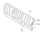
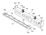
図2及び図4〜図7に示すように内側ガイド73の上面73bには2つの凹部73cが形成され、内側ガイド73両側の側壁73eからはそれぞれの軸73aが突出している。
As shown in FIGS. 2 and 4 to 7, two
また、支持フレーム81の底面81aには2つの凹部81bが形成され、支持フレーム81両側の側壁81cが底面81a側に突出し、これらの側壁81cに軸受け孔81dが形成されている。
In addition, two
内側ガイド73両側の軸73aが支持フレーム81両側の軸受け孔81dに差し込まれて、内側ガイド73と支持フレーム81が連結されている。また、内側ガイド73の上面73bの各凹部73cと支持フレーム81の底面81aの各凹部81bに2つのコイルバネ82が嵌められ、各凹部73cと各凹部81bの内側にそれぞれのコイルバネ82が覆い隠されるようになっている。
The
次に、内側ガイド73及び支持フレーム81の組立手順を説明する。まず、図6に示すように支持フレーム81の底面81aの2つの凹部81bに、2つのコイルバネ82の一端側を嵌め入れて支持する。
Next, the assembly procedure of the
そして、図6及び図7に示すように内側ガイド73両側の軸73aを支持フレーム81両側の側壁81cの軸受け孔81dに挿入する。内側ガイド73両側の軸73aは、円柱の両側を削った平板状のものである。また、支持フレーム81両側の側壁81cの軸受け孔81dには切り欠き81eがあって、この切り欠き81eの開口幅が内側ガイド73の軸73aの平板状部分の厚みよりも僅かに広くされている。このため、図7に示すように内側ガイド73両側の軸73aを両側の軸受け孔81dの切り欠き81eに通すことができる。引き続いて、内側ガイド73を軸73a周りで90度回転させて、内側ガイド73の軸73aを両側の軸受け孔81dから外れないようにする。このとき、内側ガイド73の上面73bが支持フレーム81の底面81aに重なり合って対向し、2つのコイルバネ82の他端側が内側ガイド73の上面73bの各凹部73cに嵌り込む。
Then, as shown in FIGS. 6 and 7, the
この状態では、各コイルバネ82の一端側が支持フレーム81の底面81aの各凹部81bに嵌って支持され、各コイルバネ82の他端側が内側ガイド73の上面73bの各凹部73cに嵌って支持されている。
In this state, one end side of each
この後、図4に示すように支持フレーム81両側の側壁81cの軸受け孔81dの切り欠き81eを外側ガイド72側に向け、ビスを用いて、支持フレーム81を外側ガイド72に取り付けて固定する。このとき、図2に示すように内側ガイド73が外側ガイド72側のストッパー74に当接して、支持フレーム81及び内側ガイド73と外側ガイド72間に隙間が形成され、この隙間がシート搬送経路Sとなる。また、内側ガイド73が軸73a周りで反時計回り方向に回転して変位し得るように、内側ガイド73の上面73bと支持フレーム81の底面81aとの間に内側ガイド73の逃げスペースQが形成される。
Thereafter, as shown in FIG. 4, the
このように支持フレーム81を外側ガイド72に取り付けた状態では、各コイルバネ82が支持フレーム81の底面81aの各凹部81b及び内側ガイド73の上面73bの各凹部73cに嵌って支持される。換言すれば、各コイルバネ82の殆どの部分が、支持フレーム81の各凹部81b及び内側ガイド73の各凹部73cの内側に囲まれ、各凹部81bの側壁81f及び各凹部73cの側壁73dにより覆い隠される。このため、装置本体Aの側壁83が開かれて、シート搬送経路S並びに内側ガイド73周辺が開放されても、各コイルバネ82が露見することはなく、不注意な作業等により各コイルバネ82が取り外されたり、各コイルバネ82そのものが壊されたりすることがない。
Thus, in a state where the
また、各コイルバネ82の一端側を支持フレーム81の底面81aの2つの凹部81bに嵌め入れ、内側ガイド73両側の軸73aを支持フレーム81両側の側壁81cの軸受け孔81dに挿入し、内側ガイド73を回転移動させて、内側ガイド73の上面73bと支持フレーム81の底面81aを対向させ、各コイルバネ82を支持フレーム81の各凹部81b及び内側ガイド73の各凹部73cの内側に配置するようにしているので、各コイルバネ82を組み込むための作業が簡単かつ容易である。
Further, one end of each
更に、支持フレーム81を外側ガイド72に取り付けた状態では、支持フレーム81両側の軸受け孔81dの切り欠き81eが外側ガイド72側に向くので、切り欠き81eから外す方向への内側ガイド73の軸73aの移動が禁止された状態となり、内側ガイド73の着脱が不可能になる。これにより、各コイルバネ82の取り外しが困難になる。
Further, in a state where the
以上、添付図面を参照しながら本発明の好適な実施形態について説明したが、本発明は係る例に限定されないことは言うまでもない。当業者であれば、特許請求の範囲に記載された範疇内において、各種の変更例または修正例に想到し得ることは明らかであり、それらについても当然に本発明の技術的範囲に属するものと解される。 As mentioned above, although preferred embodiment of this invention was described referring an accompanying drawing, it cannot be overemphasized that this invention is not limited to the example which concerns. It will be apparent to those skilled in the art that various changes and modifications can be made within the scope of the claims, and these are naturally within the technical scope of the present invention. It is understood.
A 画像形成装置
B 原稿読取り装置
S 用紙搬送経路
1(1a、1b、1c、1d) レーザ露光装置
2(2a、2b、2c、2d) 現像装置
3(3a、3b、3c、3d) 感光体ドラム
4(4a、4b、4c、4d) クリーナ装置
5(5a、5b、5c、5d) 帯電器
7 中間転写ベルト
8 中間転写ベルト装置
10 給紙トレイ
11 2次転写装置
12 定着装置
14 レジストローラ
15 排紙トレイ
18、18A シート搬送装置
19 レジスト前ローラ
41 原稿セットトレイ
44 ピックアップローラ
53 第1走査部
54 第2走査部
55 結像レンズ
56 CCD
71 湾曲部
72 外側ガイド
73 内側ガイド
74 ストッパー
75 撓みスペース
81 支持フレーム
82 コイルバネ
A Image forming apparatus B Document reading apparatus S Paper conveyance path 1 (1a, 1b, 1c, 1d) Laser exposure apparatus 2 (2a, 2b, 2c, 2d) Developing apparatus 3 (3a, 3b, 3c, 3d) Photosensitive drum 4 (4a, 4b, 4c, 4d) Cleaner device 5 (5a, 5b, 5c, 5d)
71
Claims (3)
前記バネの一端側を支持するための凹部を前記ガイド部材に形成すると共に、該バネの他端側を支持するための凹部を該ガイド部材の支持部材に形成し、該ガイド部材の凹部と前記支持部材の凹部の内側に該バネを配置して囲い、該ガイド部材と該支持部材の間に該バネを挟み込んだことを特徴とするシート搬送装置。 In the sheet conveying apparatus in which the guide member forming a part of the sheet conveying path is elastically positioned by a spring and can open the vicinity of the guide member for maintenance of the apparatus.
A recess for supporting one end of the spring is formed in the guide member, and a recess for supporting the other end of the spring is formed in the support member of the guide member. A sheet conveying apparatus, wherein the spring is disposed and enclosed inside a concave portion of a support member, and the spring is sandwiched between the guide member and the support member.
前記バネの一端側又は他端側を該ガイド部材の凹部又は該支持部材の凹部に配置した後に、該ガイド部材を回転移動させて、該ガイド部材の凹部と該支持部材の凹部を対向させ、これらの凹部の内側に該バネを配置して囲ったことを特徴とする請求項1に記載のシート搬送装置。 The guide member is attached to the support member so as to be rotatable.
After one end or the other end of the spring is disposed in the recess of the guide member or the recess of the support member, the guide member is rotated and moved so that the recess of the guide member and the recess of the support member face each other. The sheet conveying apparatus according to claim 1, wherein the spring is disposed and enclosed inside the concave portions.
該支持部材を装置本体側に取り付けた状態では、該支持部材に対する該ガイド部材の着脱方向の移動が禁止されることを特徴とする請求項1に記載のシート搬送装置。 The guide member is detachably attached to the support member,
2. The sheet conveying apparatus according to claim 1, wherein in a state where the support member is attached to the apparatus main body side, movement of the guide member in the attaching / detaching direction with respect to the support member is prohibited.
Priority Applications (3)
| Application Number | Priority Date | Filing Date | Title |
|---|---|---|---|
| JP2008183939A JP4568354B2 (en) | 2008-07-15 | 2008-07-15 | Sheet transport device |
| US12/501,743 US8444143B2 (en) | 2008-07-15 | 2009-07-13 | Sheet transport apparatus |
| CN2009101594792A CN101628670B (en) | 2008-07-15 | 2009-07-14 | Sheet transport apparatus |
Applications Claiming Priority (1)
| Application Number | Priority Date | Filing Date | Title |
|---|---|---|---|
| JP2008183939A JP4568354B2 (en) | 2008-07-15 | 2008-07-15 | Sheet transport device |
Publications (2)
| Publication Number | Publication Date |
|---|---|
| JP2010023938A true JP2010023938A (en) | 2010-02-04 |
| JP4568354B2 JP4568354B2 (en) | 2010-10-27 |
Family
ID=41529602
Family Applications (1)
| Application Number | Title | Priority Date | Filing Date |
|---|---|---|---|
| JP2008183939A Active JP4568354B2 (en) | 2008-07-15 | 2008-07-15 | Sheet transport device |
Country Status (3)
| Country | Link |
|---|---|
| US (1) | US8444143B2 (en) |
| JP (1) | JP4568354B2 (en) |
| CN (1) | CN101628670B (en) |
Cited By (1)
| Publication number | Priority date | Publication date | Assignee | Title |
|---|---|---|---|---|
| WO2016194466A1 (en) * | 2015-05-29 | 2016-12-08 | 沖電気工業株式会社 | Conveyance guide, medium storage, and medium transaction apparatus |
Families Citing this family (3)
| Publication number | Priority date | Publication date | Assignee | Title |
|---|---|---|---|---|
| JP5124624B2 (en) * | 2010-08-04 | 2013-01-23 | シャープ株式会社 | Image reading apparatus and image forming apparatus |
| JP4982597B2 (en) * | 2010-08-25 | 2012-07-25 | シャープ株式会社 | Recording material conveying apparatus and image forming apparatus |
| JP2012180176A (en) * | 2011-03-01 | 2012-09-20 | Seiko Epson Corp | Medium transport apparatus, scanner apparatus, and recording apparatus |
Citations (4)
| Publication number | Priority date | Publication date | Assignee | Title |
|---|---|---|---|---|
| JPH03267226A (en) * | 1990-03-19 | 1991-11-28 | Fuji Xerox Co Ltd | Picture image forming device with multistage tray |
| JP2005138970A (en) * | 2003-11-07 | 2005-06-02 | Murata Mach Ltd | Reversal carrying passage in double-sided image forming device |
| JP2007131455A (en) * | 2005-10-13 | 2007-05-31 | Ricoh Co Ltd | Recording medium feeding device, scanner device, and image forming device |
| JP2007279414A (en) * | 2006-04-07 | 2007-10-25 | Murata Mach Ltd | Automatic document feeder and image forming apparatus |
Family Cites Families (14)
| Publication number | Priority date | Publication date | Assignee | Title |
|---|---|---|---|---|
| JPH0818740B2 (en) * | 1986-08-30 | 1996-02-28 | キヤノン株式会社 | Sheet ejection device |
| JPH02127333A (en) * | 1988-11-02 | 1990-05-16 | Minolta Camera Co Ltd | Sheet supply device |
| US5083766A (en) * | 1989-07-19 | 1992-01-28 | Nisca Corporation | Automatic sheet feeding device having a miniaturized structure |
| JP2814159B2 (en) * | 1992-01-31 | 1998-10-22 | キヤノン株式会社 | Paper discharge transport device |
| JPH0822607B2 (en) * | 1992-12-18 | 1996-03-06 | 日本電気株式会社 | Printer paper feed mechanism |
| JPH06191686A (en) * | 1992-12-24 | 1994-07-12 | Ricoh Co Ltd | Paper feeding device |
| JP3530543B2 (en) * | 1993-02-25 | 2004-05-24 | セイコーエプソン株式会社 | Cut sheet skew removal method and apparatus |
| JP3374571B2 (en) * | 1995-02-08 | 2003-02-04 | 富士ゼロックス株式会社 | Automatic document feeder |
| JP3238070B2 (en) * | 1996-04-16 | 2001-12-10 | ブラザー工業株式会社 | Printing device feeder |
| ATE512922T1 (en) * | 2000-05-17 | 2011-07-15 | Seiko Epson Corp | TRANSPORT UNIT FOR PRINT MEDIUM |
| JP2001341909A (en) * | 2000-06-05 | 2001-12-11 | Canon Inc | Sheet conveying device and image forming device |
| JP2005154100A (en) | 2003-11-27 | 2005-06-16 | Fuji Xerox Co Ltd | Sheet skew correction device |
| JP2005335823A (en) | 2004-05-24 | 2005-12-08 | Fuji Xerox Co Ltd | Paper carrying device |
| JP4279243B2 (en) | 2004-11-11 | 2009-06-17 | 富士通株式会社 | Laser diode adjustment fixing mechanism |
-
2008
- 2008-07-15 JP JP2008183939A patent/JP4568354B2/en active Active
-
2009
- 2009-07-13 US US12/501,743 patent/US8444143B2/en active Active
- 2009-07-14 CN CN2009101594792A patent/CN101628670B/en not_active Expired - Fee Related
Patent Citations (4)
| Publication number | Priority date | Publication date | Assignee | Title |
|---|---|---|---|---|
| JPH03267226A (en) * | 1990-03-19 | 1991-11-28 | Fuji Xerox Co Ltd | Picture image forming device with multistage tray |
| JP2005138970A (en) * | 2003-11-07 | 2005-06-02 | Murata Mach Ltd | Reversal carrying passage in double-sided image forming device |
| JP2007131455A (en) * | 2005-10-13 | 2007-05-31 | Ricoh Co Ltd | Recording medium feeding device, scanner device, and image forming device |
| JP2007279414A (en) * | 2006-04-07 | 2007-10-25 | Murata Mach Ltd | Automatic document feeder and image forming apparatus |
Cited By (2)
| Publication number | Priority date | Publication date | Assignee | Title |
|---|---|---|---|---|
| WO2016194466A1 (en) * | 2015-05-29 | 2016-12-08 | 沖電気工業株式会社 | Conveyance guide, medium storage, and medium transaction apparatus |
| JP2016222409A (en) * | 2015-05-29 | 2016-12-28 | 沖電気工業株式会社 | Conveyance guide, medium storage warehouse and medium transaction device |
Also Published As
| Publication number | Publication date |
|---|---|
| CN101628670B (en) | 2012-06-13 |
| JP4568354B2 (en) | 2010-10-27 |
| US20100013147A1 (en) | 2010-01-21 |
| CN101628670A (en) | 2010-01-20 |
| US8444143B2 (en) | 2013-05-21 |
Similar Documents
| Publication | Publication Date | Title |
|---|---|---|
| US9201387B2 (en) | Image forming apparatus | |
| US20080138110A1 (en) | Process cartridge and electrophotographic image forming apparatus | |
| JP5831048B2 (en) | Image forming apparatus | |
| US8439353B2 (en) | Sheet feeding device and image forming apparatus | |
| JP4568354B2 (en) | Sheet transport device | |
| JP4765431B2 (en) | Image forming apparatus | |
| JP4986952B2 (en) | Exchange unit and image forming apparatus | |
| JP5082235B2 (en) | Image forming apparatus | |
| JP2010271472A (en) | Image forming apparatus | |
| JP4485479B2 (en) | Fixing apparatus and image forming apparatus | |
| US8452206B2 (en) | Image-forming apparatus with improved positioning for medium conveyance | |
| JP6765806B2 (en) | Process cartridge, image forming device and separating member | |
| US9541894B2 (en) | Image forming apparatus including movable guide section movably supported by apparatus main body | |
| JP5746084B2 (en) | Image forming apparatus | |
| JP5031699B2 (en) | Opening / closing device and image forming apparatus having the same | |
| JP2007298709A (en) | Belt driving device and image forming device | |
| JP2010047351A (en) | Sheet conveying device and image forming device with the same | |
| JP2009256011A (en) | Sheet carrying device, and image forming apparatus having the same | |
| JP4937153B2 (en) | Image forming apparatus | |
| JP2008265950A (en) | Image forming device | |
| JP3689633B2 (en) | Process cartridge and image forming apparatus | |
| JP4428116B2 (en) | Sheet feeding unit, sheet conveying apparatus, and image forming apparatus | |
| JP6868955B2 (en) | Paper transport device and image forming device equipped with it | |
| JP5625090B2 (en) | Sheet material feeding apparatus and image forming apparatus | |
| JP2021176805A (en) | Image formation device |
Legal Events
| Date | Code | Title | Description |
|---|---|---|---|
| A977 | Report on retrieval |
Free format text: JAPANESE INTERMEDIATE CODE: A971007 Effective date: 20100423 |
|
| A131 | Notification of reasons for refusal |
Free format text: JAPANESE INTERMEDIATE CODE: A131 Effective date: 20100511 |
|
| A521 | Request for written amendment filed |
Free format text: JAPANESE INTERMEDIATE CODE: A523 Effective date: 20100618 |
|
| TRDD | Decision of grant or rejection written | ||
| A01 | Written decision to grant a patent or to grant a registration (utility model) |
Free format text: JAPANESE INTERMEDIATE CODE: A01 Effective date: 20100713 |
|
| A01 | Written decision to grant a patent or to grant a registration (utility model) |
Free format text: JAPANESE INTERMEDIATE CODE: A01 |
|
| A61 | First payment of annual fees (during grant procedure) |
Free format text: JAPANESE INTERMEDIATE CODE: A61 Effective date: 20100806 |
|
| R150 | Certificate of patent or registration of utility model |
Free format text: JAPANESE INTERMEDIATE CODE: R150 Ref document number: 4568354 Country of ref document: JP Free format text: JAPANESE INTERMEDIATE CODE: R150 |
|
| FPAY | Renewal fee payment (event date is renewal date of database) |
Free format text: PAYMENT UNTIL: 20130813 Year of fee payment: 3 |