JP2010023116A - Method for manufacturing cutting edge member of cutting tool and die for press forming of pressed powder body used in manufacturing method thereof - Google Patents

Method for manufacturing cutting edge member of cutting tool and die for press forming of pressed powder body used in manufacturing method thereof Download PDF

Info

Publication number
JP2010023116A
JP2010023116A JP2009251992A JP2009251992A JP2010023116A JP 2010023116 A JP2010023116 A JP 2010023116A JP 2009251992 A JP2009251992 A JP 2009251992A JP 2009251992 A JP2009251992 A JP 2009251992A JP 2010023116 A JP2010023116 A JP 2010023116A
Authority
JP
Japan
Prior art keywords
die
cavity
punch
green compact
punches
Prior art date
Legal status (The legal status is an assumption and is not a legal conclusion. Google has not performed a legal analysis and makes no representation as to the accuracy of the status listed.)
Granted
Application number
JP2009251992A
Other languages
Japanese (ja)
Other versions
JP5195717B2 (en
JP2010023116A5 (en
Inventor
Giichi Okada
義一 岡田
Current Assignee (The listed assignees may be inaccurate. Google has not performed a legal analysis and makes no representation or warranty as to the accuracy of the list.)
Mitsubishi Materials Corp
Original Assignee
Mitsubishi Materials Corp
Priority date (The priority date is an assumption and is not a legal conclusion. Google has not performed a legal analysis and makes no representation as to the accuracy of the date listed.)
Filing date
Publication date
Application filed by Mitsubishi Materials Corp filed Critical Mitsubishi Materials Corp
Priority to JP2009251992A priority Critical patent/JP5195717B2/en
Publication of JP2010023116A publication Critical patent/JP2010023116A/en
Publication of JP2010023116A5 publication Critical patent/JP2010023116A5/ja
Application granted granted Critical
Publication of JP5195717B2 publication Critical patent/JP5195717B2/en
Anticipated expiration legal-status Critical
Expired - Lifetime legal-status Critical Current

Links

Images

Abstract

<P>PROBLEM TO BE SOLVED: To form a pressed powder body for a vertical edge type throwaway chip with a chip breaker projected from the rake face, for example, by making punches advance or separate in the thickness direction of the chip body. <P>SOLUTION: A die for press forming of pressed powder is provided with punches 21 and 22 which mutually face and are relatively made to advance or separate and a die 24 defining a cavity 23 surrounding the periphery of the punches 21 and 22. The die is used to perform press forming of a pressed powder body by pressurizing material powder put into the cavity 23, with punches 21 and 22. A concave part 26 which recedes towards the outside of the cavity 23 is formed in the die 24 and material powder to be pressed by punches 21 and 22 is closely filled in the concave part 26, so that a projecting portion which becomes convex relatively to a portion adjoining to the direction side where punches 21 and 22 are separated is formed in a portion of the pressed powder body which is formed by the die 24. <P>COPYRIGHT: (C)2010,JPO&INPIT

Description

本発明は、切刃を備えて切削工具の本体に着脱可能に装着されるスローアウェイチップのような切削工具の切刃部材の製造方法、およびこのような切刃部材を、その原料粉末を圧縮した圧粉体から製造する場合の該製造方法に用いられる圧粉体のプレス成形金型に関するものである。   The present invention relates to a method for manufacturing a cutting blade member of a cutting tool such as a throw-away tip that is provided with a cutting blade and is detachably attached to the main body of the cutting tool, and compresses the raw material powder of such a cutting blade member. The present invention relates to a green compact press-molding die used in the manufacturing method in the case of manufacturing from a green compact.

このような切削工具の切刃部材の製造方法としては、例えば特許文献1に上記スローアウェイチップの製造方法として、図19に示すような方形平板状のチップ本体1を備えて、その方形をなす平板面2の周囲に配置される4つの周面のうち、互いに反対側に位置する一対の周面がすくい面3とされ、このすくい面3と逃げ面とされる上記平板面2との交差稜線が切刃4とされた所謂縦刃式のスローアウェイチップの製造方法が提案されている。すなわち、この特許文献1記載の製造方法では、チップ本体1の厚さ方向(図19において上下方向)に対応する方向に垂直な方向に互いに対向して離接(上下動)する上下のパンチと、上下動して接近したこれら上下パンチの周囲を取り囲むように配設されて該上下パンチとの間にキャビティーを画成するダイとを備えたプレス成形金型を用いて、上記キャビティー内に投入した超硬合金等のスローアウェイチップの原料粉末を、上下パンチによって圧縮して圧粉体をプレス成形するようにしている。   As a manufacturing method of the cutting blade member of such a cutting tool, for example, as a manufacturing method of the above throwaway tip in Patent Document 1, a rectangular flat plate-shaped chip body 1 as shown in FIG. Of the four peripheral surfaces arranged around the flat plate surface 2, a pair of peripheral surfaces positioned on the opposite sides is a rake surface 3, and the rake surface 3 intersects the flat plate surface 2 as a flank surface. A so-called vertical blade type throw-away tip manufacturing method in which the ridge line is the cutting edge 4 has been proposed. That is, in the manufacturing method described in Patent Document 1, the upper and lower punches that are opposed to each other in the direction perpendicular to the direction corresponding to the thickness direction of the chip body 1 (up and down direction in FIG. 19) (up and down movement) Using a press molding die provided with a die which is arranged so as to surround the upper and lower punches which are moved up and down and which surrounds the upper and lower punches to define a cavity between the upper and lower punches. The raw powder of the throw-away tip such as cemented carbide introduced in is compressed by upper and lower punches, and the green compact is press-molded.

なお、上記スローアウェイチップにおいては、そのチップ本体1の上記周面のうちすくい面3に隣接する残りの一対の他の周面5と該すくい面3との交差稜線も切刃6として使用されることがあり、この場合にはこの他の周面5は該切刃6の逃げ面とされるるとともに、この他の周面5と上記平板面2との交差稜線部は断面1/4凸円弧等の凸曲面とされ、これに伴い上記切刃4,6が形成された交差稜線同士が交差するすくい面3の角部には、これらの切刃4,6に滑らかに連なる1/4凸円弧状のコーナ部7が形成される。また、この特許文献1に記載されたスローアウェイチップは、上記すくい面3と逃げ面とされる平板面2および他の周面5が切刃4,6を介して直交する方向に配設されたネガティブタイプとされ、しかも上記すくい面3にチップブレーカ8が形成されたブレーカ付きのスローアウェイチップとされている。さらに、この特許文献1では、上記キャビティー内にダイからピンを出没可能に設けて、スローアウェイチップの工具本体への取り付けの際にクランプネジ等が挿入される取付穴9となる貫通孔を圧粉体に形成するようにしている。   In the throw-away tip, the crossed ridge line between the other peripheral surface 5 adjacent to the rake face 3 of the peripheral surface of the tip body 1 and the rake face 3 is also used as the cutting edge 6. In this case, the other peripheral surface 5 is used as a flank of the cutting edge 6, and the cross ridge line portion between the other peripheral surface 5 and the flat plate surface 2 has a ¼ section. A convex curved surface such as a circular arc is formed, and at the corner portion of the rake face 3 where the intersecting ridgelines formed with the cutting edges 4 and 6 are intersected with each other, 1/4 is smoothly connected to the cutting edges 4 and 6. A convex arc-shaped corner portion 7 is formed. In addition, the throw-away tip described in Patent Document 1 is arranged in a direction in which the rake face 3 and the flat plate surface 2 and the other peripheral surface 5 serving as the flank face are orthogonal to each other via the cutting edges 4 and 6. Further, it is a throw-away tip with a breaker in which a chip breaker 8 is formed on the rake face 3. Further, in Patent Document 1, a pin is provided in the cavity so that the pin can be projected and retracted, and a through-hole serving as a mounting hole 9 into which a clamp screw or the like is inserted when the throw-away tip is attached to the tool body is provided. It is designed to form a green compact.

一方、特許文献2には、同じ切刃部材としてのスローアウェイチップではあるものの、上記縦刃式スローアウェイチップとは異なり、三角形平板状のチップ本体の厚さ方向を向く三角形の平板面がすくい面とされるとともに、この平板面の周りに配置される周面が逃げ面とされ、この逃げ面に凹入したアンダーカット部が形成された、いわゆるダブルポジティブタイプのスローアウェイチップの製造方法およびその圧粉体のプレス成形金型が記載されている。すなわち、この特許文献2では、チップ本体の厚さ方向に対応する方向に上下動する上下パンチと、その周囲を取り囲んでキャビティーを画成するダイとを備えたプレス成形金型を用いて、このダイを複数に分割して上記チップ本体の厚さ方向に対応する方向に垂直な方向に進退可能とするとともに、これらの分割したダイのキャビティーを形成する面部分には突起部を設け、この突起部によって上記アンダーカット部に対応する部分を圧粉体の周面に成形するようにしている。なお、これらのプレス成形金型によって成形された圧粉体は、焼結されて上記スローアウェイチップに製造される。   On the other hand, in Patent Document 2, although it is a throw-away tip as the same cutting blade member, unlike the above-described vertical-blade type throw-away tip, a triangular flat plate surface facing the thickness direction of the triangular flat plate tip body is scooped. A method of manufacturing a so-called double positive type throw-away tip, in which a peripheral surface disposed around the flat plate surface is used as a flank, and an undercut portion recessed in the flank is formed. The green compact press mold is described. That is, in this Patent Document 2, using a press mold having a vertical punch that moves up and down in a direction corresponding to the thickness direction of the chip body, and a die that surrounds the periphery and defines a cavity, The die is divided into a plurality of pieces so as to be able to advance and retreat in a direction perpendicular to the direction corresponding to the thickness direction of the chip body, and a protrusion is provided on a surface portion forming a cavity of these divided dies, A portion corresponding to the undercut portion is formed on the peripheral surface of the green compact by the protrusion. The green compact molded by these press molds is sintered and manufactured to the above-mentioned throw-away tip.

特開平10−146695号公報Japanese Patent Laid-Open No. 10-146695 特開平10−71497号公報Japanese Patent Laid-Open No. 10-71497

ところで、上記特許文献1に記載のように縦刃式スローアウェイチップに形成される圧粉体を、特許文献2と同様にチップ本体の厚さ方向に対応する方向に対向して離接する上下パンチと、その周囲を取り囲んでキャビティーを画成するダイとを備えたプレス成形金型を用いて成形しようとして、圧粉体の凸曲面となる交差稜線部を、上下パンチのプレス面によって成形しようとすると、これらのプレス面のダイ側の摺接面と摺接するパンチ側の摺接面の周縁部には、この凸曲面に合わせた凹曲面状をなすエッジ部が形成されることとなって、このエッジ部は先端に向かうほどその交差角が限りなく鋭くなるため、容易に欠けなどの破損が生じ易くなってしまう。 By the way, the upper and lower punches that contact and separate the green compact formed on the vertical blade type throwaway tip as described in Patent Document 1 in the direction corresponding to the thickness direction of the chip body as in Patent Document 2. Then, try to mold using a press mold that includes a die that surrounds the die and defines a cavity . Then, an edge portion having a concave curved surface shape that matches the convex curved surface is formed on the peripheral edge portion of the sliding surface on the punch side that is in sliding contact with the sliding surface on the die side of these press surfaces. Since the edge portion of the edge portion becomes sharper as it goes toward the tip, breakage such as chipping is easily generated.

本発明は、このような背景の下になされたもので、互いに対向して離接する上下パンチとその周囲に配置されてキャビティーを画成するダイとを備えたプレス成形金型を用いて、例えば縦刃式スローアウェイチップのような切削工具の切刃部材を、このスローアウェイチップのチップ本体の厚さ方向に対応する方向に上記パンチを離接させて該切刃部材に製造される圧粉体を成形することにより製造するのに際して、上述のような破損を防いでプレス成形金型の寿命の延長を図ることが可能な切削工具の切刃部材の製造方法を提供し、またかかる製造方法に用いて好適な圧粉体のプレス成形金型を提供することを目的としている。 The present invention is made under such a background, using a press mold having an upper and lower punches that are opposed to each other and a die that is arranged around the upper and lower punches to define a cavity, For example, a cutting blade member of a cutting tool such as a vertical blade type throwaway tip is pressed against the punch body in a direction corresponding to the thickness direction of the tip body of the throwaway tip, and the pressure produced on the cutting blade member. Provided is a method for manufacturing a cutting tool member of a cutting tool capable of preventing damage as described above and extending the life of a press mold when manufacturing by molding powder, and manufacturing the same It is an object of the present invention to provide a green compact press mold suitable for use in the method.

上記課題を解決して、このような目的を達成するために、本発明の切削工具の切刃部材の製造方法は、互いに対向して相対的に離接させられるパンチと、接近したこれらパンチの周囲を取り囲むように配設されて該パンチとの間にキャビティーを画成するダイとを備えたプレス成形金型を用いて、上記キャビティーに投入した超硬合金またはサーメットの原料粉末を上記パンチによって圧縮することにより、切削工具の切刃を備えた切刃部材に製造される圧粉体をプレス成形する切削工具の切刃部材の製造方法であって、上記ダイを、上記キャビティーを間にして上記パンチの離接方向または該離接方向に垂直な方向に分割して駆動手段によって離接可能とするとともに、上記ダイに上記キャビティーの外側に向けて後退する凹部を形成し、上記パンチの離接方向を向くこの凹部の壁面を、該凹部の底面と圧縮時の上記パンチのプレス面とに鈍角に交差するように連なる平面状に形成して、この凹部に上記パンチによって圧縮される上記原料粉末を充密させることにより、上記圧粉体において上記ダイにより成形される部分に、面取り状の平面を有して上記パンチが離間する方向側に隣接する部分に対して相対的に凸となる突出部を成形することを特徴とする。 In order to solve the above-described problems and achieve such an object, a manufacturing method of a cutting blade member of a cutting tool according to the present invention includes a punch that is relatively opposed to and separated from each other, and a punch that is close to each other. A cemented carbide or cermet raw material powder charged into the cavity is formed using a press molding die provided with a die that is disposed so as to surround the periphery and that defines a cavity with the punch. A method for producing a cutting tool member of a cutting tool, wherein the green compact produced on the cutting blade member provided with the cutting edge of the cutting tool is pressed by a punch, wherein the die is inserted into the cavity. thereby enabling disjunctive by dividing the drive means in a direction perpendicular to the disjunction direction or該離contact direction of the punch in between, a recess receding toward the outside of the cavity in the die, The wall of the recess facing the disjunction direction of serial punch, formed in a planar shape continuous to intersect at an obtuse angle to the pressing surface of the punch during compression and the bottom surface of the recess, compressed by the punch into the recess By filling the raw material powder, the portion of the green compact formed by the die has a chamfered plane and is relative to the portion adjacent to the side in which the punch is separated. A protruding portion that is convex is formed.

また、本発明の圧粉体のプレス成形金型は、このようなスローアウェイチップの製造方法に用いられる圧粉体のプレス成形金型であって、互いに対向して相対的に離接させられるパンチと、接近したこれらパンチの周囲を取り囲むように配設されて該パンチとの間にキャビティーを画成するダイとを備え、上記ダイは、上記キャビティーを間にして上記パンチの離接方向または該離接方向に垂直な方向に分割されて駆動手段によって離接可能とされるとともに、このダイには、上記キャビティーの外側に向けて後退する凹部が形成されていて、上記パンチの離接方向を向くこの凹部の壁面が、該凹部の底面と圧縮時の上記パンチのプレス面とに鈍角に交差するように連なる平面状に形成されていることを特徴とする。 The green compact press-molding die of the present invention is a green compact press-molding die used in such a throw-away chip manufacturing method, and is opposed to and relatively separated from each other. A punch, and a die disposed so as to surround the adjacent punches and defining a cavity between the punches, wherein the die is separated from and attached to the punch with the cavity interposed therebetween. The die is divided into a direction or a direction perpendicular to the separation / contact direction and can be separated / attached by the driving means, and the die is formed with a recess that recedes toward the outside of the cavity . A wall surface of the concave portion facing the separation / contact direction is formed in a planar shape that is connected to the bottom surface of the concave portion and the press surface of the punch during compression so as to intersect an obtuse angle .

このような切削工具の切刃部材の製造方法および該製造方法に用いられる圧粉体のプレス成形金型では、キャビティーを画成するプレス成形金型のダイに、このキャビティーの外側に向けて後退する凹部が形成されていることにより、キャビティーに投入された原料粉末は、パンチの接近によって圧縮される際にパンチの離接方向からはみ出すように押し出されることによって該凹部に充密され、圧縮されて上記突出部に成形されることとなる。従って、この切刃部材が、略平板状を呈するチップ本体を有して、該チップ本体の厚さ方向を向く平板面とこの平板面の周りに配置される周面とを備え、この周面に形成されたすくい面と上記平板面との交差稜線と、このすくい面に隣接する他の周面と該すくい面との交差稜線との少なくとも一方に切刃が形成された上記縦刃式のスローアウェイチップであってこのような圧粉体を上記チップ本体の厚さ方向に対応する方向に上記パンチを離接することにより成形する場合に、突出部が圧粉体においてチップ本体の例えば逃げ面に対応する他の周面に対応する部分に成形されるように上記凹部をダイ側に形成することにより、パンチのプレス面とパンチ側の摺接面との交差角は直角を確保することができるので、このような破損を防いでプレス成形金型の寿命の延長を図ることができる。そして、さらに上記凹部の壁面を、該凹部の底面と圧縮時の上記パンチのプレス面とに鈍角に交差するように連なる平面状に形成することにより、チップ本体の交差稜線部が面取り状の平面とされてチャンファ状に形成されたスローアウェイチップを製造することができる。 In the manufacturing method of the cutting blade member of such a cutting tool and the press molding die of the green compact used in the manufacturing method, the die of the press molding die that defines the cavity faces the outside of the cavity. By forming a recess that recedes, the raw material powder charged into the cavity is packed into the recess by being pushed out of the punch contact direction when compressed by the approach of the punch. Then, it is compressed and molded into the protruding portion. Accordingly, the cutting blade member has a chip body having a substantially flat plate shape, and includes a flat plate surface facing the thickness direction of the chip main body and a peripheral surface arranged around the flat plate surface. The above-mentioned vertical blade type in which a cutting edge is formed on at least one of an intersecting ridge line between the rake face formed on the flat plate surface and another peripheral surface adjacent to the rake face and the rake face. a throw-away tip, such green compact when molding by detaching the punch in the direction corresponding to the thickness direction of the chip body, for example, relief of the chip body protrusions in compact By forming the concave portion on the die side so as to be molded in a portion corresponding to the other peripheral surface corresponding to the surface, the crossing angle between the press surface of the punch and the sliding contact surface on the punch side should be secured at a right angle. To prevent such damage. It is possible to extend the scan molding die life. Further, by forming the wall surface of the concave portion into a planar shape that is continuous with the bottom surface of the concave portion and the press surface of the punch during compression so as to intersect at an obtuse angle, the cross ridge line portion of the chip body is a chamfered flat surface. Thus, a throw-away tip formed in a chamfer shape can be manufactured.

また、このように上記切刃部材が平板状のスローアウェイチップであって、上記パンチがそのチップ本体の厚さ方向に対応する方向に離接させられる場合には、特許文献1記載の製造方法およびプレス成形金型のようにこの厚さ方向に対応する方向に垂直な方向にパンチが離接して圧粉体を成形するのに比べ、原料粉末を均一に圧縮することができるので、製造されたスローアウェイチップのチップ本体の変形を防いで、上記縦刃式のスローアウェイチップを製造する場合でも精度の向上を図ることができる。特に、この特許文献1記載では、図19に示したようにチップ本体1をその厚さ方向に貫通する取付穴9を形成するため、この厚さ方向に対応する方向、すなわちパンチの離接方向に垂直な方向にピンをキャビティー内に出没可能に設けて圧粉体に貫通孔を成形するようにしており、原料粉末の圧縮時にこのピンの周りで圧縮比が僅かながら変化してしまうことにより、製造されたスローアウェイチップにおいてもその取付穴9の周囲で微小な変形が生じるおそれがあるが、上述のようにパンチがチップ本体の厚さ方向に対応する方向に離接させられる場合には、上記キャビティー内に、互いに接近したこれらパンチ間に上記離接方向に突出する上記ピン等の突部を設けることにより、この突部の周囲での原料粉末の圧縮比の変化を抑えつつ圧粉体に貫通孔を成形することができ、チップ本体における取付穴周辺の変形を防ぐことができる。   Further, in the case where the cutting blade member is a flat throw-away tip and the punch is separated from the tip body in the direction corresponding to the thickness direction of the tip body, the manufacturing method described in Patent Document 1 Compared to forming a green compact by pressing and separating the punch in a direction perpendicular to the direction corresponding to the thickness direction as in the press molding die, the raw material powder can be compressed uniformly. Further, it is possible to prevent the tip body of the throwaway tip from being deformed and to improve the accuracy even when the vertical blade type throwaway tip is manufactured. In particular, in Patent Document 1, since the mounting hole 9 is formed so as to penetrate the chip body 1 in the thickness direction as shown in FIG. 19, the direction corresponding to the thickness direction, that is, the direction of attaching / detaching the punch A pin is provided in the cavity so that it can be projected and retracted in the direction perpendicular to the hole, and a through hole is formed in the green compact. When the raw material powder is compressed, the compression ratio changes slightly around this pin. As a result, there is a possibility that minute deformation may occur around the mounting hole 9 in the manufactured throw-away tip, but as described above, when the punch is moved away from and in the direction corresponding to the thickness direction of the tip body. In the cavity, a protrusion such as the pin protruding in the separating direction is provided between the punches that are close to each other while suppressing a change in the compression ratio of the raw material powder around the protrusion. Can be molded through holes in the powder, it is possible to prevent deformation around the mounting hole in the chip body.

ここで、このようにプレス成形金型のダイ側に、キャビティー外側に向けて後退する凹部を形成する場合、この凹部に充密されて突出部を成形する原料粉末は、上記パンチによる圧縮力に基づいて上述のように上記離接方向からはみ出すように該凹部に押し込まれて圧縮されるものであるから、この凹部の深さが、こうして原料粉末を押し込む圧縮力を作用させる凹部の上記離接方向の間隔に対して大きすぎると、原料粉末の圧縮の際に該凹部の奥にまで原料粉末が確実に行き渡らなかったり、あるいは該凹部内で原料粉末が十分に圧縮されなくなったりするおそれが生じる。このため、上記凹部の深さは、上記パンチの離接方向を向くこの凹部の両壁面に連なって上記キャビティーの内側に向けて凸となるその突端からの深さとして、これらの突端間の上記離接方向の間隔以下とされるのが望ましく、より望ましくはこの間隔の50%以下、さらに望ましくは25%以下とされる。   Here, in the case where a concave portion that recedes toward the outside of the cavity is formed on the die side of the press molding die in this way, the raw material powder that is packed in the concave portion and forms the protruding portion is compressed by the punch. As described above, the depth of the recess is compressed by being pushed into the recess so as to protrude from the separation / contact direction as described above. If the gap is too large with respect to the interval in the tangential direction, the raw material powder may not reach the back of the recess when the raw material powder is compressed, or the raw material powder may not be sufficiently compressed in the recess. Arise. For this reason, the depth of the concave portion is defined as the depth from the protruding end that protrudes toward the inside of the cavity and is continuous with both wall surfaces of the concave portion that faces the separation / contact direction of the punch. It is desirable that the distance be equal to or smaller than the distance in the separation direction, more desirably 50% or less, and even more desirably 25% or less of the distance.

なお、この凹部の上記離接方向を向く両壁面に連なってキャビティー内側に凸となるその突端は、キャビティーが画成されるときに上記離接方向に接近するパンチと摺接するダイ側の摺接面に対し、この凹部が全体的にキャビティー外側に後退している場合には当該ダイ側摺接面と凹部の壁面とが交わる部分そのものとなって、両突端間の上記間隔も凹部自体の上記離接方向におけるダイ側摺接面への開口幅となる Note that the projecting end of the concave portion that protrudes toward the inside of the cavity connected to both wall surfaces of the concave portion facing the separation direction is located on the die side that is in sliding contact with the punch that approaches the separation direction when the cavity is defined. When the concave portion is entirely retracted to the outside of the cavity with respect to the sliding contact surface, the die-side sliding contact surface and the wall surface of the concave portion itself become a portion itself, and the above-described distance between the two protruding ends is also the concave portion. It becomes the opening width to the die side sliding contact surface in the above-described separation / contact direction .

本発明のプレス成形金型を説明する上での第1の参考例を示す断面図である。It is a cross-sectional view showing the first reference example in order to explain the press-molding die of the present invention. 図1に示す参考例のダイ側摺接面24Cの拡大断面図である。It is an expanded sectional view of the die side sliding contact surface 24C of the reference example shown in FIG. 図1に示す参考例のダイ24の分割例を示すパンチ離接方向に見た平面図である。It is the top view seen in the punch separation / contact direction which shows the division example of the die | dye 24 of the reference example shown in FIG. 図1に示す参考例のプレス成形金型を用いた製造方法によって製造される縦刃式のスローアウェイチップの斜視図である。FIG. 2 is a perspective view of a vertical blade type throw-away tip manufactured by a manufacturing method using the press-molding die of the reference example shown in FIG. 1. 図1に示す参考例の変形例を示す断面図である。It is sectional drawing which shows the modification of the reference example shown in FIG. 図5に示す変形例のダイ側摺接面24Cの拡大断面図である。FIG. 6 is an enlarged cross-sectional view of a die side sliding contact surface 24C of the modification shown in FIG. 5. 図1に示す参考例の他の変形例を示す断面図である。It is sectional drawing which shows the other modification of the reference example shown in FIG. 図7に示す変形例のダイ側摺接面24Cの拡大断面図である。FIG. 8 is an enlarged cross-sectional view of a die side sliding contact surface 24 </ b> C of the modified example shown in FIG. 7. 本発明のプレス成形金型を説明する上での第2の参考例を示す断面図である。The second reference example in describing the press forming die of the present invention is a cross-sectional view illustrating. 図9に示す第2の参考例のプレス成形金型を用いた製造方法によって製造される縦刃式のスローアウェイチップの斜視図である。FIG. 10 is a perspective view of a vertical blade type throw-away tip manufactured by a manufacturing method using the press mold of the second reference example shown in FIG. 9. 本発明のプレス成形金型を説明する上での第3の参考例を示す断面図である。It is a sectional view showing a third reference example in describing the press forming die of the present invention. 本発明のプレス成形金型を説明する上での第4の参考例を示す断面図である。It is a sectional view showing a fourth reference example in describing the press forming die of the present invention. 図12に示す参考例のダイ側摺接面24Cの拡大断面図である。FIG. 13 is an enlarged cross-sectional view of a die side sliding contact surface 24 </ b> C of the reference example shown in FIG. 12. 図12に示す第4の参考例のプレス成形金型を用いた製造方法によって製造される縦刃式のスローアウェイチップの斜視図である。FIG. 13 is a perspective view of a vertical blade type throw-away tip manufactured by a manufacturing method using the press-molding die of the fourth reference example shown in FIG. 12. 本発明のプレス成形金型を説明する上での第5の参考例を示す断面図である。A fifth reference example in describing the press forming die of the present invention is a cross-sectional view illustrating. 三角形平板状の縦刃式スローアウェイチップを示す平面図である。It is a top view which shows a triangular flat plate type vertical blade type throwaway tip. 図16に示すスローアウェイチップの側面図である。It is a side view of the throw away tip shown in FIG. 本発明のプレス成形金型を説明する上での第6の参考例を示す断面図である。It is a sectional view showing a sixth reference example in describing the press forming die of the present invention. 方形平板状の縦刃式スローアウェイチップを示す斜視図である。It is a perspective view showing a rectangular flat plate type vertical blade type throwaway tip.

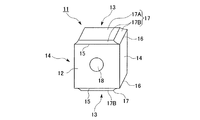
図1ないし図3は、本発明のプレス成形金型を説明する上での第1の参考例を示すものであり、図4は、かかるプレス成形金型を用いた切削工具の切刃部材の製造方法の一参考例により製造される切刃部材を示すものである。ここで、この切刃部材は、上述した縦刃式のスローアウェイチップであって、すなわち略方形平板状のチップ本体11を有し、このチップ本体11の厚さ方向(図4において左手前から右奥に向かう方向)を向いて方形をなす一対の平板面12と、この平板面12の周りに配置される4つの周面とを備え、これらの周面のうち、互いに反対側に位置する一対の周面(図4において上下の周面)がすくい面13とされるとともに、このすくい面13と上記平板面12との交差稜線、および該すくい面13と残りの一対の他の周面(図4において左右の周面)14との交差稜線にそれぞれ切刃15,16が形成されていて、上記平板面12および他の周面14がそれぞれこれら切刃15,16に対する逃げ面とされている。 FIGS. 1 to 3 show a first reference example for explaining the press molding die of the present invention. FIG. 4 shows a cutting blade member of a cutting tool using such a press molding die. The cutting blade member manufactured by one reference example of a manufacturing method is shown. Here, the cutting blade member is the above-described vertical blade type throw-away tip, that is, has a substantially rectangular flat plate-like tip body 11, and the thickness direction of the tip body 11 (from the left front side in FIG. 4). A pair of flat plate surfaces 12 having a square shape facing in the right back direction, and four peripheral surfaces arranged around the flat plate surface 12, and these peripheral surfaces are positioned on opposite sides of each other. A pair of peripheral surfaces (upper and lower peripheral surfaces in FIG. 4) serve as a rake face 13, a cross ridge line between the rake face 13 and the flat plate surface 12, and the rake face 13 and the remaining pair of other peripheral faces. Cutting edges 15 and 16 are formed on the intersecting ridge lines with the left and right peripheral surfaces in FIG. 4, respectively, and the flat plate surface 12 and the other peripheral surfaces 14 are flank surfaces for these cutting blades 15 and 16, respectively. ing.

そして、上記すくい面13には、その周縁の切刃15,16から該すくい面13の内側に向かうに従い漸次隆起するようにして上記チップ本体11の厚さ方向に垂直な方向に突出する突出部17が形成されており、上記切刃15,16のチップブレーカとされている。ここで、この突出部17の突端は上記平板面12および他の周面14に垂直でチップ本体11の厚さ方向に沿ったすくい面13より一回り小さな長方形の平坦面17Aとされるとともに、この平坦面17Aと切刃15,16との間は、該切刃15,16に直交する断面が凹円弧等をなすような凹曲面状とされて、切刃15,16から離間するに従い漸次隆起するブレーカ壁面17Bとされている。さらに、このチップ本体11には、上記一対の平板面12の中央に開口して該チップ本体11をその上記厚さ方向に貫通するチップ取付穴18が形成されている。   The rake face 13 protrudes in a direction perpendicular to the thickness direction of the chip body 11 so as to gradually rise from the peripheral cutting edges 15 and 16 toward the inside of the rake face 13. 17 is formed as a chip breaker for the cutting blades 15 and 16. Here, the projecting end of the projecting portion 17 is a rectangular flat surface 17A which is perpendicular to the flat plate surface 12 and the other peripheral surface 14 and is slightly smaller than the rake surface 13 along the thickness direction of the chip body 11. The flat surface 17A and the cutting blades 15 and 16 are formed in a concave curved surface in which a cross section perpendicular to the cutting blades 15 and 16 forms a concave arc or the like, and gradually as the distance from the cutting blades 15 and 16 increases. The breaker wall surface 17B is raised. Further, the chip body 11 is formed with a chip attachment hole 18 that opens in the center of the pair of flat plate surfaces 12 and penetrates the chip body 11 in the thickness direction.

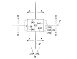
このような切刃部材としてのスローアウェイチップを製造するための参考例のプレス成形金型は、図1に示すように、互いに対向して図示されない駆動手段により相対的に離接させられる上下のパンチ21,22と、接近したこれらパンチ21,22の周囲を取り囲むように配設されて該パンチ21,22との間にキャビティー23を画成するダイ24とを備えている。ここで、これら上下パンチ21,22が互いに離接する方向(図1および図2において上下方向。以下、パンチ離接方向と称する。)はチップ本体11の厚さ方向に対応する方向に一致させられており、上パンチ21の下面と下パンチ22の上面とは、それぞれ上記チップ本体11の平板面12に対応する圧粉体の平板面を成形するプレス面21A,22Aとされていて、これらのプレス面21A,22Aは上記パンチ離接方向に垂直な平坦面とされている。 As shown in FIG. 1, the press-molding die of the reference example for manufacturing such a throw-away tip as a cutting blade member has upper and lower surfaces opposed to each other by driving means (not shown) facing each other. Punches 21 and 22 and a die 24 that is disposed so as to surround the adjacent punches 21 and 22 and that defines a cavity 23 between the punches 21 and 22 are provided. Here, the upper and lower punches 21, 22 mutually separating direction (vertical direction in FIGS. Hereinafter referred to as punch disjunction direction.) Is to match the direction corresponding to the thickness direction of the chip body 11 The lower surface of the upper punch 21 and the upper surface of the lower punch 22 are press surfaces 21A and 22A for forming a flat plate surface of the green compact corresponding to the flat plate surface 12 of the chip body 11, respectively. The press surfaces 21A and 22A are flat surfaces perpendicular to the punch separation / contact direction.

また、上記ダイ24は図1および図3に矢線Aで示すようにパンチ離接方向に垂直な一方向(図1および図3においては左右方向。以下、水平方向と称する。)に、上記キャビティー23を間にしてその略中央から図3に示す分割面Pを介して2分割される分割ダイ24A,24Bとから構成されていて、これら分割ダイ24A,24Bはやはり図示されない駆動手段によって上記水平方向に相対的に離接可能とされている。そして、これら分割ダイ24A,24Bが接近して密着することによってダイ24が形成されるとともに、下パンチ22がそのパンチ側摺接面22Bをこのダイ24のダイ側摺接面24Cに摺接させて該ダイ24に嵌挿され、次いで上側からは上パンチ21がそのパンチ側摺接面21Bをダイ側摺接面24Cに摺接させつつ下降して該ダイ24に嵌挿され、図1に示すようにキャビティー23が画成される(ただし、図においては説明のため、これらパンチ側摺接面21B,22Bとダイ側摺接面24Cとの間には大きな隙間があけられているが、実際にはこの隙間は数ミクロン程度である。)。なお、これらパンチ側、ダイ側摺接面21B,22B,24Cはいずれもパンチ離接方向に平行に延びる平坦面とされている。 Further, the die 24, (the left-right direction. The following 1 and 3, referred to as a horizontal direction.) A direction perpendicular to the punch disjunction direction as indicated by arrow line A in FIG. 1 and FIG. 3, The die 23 is divided into two dies 24A and 24B which are divided into two through the dividing surface P shown in FIG. 3 with the cavity 23 in between, and the dividing dies 24A and 24B are also not shown. Therefore, it is possible to make a relative separation in the horizontal direction. Then, the divided dies 24A and 24B come close to each other and come into close contact with each other to form the die 24, and the lower punch 22 slides the punch side sliding contact surface 22B on the die side sliding contact surface 24C of the die 24. Then, from above, the upper punch 21 descends while sliding the punch side sliding contact surface 21B against the die side sliding contact surface 24C, and is inserted into the die 24, as shown in FIG. As shown, a cavity 23 is defined (for the sake of illustration, a large gap is formed between the punch side sliding contact surfaces 21B and 22B and the die side sliding contact surface 24C. Actually, this gap is about several microns.) The punch side and die side sliding contact surfaces 21B, 22B, and 24C are all flat surfaces extending in parallel to the punch separation / contact direction.

さらに、こうして画成されるキャビティー23内には、互いに接近した上下パンチ21,22間にパンチ離接方向に突出するピン25が、チップ本体11の上記取付穴18となる貫通孔を圧粉体に成形するため突部として設けられている。すなわち、このピン25は円柱状をなしていて、下パンチ22上面のプレス面22A中央に開孔するように該下パンチ22に形成された円孔22C内に嵌挿され、やはり図示されない駆動手段により下パンチ22とは独立して上記プレス面22Aから上記パンチ離接方向にキャビティー23内に出没可能とされている。一方、上パンチ21には、その下面のプレス面21Aのやはりその中央に開孔する円孔21Cが形成されており、キャビティー23内に突出したピン25の先端(上端)部は、この上パンチ21の円孔21Cに嵌挿されて収容される。 Further, in the cavity 23 defined in this manner, a pin 25 protruding in the punch separation direction between the upper and lower punches 21, 22 that are close to each other, compresses the through hole that becomes the mounting hole 18 of the chip body 11. It is provided as a protrusion for molding on the body. That is, the pin 25 has a cylindrical shape, and is inserted into a circular hole 22C formed in the lower punch 22 so as to open at the center of the press surface 22A of the upper surface of the lower punch 22, and is also not shown. Thus, it is possible to move in and out of the cavity 23 from the press surface 22 </ b> A in the punch separation / contact direction independently of the lower punch 22. On the other hand, the upper punch 21 is formed with a circular hole 21C that opens at the center of the lower pressing surface 21A, and the tip (upper end) of the pin 25 protruding into the cavity 23 The punch 21 is received by being inserted into the circular hole 21 </ b> C.

そして、上記ダイ24には、パンチ21,22とによって画成されたキャビティー23に開口して該キャビティー23の外側に後退するように凹部26が形成されており、圧粉体においてチップ本体11のすくい面13に形成される突出部17に対応する部分は、この凹部26によって成形されることとなる。ここでこの凹部26は、分割ダイ24A,24Bの上記水平方向を向くダイ側摺接面24Cに対して後退するように形成されたものであって、その内面は、この水平方向に垂直とされてキャビティー23の内側を向く長方形平面状の底面26Aと、この底面26Aの4つの辺稜部から上記水平方向にキャビティー23の内側に向けて断面凸円弧等の凸曲面を描きつつ凹部26の開口部を拡げるように漸次隆起して上記ダイ側摺接面24Cに連なる壁面26Bとから構成されており、これら底面26Aおよび壁面26Bによって圧粉体における上記突出部17の平坦面17Aおよびブレーカ壁面17Bに対応する部分がそれぞれ成形される。 The die 24 is formed with a recess 26 so as to open to the cavity 23 defined by the punches 21 and 22 and to recede to the outside of the cavity 23. A portion corresponding to the protrusion 17 formed on the rake face 13 of the eleven is formed by the recess 26. Here, the concave portion 26 is formed so as to recede with respect to the die side sliding contact surface 24C facing the horizontal direction of the divided dies 24A and 24B, and the inner surface thereof is perpendicular to the horizontal direction. A rectangular flat bottom surface 26A facing the inside of the cavity 23, and a concave portion while drawing a convex curved surface such as a convex circular arc in a horizontal direction from the four side ridges of the bottom surface 26A toward the inside of the cavity 23. 26 is formed of a wall surface 26B that gradually rises so as to widen the opening of the die 26 and continues to the die-side sliding contact surface 24C. The flat surface 17A of the protrusion 17 in the green compact and the bottom surface 26A and the wall surface 26B Portions corresponding to the breaker wall surface 17B are respectively formed.

なお、この壁面26Bのうち、図1および図2に示されるダイ24の上記水平方向を向くダイ側摺接面24Cに連なる壁面26Bはこのダイ側摺接面24Cに滑らかに接して連なるように形成されており、キャビティー23を画成したときの上下パンチ21,22の上記プレス面21A,22Aの位置は、凸曲面を描くこれら壁面26Bと上記ダイ側摺接面24Cとの接線の位置とされている。一方、圧粉体においてチップ本体11の上記他の周面14に対応する周面を成形することとなるダイ側摺接面24Dは、パンチ離接方向に加えて上記水平方向にも平行に延びる平坦面とされ、このダイ側摺接面24Dに連なる凹部26の壁面26Bは、図3に破線で示すように上述のような突曲面を描きつつ該ダイ側摺接面24Dと角度をもって交差するように形成されており、キャビティー23を画成したときの上下パンチ21,22の上記プレス面21A,22Aのパンチ離接方向における位置は、この壁面26Bとダイ側摺接面24Dとの交差稜線の両端の位置とされる。 Incidentally, these wall 26B, wall 26B continuous with the die-side sliding contact surface 24C facing the horizontal direction of the die 24 shown in FIGS. 1 and 2, so as to continue smoothly in contact with the die-side sliding contact surface 24C The positions of the press surfaces 21A and 22A of the upper and lower punches 21 and 22 when the cavity 23 is defined are the tangents between the wall surface 26B describing the convex curved surface and the die side sliding contact surface 24C. It is considered as a position. On the other hand, the die side sliding contact surface 24D that forms the peripheral surface corresponding to the other peripheral surface 14 of the chip body 11 in the green compact extends in parallel to the horizontal direction in addition to the punch separation direction. The wall surface 26B of the recess 26 that is a flat surface and continues to the die-side sliding contact surface 24D intersects the die-side sliding contact surface 24D at an angle while drawing the above-described projecting curved surface as shown by a broken line in FIG. The positions of the upper and lower punches 21 and 22 in the punch separation direction of the upper and lower punches 21 and 22 when the cavity 23 is defined are the intersection of the wall surface 26B and the die side sliding contact surface 24D. It is the position of both ends of the ridgeline.

このようなプレス成形金型によって、上記縦刃式のスローアウェイチップに製造される圧粉体を成形するには、上記キャビティー23内に、上パンチ21がダイ24に嵌挿される前にその開口部から、WCを主成分とする超硬合金やTiC−TiNを主成分とするサーメットなどのスローアウェイチップの原料粉末を投入し、この原料粉末を上パンチ21のプレス面21Aと下パンチ22のプレス面22Aとによってキャビティー23内で圧縮する。従って、これにより、キャビティー23内に突出した上記ピン25も含めて該キャビティー23の内面形状に応じた形状の圧粉体が成形される。   In order to mold the green compact produced in the vertical blade type throw-away tip by such a press molding die, the upper punch 21 is inserted into the cavity 23 before the upper punch 21 is inserted into the die 24. Raw material powder of a throw-away tip such as a cemented carbide mainly composed of WC or cermet mainly composed of TiC-TiN is introduced from the opening, and this raw material powder is used as the press surface 21A and the lower punch 22 of the upper punch 21. The inside of the cavity 23 is compressed by the press surface 22A. Accordingly, a green compact having a shape corresponding to the shape of the inner surface of the cavity 23 is formed, including the pin 25 protruding into the cavity 23.

そして、上記構成のプレス成形金型では、このキャビティー23を画成するダイ24側に、該キャビティー23に対してその外側に後退する凹部26が形成されており、従ってかかるプレス成形金型を用いた切刃部材の製造方法において、キャビティー23内に投入された原料粉末は、上下パンチ21,22のプレス面21A,22Aによってキャビティー23内で上記パンチ離接方向に圧縮されるとともに、このパンチ離接方向からはみ出して凹部26内にも押し込まれるように充密されて圧力を受け、この凹部26も含めた上記キャビティー23の内面形状に応じた形状の圧粉体に成形される。このため、チップ本体11のすくい面13に対応する圧粉体の周面には、この凹部26の内面形状に応じて該周面に突出する突出部が成形されることとなるので、上述のように平板状のチップ本体11を有するスローアウェイチップを、その原料粉末をこのチップ本体11の厚さ方向に対応する方向すなわち上記パンチ離接方向に圧縮して圧粉体を成形することにより製造する場合でも、該チップ本体11の周面に突出する上記チップブレーカのような突出部17を備えたスローアウェイチップを製造することが可能となる。   In the press-molding die having the above-described configuration, a recess 26 is formed on the die 24 defining the cavity 23 so as to recede from the cavity 23. In the method of manufacturing a cutting blade member using the above, the raw material powder charged into the cavity 23 is compressed in the above-described punch separation direction within the cavity 23 by the press surfaces 21A and 22A of the upper and lower punches 21 and 22. Then, it is packed so that it protrudes from the punching / separating direction and is also pushed into the concave portion 26 and receives pressure, and is formed into a green compact having a shape corresponding to the shape of the inner surface of the cavity 23 including the concave portion 26. The For this reason, on the peripheral surface of the green compact corresponding to the rake face 13 of the chip body 11, a protruding portion that protrudes to the peripheral surface is formed according to the shape of the inner surface of the recess 26. Thus, a throw-away tip having a flat tip body 11 is manufactured by compressing the raw material powder in a direction corresponding to the thickness direction of the tip body 11, that is, in the punching / separating direction, to form a green compact. Even in this case, it is possible to manufacture a throw-away tip including the protruding portion 17 such as the above-described chip breaker that protrudes from the peripheral surface of the chip body 11.

また、上記特許文献1に記載の製造方法およびプレス成形金型のように、平板状のチップ本体の厚さ方向に対応する方向に垂直な方向に原料粉末を圧縮して圧粉体をプレス成形すると、この圧縮される方向の圧粉体の寸法が圧粉体の厚さ寸法よりも大きくなるため、原料粉末を均一に圧縮するのが困難となるおそれがあるが、上記製造方法では、上述のようにパンチ21,22が平板状のチップ本体11の厚さ方向に対応する方向に離接することにより圧粉体を成形するので、原料粉末を比較的均一に圧縮することができ、変形等による寸法誤差の少ないスローアウェイチップを製造することができる。特に、特許文献1記載の製造方法およびプレス成形金型ではチップ取付穴を形成するために上下パンチの離接方向に垂直にピンをキャビティー内に突出させており、原料粉末の圧縮時にはこのピンの周りで圧縮比が僅かながら変化してしまうため、製造されたスローアウェイチップにおいてもその取付穴の周囲で微小な変形が生じることになるが、上記参考例では図4に示したようにチップ本体11にこれをその厚さ方向に貫通する取付穴18が形成される場合でも、この取付穴18となる貫通孔を圧粉体に成形するピン25を、パンチ離接方向に向けてキャビティー23内に突出させることができるので、このピン25の周りで原料粉末の圧縮比が変化してチップ本体11の取付穴18周辺に変形が生じたりするのも確実に防止することが可能となる。 Further, like the manufacturing method and press mold described in Patent Document 1, the raw powder is compressed in a direction perpendicular to the direction corresponding to the thickness direction of the flat chip body, and the green compact is press molded. Then, since the dimension of the direction of the green compact are the compression becomes larger than the thickness of the green compact, it may become difficult to uniformly compress the raw material powder, in the above manufacturing method, described above In this way, the green compact is formed by the punches 21 and 22 coming into contact with each other in the direction corresponding to the thickness direction of the plate-like chip body 11, so that the raw material powder can be compressed relatively uniformly, deformation, etc. It is possible to manufacture a throw-away tip with little dimensional error. In particular, in the manufacturing method and press mold described in Patent Document 1, a pin is protruded into the cavity perpendicularly to the direction of contact of the upper and lower punches in order to form a chip mounting hole. Since the compression ratio slightly changes around the chip, even in the manufactured throw-away tip, a minute deformation occurs around the mounting hole. In the above reference example , as shown in FIG. Even when the mounting hole 18 is formed in the main body 11 in the thickness direction, the pin 25 for forming the through hole serving as the mounting hole 18 into the green compact is directed toward the punch separation direction. 23, it is possible to reliably prevent deformation of the compression ratio of the raw material powder around the pin 25 and deformation around the mounting hole 18 of the chip body 11. The ability.

なお、このようにチップ本体11の取付穴18となる貫通孔を圧粉体に形成するのに、上記参考例においては下パンチ22のプレス面22Aから突部として円柱状のピン25をキャビティー23内に出没可能に設けて、このピン25を突出させた状態でキャビティー23内に原料粉末を投入した後、ピン25を上パンチ21の円孔21Cに収容しつつ上下パンチ21,22を相対的に接近させて圧粉体を成形することにより、このピン25によって上記貫通孔が圧粉体に形成されるようにしているが、この場合の貫通孔および上記取付穴18はその全長に亙って内径が一定の円筒孔とならざるを得ない。ところが、このようなスローアウェイチップの取付穴18としては、その一端または両端の開口部が皿形状あるいはベル形状など開口側に向けて内径が大きくなるように拡径して形成されるものもある。 In this way, in order to form the through hole serving as the mounting hole 18 of the chip body 11 in the green compact in this way, in the reference example described above , the cylindrical pin 25 is formed as a cavity from the press surface 22A of the lower punch 22 into the cavity. After the raw material powder is introduced into the cavity 23 with the pin 25 protruding, the upper and lower punches 21 and 22 are accommodated in the circular hole 21 </ b> C of the upper punch 21. By forming the green compact relatively close, the through hole is formed in the green compact by the pin 25. In this case, the through hole and the mounting hole 18 have a full length. As a result, it must be a cylindrical hole with a constant inner diameter. However, such a throw-away tip mounting hole 18 may be formed such that the opening at one end or both ends thereof is expanded so that the inner diameter increases toward the opening, such as a dish shape or a bell shape. .

そこで、このような形状の取付穴18となる貫通孔を、例えば上パンチ21のプレス面21Aによって成形される面側の開口部が拡径するように圧粉体に成形するには、この上パンチ21に上記円孔21Cを形成するのに代えて、この上パンチ21のプレス面21Aにパンチ離接方向に下パンチ22側に向けて突出し、かつその外径がプレス面21A側に向けて大きくなるように拡径するコア部を上記突部として形成し、上下パンチ21,22を相対的に接近させてこのコア部の先端がピン25の先端に当接した後は、この当接状態のままピン25が後退して下パンチ22の円孔22Cに押し込まれつつ、圧粉体が成形されるようにすればよい。また、下パンチ22のプレス面22Aによって成形される面側の貫通孔開口部が拡径するように圧粉体に成形するには、外径がこのプレス面22A側に向けて拡径するコア部を上記突部として、ピン25に代えてプレス面22Aから出没可能に設ければよい。しかも、このようにキャビティー23内に突出する突部としてプレス面21A,22A側に向けて拡径するコア部を用いれば、このコア部の外周面によって圧粉体成形の際に原料粉末が該コア部の外周側すなわちキャビティー23外側の凹部26に向けてより押し出され易くなるので、この凹部26への原料粉末の充密を確実かつ効率的とすることができるという利点も得られる。   Therefore, in order to form a through-hole serving as the mounting hole 18 having such a shape into a green compact so that the opening on the surface side formed by the press surface 21A of the upper punch 21 is enlarged, Instead of forming the circular hole 21C in the punch 21, the upper punch 21 protrudes toward the lower punch 22 in the direction of punch separation in the press surface 21A, and its outer diameter faces the press surface 21A. After the core portion that expands so as to increase in diameter is formed as the protruding portion and the upper and lower punches 21 and 22 are relatively approached and the tip of the core portion comes into contact with the tip of the pin 25, this contact state The green compact may be formed while the pin 25 is retracted and pushed into the circular hole 22 </ b> C of the lower punch 22. Further, in order to form a green compact so that the opening on the surface side formed by the press surface 22A of the lower punch 22 has a larger diameter, the core whose outer diameter increases toward the press surface 22A side. The portion may be provided as the above-described protrusion so as to be able to protrude and retract from the press surface 22 </ b> A instead of the pin 25. In addition, when the core portion whose diameter is expanded toward the press surfaces 21A and 22A is used as the protrusion protruding into the cavity 23 in this way, the raw material powder is formed by the outer peripheral surface of the core portion during the green compact molding. Since it becomes easier to be pushed toward the outer peripheral side of the core part, that is, the concave part 26 outside the cavity 23, there is also an advantage that the material powder can be reliably and efficiently packed in the concave part 26.

また、上記プレス成形金型では、キャビティー23を画成するダイ24が上記水平方向に分割されて離接可能とされる分割ダイ24A,24Bによって構成されており、上述のようにダイ側摺接面24Cより突出することとなる突出部を圧粉体に成形する場合でも、こうしてダイ24を複数に分割することにより、成形された圧粉体を容易にプレス成形金型から抜き出すことができる。特に上記突出部を成形する凹部26の内面が、上記水平方向に垂直とされた底面26Aと、この底面26Aからキャビティー23の内側に向けて凹部26の開口部を拡げるように漸次隆起する壁面26Bとから構成されるとともに、このような凹部26が互いに対向するようにして上記水平方向に離接可能に分割される分割ダイ24A,24Bの双方に形成されてダイ24が構成されており、従って圧粉体の成形後に分割ダイ24A,24Bを離間させるときには、壁面26Bにいわゆる抜き勾配が与えられることとなるので、成形された突出部を損傷したりすることなく確実に圧粉体を抜き出すことができるという効果も得られる。 Further, in the press forming die, divided dies 24A of the die 24 defining the cavity 23 is capable disjunction is divided into the horizontal direction, it is constituted by 24B, the die-side sliding as described above Even when the protruding portion that protrudes from the contact surface 24C is molded into a green compact, the molded green compact can be easily extracted from the press mold by dividing the die 24 into a plurality of parts. . In particular , the inner surface of the concave portion 26 forming the protruding portion gradually protrudes so as to expand the opening portion of the concave portion 26 from the bottom surface 26A toward the inside of the cavity 23 from the bottom surface 26A. In addition to the wall surface 26B, the die 24 is configured by being formed on both of the divided dies 24A and 24B which are divided so as to be able to be separated from each other in such a manner that the concave portions 26 face each other. Therefore, when separating the divided dies 24A and 24B after forming the green compact, a so-called draft angle is given to the wall surface 26B, so that the green compact can be surely used without damaging the formed protrusions. The effect that it can be extracted is also obtained.

ただしこのようにダイ24を、互いに対向する凹部26の底面26Aに垂直な上記水平方向に上記分割面Pから分割されて離接するようにしたが、例えば図3に鎖線で示すように分割面Pを上記パンチ離接方向に沿ってこの底面26Aに垂直に交差するようにキャビティー23を間にして設けて、該図3に矢線Bで示すように該底面26Aに沿ってパンチ離接方向に垂直な方向(図3における上下方向)にダイ24を分割して離接可能とするようにしてもよい。また凹部26の壁面26Bが底面26Aから漸次キャビティー23の内側に向かってダイ側摺接面24Cを越えることなく該ダイ側摺接面24Cに連なるように形成されているときには、例えば図1に鎖線で示すように分割面Pをパンチ離接方向に垂直に設けて、図中に矢線Cで示すようにダイ24がキャビティー23を間にしてこのパンチ離接方向に分割されて上下パンチ21,22と同方向に離接されるようにしてもよい。 However , in this way, the die 24 is divided and separated from the dividing surface P in the horizontal direction perpendicular to the bottom surface 26A of the recesses 26 facing each other. For example, as shown by the chain line in FIG. P is provided with a cavity 23 in between so as to intersect the bottom surface 26A perpendicularly along the punch separation direction, and as shown by an arrow B in FIG. The die 24 may be divided in a direction perpendicular to the direction (vertical direction in FIG. 3) so as to be separable. Further , when the wall surface 26B of the recess 26 is formed so as to be continuous with the die side sliding contact surface 24C without passing over the die side sliding contact surface 24C from the bottom surface 26A toward the inside of the cavity 23, for example, FIG. As shown by a chain line, a dividing surface P is provided perpendicular to the punch separation direction, and as shown by an arrow C in the figure, the die 24 is divided in the punch separation direction with the cavity 23 in between. The punches 21 and 22 may be separated from each other in the same direction.

ここで、上述のようなスローアウェイチップにおいてすくい面13に突出部17を設けてチップブレーカとする場合、そのブレーカ壁面17Bは、図4に示したように切刃15,16から離間してすくい面13の内側に向かうに従い漸次隆起して突出部17突端の平坦面17Aに連なるように形成されるほかに、切刃15,16からすくい面13の内側に向かうに従い一旦凹むようにして切刃15,16よりも後退した後、平坦面17に向けて漸次隆起する凹曲面状とされていてもよい。図5ないし図8は、このようなスローアウェイチップに製造される圧粉体を成形する際の上記第1の参考例のプレス成形金型の変形例を示すものであり、後述する第2〜第6の参考例も含めて、この第1の参考例と共通する部分には同一の符号を配して説明を省略する。 Here, in the throw-away tip as described above, when the protruding portion 17 is provided on the rake face 13 to form a chip breaker, the breaker wall surface 17B is raked away from the cutting edges 15 and 16 as shown in FIG. In addition to being formed so as to rise gradually toward the inner side of the surface 13 and continue to the flat surface 17A of the protruding portion 17 at the end of the protrusion 17, the cutting blade 15, After retreating from 16, it may be a concave curved surface that gradually rises toward the flat surface 17. FIGS. 5 to 8 show modifications of the press-molding die of the first reference example when molding the green compact produced on such a throw-away tip. The same reference numerals are assigned to portions common to the first reference example , including the sixth reference example, and description thereof is omitted.

このうち、まず図5および図6に示す変形例では、ダイ側摺接面24Cにおける凹部26の開口部周縁に、このダイ側摺接面24Cよりもキャビティー23の内側に突出する凸部26Cが凹部26に隣接して形成されており、この凸部26Cは、その表面が図6に示すようにダイ側摺接面24Cから角度をもって隆起して断面が凸曲線を描くようにキャビティー23内側に突出した後、その突端を経て凸曲線断面のまま凹部26側(キャビティー23の外側)に後退し、該凹部26の壁面26Bがなす凸曲面に滑らかに連なるようにされた凸曲面とされている。また、キャビティー23を画成したときの上下パンチ21,22の上記プレス面21A,22Aの位置は、パンチ離接方向において凹部26の両外側(上下パンチ21,22が互いに離間する方向側)に隣接する凸部26Cがダイ側摺接面24Cから隆起する位置、あるいはこれよりも上記離間する方向側に僅かに後退した位置とされている。   Of these, first, in the modification shown in FIGS. 5 and 6, the convex portion 26 </ b> C protruding from the die side sliding contact surface 24 </ b> C to the inside of the cavity 23 at the periphery of the opening of the concave portion 26 in the die side sliding contact surface 24 </ b> C. Is formed adjacent to the concave portion 26, and the convex portion 26C has a cavity 23 so that the surface thereof protrudes at an angle from the die side sliding contact surface 24C as shown in FIG. A convex curved surface that protrudes inward and then retreats to the concave portion 26 side (outside of the cavity 23) with its convex curved section passing through the tip, and smoothly connected to the convex curved surface formed by the wall surface 26 </ b> B of the concave portion 26. Has been. Further, the positions of the press surfaces 21A and 22A of the upper and lower punches 21 and 22 when the cavity 23 is defined are on both outer sides of the concave portion 26 in the punch separation direction (the side in which the upper and lower punches 21 and 22 are separated from each other). Is a position where the convex portion 26C adjacent to the surface protrudes from the die-side sliding contact surface 24C, or a position slightly retracted further toward the above-mentioned direction of separation.

一方、図7および図8に示す変形例では、上記図5および図6に示した変形例で画成されるキャビティー23に対して、パンチ側およびダイ側摺接面21B,22B,24Cの位置が上記水平方向にキャビティー23の内側にずらされたような構成とされている。すなわち、この変形例において凹部26は、その内面が図8に示すように、上記底面26Aと、この底面26Aから凸曲面を描きつつキャビティー23の内側に向けて凹部26の開口部を拡げるように漸次隆起する壁面26Bと、この壁面26Bに滑らかに連なる凸曲面状の表面を有してキャビティー23の内側に向けて凸とされた凸部26Cと、この凸部26Cの突端から後退した位置に直接、あるいは上記パンチ離接方向に水平な幅の狭い平坦面を介して交差し、上記水平方向に延びてダイ側摺接面24Cに連なる壁面26Dとを備えるように形成されており、このうち壁面26Dは図7に示されるようにキャビティー23が画成された状態で上下パンチ21,22のプレス面21A,22Aと面一となるようにされている。   On the other hand, in the modification shown in FIGS. 7 and 8, the punch-side and die-side sliding contact surfaces 21B, 22B, and 24C are different from the cavity 23 defined in the modification shown in FIGS. The position is shifted to the inside of the cavity 23 in the horizontal direction. That is, in this modified example, the recess 26 has an inner surface as shown in FIG. 8, and the opening of the recess 26 is expanded toward the inside of the cavity 23 while drawing a convex curved surface from the bottom surface 26A. Wall surface 26B that gradually rises, convex portion 26C that has a convexly curved surface continuously connected to this wall surface 26B and that protrudes toward the inside of cavity 23, and retracted from the protruding end of this convex portion 26C It is formed so as to include a wall surface 26D that intersects the position directly or via a narrow flat surface that is horizontal in the punch separation direction and extends in the horizontal direction and continues to the die side sliding contact surface 24C. Of these, the wall surface 26D is flush with the press surfaces 21A and 22A of the upper and lower punches 21 and 22 with the cavity 23 defined as shown in FIG.

従って、このような変形例のプレス成形金型によれば、図5および図6では凹部26の開口部周縁に形成された凸部26Cにより、また図7および図8では凹部26内に形成された凸部26Cにより、圧粉体のチップ本体11におけるブレーカ壁面17Bに対応する部分が切刃15,16に対応する部分に対して一旦凹んだ後に隆起するように形成されるため、上述のようなスローアウェイチップを製造することができる。従って、そのようなスローアウェイチップでは、切刃15,16のすくい角を実質的に正角側に大きく設定することができて切れ味の向上を図ることができる。   Therefore, according to the press-molding die of such a modification, it is formed by the convex portion 26C formed at the periphery of the opening of the concave portion 26 in FIGS. 5 and 6, and in the concave portion 26 in FIGS. Since the convex portion 26C is formed such that the portion corresponding to the breaker wall surface 17B of the green compact chip body 11 is recessed once with respect to the portions corresponding to the cutting edges 15 and 16, and is thus raised. Can be manufactured. Therefore, in such a throw-away tip, the rake angle of the cutting edges 15 and 16 can be set substantially larger on the positive angle side, and the sharpness can be improved.

また、図5および図6に示す変形例では、キャビティー23画成時のプレス面21A,22Aの位置を、上記上下パンチ21,22が互いに接近する方向に向けて凸部26Cがダイ側摺接面24Cから隆起する位置よりも、該上下パンチ21,22が互いに離間する方向に僅かに後退した位置とすることにより、また図7および図8に示した変形例では凹部26の凸部26Cと壁面26Dとの間に上記平坦面を介することにより、製造されたスローアウェイチップの切刃15,16にランドを形成することができて、切刃強度の確保を図ることができる。   Further, in the modification shown in FIGS. 5 and 6, the convex portion 26 </ b> C is formed so that the positions of the press surfaces 21 </ b> A and 22 </ b> A at the time of defining the cavity 23 are directed in the direction in which the upper and lower punches 21 and 22 approach each other. By making the upper and lower punches 21 and 22 slightly recede in a direction away from each other than the position protruding from the contact surface 24C, and in the modification shown in FIGS. By interposing the flat surface between the wall surface 26D and the wall surface 26D, lands can be formed on the cutting blades 15 and 16 of the manufactured throw-away tip, and the strength of the cutting blade can be ensured.

なお、このような凸部26Cが形成されたプレス成形金型のダイ24は、図1および図3と同様に図5、図7において矢線Aで示した上記水平方向に分割される。言い換えれば、これらの変形例を含めた上記第1の参考例では、少なくとも凹部26がキャビティー23の外側に後退する方向(上記水平方向)にダイ24を分割して離接可能とすることにより、上記突出部のパンチ21,22が離間する方向側に隣接する部分に該突出部に対して相対的に凹となるオーバーカット部を有する圧粉体を成形することが可能となり、場合によっては例えば図5および図6に示した変形例において凹部26の底面26Aをダイ側摺接面24Cよりもキャビティー23の内側に位置するようにしたりして、チップ本体11の上記突出部17を、ブレーカ壁面17Bは切刃15,16からすくい面13の内側に向かうに従い一旦凹んだ後に隆起するものの、その内側の該突出部17の突端となる平坦面17Aは切刃15,16よりチップ本体11の内側に後退した位置となるように製造することも可能となる。 In addition, the die 24 of the press molding die in which such a convex portion 26C is formed is divided in the horizontal direction indicated by an arrow A in FIGS. 5 and 7 as in FIGS. In other words, in the first reference example including these modified examples, by separating the die 24 in at least the direction in which the concave portion 26 recedes to the outside of the cavity 23 (the horizontal direction ), it is possible to make contact and disconnection. It is possible to form a green compact having an overcut portion that is relatively concave with respect to the protruding portion in a portion adjacent to the protruding portion in the direction in which the punches 21 and 22 are separated from each other. For example, in the modification shown in FIGS. 5 and 6, the bottom surface 26 </ b> A of the recess 26 is positioned inside the cavity 23 with respect to the die-side sliding contact surface 24 </ b> C, so that the protrusion 17 of the chip body 11 is The breaker wall surface 17B rises after being recessed once as it goes from the cutting edges 15 and 16 to the inside of the rake face 13, but the flat face 17A that becomes the protruding end of the protruding part 17 inside thereof is the cutting edge 1. , It is possible to manufacture such a position recessed from the inner side of the chip body 11 16.

ところで、これら第1の参考例およびその変形例のように、ダイ24に、キャビティー23の外側に向けて後退する凹部26を形成して圧粉体にこの突出部を成形するようにした場合、この突出部は、上述のようにキャビティー23に投入されて上下パンチ21,22のプレス面21A,22Aによりパンチ離接方向に圧縮される原料粉末が、この凹部26にも押し込まれるように充密されて圧縮されることにより成形されるものであるから、該凹部26の深さDが深すぎると、パンチ離接方向への圧縮力に基づくキャビティー23外側への圧縮力が凹部26の底まで十分に作用せずに、圧粉体における上記突出部17突端の平坦面17Aに対応する部分などにおいてチップ本体11に変形が生じるおそれがある。このため、この凹部26の深さDは、該凹部26に充密される原料粉末にパンチ離接方向において圧縮力が作用する範囲の間隔E以下とされるのが望ましい。 By the way, as in the first reference example and the modification thereof, when the concave portion 26 that retreats toward the outside of the cavity 23 is formed in the die 24 and the protruding portion is formed in the green compact. The protruding portion is inserted into the cavity 23 as described above so that the raw material powder compressed in the punch separation direction by the press surfaces 21A and 22A of the upper and lower punches 21 and 22 is pushed into the recess 26. Since it is formed by being packed and compressed, if the depth D of the concave portion 26 is too deep, the compressive force toward the outside of the cavity 23 based on the compressive force in the punch separation / contact direction is reduced. The chip body 11 may be deformed at a portion of the green compact corresponding to the flat surface 17A of the protruding end of the protruding portion 17 and the like. For this reason, it is desirable that the depth D of the recesses 26 be equal to or less than an interval E in a range in which a compressive force acts on the raw material powder packed in the recesses 26 in the punch separation / contact direction.

ここで、凹部26が全体的にダイ側摺接面24Cから後退するようにされた第1の参考例や図7および図8に示した変形例などでは、この凹部26に充密される原料粉末に、パンチ離接方向の圧縮力に基づくキャビティー23外側への圧縮力が作用するのは、この凹部26がダイ側摺接面24Cから後退し始める位置同士の間のパンチ離接方向における間隔Eの間であって、すなわち第1の参考例では図2に示すように凸曲面を描く壁面26Bとダイ側摺接面24Cとの接線の位置間の間隔Eの間であり、図7および図8に示した変形例では凹部26の壁面26Dとダイ側摺接面24Cとの交差稜線の位置間の間隔Eの間である。従って、このような場合の凹部26の深さDは、これら接線や交差稜線から底面26Aまでの深さ、つまりダイ側摺接面24Cからの凹部26の後退深さとして、上記間隔E以下であるのが望ましい。 Here, in the first reference example in which the recess 26 is entirely retracted from the die-side sliding contact surface 24C, the modified examples shown in FIGS. The compressive force on the outside of the cavity 23 based on the compressive force in the punch separation / contact direction acts on the powder in the punch separation / contact direction between the positions where the concave portion 26 starts to retreat from the die side sliding contact surface 24C. a during the interval E, i.e., between the first in reference example draws a convex curved surface as shown in FIG. 2 wall 26B and spacing E between the tangent position of the die-side sliding contact surface 24C, FIG. 7 And in the modification shown in FIG. 8, it is between the space | interval E between the positions of the crossing ridgeline of wall surface 26D of the recessed part 26, and die | dye slidable contact surface 24C. Accordingly, the depth D of the concave portion 26 in such a case is the depth from the tangent line or the intersecting ridge line to the bottom surface 26A, that is, the receding depth of the concave portion 26 from the die-side sliding contact surface 24C. It is desirable.

ところが、図5および図6に示した変形例のように、凹部26のダイ側摺接面24Cへの開口部周縁にキャビティー23内側に向けて凸となる凸部26Cが形成されていたりすると、凹部26に押し込まれる原料粉末に作用するキャビティー23外側への圧縮力は、上下パンチ21,22が離間する方向において凹部26の両側に隣接するこれら凸部26Cの上記突端間の間隔E内で該パンチ離接方向に作用する圧縮力に基づくものとなり、またこの圧縮力に基づいて原料粉末が押し込まれて充密される凹部26の深さDも、これらの突端からの深さDとなる。従って、上述のように凹部26が全体的にダイ側摺接面24Cから後退するようにされた場合も含めて、凹部26の深さDは、パンチ離接方向を向くこの凹部26の両壁面26Bに連なってキャビティー23内側に凸となるその突端(第1の参考例では上記接線、図7および図8の変形例では上記交差稜線、図5および図6の変形例では凸部26Cの突端)からの深さDとして、これらの突端間のパンチ離接方向の間隔E以下とされるのが望ましい。なお、この凹部26の深さDは、これが浅いほど上記キャビティー23外側への圧縮力によって原料粉末が凹部26内に十分に充密されるので、上記間隔Eの50%以下とされるのがより望ましく、さらに上記間隔Eの25%以下とされるのが一層望ましい。 However, as in the modification shown in FIGS. 5 and 6, a convex portion 26 </ b> C that protrudes toward the inside of the cavity 23 is formed at the periphery of the opening portion of the concave portion 26 to the die-side sliding contact surface 24 </ b> C. The compressive force to the outside of the cavity 23 acting on the raw material powder pushed into the concave portion 26 is within the interval E between the protruding ends of these convex portions 26C adjacent to both sides of the concave portion 26 in the direction in which the upper and lower punches 21 and 22 are separated from each other. The depth D of the concave portion 26 into which the raw material powder is pressed and packed based on this compressive force is also the depth D from these protrusions. Become. Therefore, the depth D of the concave portion 26 includes both wall surfaces of the concave portion 26 facing the punch separation / contact direction, including the case where the concave portion 26 is entirely retracted from the die side sliding contact surface 24C as described above. 26B that protrudes toward the inside of the cavity 23 (the tangent line in the first reference example , the intersecting ridge line in the modification examples of FIGS. 7 and 8, and the protrusion 26C in the modification examples of FIGS. 5 and 6). It is desirable that the depth D from the protrusions is not more than the distance E between the protrusions in the punch separation direction. It should be noted that the depth D of the concave portion 26 is 50% or less of the interval E because the raw material powder is sufficiently packed in the concave portion 26 by the compressive force to the outside of the cavity 23 as the depth becomes shallower. Is more desirable, and it is even more desirable that the distance E is not more than 25% of the interval E.

次に、図9プレス成形金型の第2の参考例を示すものであり、図10はこの第2の参考例のプレス成形金型を用いた切削工具の切刃部材の製造方法によって製造される切刃部材としてのスローアウェイチップを示すものである。本参考例のプレス成形金型では、ダイ24に形成される凹部26の内面が滑らかに連続した曲面によって形成されていることを特徴とする。すなわち、この凹部26の内面は、その底面26Aが上記水平方向においてキャビティー23の内側に対して凹となる凹曲面状に形成されるとともに、この底面26Aからダイ側摺接面24Cに連なる壁面26Bは、凹曲面状の底面26Aに滑らかに接する凸曲面状とされて、図9に示すように上記パンチ離接方向においても、また該パンチ離接方向と上記水平方向とに垂直な方向(図9の図面に直交する方向)においても、ダイ24の上記ダイ側摺接面24Cに滑らかに接するように形成されている。従って、この第2の参考例においても凹部26の上記深さDはダイ側摺接面24Cから底面26Aまでの深さとされ、また上記間隔Eはパンチ離接方向において壁面26Bがダイ側摺接面24Cと接する接線間の間隔とされる。 Next, FIG. 9 shows a second reference example of the press molding die, 10 is produced by the process of cutting members of this second reference example cutting tool with a press molding die 2 shows a throw-away tip as a cutting blade member. The press-molding die of this reference example is characterized in that the inner surface of the recess 26 formed in the die 24 is formed by a smoothly continuous curved surface. That is, the inner surface of the recess 26 is formed in a concave curved surface in which the bottom surface 26A is concave with respect to the inside of the cavity 23 in the horizontal direction, and the wall surface continuous from the bottom surface 26A to the die side sliding contact surface 24C. 26B is a convex curved surface that smoothly contacts the concave curved bottom surface 26A. As shown in FIG. 9, also in the punch separation direction, the direction perpendicular to the punch separation direction and the horizontal direction ( Also in the direction orthogonal to the drawing of FIG. 9, the die 24 is formed so as to be in smooth contact with the die side sliding contact surface 24 </ b> C. Therefore, also in the second reference example , the depth D of the recess 26 is the depth from the die side sliding contact surface 24C to the bottom surface 26A, and the interval E is the wall side 26B in the die side sliding contact direction in the punch separation direction. The distance is between tangents that contact the surface 24C.

このようなプレス成形金型によって成形された圧粉体から製造されるスローアウェイチップでは、図10に示すようにそのチップ本体11のすくい面13上に、突端が凸曲面状をなし、かつその周辺がこの凸曲面に滑らかに連なる凹曲面状をなして切刃15,16に連なるようにされた突出部17が形成されることとなる。しかして、本参考例のプレス成形金型では、上述のように凹部26の内面がダイ側摺接面24Cに滑らかに連続する凹凸曲面によって形成されているので、圧粉体の成形の際に上記パンチ21,22によるパンチ離接方向への圧縮力に基づいて原料粉末を偏りなく凹部26内に充密させることが可能となり、すなわち圧粉体の周面に成形される突出部においても原料粉末を均一に圧縮することが可能となって、製造されたスローアウェイチップに変形等が生じるのを一層確実に防止することが可能となる。なお、本参考例では上記凹部26の内面を滑らかに接する凹凸曲面のみによって形成したが、例えば上記第1の参考例において凹部26の平面状とされた底面26Aと凸曲面状の壁面26Bとを、これらが交差する該底面26Aの辺稜部において凹曲面により滑らかに接して連続するように形成したりして、曲面と滑らかに接する平面が介在するようにしてもよい。 In the throw-away tip manufactured from the green compact molded by such a press mold, the tip has a convex curved surface on the rake face 13 of the tip body 11 as shown in FIG. A projecting portion 17 is formed in which the periphery forms a concave curved surface smoothly connected to the convex curved surface and is connected to the cutting blades 15 and 16. Thus, in the press mold of the present reference example , as described above, the inner surface of the recess 26 is formed by an uneven curved surface that smoothly continues to the die side sliding contact surface 24C. Based on the compressive force of the punches 21 and 22 in the punch separation / contact direction, the raw material powder can be densely packed in the concave portion 26, that is, the raw material also in the protruding portion formed on the peripheral surface of the green compact. It becomes possible to compress the powder uniformly, and it is possible to more reliably prevent the produced throwaway tip from being deformed. In this reference example , only the concave and convex curved surface that smoothly contacts the inner surface of the concave portion 26 is formed. For example, in the first reference example , the flat bottom surface 26A and the convex curved wall surface 26B are formed. In addition, the side ridge portion of the bottom surface 26A where they intersect may be formed so as to be in smooth contact with the concave curved surface so as to be continuous, and a plane that is in smooth contact with the curved surface may be interposed.

そして、図11は、本発明の実施の形態に係わるプレス成形金型の第3の参考例を示すものであって、このプレス成形金型は、上記特許文献1に記載された図19に示したようなスローアウェイチップを製造するに際して、そのチップ本体1の切刃6の逃げ面とされる上記他の周面5と上記平板面2との交差稜線部を、上記コーナ部7も含めて断面凸円弧等の凸曲面状に形成するのに用いることができる。すなわち、上記第1、第2の参考例およびその変形例では、スローアウェイチップのチップ本体11におけるすくい面13に対応する圧粉体の周面に、凹曲面状のブレーカ壁面17Bを備えた上記チップブレーカのような突出部17に対応する突出部を成形する場合について説明したが例えば図19に示した縦刃式スローアウェイチップに製造される圧粉体において、すくい面3に対応する周面以外の例えば逃げ面に対応する他の周面5に突出部を成形することも可能であるとともに、この突出部のパンチ21,22が離間する方向側に隣接して相対的に凹となるように後退する部分を、上記交差稜線部のように凸曲面状をなして後退するように成形することもできるのである。 Then, 11, there is shown a third reference example of a press-molding die according to an embodiment of the present invention, the press-molding die, illustrated in Figure 19 described in Patent Document 1 When manufacturing such a throw-away tip, the crossed ridge line portion between the other peripheral surface 5 and the flat plate surface 2 as the flank face of the cutting edge 6 of the tip body 1 is included including the corner portion 7. It can be used to form a convex curved surface such as a convex circular arc in cross section. That is, in the first and second reference examples and modifications thereof, the breaker wall surface 17B having a concave curved surface is provided on the peripheral surface of the green compact corresponding to the rake face 13 of the tip body 11 of the throw-away tip. Although the case where the protrusion corresponding to the protrusion 17 such as a chip breaker is formed has been described , for example, in the green compact manufactured in the vertical blade type throw-away chip shown in FIG. It is possible to form a protruding portion on another peripheral surface 5 other than the surface, for example, corresponding to the flank, and it is relatively concave adjacent to the side of the protruding portion in which the punches 21 and 22 are separated. Thus, the retreating part can be shaped so as to retreat in a convex curved surface shape like the above-mentioned cross ridge line part.

ここで、この図11に示す参考例では、図19に示したチップ本体1の上記他の周面5に対応する圧粉体の周面を成形するダイ24のダイ側摺接面24Dに、キャビティー23の外側に向けて後退し、かつ該ダイ側摺接面24Dに対しても後退する凹部26が形成されており、この凹部26の内面は上記ダイ側摺接面24Dに平行にパンチ離接方向に延びるようにして該ダイ側摺接面24Dから一段後退するようにされた底面26Aと、この底面26Aのパンチ離接方向両端縁(凹部26の上下端縁)において該底面26Aに滑らかに接するように連なる断面1/4凹円弧等の凹曲面状の壁面26Bとから構成されている。そして、この壁面26Bは、原料粉末の圧縮時に互いに接近してキャビティー23を画成する上下パンチ21,22の上記プレス面21A,22Aにも、上記ダイ側摺接面24Dを介して滑らかに接して連なるようにされている。 Here, in the reference example shown in FIG. 11, the die side sliding contact surface 24D of the die 24 for forming the peripheral surface of the green compact corresponding to the other peripheral surface 5 of the chip body 1 shown in FIG. A recess 26 is formed which is retracted toward the outside of the cavity 23 and is also retracted from the die side sliding contact surface 24D. The inner surface of the recess 26 is punched in parallel to the die side sliding contact surface 24D. A bottom surface 26A that extends in the separation direction so as to retreat one step from the die side sliding contact surface 24D, and the bottom surface 26A at the both ends of the bottom surface 26A in the punch separation direction (upper and lower edges of the recess 26). A wall surface 26B having a concave curved surface such as a quarter-concave concave arc or the like that is connected so as to be in smooth contact with each other. The wall surface 26B is also smooth on the press surfaces 21A and 22A of the upper and lower punches 21 and 22 that come close to each other when the raw material powder is compressed to define the cavity 23 via the die side sliding contact surface 24D. They are in contact with each other.

従って、このような第3の参考例によれば、上記チップ本体1の上記他の周面5に対応する圧粉体の他の周面を、このチップ本体1の上記平板面2との凸曲面状をなす交差稜線部および上記コーナ部7に対応する圧粉体の交差稜線部およびコーナ部ごと、上記凹部26によって成形して、パンチ21,22が離間する方向側に隣接する上記凸曲面状の交差稜線部に対して相対的に凸となる突出部を成形することが可能となる。しかるに、このような圧粉体の凸曲面状の交差稜線部を、例えば上下パンチ21,22のプレス面21A,22Aによって成形しようとすると、これらのプレス面21A,22Aのダイ側摺接面24Dと摺接するパンチ側摺接面21B,22B側の周縁部には、この凸曲面に合わせた凹曲面状をなすエッジ部が形成されることとなって、このエッジ部は先端に向かうほどその交差角が限りなく鋭くなるため、容易に欠けなどの破損が生じ易くなってしまうのに対し、本参考例では該交差稜線部を成形する凹部26がダイ側摺接面24Dに形成されていて、上下パンチ21,22のプレス面21A,22Aとパンチ側摺接面21B,22Bとの交差角は他の参考例と同様に直角を確保することができるので、このような破損を防いでプレス成形金型の寿命の延長を図ることができる。 Therefore, according to the third reference example , the other peripheral surface of the green compact corresponding to the other peripheral surface 5 of the chip body 1 is protruded from the flat plate surface 2 of the chip body 1. The convex curved surface adjacent to the side in the direction in which the punches 21 and 22 are separated, formed by the concave portion 26 together with the crossed ridge line portion and the corner portion of the green compact corresponding to the curved portion. It is possible to form a protrusion that is relatively convex with respect to the crossed ridge line portion. However, when such a convex curved cross-ridge portion of the green compact is to be formed by the press surfaces 21A and 22A of the upper and lower punches 21 and 22, for example, the die side sliding contact surface 24D of these press surfaces 21A and 22A. An edge portion having a concave curved surface shape corresponding to the convex curved surface is formed on the peripheral edge portion on the punch side sliding contact surface 21B, 22B side that is in sliding contact with the edge portion, and the edge portion intersects toward the tip. Since the corner becomes extremely sharp, breakage such as chipping is easily generated, whereas in this reference example , the concave portion 26 for forming the intersecting ridge line portion is formed on the die side sliding contact surface 24D, press surface 21A of the upper and lower punches 21, 22, 22A and a punch-side sliding contact surface 21B, since the cross angle between 22B can secure a right angle as well as other reference example, press-molding to prevent such damage It is possible to extend the lifetime of the mold.

なお、このように上記ダイ側摺接面24Dに圧粉体の他の周面を成形する凹部26が形成されたダイ24において、チップ本体1のすくい面3に対応する圧粉体の周面を成形することとなる上記ダイ側摺接面24Cに、第1、第2の参考例やその変形例の凹部26を形成すれば、上記平板面2との他の周面5との交差稜線部が凸曲面状とされてコーナ部7が凸曲線状とされるとともに、すくい面3にはチップブレーカとして作用する上記突出部17が形成されたスローアウェイチップを製造することが可能となる。そして、本発明の実施の形態の切削工具の切刃部材の製造方法および該製造方法に用いられる圧粉体のプレス成形金型では、このダイ側摺接面24Dに形成される凹部26の壁面26Bを、底面26Aと圧縮時のプレス面21A,22Aとに鈍角に交差するように連なる平面状に形成することにより、上記交差稜線部が面取り状の平面とされてコーナ部7がチャンファ状の直線に形成されたスローアウェイチップを製造することできる。 In the die 24 in which the concave portion 26 for forming the other peripheral surface of the green compact is formed on the die side sliding contact surface 24D in this way, the peripheral surface of the green compact corresponding to the rake face 3 of the chip body 1 If the concave portions 26 of the first and second reference examples and the modified examples thereof are formed on the die side sliding contact surface 24C that will form the die, the intersecting ridgeline between the flat plate surface 2 and the other peripheral surface 5 It is possible to manufacture a throw-away tip in which the portion is formed in a convex curved shape and the corner portion 7 is formed in a convex curved shape, and the rake face 3 is formed with the protruding portion 17 acting as a chip breaker. And in the manufacturing method of the cutting blade member of the cutting tool of embodiment of this invention, and the press molding die of the green compact used for this manufacturing method, the wall surface of the recessed part 26 formed in this die side sliding contact surface 24D 26B, and the pressing surface 21A at the time of compression between the bottom surface 26A, by forming the planar contiguous so as to intersect at an obtuse angle to the 22A, the corner portion 7 the intersecting edge line region is the chamfered planes chamfer-like can be manufactured cutting insert is formed in a straight line.

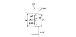
一方、特にこのようにスローアウェイチップのチップ本体の逃げ面とされる他の周面に対応する圧粉体の他の周面に、この他の周面を成形するダイ24のダイ側摺接面24Dにキャビティー23の外側に向けて後退する凹部26を形成することにより、この他の周面においてパンチ21,22が離間する方向側に隣接する部分に対して相対的に凸となる突出部を成形するような場合上述のように上下パンチ21,22によるパンチ離接方向への圧縮力に基づいてこの凹部26に原料粉末が充密して上記突出部が成形されることから、例えば図12および図13に示す第4の参考例のプレス成形金型のように、この凹部26内のパンチ離接方向における最大幅Wを、該凹部26のキャビティー23内側への開口部の最小幅よりも大きくするようにしても、該凹部26内に原料粉末を充密させることができる。 On the other hand, in particular, the die side sliding contact of the die 24 for molding the other peripheral surface to the other peripheral surface of the green compact corresponding to the other peripheral surface as the flank of the tip body of the throw-away tip as described above. By forming a concave portion 26 that recedes toward the outside of the cavity 23 on the surface 24D, a protrusion that is relatively convex with respect to a portion adjacent to the direction in which the punches 21 and 22 are separated on the other peripheral surface. When molding the part , as described above, since the raw material powder is packed into the concave portion 26 based on the compressive force in the punch separating direction by the upper and lower punches 21 and 22, the protruding portion is molded. For example , as in the press-molding die of the fourth reference example shown in FIGS. 12 and 13, the maximum width W in the punch separating / attaching direction in the recess 26 is set to the opening of the recess 26 inside the cavity 23. Larger than the minimum width To be, it can be Takashimitsu raw material powder into the recess 26.

すなわち、この第4の参考例では、凹部26が、上記ダイ側摺接面24Dに対して後退するように形成されるとともに、パンチ離接方向を向くその上記壁面26Bの少なくとも一方が、この凹部26のダイ側摺接面24Dへの開口部に対しキャビティー23の外側に向けてパンチ21,22が互いに離間する方向にも後退するように形成されている。そして、上記パンチ離接方向への圧縮力に基づいてこの凹部26内に押し込まれた原料粉末は、該凹部26内でこのパンチ21,22が離間する方向にも押圧されて充密されることとなるので、この凹部26のキャビティー23内側への開口部における圧粉体の厚さよりも厚い突出部を該圧粉体の周面に成形することが可能となるのである。 That is, in the fourth reference example , the recess 26 is formed so as to recede with respect to the die-side sliding contact surface 24D, and at least one of the wall surface 26B facing the punch separation / contact direction is formed in the recess. The punches 21 and 22 are formed so as to recede toward the outer side of the cavity 23 with respect to the opening portion of the die 26 on the slidable contact surface 24D. The raw material powder pressed into the recess 26 based on the compressive force in the punch separation / contact direction is also pressed and packed in the recess 26 in the direction in which the punches 21 and 22 are separated from each other. Therefore, it is possible to form a protrusion that is thicker than the thickness of the green compact at the opening of the recess 26 inside the cavity 23 on the peripheral surface of the green compact.

ここで、本参考例では上記凹部26は、ダイ側摺接面24Dに対して一段凹むように後退したパンチ離接方向に沿って延びる平坦な底面26Aと、この底面26Aのパンチ離接方向の周縁部からキャビティー23の内側に向けてダイ側摺接面24Dに延びる壁面26Bとから構成されていて、これらの壁面26Bがキャビティー23内側に向かうに従いパンチ21,22が離間する方向に延びた後に該パンチ21,22が接近する方向に延びるように向きを変えて上記ダイ側摺接面24Dに交差するように形成されることにより、この壁面26Bが向きを変えた位置同士のパンチ離接方向の幅である凹部26の最大幅Wが、該壁面26Bとダイ側摺接面24Dとの交差部分のパンチ離接方向の幅である凹部26のキャビティー23内側への開口部の最小幅よりも大きくなるようにされている。従ってこの凹部26のキャビティー23内側への開口部の最小幅は、該凹部26のパンチ離接方向を向く壁面26Bに連なってキャビティー23内側に凸となる突端間のパンチ離接方向の上記間隔Eと等しくなる。 Here, in the present reference example , the concave portion 26 includes a flat bottom surface 26A extending along the punch separation direction retracted so as to be recessed by one step with respect to the die side sliding contact surface 24D, and the bottom surface 26A in the punch separation direction. It is comprised from the wall surface 26B extended from the peripheral part toward the inner side of the cavity 23 at the die side sliding contact surface 24D, and these wall surfaces 26B extend in the direction in which the punches 21 and 22 are separated from each other toward the inner side of the cavity 23. Then, the punches 21 and 22 are formed so as to extend in the approaching direction so as to intersect with the die side sliding contact surface 24D, so that the wall surface 26B is separated from the punches at the positions where the directions are changed. The maximum width W of the recess 26, which is the width in the contact direction, is the opening of the recess 26, which is the width in the punch separation direction at the intersection of the wall surface 26B and the die-side sliding contact surface 24D, to the inside of the cavity 23. It is made larger than the minimum width of the part. Therefore , the minimum width of the opening of the concave portion 26 to the inside of the cavity 23 is such that the width of the concave portion 26 is continuous with the wall surface 26B facing the punch separating direction of the concave portion 26 so It becomes equal to the interval E.

より具体的に、この壁面26Bは、上記底面26Aに滑らかに接して断面が1/4を越える凹円弧等の凹曲面状に形成されており、これにより凹部26の断面は図13に示すようにパンチ離接方向に延びる略長円状とされている。従って、このように壁面26Bの断面が1/4を越える凹円弧状とされている場合には、上記最大幅Wは両壁面26Bの底面26Aから1/4円弧の位置同士の間のパンチ離接方向の間隔となる。なお、この壁面26Bがダイ側摺接面24Dと交差する部分は、上記凹曲面状のままとされていてもよく、またこの凹曲面に滑らかに接してキャビティー23の内側に向かうに従いパンチ21,22が互いに接近する方向に向かう平面状とされていてもよい。   More specifically, the wall surface 26B is formed in a concave curved surface shape such as a concave arc having a cross section of more than ¼ that is in smooth contact with the bottom surface 26A. It is made into the substantially ellipse shape extended in a punch separation / contact direction. Therefore, when the cross-section of the wall surface 26B is a concave arc shape exceeding 1/4, the maximum width W is the punch separation between the positions of the 1/4 arc from the bottom surface 26A of both wall surfaces 26B. The distance is in the tangential direction. The portion where the wall surface 26B intersects with the die side sliding contact surface 24D may be left in the shape of the concave curved surface, and the punch 21 is smoothly in contact with the concave curved surface toward the inside of the cavity 23. , 22 may be formed in a planar shape in a direction approaching each other.

また、本参考例では、上下パンチ21,22のプレス面21A,22Aが、該パンチ21,22が互いに接近する方向に向けて凸となる断面V字等の凸形状とされていて、ダイ24の凹部26側に向けて互いの間隔が漸次大きくなる傾斜面とされており、これらのプレス面21A,22Aが上記ダイ側摺接面24Dに摺接するパンチ側摺接面21B,22Bとなす交差角は鈍角とされ、かつ凹部26の壁面26Bがダイ側摺接面24Dとなす交差角の補角をなすようにされ、上下パンチ21,22を接近させてキャビティー23を画成した状態で、これらのプレス面21A,22Aと壁面26Bとが面一に連なるようにされている。なお、このように構成されたプレス成形金型から圧粉体を抜き出すには、ダイ24を、図12に矢線Cで示すようにパンチ離接方向に分割して離接可能とするか、図3に矢線Aで示したダイ側摺接面24Dに平行な水平方向(図12の図面に直交する方向)に分割して離接可能とすればよい。 Further, in this reference example , the press surfaces 21A and 22A of the upper and lower punches 21 and 22 have a convex shape such as a V-shaped cross section that is convex toward the direction in which the punches 21 and 22 approach each other. The press surfaces 21A and 22A intersect with the punch-side sliding contact surfaces 21B and 22B that are in sliding contact with the die-side sliding contact surface 24D. The angle is obtuse, and the wall surface 26B of the recess 26 forms a complementary angle of the intersection angle formed with the die-side sliding contact surface 24D, and the cavity 23 is defined by bringing the upper and lower punches 21 and 22 closer to each other. The press surfaces 21A and 22A and the wall surface 26B are arranged to be flush with each other. In order to extract the green compact from the press-molding die configured in this way, the die 24 is divided in the punch separation direction as shown by the arrow C in FIG. What is necessary is just to divide | segment and make contact possible in the horizontal direction (direction orthogonal to drawing of FIG. 12) parallel to the die | dye slidable contact surface 24D shown by the arrow A in FIG.

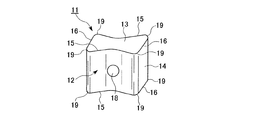
図14は、このように構成されたプレス成形金型によって成形された圧粉体から製造されるスローアウェイチップを示すものであって、そのチップ本体11は、上記平板面12が切刃15の中央部に向かうに従い凹V字型に凹むように形成されて、すくい面13がキャビティー23の断面形状に合わせて蝶型をなしており、また上記平板面12と他の周面14との交差稜線部は凸曲面状とされて、切刃15,16のコーナ部19は1/4を越える円弧等の凸曲線状とされている。なお、平板面12の上記チップ取付穴18周辺は、例えばすくい面13間を結ぶ方向においてチップ本体11の厚さ方向に垂直な平坦面とされていてもよい。このようなスローアウェイチップは、圧粉体において突出部が形成された上記他の周面14とすくい面13との交差稜線の切刃16を使用する場合、この切刃16にコーナ部19を介して交差する切刃15および平板面12に、すくい面13に沿って該切刃16から離間する方向に逃げが与えられるので、例えばこの切刃16によって被削材に溝入れ加工を行う場合のスローアウェイチップとして使用することができる。   FIG. 14 shows a throw-away tip manufactured from a green compact formed by a press-molding die configured as described above. The tip body 11 has a flat plate surface 12 with a cutting edge 15. The rake face 13 is formed in a butterfly shape in accordance with the cross-sectional shape of the cavity 23 and is formed so as to be recessed in a V shape toward the center. The intersecting ridge line portion has a convex curved surface shape, and the corner portion 19 of the cutting blades 15 and 16 has a convex curve shape such as an arc exceeding 1/4. The periphery of the chip attachment hole 18 on the flat plate surface 12 may be a flat surface perpendicular to the thickness direction of the chip body 11 in the direction connecting the rake surfaces 13, for example. In such a throw-away tip, when using the cutting edge 16 of the intersecting ridge line between the other peripheral surface 14 and the rake face 13 in which the protruding portion is formed in the green compact, the corner portion 19 is provided on the cutting edge 16. When the cutting blade 15 and the flat plate surface 12 intersecting with each other are given relief in a direction away from the cutting blade 16 along the rake face 13, for example, when grooving the work material by the cutting blade 16 Can be used as a throwaway tip.

ただし、上記凹部26のパンチ離接方向における最大幅Wがキャビティー23内側への開口部の最小幅(上記間隔E)に対して大きすぎると、上述のようにパンチ21,22によるパンチ離接方向への圧縮力に基づいて上記開口部から凹部26内に押し込まれた原料粉末が、この開口部からキャビティー23外側(底面26A側)に向けて幅広となる凹部26の壁面26B側に十分に充密されず、スローアウェイチップのチップ本体11における上記コーナ部19やこれに連なる平板面12と他の周面14との交差稜線部に変形等が生じるおそれがある。このため、凹部26上記最大幅Wはキャビティー23内側への開口部の最小幅の110%以内とされるのが望ましい。 However, if the maximum width W of the concave portion 26 in the punch separation / attachment direction is too large with respect to the minimum width of the opening to the inside of the cavity 23 (the interval E 2 ), the punch attachment / detachment by the punches 21 and 22 as described above. The raw material powder pushed into the concave portion 26 from the opening portion based on the compressive force in the direction is sufficient on the wall surface 26B side of the concave portion 26 that widens from the opening toward the outside of the cavity 23 (bottom surface 26A side). There is a risk that the corner 19 in the tip body 11 of the throw-away tip or the crossed ridge line portion between the flat plate surface 12 and the other peripheral surface 14 in the throwaway tip may be deformed. For this reason, it is desirable that the maximum width W of the concave portion 26 is within 110% of the minimum width of the opening inside the cavity 23.

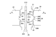
さらにまた、図15は、本発明のプレス成形金型を説明する上での第5の参考例を示す断面図であり、本参考例では上記上下パンチ21,22がさらに、圧粉体においてチップ本体11の上記平板面12中央に対応する部分に、該チップ本体11の厚さ方向に対応する方向に垂直な平坦面を成形する上下内パンチ21D,22Dと、該平板面12のこの平坦面の両外側に対応する部分を、該平坦面部分を除いて上記第4の参考例による圧粉体と同様に断面V字等の谷形に成形する上下外パンチ21E,22Eとから構成されて、これら上下内外パンチ21D,22D,21E,22Eが互いに独立して上記厚さ方向に対応する方向に相対的に離接可能とされている。従って、上下の内パンチ21D,22Dのプレス面21A,22Aはパンチ離接方向に垂直とされ、上下外パンチ21E,22Eのプレス面21A,22Aはキャビティー23の外側すなわちダイ24の凹部26側に向けて互いの間隔が漸次大きくなる傾斜面とされる。 FIG. 15 is a cross-sectional view showing a fifth reference example for explaining the press-molding die of the present invention. In this reference example , the upper and lower punches 21 and 22 are further inserted into chips in the green compact. Upper and lower inner punches 21D and 22D for forming a flat surface perpendicular to a direction corresponding to the thickness direction of the chip main body 11 at a portion corresponding to the center of the flat plate surface 12 of the main body 11, and the flat surface of the flat plate surface 12 The upper and lower outer punches 21E and 22E that are formed into valleys having a V-shaped cross section, like the green compact according to the fourth reference example , except for the flat surface portion, are formed at portions corresponding to both outer sides of the upper and lower outer punches. These upper and lower inner / outer punches 21D, 22D, 21E, and 22E can be separated from each other independently in a direction corresponding to the thickness direction. Accordingly, the press surfaces 21A and 22A of the upper and lower inner punches 21D and 22D are perpendicular to the punch separating direction, and the press surfaces 21A and 22A of the upper and lower outer punches 21E and 22E are outside the cavity 23, that is, on the concave portion 26 side of the die 24. The slopes are gradually inclined toward each other.

従って、このような第5の参考例のプレス成形金型でも、上記第4の参考例と同様に、凹部26内のパンチ離接方向における最大幅Wを該凹部26のキャビティー23内側への開口部の最小幅(上記間隔E)より大きくしても、この凹部26内に原料粉末を確実に充密させて該凹部26のキャビティー23内側への開口部における圧粉体の厚さよりも厚い突出部を圧粉体の周面に成形することができ、このような圧粉体からスローアウェイチップを製造したときに、切刃16にコーナ部19を介して交差する切刃15および平板面12に逃げを与えて、被削材の溝入れ加工等に有効に使用することができる。さらに、本参考例ではパンチ21,22が内外パンチ21D,22D,21E,22Eに分割されて独立して離接可能とされているので、キャビティー23に投入された原料粉末を圧縮する際に、まず内パンチ21D,22Dを接近させて原料粉末をキャビティー23外側に押し出し、次いで外パンチ21E,22Eを接近させることにより、この外側に押し出された原料粉末をさらにキャビティー23外側に押圧して、一層確実かつ効率的に凹部26内に原料粉末を充密させることも可能となる。 Accordingly, even in press-molding die of such fifth reference example, the as with the fourth reference example, of the maximum width W in the punch disjunction direction of the recess 26 into the cavity 23 inside the recess 26 Even if it is larger than the minimum width of the opening (the above-mentioned distance E), the raw material powder is surely packed in the concave portion 26 so as to be larger than the thickness of the green compact in the opening portion inside the cavity 23 of the concave portion 26. A thick protrusion can be formed on the peripheral surface of the green compact, and when a throw-away tip is manufactured from such a green compact, the cutting edge 15 and flat plate intersecting the cutting edge 16 via the corner 19 By providing relief to the surface 12, it can be used effectively for grooving of the work material. Furthermore, in this reference example , the punches 21 and 22 are divided into inner and outer punches 21D, 22D, 21E, and 22E so that they can be separated and connected independently. Therefore, when the raw material powder charged into the cavity 23 is compressed. First, the inner punches 21D and 22D are moved closer to push the raw material powder to the outside of the cavity 23, and then the outer punches 21E and 22E are moved closer to push the raw material powder pushed to the outer side further to the outer side of the cavity 23. Thus, the raw material powder can be more densely and efficiently packed in the recess 26.

ところで、上記第1〜第4の参考例では、図4、図10、図14および図19に示したような方形平板状の縦刃式スローアウェイチップを製造する場合について説明したが、同じ縦刃式スローアウェイチップでも例えば図16および図17に示すような略三角形平板状のチップ本体11を有するスローアウェイチップを製造するのに、特に上記第5の参考例を適用することも可能である。このスローアウェイチップは、やはり被削材の溝入れ加工等に使用されるものであって、そのチップ本体11の厚さ方向を向く三角形状の平板面12のうち、一方の平板面12(図17において上側の平板面12)はその中央部が、また他方の平板面12(図17において下側の平板面12)は略全体が、上記厚さ方向に垂直な平坦面とされるとともに、これらの平板面12がなす三角形の角部分においては、それぞれ該角部で隣接する一対の周面の一方がすくい面13とされるとともに他の周面14が逃げ面とされ、これらすくい面13と他の周面14との交差稜線が切刃16とされている。 By the way, in the first to fourth reference examples , the case of manufacturing the rectangular flat plate type vertical blade type throwaway tip as shown in FIG. 4, FIG. 10, FIG. 14 and FIG. For example , the fifth reference example can also be applied to manufacture a throw-away tip having a substantially triangular flat-plate-shaped tip body 11 as shown in FIGS. . This throw-away tip is also used for grooving of a work material and the like. Of the triangular plate surfaces 12 facing the thickness direction of the chip body 11, one flat plate surface 12 (see FIG. In FIG. 17, the upper flat surface 12) is a flat surface perpendicular to the thickness direction, and the other flat surface 12 (the lower flat surface 12 in FIG. 17) is substantially flat. At the corners of the triangle formed by these flat plate surfaces 12, one of a pair of peripheral surfaces adjacent to each other at the corners is a rake surface 13 and the other peripheral surface 14 is a flank surface. A cutting edge 16 is defined as a crossing ridge line between the outer peripheral surface 14 and the other peripheral surface 14.

そして、この切刃16の両端には凸円弧状をなすコーナ部19が形成されており、これらのコーナ部19に連なる上記他の周面14と平板面12の上記角部分との交差稜線部は、この交差稜線部が延びる方向に直交する断面が該平板面12と他の周面14とに滑らかに連なる凸円弧等の凸曲線をなすように、チップ本体11の厚さ方向外側に向かって周面14に対し相対的に凹となるように後退する凸曲面状に形成されている。さらに、これらの交差稜線部に交差する平板面12の上記角部分のうち、上記一方の平板面12側の部分は、その上記交差稜線部側から該平板面12中央部の上記平坦面側に向かうに従い、反対側の上記他方の平板面12に向けて傾斜する傾斜面とされている。従って、このような三角形平板状のスローアウェイチップを粉末プレス成形による圧粉体から製造しようとすると圧粉体も三角形平板状となるため、例えば特許文献1に記載のように原料粉末を上記チップ本体11の厚さ方向に対応する方向に垂直に圧縮して圧粉体を成形する方法および金型では、原料粉末を均一に圧縮することがますます困難となって現実的には製造することができない。   And the corner part 19 which makes a convex circular arc shape is formed in the both ends of this cutting blade 16, and the intersection ridgeline part of the said other peripheral surface 14 and the said corner | angular part of the flat plate surface 12 which continue to these corner parts 19 The chip body 11 faces outward in the thickness direction so that a cross section perpendicular to the extending direction of the intersecting ridge line forms a convex curve such as a convex arc continuously connecting the flat plate surface 12 and the other peripheral surface 14. Thus, it is formed in a convex curved shape that recedes so as to be relatively concave with respect to the peripheral surface 14. Further, among the corner portions of the flat plate surface 12 intersecting with these intersecting ridge line portions, the portion on the one flat plate surface 12 side is from the intersecting ridge line portion side to the flat surface side of the central portion of the flat plate surface 12. It is set as the inclined surface which inclines toward the said other flat plate surface 12 of an other side as it goes. Therefore, if such a triangular flat plate throwaway tip is manufactured from a green compact by powder press molding, the green compact also becomes a triangular flat plate shape. In the method and mold for forming the green compact by compressing perpendicularly to the direction corresponding to the thickness direction of the main body 11, it is more difficult to uniformly compress the raw material powder, and it is practically manufactured. I can't.

しかして、図18は、このようなスローアウェイチップを製造する場合プレス成形金型の第6の参考例を示す断面図(図16に示したスローアウェイチップのZZ断面に対応する断面図)であり上記第5の参考例と同様に、上下パンチ21,22がそれぞれ上下内パンチ21D,22Dと上下外パンチ21E,22Eとから構成されて、これら上下内外パンチ21D,22D,21E,22Eが互いに独立して相対的に離接可能とされている。ただし、上パンチ21側においては、その上内パンチ21Dのプレス面21Aが、圧粉体において上記一方の平板面12中央部の上記平坦面に対応する部分を成形するようにパンチ離接方向に垂直とされており、これに対して上外パンチ21Eは、三角形平板状に成形される圧粉体の各上記角部分に合わせて3つの上外パンチ21Eが上内パンチ21Dの周囲に配設されて一体にパンチ離接方向に離接可能とされていて、そのプレス面21Aはダイ24の凹部26側に向けて下パンチ22のプレス面22Aとの間隔が漸次大きくなる傾斜面とされている。 Thus, FIG. 18, (cross-sectional view corresponding to ZZ cross-section of the cutting insert shown in FIG. 16) Sixth sectional view showing a reference example of the press molding die in the case of producing such a throw-away tip , and the like the reference example of the fifth, respectively upper and lower inner punches 21D are upper and lower punches 21, 22, 22D and the upper and lower outer punches 21E, is composed of a 22E, the upper and lower inner and outer punches 21D, 22D, 21E, 22E Are relatively separable independently of each other. However, on the upper punch 21 side, the press surface 21A of the upper inner punch 21D is in the punch separation direction so as to form a portion of the green compact corresponding to the flat surface at the center of the one flat plate surface 12. In contrast, the upper and outer punches 21E have three upper and outer punches 21E arranged around the upper and inner punches 21D in accordance with the corner portions of the green compact formed into a triangular flat plate shape. Thus, the press surface 21A is made to be an inclined surface in which the distance from the press surface 22A of the lower punch 22 gradually increases toward the concave portion 26 side of the die 24. Yes.

一方、下パンチ22側においては、上パンチ21の上記上内パンチ21Dと3つの上外パンチ21Eとにそれぞれ対向する位置に下内パンチ22Dと3つの下外パンチ22Eとが配設され、このうち3つの下外パンチ22Eは上外パンチ21Eと同様に一体に該上外パンチ21E側に向けて離接可能とされている。ただし、これら下内外パンチ22D,22Eのプレス面22Aは、チップ本体11の上記他方の平板面12の略全体が平坦面とされるのに合わせていずれもパンチ離接方向に垂直な平坦面とされており、キャビティー23が画成された状態で互いに面一となるようにされている。従って、本参考例では、上外パンチ21Eのプレス面21Aのみが、パンチ離接方向に垂直な平面に対して凹部26側に向かうに従い、対向する下パンチ22の下外パンチ22Eにおけるプレス面22Aから離間するように傾斜した傾斜面とされる。また、ダイ24は、三角形平板状の圧粉体の上記各角部分に対応する位置において3分割されて、パンチ離接方向に垂直な方向に離接可能とされている。 On the other hand, on the lower punch 22 side, the lower inner punch 22D and the three lower outer punches 22E are disposed at positions facing the upper inner punch 21D and the three upper and outer punches 21E of the upper punch 21, respectively. Of these, the three lower and outer punches 22E can be separated from and connected to the upper and outer punches 21E in the same manner as the upper and outer punches 21E. However, the press surfaces 22A of these lower inner and outer punches 22D and 22E are both flat surfaces perpendicular to the punch separation direction in accordance with the flat surface of the other flat plate surface 12 of the chip body 11 being flat. The cavities 23 are flush with each other in a defined state. Therefore, in the present reference example , only the press surface 21A of the upper and outer punches 21E moves toward the concave portion 26 with respect to the plane perpendicular to the punch separating direction, and the press surface 22A of the lower outer punch 22E that faces the lower punch 22 is opposed. It is set as the inclined surface inclined so that it may space apart from. Further, the die 24 is divided into three parts at positions corresponding to the respective corner portions of the triangular flat plate-shaped green compact, and can be detached and attached in a direction perpendicular to the punch separating and attaching direction.

従って、このような第6の参考例のプレス成形金型によれば、上述のような三角形平板状のチップ本体11を有するスローアウェイチップでも、原料粉末を均等に圧縮した圧粉体から容易に製造することが可能となる。そして、その上で、チップ本体11の上記他の周面14と平板面12の角部との交差稜線部が上述のような凸曲面状をなして周面14に対して後退しており、これに伴い該スローアウェイチップに製造される圧粉体においては周面14に対応する部分が、パンチ21,22の離間する方向側に隣接する上記交差稜線部に対応する部分に対して相対的に凸となる突出部となるとしても、ダイ24にキャビティー23の外側に向けて後退する凹部26を形成することにより、該凹部26に原料粉末を充密させることによってかかる突出部をこのダイ24側で確実に生成することが可能となる。 Therefore, according to the press-molding die of the sixth reference example as described above, even the throw-away tip having the triangular flat plate-like tip body 11 as described above can be easily obtained from the green compact obtained by uniformly compressing the raw material powder. It can be manufactured. And on that, the intersection ridgeline part of the above-mentioned other peripheral surface 14 of chip body 11 and the corner of flat plate surface 12 has receded from peripheral surface 14 in the shape of a convex curved surface as described above, Accordingly, in the green compact manufactured on the throw-away tip, the portion corresponding to the peripheral surface 14 is relative to the portion corresponding to the intersecting ridge line portion adjacent to the side in which the punches 21 and 22 are separated from each other. Even if it becomes a projecting portion that becomes convex, a recess 26 that recedes toward the outside of the cavity 23 is formed in the die 24, so that the projecting portion is made dense by filling the recess 26 with the raw material powder. It can be reliably generated on the 24 side.

さらに、本参考例でも、凹部26内のパンチ離接方向における最大幅Wを該凹部26のキャビティー23内側への開口部の最小幅(上記間隔E)より大きくしても、この凹部26内に原料粉末を確実に充密させて上記突出部を該凹部26のキャビティー23内側への開口部における圧粉体の厚さよりも厚く成形することができ、かかる圧粉体から製造されたスローアウェイチップにおいて、切刃16の逃げ面とされる上記他の周面14に上記交差稜線部を介して連なる上記平板面12の角部部分に逃げを与えて、当該スローアウェイチップを被削材の溝入れ加工等に有効に使用することが可能となる。加えて、平板面12と他の周面14との交差稜線部が上述のように凸曲面状であったりしても、上下外パンチ21E,22Eのプレス面21A,22Aとパンチ側摺接面21B,22Bとの交差稜線部の強度を確保することができ、さらには上外パンチ21Eのプレス面21Aは、対向するパンチ離接方向に垂直な平坦面とされた下外パンチ22Eのプレス面22Aに対して凹部26側に向かうに従い漸次離間する傾斜面とされているので、この凹部26内への原料粉末の充密を一層確実かつ効率的に促すことが可能となる。 Further, even in this reference example , even if the maximum width W in the punch 26 in the recess 26 is larger than the minimum width of the opening to the inside of the cavity 23 of the recess 26 (the interval E), the recess 26 It is possible to make the raw material powder densely packed and to form the projecting portion thicker than the thickness of the green compact at the opening inside the cavity 23 of the concave portion 26. In the away insert, a relief is given to the corner portion of the flat plate surface 12 connected to the other peripheral surface 14 which is a flank of the cutting edge 16 via the intersecting ridge line portion, and the throw away insert is removed from the work piece. It is possible to use it effectively for grooving. In addition, even if the intersecting ridge line portion between the flat plate surface 12 and the other peripheral surface 14 is a convex curved surface as described above, the press surfaces 21A, 22A of the upper and lower outer punches 21E, 22E and the punch side sliding contact surface The strength of the intersecting ridge line portion with 21B, 22B can be secured, and the press surface 21A of the upper and outer punches 21E is a press surface of the lower outer punch 22E that is a flat surface perpendicular to the opposing punch separation direction. Since the inclined surface is gradually separated from 22A toward the concave portion 26, it is possible to more reliably and efficiently promote the filling of the raw material powder into the concave portion 26.

なお、これら第1〜第4の参考例およびその変形例、そしてびこれらに基づく本発明の一実施形態では上記縦刃式のスローアウェイチップの製造に適用した場合について説明したがスローアウェイチップ以外の他の切削工具の切刃部材をその原料粉末の圧粉体から製造するときにも適用することができ、またスローアウェイチップでも平板状以外のチップ本体を有するものを製造するときにも適用可能である。さらには、平板状のチップ本体を有するスローアウェイチップでも、その厚さ方向を向く平板面がすくい面とされるとともに、この平板面の周りに配置される周面の少なくとも1つが逃げ面とされ、これらすくい面と逃げ面とされる周面との間に切刃が形成されたスローアウェイチップを製造する場合に適用することも可能ではあるが、このようなスローアウェイチップでは、逃げ面とされる他の周面に上述のような突出部が形成されることは通常あり得ず、また上述したような課題、作用効果を考慮すると特に上記縦刃式のスローアウェイチップを製造するのに適用して、より効果的であるということができる。 Incidentally, these first to fourth reference examples and the modifications thereof, and beauty in an embodiment of the present invention based on these, it has been described as applied to the production of throw-away tip of the vertical blade type, except the indexable insert It can also be applied when manufacturing cutting blade members of other cutting tools from green compacts of the raw material powder, and is also applicable when manufacturing throwaway inserts or chips having a chip body other than a flat plate shape. Is possible. Further, even in a throw-away tip having a flat tip body, a flat surface facing the thickness direction is a rake face, and at least one of peripheral surfaces arranged around the flat face is a flank face. It is also possible to apply this method when manufacturing a throw-away tip having a cutting edge formed between the rake face and the peripheral surface to be the flank face. not obtained there usually the protrusion as described above in addition to the peripheral surface is formed to be, also above problems, considering the action and effect, in particular for producing indexable insert of the vertical blade type It can be said that it is more effective when applied to.

1,11 チップ本体
2,12 平板面
3,13 すくい面
4,6,15,16 切刃
5,14 チップ本体1,11の他の周面
7,19 コーナ部
9,18 取付穴
17 突出部
21,22 パンチ
21A,22A プレス面
21B,22B パンチ側摺接面
23 キャビティー
24 ダイ
24C,24D ダイ側摺接面
25 ピン(突部)
26 凹部
26A 凹部26の底面
26B 凹部26の壁面
26C 凸部
D 凹部26のパンチ離接方向を向く両壁面26Bに連なってキャビティー23側に凸となる突端からの深さ
E 凹部26のパンチ離接方向を向く両壁面26Bに連なってキャビティー23側に凸となる突端間のパンチ離接方向の間隔(凹部26のキャビティー23内側への開口部の最小幅)
W 凹部26のパンチ離接方向における最大幅
1,11 Chip body 2,12 Flat surface 3,13 Rake face 4,6,15,16 Cutting edge 5,14 Other peripheral surface of chip body 1,11 7,19 Corner part 9,18 Mounting hole 17 Projection part 21, 22 Punch 21A, 22A Press surface 21B, 22B Punch side sliding contact surface 23 Cavity 24 Die 24C, 24D Die side sliding contact surface 25 Pin (projection)
26 concave portion 26A bottom surface of concave portion 26B wall surface 26C of concave portion 26 convex portion D depth from a protruding end that protrudes toward cavity 23 side along both wall surfaces 26B facing the direction of punch separation of concave portion 26 E punch separation of concave portion 26 The distance in the punch separation direction between the protrusions that are continuous with both wall surfaces 26B facing the contact direction and protrude toward the cavity 23 (the minimum width of the opening of the recess 26 inside the cavity 23)
W The maximum width of the recess 26 in the punch separation / contact direction

Claims (9)

互いに対向して相対的に離接させられるパンチと、接近したこれらパンチの周囲を取り囲むように配設されて該パンチとの間にキャビティーを画成するダイとを備えたプレス成形金型を用いて、上記キャビティーに投入した原料粉末を上記パンチによって圧縮することにより、切削工具の切刃部材に製造される圧粉体をプレス成形する切削工具の切刃部材の製造方法であって、上記ダイに上記キャビティーの外側に向けて後退する凹部を形成して、この凹部に上記パンチによって圧縮される上記原料粉末を充密させることにより、上記圧粉体において上記ダイにより成形される部分に、上記パンチが離間する方向側に隣接する部分に対して相対的に凸となる突出部を成形することを特徴とする切削工具の切刃部材の製造方法。   A press-molding die comprising punches that are opposed to each other and relatively separated from each other, and a die that is disposed so as to surround the adjacent punches and that defines a cavity between the punches. A method for producing a cutting tool member of a cutting tool, wherein the raw powder charged into the cavity is compressed by the punch, thereby pressing the green compact produced on the cutting tool member of the cutting tool, A portion formed by the die in the green compact is formed by forming a recess in the die that recedes toward the outside of the cavity, and filling the recess with the raw material powder that is compressed by the punch. A method of manufacturing a cutting blade member for a cutting tool, comprising: forming a protruding portion that is relatively convex with respect to a portion adjacent to the side in which the punch is separated. 上記切刃部材は、略平板状を呈するチップ本体を有して、該チップ本体の厚さ方向を向く平板面とこの平板面の周りに配置される周面とを備え、この周面に形成されたすくい面と上記平板面との交差稜線と、このすくい面に隣接する他の周面と該すくい面との交差稜線との少なくとも一方に切刃が形成されたスローアウェイチップであって、上記パンチは上記厚さ方向に対応する方向に離接させられ、上記ダイに形成された上記凹部により、上記圧粉体において上記チップ本体の周面に対応する部分に上記突出部を成形することを特徴とする請求項1に記載の切削工具の切刃部材の製造方法。   The cutting blade member has a chip body having a substantially flat plate shape, and includes a flat plate surface facing the thickness direction of the chip main body and a peripheral surface disposed around the flat plate surface, and formed on the peripheral surface A throwaway tip having a cutting edge formed on at least one of the intersecting ridgeline between the rake face and the flat plate surface, and the other ridge face adjacent to the rake face and the rake face, The punch is separated in a direction corresponding to the thickness direction, and the protrusion is formed in a portion corresponding to the peripheral surface of the chip body in the green compact by the concave portion formed in the die. The manufacturing method of the cutting-blade member of the cutting tool of Claim 1 characterized by these. 請求項1または請求項2に記載の切削工具の切刃部材の製造方法に用いられる圧粉体のプレス成形金型であって、互いに対向して相対的に離接させられるパンチと、接近したこれらパンチの周囲を取り囲むように配設されて該パンチとの間にキャビティーを画成するダイとを備え、このダイには、上記キャビティーの外側に向けて後退する凹部が形成されていることを特徴とする圧粉体のプレス成形金型。   A press molding die of a green compact used in the method for manufacturing a cutting blade member of a cutting tool according to claim 1 or 2, wherein the press mold is close to a punch that is opposed to and separated from each other. A die which is disposed so as to surround the peripheries of the punches and defines a cavity between the punches, and the die has a recess which recedes toward the outside of the cavity. A green compact press mold. 上記凹部は、上記パンチの離接方向を向くこの凹部の両壁面に連なって上記キャビティーの内側に向けて凸となるその突端からの深さが、これらの突端間の上記離接方向の間隔以下とされていることを特徴とする請求項3に記載の圧粉体のプレス成形金型。   The recess is connected to both wall surfaces of the recess facing the punching direction of the punch, and the depth from the protruding end protruding toward the inside of the cavity is the distance between the protruding directions between the protruding ends. The green compact press-molding die according to claim 3, characterized in that: 上記凹部は、その内面が滑らかに連続した曲面によって形成されていることを特徴とする請求項3または請求項4に記載の圧粉体のプレス成形金型。   5. The green compact press-molding die according to claim 3, wherein the concave portion is formed by a curved surface having a smoothly continuous inner surface. 上記凹部は、上記パンチの離接方向における最大幅が、上記キャビティー内側への開口部の最小幅よりも大きくされていることを特徴とする請求項3ないし請求項5のいずれかに記載の圧粉体のプレス成形金型。   6. The concave portion according to any one of claims 3 to 5, wherein the concave portion has a maximum width in a direction of separation of the punch that is larger than a minimum width of an opening portion inside the cavity. Press molding mold for green compact. 上記最大幅が上記最小幅の110%以下とされていることを特徴とする請求項6に記載の圧粉体のプレス成形金型。   The green compact press-molding die according to claim 6, wherein the maximum width is 110% or less of the minimum width. 上記ダイが、上記キャビティーを間にして上記パンチの離接方向または該離接方向に垂直な方向に分割されて離接可能とされていることを特徴とする請求項3ないし請求項7のいずれかに記載の圧粉体のプレス成形金型。   8. The die according to claim 3, wherein the die is divided in a direction in which the punch is detached or perpendicular to the direction of the separation with the cavity interposed therebetween. A green compact press mold according to any one of the above. 上記キャビティー内には、互いに接近した上記パンチ間に該パンチの離接方向に突出する突部が設けられることを特徴とする請求項3ないし請求項8のいずれかに記載の圧粉体のプレス成形金型。   The green compact according to any one of claims 3 to 8, wherein a protrusion is provided between the punches that are close to each other in the cavity so as to protrude in a direction of separating the punch. Press mold.
JP2009251992A 2009-11-02 2009-11-02 Method of manufacturing cutting blade member of cutting tool and press molding die of green compact used in the manufacturing method Expired - Lifetime JP5195717B2 (en)

Priority Applications (1)

Application Number Priority Date Filing Date Title
JP2009251992A JP5195717B2 (en) 2009-11-02 2009-11-02 Method of manufacturing cutting blade member of cutting tool and press molding die of green compact used in the manufacturing method

Applications Claiming Priority (1)

Application Number Priority Date Filing Date Title
JP2009251992A JP5195717B2 (en) 2009-11-02 2009-11-02 Method of manufacturing cutting blade member of cutting tool and press molding die of green compact used in the manufacturing method

Related Parent Applications (1)

Application Number Title Priority Date Filing Date
JP2009230772A Division JP5152140B2 (en) 2009-10-02 2009-10-02 Method of manufacturing cutting blade member of cutting tool and press molding die of green compact used in the manufacturing method

Related Child Applications (1)

Application Number Title Priority Date Filing Date
JP2009274733A Division JP5195729B2 (en) 2009-12-02 2009-12-02 Method of manufacturing cutting blade member of cutting tool and press molding die of green compact used in the manufacturing method

Publications (3)

Publication Number Publication Date
JP2010023116A true JP2010023116A (en) 2010-02-04
JP2010023116A5 JP2010023116A5 (en) 2012-04-05
JP5195717B2 JP5195717B2 (en) 2013-05-15

Family

ID=41729441

Family Applications (1)

Application Number Title Priority Date Filing Date
JP2009251992A Expired - Lifetime JP5195717B2 (en) 2009-11-02 2009-11-02 Method of manufacturing cutting blade member of cutting tool and press molding die of green compact used in the manufacturing method

Country Status (1)

Country Link
JP (1) JP5195717B2 (en)

Citations (3)

* Cited by examiner, † Cited by third party
Publication number Priority date Publication date Assignee Title
JPH01100206A (en) * 1987-10-12 1989-04-18 Komatsu Ltd Method for molding powder
JPH1071497A (en) * 1996-08-29 1998-03-17 Mitsubishi Materials Corp Method and device for production of throw away chip
JP2000144211A (en) * 1998-11-06 2000-05-26 Toshiba Tungaloy Co Ltd Die for powder molding, forming method of green compact, and positive tip

Patent Citations (3)

* Cited by examiner, † Cited by third party
Publication number Priority date Publication date Assignee Title
JPH01100206A (en) * 1987-10-12 1989-04-18 Komatsu Ltd Method for molding powder
JPH1071497A (en) * 1996-08-29 1998-03-17 Mitsubishi Materials Corp Method and device for production of throw away chip
JP2000144211A (en) * 1998-11-06 2000-05-26 Toshiba Tungaloy Co Ltd Die for powder molding, forming method of green compact, and positive tip

Also Published As

Publication number Publication date
JP5195717B2 (en) 2013-05-15

Similar Documents

Publication Publication Date Title
JP5079524B2 (en) Method and apparatus for manufacturing cutting insert
JP6875515B2 (en) Cemented Carbide Pressed Product Manufacturing Method and Equipment and Cemented Carbide Pressed Product
JP5354053B2 (en) Method of manufacturing cutting blade member of cutting tool and press molding die of green compact used in the manufacturing method
US11666966B2 (en) Powder molding press method of green compact for cutting insert, and powder molding press device
JP4920172B2 (en) Method of manufacturing cutting blade member of cutting tool and press molding die of green compact used in the manufacturing method
JP4920171B2 (en) Method for manufacturing throwaway chip and press molding die for green compact used in the manufacturing method
JP5152140B2 (en) Method of manufacturing cutting blade member of cutting tool and press molding die of green compact used in the manufacturing method
JP5195717B2 (en) Method of manufacturing cutting blade member of cutting tool and press molding die of green compact used in the manufacturing method
JP5195729B2 (en) Method of manufacturing cutting blade member of cutting tool and press molding die of green compact used in the manufacturing method
JP5195829B2 (en) Method of manufacturing cutting blade member of cutting tool and press molding die of green compact used in the manufacturing method
JP5158130B2 (en) Method of manufacturing cutting blade member of cutting tool and press molding die of green compact used in the manufacturing method
JP5152123B2 (en) Method of manufacturing cutting blade member of cutting tool and press molding die of green compact used in the manufacturing method
JP4952757B2 (en) Method of manufacturing cutting blade member of cutting tool and press molding die of green compact used in the manufacturing method
JP5158129B2 (en) Method for manufacturing throwaway chip and press molding die for green compact used in the manufacturing method
CN210231192U (en) Punching die structure of side wall hole
JP4529620B2 (en) Method of manufacturing cutting blade member of cutting tool and press molding die of green compact used in the manufacturing method
CN207238868U (en) A kind of punch die structure of punching shaping of elongated needle
JP5045780B2 (en) Method of manufacturing cutting blade member of cutting tool and press molding die of green compact used in the manufacturing method
JP2011098392A (en) Method for manufacturing cutting edge member of cutting tool, and press-forming die for green compact used in the same
JP4869567B2 (en) Method of manufacturing cutting blade member of cutting tool and press molding die of green compact used in the manufacturing method
JP2010023116A5 (en)
JP6380127B2 (en) Press molding method and press mold of green compact for cutting insert
JP5935606B2 (en) Manufacturing method of cutting insert
JP2010046718A5 (en)
CN213829286U (en) Long-life pore punching die

Legal Events

Date Code Title Description
A521 Request for written amendment filed

Free format text: JAPANESE INTERMEDIATE CODE: A523

Effective date: 20091202

A621 Written request for application examination

Free format text: JAPANESE INTERMEDIATE CODE: A621

Effective date: 20091202

A977 Report on retrieval

Free format text: JAPANESE INTERMEDIATE CODE: A971007

Effective date: 20120105

A521 Request for written amendment filed

Free format text: JAPANESE INTERMEDIATE CODE: A523

Effective date: 20120217

A131 Notification of reasons for refusal

Free format text: JAPANESE INTERMEDIATE CODE: A131

Effective date: 20120403

TRDD Decision of grant or rejection written
A01 Written decision to grant a patent or to grant a registration (utility model)

Free format text: JAPANESE INTERMEDIATE CODE: A01

Effective date: 20130108

A61 First payment of annual fees (during grant procedure)

Free format text: JAPANESE INTERMEDIATE CODE: A61

Effective date: 20130121

FPAY Renewal fee payment (event date is renewal date of database)

Free format text: PAYMENT UNTIL: 20160215

Year of fee payment: 3

R150 Certificate of patent or registration of utility model

Ref document number: 5195717

Country of ref document: JP

Free format text: JAPANESE INTERMEDIATE CODE: R150

Free format text: JAPANESE INTERMEDIATE CODE: R150

EXPY Cancellation because of completion of term