JP2010022028A - Video-monitoring system - Google Patents
Video-monitoring system Download PDFInfo
- Publication number
- JP2010022028A JP2010022028A JP2009216857A JP2009216857A JP2010022028A JP 2010022028 A JP2010022028 A JP 2010022028A JP 2009216857 A JP2009216857 A JP 2009216857A JP 2009216857 A JP2009216857 A JP 2009216857A JP 2010022028 A JP2010022028 A JP 2010022028A
- Authority
- JP
- Japan
- Prior art keywords
- video
- data
- recording
- video data
- server
- Prior art date
- Legal status (The legal status is an assumption and is not a legal conclusion. Google has not performed a legal analysis and makes no representation as to the accuracy of the status listed.)
- Granted
Links
Images


Abstract
Description
本発明は、映像の記録再生システムおよび記録再生方法に関し、特に、インターネットやローカルエリアネットワークなどで映像を伝送、記録、閲覧する映像の記録再生システムおよび記録再生方法に関するものである。 The present invention relates to a video recording / reproducing system and a recording / reproducing method, and more particularly to a video recording / reproducing system and a recording / reproducing method for transmitting, recording, and browsing a video over the Internet or a local area network.
映像監視システムあるいは画像配信システムなどの映像システム分野(以下映像システムと称する。)では、インターネットやLAN(Local Area Network)などのIP(Internet Protocol)ネットワークを伝送路として映像データを伝送する映像伝送装置のニーズが急速に拡大している。このような映像システムでは、カメラと映像伝送装置を組合せたもの、あるいはネットワークカメラ(カメラと映像伝送装置が一体に構成されたカメラを言う。)が使用され、そこからの映像データをネットワークから直接記録するレコーダ(以下映像記録サーバと称する。)が主流になりつつある。なお、上述の映像伝送装置は、カメラで撮影された映像をネットワークに伝送するために、例えば、MPEG2(Moving Picture Expert Group Phase 2)やMPEG4で映像を圧縮し、映像のストリームデータ(以下映像データと称する。)に変換する装置である。 In a video system field (hereinafter referred to as a video system) such as a video monitoring system or an image distribution system, a video transmission device that transmits video data using an IP (Internet Protocol) network such as the Internet or a LAN (Local Area Network) as a transmission path. Needs are expanding rapidly. In such a video system, a combination of a camera and a video transmission device or a network camera (referred to as a camera in which the camera and the video transmission device are integrated) is used, and video data from the camera is directly transmitted from the network. Recording recorders (hereinafter referred to as video recording servers) are becoming mainstream. Note that the above-described video transmission apparatus compresses video using, for example, MPEG2 (Moving Picture Expert Group Phase) 2 or MPEG4 and transmits video stream data (hereinafter referred to as video data) in order to transmit video captured by a camera to a network. Device).
而して、従来のカメラでは、テレビ(TV)の標準方式であるNTSC方式などのアナログ形式の映像データを同軸ケーブルを用いて伝送しているが、アナログ信号として伝送するため、伝送途中で減衰やノイズによる劣化が生じ画質が劣化すると言う欠点があった。また、カメラごとに同軸ケーブルを敷設しなければならないため、遠隔であるほどケーブル敷設費が膨大となり、実用化される遠隔監視システムは、非常に限られたものとなっていた。 Thus, in conventional cameras, video data in an analog format such as the NTSC standard, which is a standard system of television (TV), is transmitted using a coaxial cable, but is attenuated during transmission because it is transmitted as an analog signal. In other words, the image quality deteriorates due to deterioration due to noise. Moreover, since it is necessary to lay a coaxial cable for each camera, the cable laying cost becomes enormous as it is remote, and the remote monitoring system that is put into practical use is very limited.
しかしながら上述したネットワークカメラや映像伝送装置からの映像データは、インターネットや構内LANなどのIPネットワークが既に建物内や地域に広く既設されており、新たにIPネットワークを敷設する等の敷設工事が不要となり、極めて容易に映像システムを構築できるようになった。その結果、例えばインターネットに接続すれば、国内は勿論のこと、海外からでも、現地の映像を非常に簡単に見ることが可能となる。また、新規に敷設する場合でも、例えば、無線LANを使用すれば、中継局を設置するだけで、カメラまでの伝送路を設置する等の工事が不要となり、敷設コストを大幅に削減できる。 However, the video data from the network cameras and video transmission devices described above already have IP networks such as the Internet and local area LANs already installed widely in buildings and areas, and installation work such as newly laying IP networks becomes unnecessary. The video system can be constructed very easily. As a result, for example, if it is connected to the Internet, it is possible to view local videos very easily, not only in Japan but also from overseas. In addition, even when newly laying, for example, if a wireless LAN is used, it is not necessary to install a transmission path to the camera by simply installing a relay station, and the laying cost can be greatly reduced.
また、中継伝送用の機器も一般的なパソコン系周辺機器をそのまま利用できるため、アナログカメラに比べて非常に安価である。また、IPネットワークシステムであるため、様々な種類のネットワークコンポーネント(センサ、パソコン、サーバなど)と連携したシステム設計が容易となる。例えば、ICカードを用いた建物内の入退出管理システムでは、入退出者の顔写真映像をネットワークカメラで撮影し、入退出管理データベースと共に、顔写真の写った人物のフレーム画像を一緒に格納することで、入退出情報と映像を連携させた高度なセキュリテイ・ネットワークシステムが構築できる。 In addition, since relay transmission equipment can use general PC peripheral equipment as it is, it is much cheaper than an analog camera. In addition, since it is an IP network system, it is easy to design a system in cooperation with various types of network components (sensors, personal computers, servers, etc.). For example, in an entrance / exit management system in a building using an IC card, a face photo image of an entrance / exit person is taken with a network camera, and a frame image of a person with a face photo is stored together with an entrance / exit management database. This makes it possible to construct an advanced security network system that links entry / exit information and video.
IPネットワークを用いた映像システムは、以上のように多くの利点があるが、基盤となる技術・部品がパソコン系周辺機器であるため、アナログカメラシステムに比べて信頼性が低い。また、基盤となるIPネットワークは、NTSC方式と異なり、データ欠損、例えば、映像データをパケット化して送る場合のパケットの破棄を前提とする非同期型の通信方式である。このため、コンピュータウイルスや突発的なネットワーク負荷の発生によって、映像が一時的に遮断したり、あるいは最悪の場合には、映像システム全体がダウンしたりすることも起こりえる。 A video system using an IP network has many advantages as described above, but is less reliable than an analog camera system because the underlying technology and components are personal computer peripherals. Unlike the NTSC system, the underlying IP network is an asynchronous communication system that assumes data loss, for example, discarding packets when video data is packetized and sent. For this reason, the video may be temporarily interrupted due to the occurrence of a computer virus or sudden network load, or in the worst case, the entire video system may be down.
また、パソコン系周辺機器は、機器レベルでもアナログカメラシステムに比べて不安定である。カメラや記録装置などの映像機器の高機能化および複雑化に伴い、ウインドーズ(Windows:Microsoft社の登録商標)やリナックス(Linux:登録商標)などの高機能かつ複雑なOS(Operating System)が採用されるようになり、映像システムがフリーズすることが散見されるようになった。このため、映像システムでも高度な信頼性を要求される場合には、データセンタのサーバのようにネットワークや機器を二重化あるいはクラスタ化するなどの対策が必要となってきている。 In addition, personal computer peripherals are unstable even at the device level compared to analog camera systems. High-function and complex OS (Operating System) such as Windows (registered trademark of Microsoft) and Linux (registered trademark) are adopted as video devices such as cameras and recording devices become more sophisticated and complicated. As a result, the video system has been seen to freeze. For this reason, when a high degree of reliability is required even in a video system, it is necessary to take measures such as duplication or clustering of networks and devices like a server in a data center.
なお、ここでいう「二重化」とは、通常メインで動作させるサーバと全く同じ機能を果たすサーバをバックアップ用にもう一台用意し、メイン用サーバに障害が発生した際にバックアップ用のサーバに切り替え、障害発生後も継続してシステムが運用されるものである。ただし、バックアップ用サーバは、メイン用サーバを常時ミラーリングする必要がある。ここでミラーリングとは、バックアップ用サーバは、メイン用サーバと同じデータが書きこまれ、動作も同じ動作をしていることを意味する。 Note that “duplexing” here refers to preparing another server for backup that performs exactly the same function as the server that is normally operated on the main server, and switching to the backup server when a failure occurs on the main server The system is continuously operated even after a failure occurs. However, the backup server must always mirror the main server. Here, mirroring means that the backup server is written with the same data as the main server and operates in the same manner.
また、「クラスタ化」とは、1つのサーバに集中する負荷の分散を目的とするサーバ構成方式で、複数台のノードサーバ(node server実際の処理を行うサーバ)と負荷分散装置を用いて、仮想的な一台のサーバを構成することを意味する。即ち、複数のノードサーバがクラスタ(Cluster)を構成する。クラスタ化では、障害発生時に障害発生サーバを切離し、他の複数台のサーバ全体で故障発生サーバの処理も分担し、故障発生後も継続してシステムを運用するものである。クラスタ化を適用するためには、個々のノードサーバが等しい機能を持たねばならず、相互にミラーリングされていることが必要がある。また、Webサーバのようにそれぞれのジョブ(job)が独立(各セッションが独立とも言う。)で、クライアントとサーバの間で状態管理を必要としないサービスに利用が限られている。 In addition, “clustering” is a server configuration method for distributing a load concentrated on one server, using a plurality of node servers (servers that perform actual processing of node servers) and a load distribution device. This means configuring a single virtual server. That is, a plurality of node servers form a cluster. In clustering, when a failure occurs, the failed server is disconnected, and the processing of the failed server is shared by other multiple servers, and the system is continuously operated even after the failure occurs. In order to apply clustering, individual node servers must have the same function and must be mirrored to each other. Moreover, each job (job) is independent (each session is also called independent) like a Web server, and its use is limited to a service that does not require state management between the client and the server.
二重化技術やクラスタ化技術が標準的に利用されているWebサーバでは、基本的にそれぞれのジョブが動作上独立しており、特定のクライアントとサーバとの間で状態管理を行う必要がないため、フェイルオーバ(fail over)が発生した場合にもクライアントは、その影響を受けることなく、スムーズにブラウジング(browsing 閲覧)を継続できる。ここに、フェイルオーバとは、例えば、2台のサーバを同時に動作させ、1台をメインサーバとして動作させ、メインサーバが動作不能に陥ったときに、2番目のサーバが即時バックアップとしてその処理を引継ぐことを言う。 In a Web server where duplication technology or clustering technology is used as standard, each job is basically independent of operation, and it is not necessary to perform state management between a specific client and server. Even when a failover (fail over) occurs, the client can continue browsing (browsing browsing) smoothly without being affected by the failover. Here, failover is, for example, operating two servers at the same time, operating one as the main server, and when the main server becomes inoperable, the second server takes over the processing as an immediate backup. Say that.
また、従来から知られている複数メディア記録装置(例えば、特許文献1参照。)には、複数の記録デバイスとバックアップデバイスについての記載があるが、この技術は、イベント記録などに要求される記録時の高速応答性を損なわずに、バックアップの作成を可能にする技術を示している。 Further, a conventionally known multiple media recording apparatus (see, for example, Patent Document 1) describes a plurality of recording devices and a backup device. This technique is a recording required for event recording or the like. It shows a technology that makes it possible to create backups without compromising high-speed response.
上述したネットワーク映像配信システムでは、クライアントと配信側サーバとの間の通信形態は、配信側でクライアントを管理する方式が標準的である。このような方式では、障害や過負荷など何らかの理由によってサーバを切り替えなければならない場合、再生状態を管理する情報が失われてしまう。その結果、切断前の状況から継続できず、再度初期状態から情報を入手する以外に方法はなく、障害発生時でもその直前の映像を継続的に閲覧することが不可能であった。 In the network video distribution system described above, the communication mode between the client and the distribution side server is typically a method of managing the client on the distribution side. In such a system, when the server has to be switched for some reason such as failure or overload, information for managing the reproduction state is lost. As a result, it was not possible to continue from the situation before the disconnection, and there was no method other than obtaining the information from the initial state again, and it was impossible to continuously browse the video immediately before the occurrence of the failure.
また、二重化技術あるいはクラスタ化技術を用いたシステムでは、複数台のサーバとの間でデータベースに関するリンク情報、例えば、記録している映像の記録位置情報などにミスマッチが発生し、同じ記録容量の映像記録サーバであっても、それまでの利用状態によって同じ映像であっても記録位置が全く別になるのが普通である。このため、事故等で映像記録サーバが切り替わると、データベースとのリンク情報が全く無関係の映像を指し示すことになる。従って、複数台の映像記録サーバとの間でデータベースに関するリンク情報にミスマッチが発生し、故障等により映像記録サーバが切り替わる時、特定のクライアントとサーバとの間でジョブをスムーズに引き継ぐことができないという問題があった。このため、高信頼のシステムを構築するためには、複数の記録サーバ間でデータベースの組をユニット化して二重化あるいはクラスタ化しなければならず、システムが非常に大掛かりになり、価格や運用面は、勿論のこと、システムの拡張性でも大きな問題があった。 In addition, in a system using a duplication technology or a clustering technology, a mismatch occurs in link information regarding a database, for example, recording position information of a recorded video, with a plurality of servers, and a video having the same recording capacity. Even if it is a recording server, even if it is the same image according to the usage state until then, the recording position is usually completely different. For this reason, when the video recording server is switched due to an accident or the like, the link information with the database indicates a completely irrelevant video. Therefore, when there is a mismatch in the link information related to the database among a plurality of video recording servers and the video recording server is switched due to a failure or the like, the job cannot be taken over smoothly between a specific client and the server. There was a problem. For this reason, in order to build a highly reliable system, the database pair must be unitized and duplicated or clustered between multiple recording servers, the system becomes very large, and the price and operational aspects are Of course, there was a big problem with the scalability of the system.
本発明の目的は、複数台の映像記録サーバに対して等価にアクセスできる映像の記録再生システムおよび記録再生方法を提供することを目的とする。 An object of the present invention is to provide a video recording / reproducing system and a recording / reproducing method capable of equivalently accessing a plurality of video recording servers.
本発明の他の目的は、二重化やクラスタ化のために、複数の映像記録サーバに分散的に映像が記録されても、記録されるデータベースに関連するリンク情報が正しく利用できる映像の記録再生システムおよび記録再生方法を提供することを目的とする。 Another object of the present invention is a video recording / reproducing system in which link information related to a recorded database can be used correctly even if video is recorded in a distributed manner on a plurality of video recording servers for duplication or clustering. It is another object of the present invention to provide a recording / reproducing method.
本発明の他の目的は、リンク情報をデータベースに記録する際に、映像記録サーバのシステムリソースを最小にすることのできる映像の記録再生システムおよび記録再生方法を提供することを目的とする。 Another object of the present invention is to provide a video recording / reproducing system and a recording / reproducing method capable of minimizing system resources of a video recording server when link information is recorded in a database.
本発明の更に他の目的は、記録されるデータベースに関連するリンク情報が時間変動の影響を受けないで利用できる映像の記録再生システムおよび記録再生方法を提供することを目的とする。 Still another object of the present invention is to provide a video recording / reproducing system and a recording / reproducing method in which link information related to a database to be recorded can be used without being affected by time fluctuations.
本発明の更に他の目的は、映像データとリンク情報を一体に生成することのできる映像の記録再生システムおよび記録再生方法を提供することを目的とする。 Still another object of the present invention is to provide a video recording / reproducing system and a recording / reproducing method capable of integrally generating video data and link information.
本発明の映像の記録再生システムは、映像データ入力部と、上記映像データ入力部からの映像データに付与するIDを生成するID付与部と、上記映像データをそれぞれ記録する複数の映像記録装置と、上記複数の映像記録装置に記録された上記映像データを出力する出力部からなり、上記複数の映像記録装置の各々は、ID管理テーブルと映像データ記憶エリアを有し、上記ID管理テーブルのIDと上記映像データ記憶エリアの映像データは、上記映像データの記録位置情報で対応付けられるように構成される。 The video recording / playback system of the present invention includes a video data input unit, an ID adding unit that generates an ID to be added to the video data from the video data input unit, and a plurality of video recording devices that respectively record the video data. And an output unit for outputting the video data recorded in the plurality of video recording devices, each of the plurality of video recording devices having an ID management table and a video data storage area, and an ID of the ID management table And the video data in the video data storage area are associated with each other by the recording position information of the video data.
また、本発明の映像の記録再生システムにおいて、更に、負荷分散装置および上記出力部に接続された出力端末装置を有し、上記負荷分散装置は、上記複数の映像記録装置各々の負荷率を把握し、上記出力端末装置からの上記映像データ要求に対して上記複数の映像記録装置の各々の負荷率に応じて上記映像データ要求を所定の上記複数の映像記録装置のいずれか1つに転送するように構成される。 The video recording / reproducing system of the present invention further includes a load distribution device and an output terminal device connected to the output unit, and the load distribution device grasps a load factor of each of the plurality of video recording devices. Then, in response to the video data request from the output terminal device, the video data request is transferred to any one of the predetermined video recording devices according to the load factor of each of the video recording devices. Configured as follows.
更に、本発明の映像の記録再生方法は、複数の映像データを生成し、上記複数の映像データそれぞれに互いに区別可能なIDを付加し、上記IDを付加された上記映像データを複数の映像記録装置に記録する場合、上記複数の映像記録装置の各々は、ID管理テーブルと映像データ記憶エリアを有し、上記ID管理テーブルのIDと上記映像データ記憶エリアの映像データとは、上記映像データの記録位置情報に対応付けられて記憶され、映像の再生要求に対して上記IDに基づいて上記複数の映像記録装置に記録された映像データから所定の映像データを再生するように構成される。 Furthermore, the video recording / playback method of the present invention generates a plurality of video data, adds a distinguishable ID to each of the plurality of video data, and records the video data to which the ID is added into a plurality of video recordings. When recording to a device, each of the plurality of video recording devices has an ID management table and a video data storage area, and the ID of the ID management table and the video data of the video data storage area are A predetermined video data is reproduced from the video data stored in association with the recording position information and recorded in the plurality of video recording devices based on the ID in response to a video reproduction request.
本発明によれば、映像システムにおいて、カメラで撮像された映像データを記録、閲覧および再生するための機能を二重化あるいはクラスタ化することを実現し、高い信頼性をもたらす映像の記録再生システムおよび記録再生方法を提供できる効果がある。即ち、複数台の映像記録サーバに対して等価にアクセスできる映像の記録再生システムおよび記録再生方法を実現できる。また、本発明によれば、CPU、メモリ、バス帯域などのシステムリソースを最小にしつつ、カメラからのライブ映像と映像記録サーバの記録映像とをシームレスに切り替えることのできる映像の記録再生システムおよび記録再生方法を提供することができる。 According to the present invention, in a video system, a video recording / playback system and a recording system that achieves high reliability by realizing dual or clustering of functions for recording, browsing, and playing back video data captured by a camera. There is an effect that a reproduction method can be provided. That is, it is possible to realize a video recording / reproducing system and a recording / reproducing method capable of equivalently accessing a plurality of video recording servers. In addition, according to the present invention, a video recording / reproducing system and recording capable of seamlessly switching between a live video from a camera and a recorded video of a video recording server while minimizing system resources such as CPU, memory, and bus bandwidth. A reproduction method can be provided.
また、記録された映像データに付加されるIDとセンサ情報に付加されるIDとを共通化することにより映像データとセンサ情報との連携処理を容易にし、システムリソースを最小限度に抑えることが可能である。 Also, by sharing the ID added to the recorded video data and the ID added to the sensor information, the linkage processing between the video data and the sensor information can be facilitated, and system resources can be minimized. It is.
また、二重化やクラスタ化のために、複数の映像記録サーバに分散的に映像が記録されても、記録されるデータベースに関連するリンク情報が正しく利用できる映像の記録再生システムおよび記録再生方法を提供することができる。 Also, for duplication and clustering, a video recording / playback system and recording / playback method are provided that can correctly use link information related to the recorded database even if video is recorded in a distributed manner on a plurality of video recording servers. can do.
また、本発明の映像システムにおいて、映像記録サーバの増設、あるいは認識、検出等の各種センサ情報の増設等、新たな機能の拡張が容易にできる記録再生システムおよび記録再生方法を実現する効果がある。 In addition, the video system of the present invention has the effect of realizing a recording / playback system and a recording / playback method that can easily expand new functions, such as adding a video recording server or adding various sensor information such as recognition and detection. .
更に、記録されるデータベースに関連するリンク情報が時間変動の影響を受けないで利用できる映像の記録再生システムおよび記録再生方法を提供することができる。また、付与されるリンク情報(ID)に順序性と連続性を持たせることにより、記録された映像の所望の部分が記録されているか否かを記録済みのデータ全体を調べることなく、高速に判別できる記録再生システムおよび記録再生方法を提供することができる。 Furthermore, it is possible to provide a video recording / reproducing system and a recording / reproducing method in which link information related to a database to be recorded can be used without being affected by time variation. In addition, by providing the given link information (ID) with order and continuity, it is possible to determine whether or not a desired portion of the recorded video is recorded at high speed without checking the entire recorded data. It is possible to provide a recording / reproducing system and a recording / reproducing method that can be distinguished.
また、映像データとリンク情報(ID)を一体に生成する構成とすることで、信頼性の高い、価格の安い映像の記録再生装置および記録再生方法を提供することができる。 Further, by adopting a configuration in which the video data and the link information (ID) are generated integrally, it is possible to provide a video recording / reproducing apparatus and recording / reproducing method with high reliability and low price.
図1は、本発明の一実施例を説明するための映像システム図である。図1において100は、有線LAN、無線LANあるいはインターネットなどTCP(transmission Control Protocol)/IPプロトコルによる通信を行うIPネットワーク(以下単にネットワークと略称する。また、ネットワークは、伝送路であってもよい。)、200は、映像伝送装置、300は、被写体を撮影する撮像装置、例えばテレビカメラである。400は、センサであって、例えば、侵入者監視用システムでは、侵入者の有無を検出する赤外線センサであったり、あるいはダムの水位を検出する水位センサである。なお、映像伝送装置200は、カメラ300とセンサ400の出力をIPデータに変換してネットワーク100に出力する装置である。即ち、カメラ300の映像出力を例えば、JPEG、MPEG2やMPEG4などの形式に圧縮、符号化しIPデータに変換するとともに、センサ400からのセンサ情報をIPデータ化した映像データ上に重畳し、ネットワーク100に出力する。
FIG. 1 is a video system diagram for explaining an embodiment of the present invention. In FIG. 1,
500は、ネットワークカメラである。ネットワークカメラ500は、カメラ300と映像伝送装置200が一体に構成されたもので、ネットワークカメラ500からの映像データは、直接IPデータとしてネットワーク100に出力される。600は、映像記録サーバであり、映像伝送装置200またはネットワークカメラ500から伝送される映像データを記録する装置である。700は、映像データに、例えば、センサ情報が重畳されている場合には、センサ情報とそのセンサ情報に関連する映像を指定するリンク情報(ID)を登録するためのデータ記録装置(データベース部)である。また、監視システム等では、カメラ300あるいはネットワークカメラ500に内蔵(外付けの場合もある。)されているタイマにより撮影された日時が付されているのが一般的であり、これらの時刻をIDと共にデータ記録装置700に蓄積するものである。
800は、クライアント端末であり、パソコン(PC)あるいは専用のハードウエア構成で実現される。クライアント端末800は、映像伝送装置200またはネットワークカメラ500から伝送されたライブ映像を再生したり、あるいは映像記録サーバ600に記録されている映像を再生したり、データ記録装置700に記録されているデータを再生するために使用される。勿論、クライアント端末800は、必要に応じてカメラ300やネットワークカメラ500のパン、チルト、ズーム等の動作(雲台のような旋回機構等は図示せず。)やセンサ400の動作を従来周知の方法で制御するための機能を有している。
A
なお、図1においては、代表的なものとして各1台を示してあるが、映像伝送装置200、カメラ300、センサ400あるいはネットワークカメラ500は、一般的に、数台から数十台がネットワーク100に接続されて、映像システムを構成するのが普通である。また、クライアント端末800も複数の場所に設置されるのが普通である。
In FIG. 1, one representative is shown as a representative one, but generally, the
図2は、本発明の一実施例の具体的構成を説明するためのブロック図である。図1において、映像記録サーバ600は、例えば、クラスタ化された複数台の映像記録装置600−1、600−2、・・・・600−nで構成されている。610は、ID(Identification)(リンク情報とも言う。)管理テーブル、620は、映像データ記録エリアを示している。なお、ID管理テーブル610および映像データ記録エリア620は、模式的に示したもので、映像記録装置600−1の中では、ハードディスク(HD)、光デスクあるいはDVD(Digital Versatile Disc)等の記録媒体上に記録された記録エリアを意味している。また、ID管理テーブル610は、高速の検索が要求される場合には、半導体メモリなどに記憶される場合もある。630は、負荷分散装置であり、詳細については後述する。700−1は、データ記録装置であるが、必ずしも必要ではなく、後述するような時間情報あるいはセンサ情報を蓄積する必要がある場合に設けられる。なお、データ記録装置700−1は、映像記録装置600−nの内の一を兼用して使用することもでき、特に、物理的に区別する必要は全くない。クライアント端末800は、入力部810、復号化部820および表示手段830から構成されている。900は、ID付与部であり、詳細については後述する。なお、図1と同じものには同じ符号が付されている。また、図2においては、ネットワーク100は、省略されているが、映像伝送装置200と映像記録サーバ600との間の伝送路およびクライアント端末800と映像記録サーバ600との間の伝送路がネットワーク100に相当する。なお、IDの詳細については後述する。
FIG. 2 is a block diagram for explaining a specific configuration of an embodiment of the present invention. 1, the
次に、図2に示すシステムの動作について説明する。まず、映像データの記録について説明する。映像伝送装置200から出力された映像データは、ID付与部900に入力される。このID付与部900の設置場所は、種々の変形が可能であるが、ここでは、便宜上、映像伝送装置200と伝送路100との間に位置する場合で説明する。ID付与部900は、映像伝送装置200から入力される映像データに対して、映像を参照する単位(あるいは再生する単位)、例えば、TVの1フレーム毎にID(またはID情報)を挿入し、ネットワーク100に出力する。
Next, the operation of the system shown in FIG. 2 will be described. First, video data recording will be described. Video data output from the
IDが付与された映像データは、複数台の記録装置600−1、600−2、・・・・600−nの全てに伝送され、記録される。例えば、ノードサーバである映像記録装置600−1では、映像データがサーバ内部の例えば、ハードディスク上にある映像データ記録エリア620に記録され、確定したエリア上での記録位置情報と、付与されたIDとが対応付けられて、ID管理テーブル610に記録される。
The video data to which the ID is assigned is transmitted to and recorded on all of the plurality of recording devices 600-1, 600-2,... 600-n. For example, in the video recording apparatus 600-1, which is a node server, video data is recorded in the video
ID管理テーブル610と映像データ記録エリア620との関係を図7を用いて更に詳細に説明する。図7(a)は、ID管理テーブル610を、また、図7(b)は、映像データ記録エリア620の記録内容を示している。映像データが映像記録装置600−1に入力されると、図7(b)に示すように映像データ記録エリア620上のエリア621−1に先頭アドレス(位置情報)A1と共に格納される。この映像データに付与されたIDとエリア621−1の位置情報A1は、図7(a)で示すようにID管理テーブル610上のレコード611−1(なお、レコードを総称する場合は、レコード611で示す。)に格納される。即ち、ID(例えば、#101で表示)と位置情報A1とがレコード611−1に格納される。
The relationship between the ID management table 610 and the video
次に、新たな映像データが入力されると、映像データ記録エリア620上のエリア621−2に先頭アドレス(位置情報)A2と共に格納される。この映像データに付与されたIDとエリア621−2の位置情報A2は、ID管理テーブル610上のレコード611−2にID(#102で表示)と位置情報A2とが格納される。以降、新たな映像データが入力される度に、映像データ記録エリア620に順次記録されると共に、映像データ記録エリア620の位置情報Am(m:1、2、・・・)とID(#M)(M=101、102、・・・)がレコード611に順次格納される。
Next, when new video data is input, it is stored in the area 621-2 on the video
なお、映像データが送られる度に上記処理が繰り返されるが、映像データ記録エリア620に空きがなくなると古いデータから順に最新データによって上書きされる。即ち、記録内容が更新される。また、ID管理テーブル610は、これに従って新しいデータが追加される。また、映像データ記録エリア620の上書きによって参照先が更新されたレコードがあればこれを消去する。以上、映像記録装置600−1について詳細に説明したが、ID付与部900からの映像データと各映像データ毎に付与されるID情報とが映像記録装置600−2、・・・600−nにも映像記録装置600−1と同様に入力され、それぞれの映像記録装置が持っているID管理テーブルおよび映像データ記録エリアに同様の方法で記録される。従って詳細な説明は省略する。
The above process is repeated each time video data is sent, but when the video
また、映像データに例えば、その映像の撮影日時が時間情報として添付されている場合には、IDと共に時間情報がデータ記録装置700−1に図7と同様に記録される。即ち、時間情報は、映像データ記録エリアに相当する場所に記録される。従って、ID、時間情報および時間情報の記録位置情報は、図7に示すものと同様である。なお、映像記録装置600−1、600−2、・・・600−nの記録容量は、それぞれ撮像画像を3日〜1ヶ月間程度蓄積するだけの大容量記憶装置である。 For example, when the shooting date and time of the video is attached as time information to the video data, the time information is recorded together with the ID in the data recording device 700-1 as in FIG. That is, the time information is recorded at a location corresponding to the video data recording area. Accordingly, the ID, time information, and recording position information of the time information are the same as those shown in FIG. The recording capacities of the video recording devices 600-1, 600-2,... 600-n are large-capacity storage devices that only store captured images for about three days to one month.
次に映像データの再生について説明する。ユーザから再生要求がクライアント端末800に与えられると、入力部810では、再生要求が画像要求命令を基に生成され、クラスタ化されたネットワーク映像記録サーバ600に伝送される。このとき、記録されている映像の記録場所を指定するIDが画像要求命令に添付される。なお、クライアント端末800の画像要求入力(検索入力)と表示画面について、図8を用いて説明する。
Next, reproduction of video data will be described. When a reproduction request is given from the user to the
クライアント端末800は、キーボードのような入力部810、映像データを復号する復号化器820および表示手段830からなり、その検索および結果の表示画面の一実施例を図8に示す。図8において850は、例えば、検索および結果の表示画面であり、検索および結果の表示画面850は、検索条件指定画面851、検索結果一覧表示画面852および再生画面853で構成されている。
The
クライアント端末800から再生要求として検索条件指定画面851に例えば、キーボード等の入力機器810で、検索項目としてセンサ1を指定する。この場合、センサ1は、撮影するカメラのNo.1のカメラに相当する。また、検索開始時刻:2002年1月1日0時0分〜検索終了時刻2002年3月31日23時29分を入力し、時間表示順は、降順、検索結果の表示数は、25枚を入力し、検索ボタンをクリックする。
For example, the sensor 1 is designated as a search item on the search
この検索条件がクライアント端末800から入力されると、まず、検索条件にある検索開始時間と検索終了時間に相当する該当IDをデータ記録装置700−1から読み出し、そのIDに該当する画像データの縮小画像(サムネール画像)を負荷分散装置630を介して映像記録サーバ600から読み出し、検索結果一覧表示画面852に縮小画像854−1、854−2、・・・854−25(25枚の検索結果を表示している。)として表示される。ここで映像データの縮小画像(サムネール画像)854とは、1フレームの画像の画素数を間引いた画素であり、検索結果一覧表示画面852内に多数の画像を表示するための画像である。また、縮小画像854は、一連の撮影画像の全ての縮小画像を表示するのではなく、例えば、従来から良く知られている映像の変化のあるフレームの縮小画像が代表画像として選択され、表示される。なお、ユーザの必要に応じて検索結果一覧表示画面852には、撮像日時も表示される。
When this search condition is input from the
次に、負荷分散装置630の動作について説明する。付与されたIDにより画像データを各映像記録装置600−1、600−2、・・・600−nから読み出す場合、負荷分散装置630は、クラスタ内のノードサーバである映像記録サーバ600の負荷状態を見て、もっとも負荷が低いサーバに、クライアント800からの再生要求を転送する。負荷分散装置630は、ネットワーク100に接続されている複数のクライアント端末800からの再生要求に対して各映像記録装置600−1、600−2、・・・600−nの負荷に応じて接続先を切替え、再生要求を転送する働きをする。例えば、負荷分散装置630は、内部に表1に示すような各映像記録装置の管理テーブルを備えている。
Next, the operation of the load balancer 630 will be described. When the image data is read from each of the video recording devices 600-1, 600-2,... 600-n using the assigned ID, the load distribution device 630 loads the
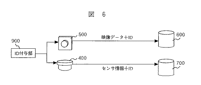
表1は、所定時点での各映像記録装置毎の負荷率を示している。ここで負荷率とは、例えば、各映像記録装置にクライアント端末からアクセスされる再生要求命令数を%表示したものである。従って、クライアント端末800から再生要求があると、負荷分散装置630は、このテーブルを参照し、負荷率の低い映像記録装置に再生要求を転送する。例えば、映像記録装置600−1の負荷率が40%と最も低いので、再生要求を映像記録装置600−1に転送する。なお、良く使用されるラウンド・ロビン(round robin)方式、所謂、再生要求が発生する度に各映像記録装置600−1、600−2、・・・600−nに順次再生要求を転送する方式では、全ての映像記録装置の負荷率は、ほぼ均一にすることができる。但し、負荷分散装置630の動作をテーブル方式とするか、ラウンド・ロビン(round robin)方式とするかは、映像システムの設計あるいは再生要求の使用状況によって決められることは言うまでもない。
Table 1 shows the load factor for each video recording apparatus at a predetermined time point. Here, the load factor is, for example, the percentage of the number of playback request commands accessed from the client terminal to each video recording device. Therefore, when there is a reproduction request from the
再生要求の転送を受けた映像記録装置、例えば、映像記録装置600−1では、再生要求に付与されたIDを基にID管理テーブル610を検索する。該当するレコードがあればそこに書き込まれている映像データ記録エリア620での位置情報Amを基に、ハードディスクから映像データを読み出してクライアント800に伝送する。受け取った映像データは復号化器820で復号され、適宜縮小画像処理を行い、表示手段830上の検索結果一覧表示画面852に縮小画像854として表示される。
The video recording apparatus that has received the transfer of the reproduction request, for example, the video recording apparatus 600-1, searches the ID management table 610 based on the ID assigned to the reproduction request. If there is a corresponding record, the video data is read from the hard disk and transmitted to the
次に、表示手段830上の再生画面853について説明する。再生画面853は、映像記録サーバ600に記録されている映像(カメラで撮影され、記録されている映像)を再生する画面を示している。例えば、ユーザが検索結果一覧表示画面852の縮小画像854−12をマウス等でクリックすると、縮小画像854−12に添付されているIDと共に映像の再生要求が負荷分散装置630に入力され、前述した縮小画像854の表示と同様に、映像記録装置600−1、6002、・・・600−3の負荷状況に応じて適宜再生要求が転送され、必要な映像データが再生される。再生画面853では、2002年3月12日16時30分00秒08の画像が再生されている場合を示している。この映像は、静止画あるいは動画を再生することが可能であり、また、その再生速度も自由に変更が可能である。また、再生操作が継続的に行われると、上記の処理が繰り返されるが、負荷分散装置630によって再生要求が転送される映像記録装置は、その時々の各映像記録装置の負荷状況(表1に示す。)によって適宜切り替るが、前述したようにIDを共通化しているため、即座に、対応する映像データを出力できる。従って、クラスタ全体、即ち、映像記録サーバ600としての負荷分散処理が実現される。
Next, the reproduction screen 853 on the
次に、上述した映像データに付与されるIDについて説明する。全てのIDが重複がないことが保障されるのであればどのようなIDでもよいが、伝送容量および記録装置の容量から考えて、なるべくデータ量が少ないほうが望ましい。一方、再生処理の観点からすると、付与されるIDは、順序性があり、連続的であれば欠落の無いことが容易に判定できるので、IDとしては望ましい。例えば、クライアント800が所定のIDで映像データを要求したとする。IDの重複が無いことが保障されていても、付与されるIDが全くのランダムであったとすると、再生要求を受け取った、例えば、映像記録装置600−1では、ID管理テーブル610の全てのIDを調べないと、要求されたIDに対応する画像データが、映像記録装置600−1内にあるかどうかを判別できない。前述したように映像記録装置600−1のハードディスク容量は、極めて大きいなどの理由で、ID管理テーブル610が例えば、半導体メモリ上に収容しきれず、IDの一部がハードディスク上に配置されている場合、ID管理テーブルのサーチ時間が半導体メモリだけの場合の100倍近くかかることになり、要求するIDの映像データが無かった場合の応答レスポンスが大幅に低下してしまう。付与されるIDに順序性があり、連続性があれば、ID管理テーブル610の先頭と末尾のIDを調べて、要求されたIDがその範囲にあるかどうかをチェックするだけで簡単に画像データの有無を判断できるので、順序性と連続性のあるIDを付与することが画像データの検索には都合が良い。
Next, an ID assigned to the above-described video data will be described. Any ID can be used as long as all IDs are guaranteed to be non-overlapping, but it is desirable that the data amount be as small as possible in view of the transmission capacity and the capacity of the recording device. On the other hand, from the viewpoint of reproduction processing, the IDs to be given are desirable as IDs because they are ordered and can be easily determined to be missing if they are continuous. For example, assume that the
上述した条件を満たすIDの一実施例として、自然数を採用した方式について説明する。まず、ID付与部900は、ID付与のための例えば、カウンタ(またはID生成部)を内蔵している。このカウンタを製品出荷時に1に初期化しておく。システムが設置稼動し、ID付与部900に対して、ID付与が要求されるたびに、内部カウンタを1ずつインクリメントし、対応するIDを出力部(図示せず。)から出力する。ただし、この場合、途中でカウンタの初期化を全く許さないようにする必要がある。IDは、有限ビット数であるので、カウンタが再びゼロに戻るとIDとして重複が発生する可能性があるが、例えば、TVの場合、全てのフレーム画像にIDを付与し、毎秒30フレームでIDをインクリメントし続けたとしても、40ビット程度の自然数であれば、約1159年分のフレーム画像に相当するので、ID付与における実用上の問題は起こらない。
As an example of an ID that satisfies the above-described conditions, a method that employs a natural number will be described. First, the
また、ネットワーク機器として良く知られている固有IDであるMACアドレス(48ビット)と組み合わせれば、フレーム画像レベルで世界に唯一のIDを割り当てることが可能になる。この場合、88ビット程度が必要となるが、MACアドレスの内、ネットワークカードを出荷する企業ごとに開放しているビット長が24ビット(=16,777,216)であることから、これを使用すればもっと短いビット長でID付与をすることが可能である。 Further, when combined with a MAC address (48 bits), which is a unique ID well known as a network device, it becomes possible to assign a unique ID to the world at the frame image level. In this case, about 88 bits are required, but the MAC address has a bit length of 24 bits (= 16,777,216) opened for each company that ships the network card. If so, it is possible to assign an ID with a shorter bit length.
従って、システムの適用範囲を限定的にすれば、ネットワーク映像伝送装置200やネットワークカメラ500に割り振る製品番号として24ビットを割り当て、そしてID付与部900の中のカウンタに40ビットを割り当てることにすれば、64ビット程度で実用上十分なIDとして利用が可能となる。また、このようなカウンタ出力のIDに更に、カメラ番号あるいはセンサの番号を組合せたIDとすることも容易に実施できることは言うまでもない。
Therefore, if the application range of the system is limited, 24 bits are assigned as a product number to be assigned to the network
而して、監視システム等では、カメラの撮像時刻を画像データのIDとしてよく使用されている。この時刻をIDとしたタイムコードは、IDとしての条件をほぼ満たすものと考えられがちであるが、例えば、複数のカメラからの画像データがネットワーク100に供給される場合、複数のカメラ間での時刻ずれの問題が発生し、これを解決しない限りタイムコードをIDとして利用できない。即ち、一般的なIT(Information Technology)機器に使用されている時計は、水晶発振器の振動を利用して時間をカウントしているが、個々の水晶発振器は、誤差を持っているため、少しずつ時間のずれが発生する。ネットワーク100では、こうした問題に対応するため、NTP(ネットワーク・タイム・プロトコル)などを使ってネットワーク100上の機器の時刻を調整することが行われているが、この操作によって時刻のずれたIT機器は、時刻を進められたりあるいは戻されたりすることになる。
Thus, in a monitoring system or the like, the imaging time of the camera is often used as an ID of image data. A time code with this time as an ID tends to be considered to substantially satisfy the condition as an ID. For example, when image data from a plurality of cameras is supplied to the
また対象とする映像システムは、映像を取り扱うため、許容される時刻ずれの最小単位は、映像の1フィールド(1フレームの半分)に対応する16msである。一般的なパソコンでは3〜6日の頻度でこの程度のずれが発生するため、時刻ずれを無視することは難しい。また、一般にネットワーク100自身が遅延を許容するメディアであるため、NTPによる時刻修正が完全であることを保障しているものではない。その結果、画像データにタイムコードをIDとして付与した場合、IDの重複や欠落を発生することになる。
In addition, since the target video system handles video, the minimum unit of time shift allowed is 16 ms corresponding to one field of video (half of one frame). In general personal computers, this level of deviation occurs every 3 to 6 days, so it is difficult to ignore the time deviation. In general, since the
なお、現在実用化されている極めて正確な時計として電波時計がある。これは1時間単位で時刻を修正するものであるので、この電波時計をID付与部に設置し、タイムコードをIDとして使用すれば、上述した時間の問題をかなり改善できる。しかし、1時間単位での修正はあるものの、やはりその間での誤差は、発生するので、より正確な電波時計の出現が望まれる。このような正確な電波時計が実現されれば、タイムコードをIDとして使用することができる。また、現在、電波時計周辺の部品単価は、まだまだ高価で、現実のシステムには採用が難しいが、将来、これらの単価が非常に安価になるならば、電波時計によるタイムコードをIDとして十分利用できる。 Note that there is a radio timepiece as a very accurate timepiece that is currently in practical use. Since this corrects the time in units of one hour, the time problem described above can be considerably improved by installing this radio clock in the ID assigning unit and using the time code as the ID. However, although there are corrections in units of one hour, errors still occur in the meantime, so the appearance of a more accurate radio timepiece is desired. If such an accurate radio timepiece is realized, a time code can be used as an ID. Currently, the unit price around the radio clock is still expensive and difficult to adopt in an actual system. However, if these unit prices become very cheap in the future, the time code from the radio clock will be used as the ID. it can.
図3は、本発明の他の一実施例を説明するためのブロック図で、水位情報を取得するセンサと合わせて映像データを記録するダム等の水位監視システムを示している。図3において映像伝送装置200は、符号化器210、ネットワーク伝送器220およびID付与部900から構成されている。700−2は、センサ400からの例えば、水位情報を記録するデータ記録装置であり、710は、映像データに対応して付与されたIDと映像データに対応する水位情報720とを対応付けたデータテーブルを示している。クライアント端末800は、表示手段830、復号化器820、検索手段840および検索結果処理手段850から構成されている。なお、図1および図2と同じものには、同じ符号が付されている。なお、本実施例では、ID付与部900は、映像伝送装置200に内蔵されている場合を示している。また、映像記録装置600−1とデータ記録装置700−2に対して、マルチキャスト(指定先に対する一斉同報伝送方式)を行い、ネットワークの伝送帯域の節約を行っている。
FIG. 3 is a block diagram for explaining another embodiment of the present invention, and shows a water level monitoring system such as a dam for recording video data together with a sensor for acquiring water level information. In FIG. 3, the
次に、図3に示す水位監視システムの動作について説明する。まず、カメラ300とセンサ400からの各出力は、映像伝送装置200に入力される。カメラ300からのアナログ映像出力は、符合化器210でA/D変換された後、ネットワーク伝送器220でJPEGやMPEGなどの圧縮符号化され、更に、水位センサ400からのセンサ情報(水位情報)と共にIPデータ化される。このときID付与部900によって映像参照単位(例えば、1フレーム単位)ごとに前述したIDが付与され、ネットワーク100に出力される。
Next, the operation of the water level monitoring system shown in FIG. 3 will be described. First, each output from the
IDが付与された映像データとセンサ情報(水位情報)は、映像記録装置600−1とデータ記録装置700−2に伝送される。映像記録装置600−1では、図2で説明したと同様に映像データが映像記録装置600−1内部の例えば、ハードディスク上にある映像データ記録エリア620に記録され、確定したエリア上での記録位置情報と付与されたIDとが対応付けられて、ID管理テーブル610に記録される。
The video data and sensor information (water level information) to which the ID is assigned are transmitted to the video recording device 600-1 and the data recording device 700-2. In the video recording apparatus 600-1, video data is recorded in the video
これら映像データ記録エリア620およびID管理テーブル610との関係は、図7に示した関係と同様である。即ち、映像データが入力されると、映像データ記録エリア620上のエリア621−1に格納される。この映像データに付与されたID(この場合#101である。)とエリア621−1上の位置情報A1をID管理テーブル上のレコード611−1に格納する。次に、新たな映像データが入力されると、エリア621−2の位置情報A2とこの映像データに付与されたID(#102)がレコード611−2に格納される。以降、新たな映像データが入力されるたびに、エリア620の位置情報Am(m=1、2、・・・)とID(#M)(M=101、102、・・・)がレコード611−mに順次格納される。映像データが送られるたびに上記処理が繰り返されるが、映像データ記録エリア620に空きがなくなると古いデータから順に最新データによって上書きされる。ID管理テーブル610はこれに従って新しいデータを追加する。また、映像データ記録エリア620の上書きによって参照先が更新されたレコードがあればこれを消去する。一方、映像データは、データ記録装置700−2にも伝送されるが、データ記録装置700−2では、利用されずに廃棄される。
The relationship between the video
データ記録装置700−2では、センサ情報(水位情報)が入力されるとセンサ情報を管理するテーブル710に新規レコードとして追加される。この時、一緒に添付されたIDも同じレコード内に一緒に格納される。例えば、映像データ記録エリア620上のエリア621−1に格納される映像データが、映像伝送装置200から伝送されるときに、センサ情報を管理するテーブル710の最初のレコード711−1にセンサ情報(この場合「水位505cm」と表示してある。)とID情報(この場合「101」と表示)が格納される。次に新たなセンサ情報が受信されると、レコード711−2にセンサ情報(この場合「水位254cm」)とID情報(この場合102)が格納される。以降、新たなセンサ情報を受信するたびに、レコード711にセンサ情報(この場合「水位の高さ」情報)とID情報が順次格納される。データが送られるたびに上記処理が繰り返されるが、センサ情報を管理するテーブル710に空きがなくなると古いデータから順に廃棄され、最新データによって上書きされ、更新される。なお、データ記録装置700−2は、マルチキャストで映像伝送装置200から映像データも送られるが記録されず廃棄される。なお、本実施例では、データ記録装置700−2として説明したが、例えば、図2で示す映像記録装置600−2で兼用することも可能であり、特に、データ記録装置と映像記録装置を区別する必要は全くない。
In the data recording device 700-2, when sensor information (water level information) is input, it is added as a new record to the table 710 that manages the sensor information. At this time, the ID attached together is also stored together in the same record. For example, when the video data stored in the area 621-1 on the video
次に、映像記録装置600−1およびデータ記録装置700−2に記録された情報を検索する方法について説明する。ユーザからの検索指示がクライアント端末800に与えられると、検索手段840で、検索条件を記述した命令文、例えば、SQL文としてデータ記録装置700−2に伝送される。例えば、ユーザからの検索指示が水位300cm以上の情報検索が指示されたとする。検索要求を受けたデータ記録装置700−2では、センサ情報を管理するテーブル710をサーチし、与えられた条件に一致するレコードを集めて検索結果としてクライアント800に返送する。上記の場合、水位300cm以上の情報に該当するレコード711−1に格納されている水位情報「505cm」とそれに添付されているID「101」および水位情報「325cm」とそれに添付されているID「104」が検索結果処理手段850に送られる。
Next, a method for searching for information recorded in the video recording device 600-1 and the data recording device 700-2 will be described. When a search instruction from the user is given to the
検索結果処理手段850では、受け取った検索結果から、水位情報とIDを分離抽出し、ユーザに適切な形で表示できるようセンサ情報表示データを処理し、表示手段810に表示する。また、それらの水位情報に関連して、例えば、ダムの映像が必要な場合には、上記水位情報に添付されているID、上記の場合、「101」および「104」が画像要求と共に、映像記録装置600−1に転送される。映像記録装置600−1では、画像要求のあったID「101」「104」に基づいてID管理テーブル610を検索する。検索の結果、該当するレコードがあればそこに書き込まれている位置情報を基に映像データ記録エリア620から映像データを読み出してクライアント800に伝送する。上記の場合、ID「101」「104」に対応する位置情報A1およびA4から映像データ記録エリア620の該当するエリア621−1および621−4から映像データを読み出し、復号化器820に転送される。
The search
復号化器820では、送られた映像データを復号し、表示手段830で表示可能なように処理し、検索結果処理手段850からの水位情報と共に表示手段830上に表示される。なお、表示形式は、図8で示すように、検索結果一覧表示画面852に周知の方法で縮小画像854として表示することもできるし、再生画面853に撮像画像の静止画あるいは動画として表示することもできる。また、本実施例では、映像記録装置600−1とデータ記録装置700−2は、それぞれ単独のノードサーバとして説明したが、図2で説明したと同様にこれらのサーバをクラスタ化し、負荷分散可能な状態で運用することができることは言うまでもない。
In the
次に、本発明の他の実施例を図4、図5、図6を用いて説明する。図4乃至図6は、ID付与部900が映像システムのどこに位置するかで分類した本発明の実施例の概略構成図である。
Next, another embodiment of the present invention will be described with reference to FIGS. 4 to 6 are schematic configuration diagrams of the embodiment of the present invention classified according to where the
図4は、図2および図3で述べたID付加部900と同じ位置に設けたものである。複数の映像記録サーバ600がネットワーク100に接続され、また、データ記録装置700へ入力されるデータ量が多く、映像データを送信することが不適切である場合や、データ記録装置700をマルチキャスト・プロトコルに対応させることが困難である場合の一例である。
FIG. 4 is provided at the same position as the
まず、ネットワークカメラ500は、センサ400から出力されたセンサ情報とともに映像データを分配装置1000に伝送する。分配装置1000は、映像データに重畳されたセンサ情報を分離し、それぞれ映像記録サーバ600とデータ記録装置700に分配伝送する装置である。分配装置1000は、ID付与部900を内蔵し、分離した映像データとセンサ情報のそれぞれにIDを付与する。映像記録サーバ600が複数台存在する場合には、図3の説明と同様にマルチキャストで映像データとそれに添付したIDを伝送する。一方データ記録装置700に対しては、専用のプロトコルでセンサ情報を伝送する。なお、図4ではネットワークカメラ500と分配装置1000を物理的に分けたがこれらを一体に構成してもよい。このように、分配機能とID付与機能を組み合わせた手段を設けることによって映像システム内のネットワーク構成を柔軟にし、伝送路を伝送する情報量を最適化することが可能になる。
First, the
図5は、映像認識センサを組み合わせる場合のシステム構成を示す概略構成図である。ネットワークカメラ500に映像認識センサ1100が接続され、その出力がデータ記録装置700に格納される。また、映像データは、複数の映像記録サーバ600に格納される。なお、映像認識センサ1100は、例えば侵入監視システムの場合には、特定の場所に侵入者が侵入したような場合、映像認識センサ1100は、画像処理によりそれを検知し、侵入者ありの情報を出力するようなものである。
FIG. 5 is a schematic configuration diagram showing a system configuration in the case of combining video recognition sensors. A
図5においてネットワークカメラ500は、ID付与部900が一体に構成されている。なお、ネットワークカメラ500に限らず、カメラ300に一体に構成することも可能である。ネットワークカメラ500で撮影された映像データと、内蔵されたID付与部900より取得されたIDとを共にマルチキャストで複数の映像記録サーバ600およびデータ記録装置700に伝送される。映像記録サーバ600は、図3で説明したと同様の動作で受信した映像データを記録する。一方、映像データとIDを受け取った映像認識センサ1100は、入力された映像データから認識処理を行い、その認識結果をセンサ情報として出力する。この時、映像データに添付されているIDは、そのままセンサ情報に添付して伝送され、映像記録サーバ600およびデータ記録装置700とのデータ間の関係が維持されるように構成される。これにより、従来では単独のホスト内でしか実現することができなかった映像認識とデータベースとの相互の処理を、ネットワーク環境で非常に簡単に実現できるようになる。
In FIG. 5, the
例えば、図5のシステム構成で、移動物体検出システムを構築する場合を考える。まず、映像認識センサ1100に、移動物体を検出する機能を搭載する。これは例えば、従来の画像処理技術で実現できる。例えば、ネットワークカメラ500で撮像された現在の映像と、前の映像との輝度レベルを比較し、その変化分を検出することで移動物体を検出できる。この映像認識センサ1100で、入力された映像データから移動物体を判別し、上述した画像処理により移動物体の位置や大きさ、確からしさを表す数値(移動物体が何であるかを前もって実験的に定めておく。)などをセンサ情報としてデータ記録装置700に格納する。
For example, consider a case where a moving object detection system is constructed with the system configuration of FIG. First, the
クライアント端末800(図5では省略されている。)で、データ記録装置700から検索した結果に含まれるIDから映像データを取得し、指定された位置や大きさ情報を使って移動物体の領域を切り出せば、簡単に移動物体の一覧を作成するシステムを構築することができる。また、このシステムに人間の顔を抽出する機能を搭載しようとする時には、新たにもう一組の顔抽出機能を搭載した映像認識センサ1100とデータ記録装置700を用意し、クライアント端末800から、移動物体のデータベースと顔の映像のデータベースにそれぞれ検索を行えば、移動物体があって、かつ、顔が映っている映像を検索するようなシステムに簡単に拡張ができる。
The client terminal 800 (omitted in FIG. 5) acquires video data from the ID included in the search result from the
これに対して従来の単独ホスト型のシステムでは、上述した顔の映像の認識機能を追加する場合にもホストコンピュータのCPUやメモリが制約となり、簡単にシステムを拡張することは困難であった。 On the other hand, in the conventional single host type system, it is difficult to easily expand the system because the CPU and memory of the host computer are restricted even when the above-described facial image recognition function is added.
図6は、本発明の更に他の一実施例の映像システムの概略構成を説明するための図である。このシステムは、ネットワークカメラ500とセンサ400が並置して存在する場合の映像/センサの同期性を最も少ない通信量で実現するシステムである。即ち、ID付与部900からネットワークカメラ500とセンサ400に共通のIDを与えるシステムである。
FIG. 6 is a diagram for explaining a schematic configuration of a video system according to still another embodiment of the present invention. This system realizes video / sensor synchronism with the least amount of communication when the
図6においてネットワークカメラ500とセンサ400が相互の通信なしで、同期性を持つためにID付与部900が最上流に配置され、ID付与部900からIDをマルチキャスト伝送する。この時、IDの間隔は、ネットワークカメラ500が撮像する映像のフレームレートと同一である。IDを受信したネットワークカメラ500は、このIDと映像データを映像記録サーバ600に伝送し、記録する。一方、IDを受信したセンサ400は、同様に映像データに添付されたIDと同じIDをセンサ400からのセンサ情報に添付してデータ記録装置700に伝送する。このような映像システムを構築することによって、映像データやセンサ情報に共通のIDを簡単に付与できるので、データの記録、データの検索およびシステムの拡張が容易に行える映像システムを実現することができる。
In FIG. 6, in order for the
更に、本発明の原理を用いればネットワークカメラ500と映像記録サーバ600をシームレスに切り替えられるシステムが実現できる。即ち、クライアント端末800でライブ映像が要求される場合、最初、クライアント端末800をネットワーク100を介してネットワークカメラ500に接続し、ネットワークカメラ500のNo.1のカメラで撮像される映像を直接クライアント端末800の表示装置に表示する。一方、クライアント端末800が、ネットワークカメラ500のNo.1のカメラで撮像された過去の映像を映像記録サーバ600から取りだし、記録映像を見たい場合がある。この場合、映像記録サーバ600に瞬時に接続を切り替えて再生映像を見る処理に移行する必要があるが、本発明のシステムでは、IDを共通に付与しているためネットワークカメラ500のNo.1のカメラの記録映像をIDを参照することにより簡単に映像記録サーバ600から取り出すことができる。
Furthermore, if the principle of the present invention is used, a system capable of seamlessly switching between the
従来の技術でこのようなシステムを実現するためには、クライアント端末800は、常時映像記録サーバ600に接続しなければならなかった。その結果、大部分の時間、ネットワークカメラ500からの撮像映像が表示され、映像記録サーバ600からの記録映像を要求するためのアクセス頻度が少ないクライアント端末800にも、常時映像記録サーバ600のシステムリソースを割り当てる必要があり、システムリソースが無駄になっていた。本発明では、映像記録サーバ600にアクセスがあったときのみ映像記録サーバ600を接続する構成となるため、映像記録サーバ600の利用効率が向上することは勿論のこと、常に同期して映像記録サーバ600を運用する必要がないため設計が簡単になり、システム構成もよりシンプルにすることできる等、システム価格を大幅に下げることができる。
In order to realize such a system with the conventional technology, the
以上、本発明について詳細に説明したが、本発明は、ここに記載された映像システム、映像の記録再生装置および記録再生方法に限定されるものではなく、上記以外の映像システム、映像の記録再生装置および記録再生方法に広く適応することが出来ることは、言うまでも無い。 Although the present invention has been described in detail above, the present invention is not limited to the video system, the video recording / reproducing apparatus, and the recording / reproducing method described herein. Needless to say, the present invention can be widely applied to apparatuses and recording / reproducing methods.
100:ネットワーク、200:映像伝送装置、210:符号化器、220:ネットワーク伝送器、300:カメラ、400:センサ、500:ネットワークカメラ、600映像記録サーバ、610:ID管理テーブル、620:映像データ記録エリア、630:負荷分散装置、700:データ記録装置、800:クライアント端末、810:入力部、820:復号器部、830:表示手段、840:検索手段、850:検索結果処理手段、900:ID付与部、1000:分配装置、1100:映像認識センサ。 100: Network, 200: Video transmission device, 210: Encoder, 220: Network transmitter, 300: Camera, 400: Sensor, 500: Network camera, 600 video recording server, 610: ID management table, 620: Video data Recording area, 630: load distribution device, 700: data recording device, 800: client terminal, 810: input unit, 820: decoder unit, 830: display unit, 840: search unit, 850: search result processing unit, 900: ID assigning unit, 1000: distribution device, 1100: video recognition sensor.
Claims (6)
複数台の記録装置を有し、前記ネットワークカメラから伝送された映像データを受け取って記録する映像記録サーバと、
前記ネットワークカメラから伝送されたライブ映像、及び映像記録サーバに記録されている映像を再生するクライアント端末と、を備える映像監視システムにおいて、
前記ネットワークカメラは、前記映像データの参照単位ごとに、該ネットワークカメラに割り振られる情報及び前記参照単位に関して順序性のある数を含むIDを生成して付加するID付与部を更に備え、
前記映像記録サーバは、前記IDと前記映像データとを対応付けて記憶し、前記クライアント端末から前記IDを指定した再生要求を受けたときに、該IDに該当する映像データを読み出して該クライアント端末に伝送する処理を行い、該処理を繰り返すことで継続的な映像の再生を行うことを特徴とする映像監視システム。 A network camera having a television camera for photographing a subject, and a transmission device that compresses and encodes video output from the television camera and converts the encoded video data into IP data and outputs the IP data to an IP network;
A video recording server having a plurality of recording devices and receiving and recording video data transmitted from the network camera;
In a video surveillance system comprising a live video transmitted from the network camera and a client terminal that plays back video recorded on a video recording server,
The network camera further includes, for each reference unit of the video data, an ID adding unit that generates and adds an ID including information allocated to the network camera and an orderly number with respect to the reference unit,
The video recording server stores the ID and the video data in association with each other, and when receiving a reproduction request designating the ID from the client terminal, reads the video data corresponding to the ID and sends the client terminal A video monitoring system characterized in that the process of transmitting to the video is performed and the video is continuously reproduced by repeating the process.
前記映像監視システムは、前記IDが付与された映像データに添付されている撮影日時情報を、該IDと共に記録するデータ記録装置と、
前記クライアント端末からの前記再生要求に対して、前記複数台の記録装置の負荷に応じて接続先の記録装置を切替え、該再生要求を転送する負荷分散装置と、を更に備え、
前記複数台の記録装置に共通化された前記IDにより、前記切替えられた先の記録装置がクライアント端末からの継続的な前記再生要求を引き継ぐことを特徴とする請求項1記載の映像監視システム。 Each of the plurality of recording devices functions independently as a node server in the clustered video recording server, and records the video data to which the ID is assigned by all of the plurality of recording devices. Yes,
The video monitoring system includes a data recording device that records shooting date and time information attached to video data to which the ID is assigned together with the ID;
In response to the reproduction request from the client terminal, the load distribution device further switches the connection-destination recording device according to the load of the plurality of recording devices and transfers the reproduction request,
2. The video monitoring system according to claim 1, wherein the switched recording apparatus takes over the continuous reproduction request from the client terminal by the ID shared by the plurality of recording apparatuses.
前記映像監視システムは、前記IDが付与された映像データとセンサ情報が入力され、該IDとセンサ情報とを対応付けて記録するデータ記録装置を更に備え、
前記映像記録サーバは、前記クライアント端末からの、記録された前記センサ情報に関する検索指示を受けて、前記データ記録装置を検索し、検索条件に一致するセンサ情報を該センサ情報に付加された前記IDとともに前記クライアントに送信し、その後前記IDの指定を含む映像の再生要求を受け付けることを特徴とする請求項1記載の映像監視システム。 The network camera has a sensor information input unit, and the transmission device converts the sensor information from the sensor information input unit into IP data together with the encoded video data.
The video monitoring system further includes a data recording device that receives video data to which the ID is assigned and sensor information and records the ID and sensor information in association with each other.
The video recording server receives a search instruction regarding the recorded sensor information from the client terminal, searches the data recording device, and adds the sensor information that matches a search condition to the ID added to the sensor information. The video surveillance system according to claim 1, wherein the video surveillance system transmits the video playback request including the ID designation to the client.
前記IDが付与されたセンサ情報が入力され、該IDとセンサ情報とを対応付けて記録するデータ記録装置と、を更に備え、
前記映像記録サーバとデータ記録装置とのデータ間の関係が維持されるように構成されたことを特徴とする請求項1記載の映像監視システム。 The video monitoring system receives video data to which the ID is assigned from the network camera, performs a recognition process for detecting a moving object from the input video data, and adds the recognition result to the video data. An image recognition sensor that outputs an attached ID,
A data recording device for inputting the sensor information to which the ID is assigned and recording the ID and the sensor information in association with each other;
2. The video surveillance system according to claim 1, wherein a relationship between data of the video recording server and the data recording device is maintained.
Priority Applications (1)
| Application Number | Priority Date | Filing Date | Title |
|---|---|---|---|
| JP2009216857A JP4755710B2 (en) | 2009-09-18 | 2009-09-18 | Video surveillance system |
Applications Claiming Priority (1)
| Application Number | Priority Date | Filing Date | Title |
|---|---|---|---|
| JP2009216857A JP4755710B2 (en) | 2009-09-18 | 2009-09-18 | Video surveillance system |
Related Parent Applications (1)
| Application Number | Title | Priority Date | Filing Date |
|---|---|---|---|
| JP2003161642A Division JP4426780B2 (en) | 2003-06-06 | 2003-06-06 | Video recording / reproducing system and recording / reproducing method |
Publications (2)
| Publication Number | Publication Date |
|---|---|
| JP2010022028A true JP2010022028A (en) | 2010-01-28 |
| JP4755710B2 JP4755710B2 (en) | 2011-08-24 |
Family
ID=41706407
Family Applications (1)
| Application Number | Title | Priority Date | Filing Date |
|---|---|---|---|
| JP2009216857A Expired - Fee Related JP4755710B2 (en) | 2009-09-18 | 2009-09-18 | Video surveillance system |
Country Status (1)
| Country | Link |
|---|---|
| JP (1) | JP4755710B2 (en) |
Cited By (2)
| Publication number | Priority date | Publication date | Assignee | Title |
|---|---|---|---|---|
| JP2011242962A (en) * | 2010-05-18 | 2011-12-01 | Hitachi Consumer Electronics Co Ltd | Storage having inter-device information exchange function |
| KR101556529B1 (en) | 2015-02-13 | 2015-10-02 | 주식회사 미디어와사람들 | Management system for storing, searching, playing integrated multimedia data |
Citations (5)
| Publication number | Priority date | Publication date | Assignee | Title |
|---|---|---|---|---|
| JPH10262237A (en) * | 1997-03-19 | 1998-09-29 | Mitsubishi Electric Corp | Video monitor system |
| JP2001128144A (en) * | 1999-10-26 | 2001-05-11 | Fujitsu Ltd | Method and device for on-demand picture transmission |
| JP2001251607A (en) * | 2000-03-06 | 2001-09-14 | Matsushita Electric Ind Co Ltd | Image monitor system and image monitor method |
| JP2003030140A (en) * | 2001-07-11 | 2003-01-31 | Canon Sales Co Inc | Information management system, transmission and reception server, data managing server, control method thereof, and program |
| JP2003101518A (en) * | 2001-05-29 | 2003-04-04 | Docomo Communications Laboratories Usa Inc | Live mobile camera system |
-
2009
- 2009-09-18 JP JP2009216857A patent/JP4755710B2/en not_active Expired - Fee Related
Patent Citations (5)
| Publication number | Priority date | Publication date | Assignee | Title |
|---|---|---|---|---|
| JPH10262237A (en) * | 1997-03-19 | 1998-09-29 | Mitsubishi Electric Corp | Video monitor system |
| JP2001128144A (en) * | 1999-10-26 | 2001-05-11 | Fujitsu Ltd | Method and device for on-demand picture transmission |
| JP2001251607A (en) * | 2000-03-06 | 2001-09-14 | Matsushita Electric Ind Co Ltd | Image monitor system and image monitor method |
| JP2003101518A (en) * | 2001-05-29 | 2003-04-04 | Docomo Communications Laboratories Usa Inc | Live mobile camera system |
| JP2003030140A (en) * | 2001-07-11 | 2003-01-31 | Canon Sales Co Inc | Information management system, transmission and reception server, data managing server, control method thereof, and program |
Cited By (2)
| Publication number | Priority date | Publication date | Assignee | Title |
|---|---|---|---|---|
| JP2011242962A (en) * | 2010-05-18 | 2011-12-01 | Hitachi Consumer Electronics Co Ltd | Storage having inter-device information exchange function |
| KR101556529B1 (en) | 2015-02-13 | 2015-10-02 | 주식회사 미디어와사람들 | Management system for storing, searching, playing integrated multimedia data |
Also Published As
| Publication number | Publication date |
|---|---|
| JP4755710B2 (en) | 2011-08-24 |
Similar Documents
| Publication | Publication Date | Title |
|---|---|---|
| JP4426780B2 (en) | Video recording / reproducing system and recording / reproducing method | |
| JP6753902B2 (en) | Storage management of data streamed from video source devices | |
| US7720251B2 (en) | Embedded appliance for multimedia capture | |
| US20060171453A1 (en) | Video surveillance system | |
| US11350161B2 (en) | Digital video recorder with additional video inputs over a packet link | |
| US7920178B2 (en) | Image storage system | |
| JP4755710B2 (en) | Video surveillance system | |
| KR101466007B1 (en) | A multiple duplexed network video recorder and the recording method thereof | |
| WO2012046090A1 (en) | System and method for error detection and data replacement in broadcast services | |
| JP4206076B2 (en) | Data storage / delivery server system | |
| WO2017179271A1 (en) | Monitor camera system and monitor camera data saving method | |
| US20230088496A1 (en) | Method for video streaming | |
| US11671567B2 (en) | In-band video communication | |
| US20230283750A1 (en) | In-band video communication | |
| AU2019204751B2 (en) | Embedded appliance for multimedia capture | |
| JP2001111983A (en) | Device and method for processing data and information recording medium | |
| JP2006186507A (en) | Network type image storage and distribution apparatus | |
| CA2914803C (en) | Embedded appliance for multimedia capture | |
| JP2009171485A (en) | Video recording system |
Legal Events
| Date | Code | Title | Description |
|---|---|---|---|
| A977 | Report on retrieval |
Free format text: JAPANESE INTERMEDIATE CODE: A971007 Effective date: 20110412 |
|
| TRDD | Decision of grant or rejection written | ||
| A01 | Written decision to grant a patent or to grant a registration (utility model) |
Free format text: JAPANESE INTERMEDIATE CODE: A01 Effective date: 20110517 |
|
| A01 | Written decision to grant a patent or to grant a registration (utility model) |
Free format text: JAPANESE INTERMEDIATE CODE: A01 |
|
| A61 | First payment of annual fees (during grant procedure) |
Free format text: JAPANESE INTERMEDIATE CODE: A61 Effective date: 20110527 |
|
| FPAY | Renewal fee payment (event date is renewal date of database) |
Free format text: PAYMENT UNTIL: 20140603 Year of fee payment: 3 |
|
| R150 | Certificate of patent or registration of utility model |
Ref document number: 4755710 Country of ref document: JP Free format text: JAPANESE INTERMEDIATE CODE: R150 Free format text: JAPANESE INTERMEDIATE CODE: R150 |
|
| R250 | Receipt of annual fees |
Free format text: JAPANESE INTERMEDIATE CODE: R250 |
|
| S111 | Request for change of ownership or part of ownership |
Free format text: JAPANESE INTERMEDIATE CODE: R313115 |
|
| R350 | Written notification of registration of transfer |
Free format text: JAPANESE INTERMEDIATE CODE: R350 |
|
| S531 | Written request for registration of change of domicile |
Free format text: JAPANESE INTERMEDIATE CODE: R313531 |
|
| S111 | Request for change of ownership or part of ownership |
Free format text: JAPANESE INTERMEDIATE CODE: R313117 |
|
| R350 | Written notification of registration of transfer |
Free format text: JAPANESE INTERMEDIATE CODE: R350 |
|
| R350 | Written notification of registration of transfer |
Free format text: JAPANESE INTERMEDIATE CODE: R350 |
|
| R250 | Receipt of annual fees |
Free format text: JAPANESE INTERMEDIATE CODE: R250 |
|
| R250 | Receipt of annual fees |
Free format text: JAPANESE INTERMEDIATE CODE: R250 |
|
| R250 | Receipt of annual fees |
Free format text: JAPANESE INTERMEDIATE CODE: R250 |
|
| R250 | Receipt of annual fees |
Free format text: JAPANESE INTERMEDIATE CODE: R250 |
|
| R250 | Receipt of annual fees |
Free format text: JAPANESE INTERMEDIATE CODE: R250 |
|
| LAPS | Cancellation because of no payment of annual fees |