JP2010021129A - Fuel cell, and method for manufacturing fuel cell - Google Patents
Fuel cell, and method for manufacturing fuel cell Download PDFInfo
- Publication number
- JP2010021129A JP2010021129A JP2008313153A JP2008313153A JP2010021129A JP 2010021129 A JP2010021129 A JP 2010021129A JP 2008313153 A JP2008313153 A JP 2008313153A JP 2008313153 A JP2008313153 A JP 2008313153A JP 2010021129 A JP2010021129 A JP 2010021129A
- Authority
- JP
- Japan
- Prior art keywords
- fuel cell
- electrode
- hole
- cell according
- assembly
- Prior art date
- Legal status (The legal status is an assumption and is not a legal conclusion. Google has not performed a legal analysis and makes no representation as to the accuracy of the status listed.)
- Granted
Links
Images


Classifications
-
- H—ELECTRICITY
- H01—ELECTRIC ELEMENTS
- H01M—PROCESSES OR MEANS, e.g. BATTERIES, FOR THE DIRECT CONVERSION OF CHEMICAL ENERGY INTO ELECTRICAL ENERGY
- H01M8/00—Fuel cells; Manufacture thereof
- H01M8/24—Grouping of fuel cells, e.g. stacking of fuel cells
- H01M8/2465—Details of groupings of fuel cells
- H01M8/247—Arrangements for tightening a stack, for accommodation of a stack in a tank or for assembling different tanks
- H01M8/248—Means for compression of the fuel cell stacks
-
- H—ELECTRICITY
- H01—ELECTRIC ELEMENTS
- H01M—PROCESSES OR MEANS, e.g. BATTERIES, FOR THE DIRECT CONVERSION OF CHEMICAL ENERGY INTO ELECTRICAL ENERGY
- H01M8/00—Fuel cells; Manufacture thereof
- H01M8/02—Details
- H01M8/0202—Collectors; Separators, e.g. bipolar separators; Interconnectors
-
- H—ELECTRICITY
- H01—ELECTRIC ELEMENTS
- H01M—PROCESSES OR MEANS, e.g. BATTERIES, FOR THE DIRECT CONVERSION OF CHEMICAL ENERGY INTO ELECTRICAL ENERGY
- H01M8/00—Fuel cells; Manufacture thereof
- H01M8/02—Details
- H01M8/0271—Sealing or supporting means around electrodes, matrices or membranes
- H01M8/0286—Processes for forming seals
-
- H—ELECTRICITY
- H01—ELECTRIC ELEMENTS
- H01M—PROCESSES OR MEANS, e.g. BATTERIES, FOR THE DIRECT CONVERSION OF CHEMICAL ENERGY INTO ELECTRICAL ENERGY
- H01M8/00—Fuel cells; Manufacture thereof
- H01M8/10—Fuel cells with solid electrolytes
- H01M2008/1095—Fuel cells with polymeric electrolytes
-
- Y—GENERAL TAGGING OF NEW TECHNOLOGICAL DEVELOPMENTS; GENERAL TAGGING OF CROSS-SECTIONAL TECHNOLOGIES SPANNING OVER SEVERAL SECTIONS OF THE IPC; TECHNICAL SUBJECTS COVERED BY FORMER USPC CROSS-REFERENCE ART COLLECTIONS [XRACs] AND DIGESTS
- Y02—TECHNOLOGIES OR APPLICATIONS FOR MITIGATION OR ADAPTATION AGAINST CLIMATE CHANGE
- Y02E—REDUCTION OF GREENHOUSE GAS [GHG] EMISSIONS, RELATED TO ENERGY GENERATION, TRANSMISSION OR DISTRIBUTION
- Y02E60/00—Enabling technologies; Technologies with a potential or indirect contribution to GHG emissions mitigation
- Y02E60/30—Hydrogen technology
- Y02E60/50—Fuel cells
-
- Y—GENERAL TAGGING OF NEW TECHNOLOGICAL DEVELOPMENTS; GENERAL TAGGING OF CROSS-SECTIONAL TECHNOLOGIES SPANNING OVER SEVERAL SECTIONS OF THE IPC; TECHNICAL SUBJECTS COVERED BY FORMER USPC CROSS-REFERENCE ART COLLECTIONS [XRACs] AND DIGESTS
- Y02—TECHNOLOGIES OR APPLICATIONS FOR MITIGATION OR ADAPTATION AGAINST CLIMATE CHANGE
- Y02P—CLIMATE CHANGE MITIGATION TECHNOLOGIES IN THE PRODUCTION OR PROCESSING OF GOODS
- Y02P70/00—Climate change mitigation technologies in the production process for final industrial or consumer products
- Y02P70/50—Manufacturing or production processes characterised by the final manufactured product
Abstract
Description
本発明は、電解質膜を間にして一対の電極が対向配置された接合体を備えた燃料電池およびその製造方法に関する。 The present invention relates to a fuel cell including a joined body in which a pair of electrodes are opposed to each other with an electrolyte membrane interposed therebetween, and a method for manufacturing the fuel cell.
近年、電子機器の電源として燃料電池が注目されている。燃料電池は、アノード(燃料電極)とカソード(酸素電極)との間に電解質膜が配置された接合体(MEA;Membrane Electrolyte Assembly)を有し、燃料電極には燃料、酸素電極には空気または酸素がそれぞれ供給される。この結果、燃料電極および酸素電極において酸化還元反応が起こり、燃料がもつ化学エネルギーの一部が電気エネルギーに変換され、電力として取り出される。 In recent years, fuel cells have attracted attention as power sources for electronic devices. A fuel cell has an assembly (MEA; Membrane Electrolyte Assembly) in which an electrolyte membrane is disposed between an anode (fuel electrode) and a cathode (oxygen electrode). The fuel electrode is fuel and the oxygen electrode is air or Each is supplied with oxygen. As a result, an oxidation-reduction reaction occurs at the fuel electrode and the oxygen electrode, and a part of the chemical energy of the fuel is converted into electric energy and taken out as electric power.
このような燃料電池では、効率的な発電を行うために、接合体における各層の密着性を高めることが望ましい。そこで、接合体を他の板材などで挟み込み、金属ねじにより締結して加圧保持する手法が提案されている(例えば、特許文献1,2)。特許文献1では、接合体を面内に垂直な方向に複数積層させてなる積層体を、一対の締め付け板により狭持してねじ締めし、このねじの軸進力を利用して積層体を加圧保持している。特許文献2では、接合体を面内方向に複数配置させてなる集合体に対し、その外周部分において、ねじによる締結が行われている。
しかしながら、特許文献1,2の手法では、金属性のねじを用いるため、ねじ締めのためのスペース、および接合体に対する絶縁性を確保するためのスペースが必要となる。これは、燃料電池の小型化が進むにつれて困難となってくる。また、締結後、発電による接合体の膨潤により締結力が弱まり、経時的に締結時の加圧状態を維持することが困難である。また、特許文献2のように、複数の接合体を面内方向に沿って配列させた集合体に対しては、各接合体に対するねじ締めスペースを確保しにくく、面内方向の加圧が不均一となりやすい。これらの結果、出力が不安定になるという問題があった。
However, in the methods of
本発明はかかる問題点に鑑みてなされたもので、その目的は、小型で安定した出力を実現することが可能な燃料電池およびその製造方法を提供することにある。 The present invention has been made in view of such problems, and an object of the present invention is to provide a fuel cell capable of realizing a small and stable output and a method for manufacturing the same.
本発明の燃料電池は、電解質膜を間にして燃料電極と酸素電極とが対向配置された接合体と、接合体の燃料電極および酸素電極の側にそれぞれ設けられ、接合体とその周辺領域に対向して配置された一対の押え板と、一方の押え板から接合体の周辺領域を介して他方の押え板まで貫通する貫通孔と、この貫通孔に埋設された樹脂層とを備えたものである。 The fuel cell of the present invention is provided with a joined body in which a fuel electrode and an oxygen electrode are arranged to face each other with an electrolyte membrane in between, a fuel electrode and an oxygen electrode side of the joined body, and the joined body and its peripheral region. A pair of press plates arranged opposite to each other, a through hole penetrating from one press plate to the other press plate through a peripheral region of the joined body, and a resin layer embedded in the through hole It is.
本発明の燃料電池の製造方法は、電解質膜を間にして燃料電極と酸素電極とが対向配置された接合体を形成する工程と、接合体およびその周辺領域を、この周辺領域において互いに対向する開口をそれぞれ有する一対の押え板により挟み込み、一方の押え板の開口に、溶融させた熱可塑性の樹脂材料を所定の圧力下で注入する工程とを含むものである。 The method of manufacturing a fuel cell according to the present invention includes a step of forming a joined body in which a fuel electrode and an oxygen electrode face each other with an electrolyte membrane interposed therebetween, and the joined body and its peripheral region face each other in the peripheral region. A step of sandwiching between a pair of pressing plates each having an opening and injecting a molten thermoplastic resin material into the opening of one pressing plate under a predetermined pressure.
本発明の燃料電池では、接合体とこの接合体の周辺領域とに対向するように一対の押え板が設けられ、各押え板と周辺領域とを貫通する貫通孔に、樹脂層が埋設されている。この樹脂層により、接合体が加圧保持される。これにより、金属ねじによる締結に比べて締結スペースが小さくなると共に、接合体に対する絶縁性を確保するためのスペースが不要となる。また、樹脂の弾性により、所定の加圧状態が維持され易くなる。 In the fuel cell of the present invention, a pair of pressing plates is provided so as to oppose the bonded body and the peripheral region of the bonded body, and a resin layer is embedded in a through-hole penetrating each pressing plate and the peripheral region. Yes. The bonded body is held under pressure by this resin layer. As a result, the fastening space is reduced as compared with the fastening with the metal screw, and the space for ensuring the insulation against the joined body is not required. Further, the predetermined pressure state is easily maintained due to the elasticity of the resin.
本発明の燃料電池の製造方法では、接合体およびその周辺領域を、この周辺領域において互いに対向する開口をそれぞれ有する一対の押え板により挟み込み、一方の押え板の開口に、溶融させた熱可塑性の樹脂材料を所定の圧力下で注入することにより、溶融した樹脂材料は、一方の押え板の開口から接合体の周辺領域を経て、他方の押え板の開口に達する。こののち、さらに樹脂材料を注入し続けると、その過程において、他方の押え板の側から一方の押え板の開口付近に至るまで樹脂材料が徐々に硬化していく。これにより、接合体の周辺領域において、一対の押え板を貫通する貫通孔に樹脂層が埋設される。 In the fuel cell manufacturing method of the present invention, the joined body and its peripheral region are sandwiched between a pair of press plates each having an opening facing each other in the peripheral region, and the molten thermoplastic resin is melted in the opening of one press plate. By injecting the resin material under a predetermined pressure, the molten resin material reaches the opening of the other presser plate from the opening of one presser plate through the peripheral region of the joined body. After that, when the resin material is further injected, the resin material is gradually cured from the side of the other presser plate to the vicinity of the opening of the one presser plate. Thereby, in the peripheral region of the joined body, the resin layer is embedded in the through hole penetrating the pair of presser plates.
本発明の燃料電池および燃料電池の製造方法によれば、接合体とこの接合体の周辺領域とに対向するように一対の押え板を設け、各押え板とこれらの押え板によって挟まれた周辺領域とを貫通する貫通孔に、樹脂層を埋設するようにしたので、小型で安定した出力を実現することが可能となる。 According to the fuel cell and the method of manufacturing the fuel cell of the present invention, a pair of press plates are provided so as to face the joined body and the peripheral region of the joined body, and the periphery sandwiched between the press plates and these press plates. Since the resin layer is embedded in the through-hole penetrating the region, it is possible to realize a small and stable output.
以下、本発明の実施の形態について詳細に説明する。なお、説明は以下の順序で行い、第2の実施の形態、変形例2および変形例1〜4では、第1の実施の形態と同様の構成要素については同一の符号を付し、適宜説明を省略するものとする。
(1)第1の実施の形態:6つの接合体をコの字型に接続した集合体の例
(2)変形例1:(1)の集合体において面内の貫通孔の断面積を領域により変化させる例
(3)第2の実施の形態:9つの接合体を直線状に接続した集合体において、電極部の中央付近から電極部の延在方向と非平行な方向に端子部を引き出す例
(3−1)変形例2:(3)の集合体において電極部の一端から電極部の延在方向と平行な方向に端子部を引き出す例
(4)変形例3:(3)の集合体において隣接する貫通孔同士の間から電極部の延在方向と非平行な方向に端子部を引き出す例
(5)変形例4:(3)の集合体において電極部の両端から電極部の延在方向と平行な方向に端子部を引き出す例
Hereinafter, embodiments of the present invention will be described in detail. The description will be given in the following order. In the second embodiment, the second modification, and the first to fourth modifications, the same components as those in the first embodiment are denoted by the same reference numerals, and will be described as appropriate. Shall be omitted.
(1) First embodiment: Example of an assembly in which six joined bodies are connected in a U-shape (2) Modification 1: In the assembly of (1), the cross-sectional area of the in-plane through hole is set as a region (3) Second embodiment: In an assembly in which nine joined bodies are connected in a straight line, the terminal portion is drawn from the vicinity of the center of the electrode portion in a direction non-parallel to the extending direction of the electrode portion. Example (3-1) Modification 2: Example in which the terminal part is pulled out from one end of the electrode part in a direction parallel to the extending direction of the electrode part in the assembly of (3) (4) Modification 3: Assembly of (3) Example in which terminal part is drawn out from between adjacent through holes in body in a direction non-parallel to extension direction of electrode part (5) Modification 4: In the assembly of (3), the electrode part extends from both ends of the electrode part. Example of pulling out the terminal part in a direction parallel to the current direction
<第1の実施の形態>
[1.燃料電池1の構成]
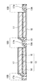
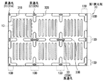
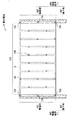
図1は本発明の第1の実施の形態に係る燃料電池1の断面構造を表すものである。図2は、図1の燃料電池を第1押え板の側からみたものである。燃料電池1は、例えば、携帯電話やPDA(Personal Digital Assistant;個人用携帯情報機器)などのモバイル機器、またはノート型PC(Personal Computer)に用いられる直接メタノール型燃料電池(DMFC;Direct Methanol Fuel Cell)である。この燃料電池1には、複数の接合体13が面内方向に連結した集合体が形成されている。
<First Embodiment>
[1. Configuration of Fuel Cell 1]
FIG. 1 shows a cross-sectional structure of a
接合体13は、電解質膜15を間にして燃料電極16と酸素電極14とが対向配置されたものである。この接合体13は、セパレータ(接続部材)17,18により、燃料電極16および酸素電極14のそれぞれの側から狭持されると共に、電気的に直列となるように接続方向D1に沿って複数接続されている。本実施の形態では、6つの接合体(集合体)が面内方向においてコの字型となるように連結している。
The joined
電解質膜15は、例えば、スルホン酸基(−SO3 H)を有するプロトン伝導材料により構成されている。プロトン伝導材料としては、ポリパーフルオロアルキルスルホン酸系プロトン伝導材料(例えば、デュポン社製「Nafion(登録商標)」)、ポリイミドスルホン酸などの炭化水素系プロトン伝導材料、またはフラーレン系プロトン伝導材料などが挙げられる。
The
燃料電極16および酸素電極14は、例えば、カーボンペーパーなどよりなる集電体に、白金(Pt)あるいはルテニウム(Ru)などの触媒を含む触媒層が形成された構成を有している。触媒層は、例えば、触媒を担持させたカーボンブラックなどの担持体をポリパーフルオロアルキルスルホン酸系プロトン伝導材料などに分散させたものにより構成されている。
The
このような接合体13の燃料電極16および酸素電極14の側にはそれぞれ、セパレータ17,18を介して、第1押え板10および第2押え板11が配置されている。接合体13の周辺領域13Dの選択的な位置に、第1押え板10の側から第2押え板11の側まで貫通した貫通孔12が設けられている。
A
第1押え板10および第2押え板11は、接合体13が形成されている領域と、その周辺領域13Dとに対向するように配置されている。これらの第1押え板10および第2押え板11により、連結された接合体13の物理的強度が保たれると共に、接合体13の各層および接合体13とセパレータ17,18との密着性が確保される。また、周辺領域13Dにおいて、第2押え板11とセパレータ17,18との間には、接合体13の外周に沿って、シール部19が形成されている。
The
これらの第1押え板10および第2押え板11は、例えばアルマイト処理されたアルミニウム(Al),ポリフェニレンスルフィドもしくはポリエーテルエーテルケトンなどのスーパーエンジニアリングプラスチックもしくはエンジニアリングプラスチック,セラミクス,または絶縁処理されたステンレス鋼などの金属材料により構成されている。また、図2に示したように、第1押え板10は、燃料電極16側に燃料を供給するための開口10Cを有しており、図示しない燃料タンクなどから燃料が供給されるようになっている。また、第2押え板11にも同様に、酸素電極14側に酸素(空気)を供給するための開口が設けられており、例えば外部と連通させて空気を取り込むことができるようになっている。なお、図2は、第1押え板10の平面構成を表すものであるが、第2押え板11の平面構成についても同様となっている。
The
貫通孔12は、燃料電池1の面内方向において例えば等間隔で設けられ、その断面形状が例えば直径dの円形となっている。すなわち、周辺領域13Dでは、第1押え板10、セパレータ17(セパレータ18)、シール部19および第2押え板11にはそれぞれ、貫通孔12に対応して直径dの円形状の開口(開口10A,17A,19A,11A)が形成されている。これらの開口10A,17A,19A,11Aは、互いに正対して配置され、かつ同一の形状となっていることが望ましい。後述の樹脂層20を形成し易くするためである。一方、周辺領域13Dにおいて、第1押え板10とセパレータ17(セパレータ18)との間は、上記開口10A,17A,19A,11Aと共に貫通孔12を形成する領域21(空隙)となっている。このような貫通孔12には、樹脂層20が埋設されている。
The through holes 12 are provided, for example, at equal intervals in the in-plane direction of the
また、第1押え板10および第2押え板11の貫通孔12に対応する領域の表面側(接合体13と反対側)には、開口10A,11Aよりも大きな面積の底面を有する凹部10B,11Bがそれぞれ設けられている。
Further, on the surface side of the region corresponding to the through
樹脂層20は、熱可塑性を有する樹脂材料、例えばポリプロピレン(PP)、ポリエチレン(PE)、ポリ塩化ビニル(PVC)、ABS樹脂(アクリロニトリル−ブタジエン−スチレン共重合体)、ナイロン、ポリアセタール(POM)、フッ素樹脂、ポリメチルペンテン(PMP)、ポリアクリロニトリル(PAN)、アクリレート系樹脂、シリコンゴム、クロロプレンゴム、フッ素ゴムなどにより構成されている。樹脂層20の構成材料としては、融点が例えば210°〜230°であることが望ましい。これは、樹脂層20を形成する際に、金型に溶融させた樹脂材料を流し込んだのちに冷却して固化させる射出成形法と異なり、冷却工程を経ないためである。また、メチルアルコールなどに対して耐性を有していることが望ましい。上記のような観点から、樹脂層20の構成材料としてはポリプロピレンが好適である。
The
セパレータ17,18は、隣接する接合体13を電気的に直列に接続する機能を有すると共に、接合体13の燃料電極16および酸素電極14にそれぞれ密着して配置され、燃料もしくは空気を供給する流路を形成している。このようなセパレータ17,18は、例えば、銅(Cu),ニッケル(Ni),チタン(Ti)またはステンレス鋼(SUS)などにより構成されている。また、燃料もしくは空気を供給するための開口(図示せず)を有しており、例えば、エキスパンドメタルなどのメッシュ類や、パンチングメタルなどにより構成されている。また、セパレータ17,18は、接合体13の周辺領域13Dにおいて、屈曲しており、この屈曲した部分と第2押え板11との間に、シール部19が設けられている。
The
シール部19は、例えばポリプロピレン、酸変性ポリプロピレン、ポリビニルアルコールおよびポリエチレンテレフタラート(PET)などにより構成されており、各接合体13の周辺領域13Dを封止して、側面から空気が進入することを抑制するものである。
The
この燃料電池1は、例えば、次のようにして製造することができる。
The
[2.燃料電池1の製造方法]
図3〜図9は、燃料電池1の製造方法を工程順に表したものである。まず、図3に示したように、複数の接合体13を連結した集合体を形成する。例えば、上述した材料よりなる電解質膜15を、上述した材料よりなる燃料電極16および酸素電極14の間に挟んで、熱圧着することにより接合体13を形成する。続いて、上述した材料よりなるセパレータ17,18を用意し、その一方の端部を屈曲させ、この屈曲した端部に上述した材料よりなるシール部19を形成する。続いて、セパレータ17を燃料電極16の側、セパレータ18を酸素電極14の側にそれぞれ対向させて配置し、熱圧着させる。このようにして、セパレータ17,18によって狭持された接合体13を複数形成し、これらを面内方向に連結する。この際、例えば隣接する接合体13において、一方の接合体13のセパレータ17の端部と他方の接合体13のセパレータ18の端部同士を、連結部170において連結するようにする。
[2. Manufacturing method of fuel cell 1]
3 to 9 show the manufacturing method of the
続いて、図4に示したように、各接合体13の周辺領域13Dの選択的な位置において、セパレータ17,18およびこれらの連結部170と、シール部19とに開口17A19Aを、例えばシートプレスやポンチ等により、それぞれ形成する。
Subsequently, as shown in FIG. 4, at a selective position of the
一方、第1押え板10および第2押え板11には、凹部11A,11Bを、例えばプレス、ハーフエッチング、拡散接合などにより形成したのち、この凹部10A,11Aの底面に、開口10A,10Bを、例えばプレスやフライス加工等により形成する。
On the other hand, after forming the
次いで、図5に示したように、連結された接合体13のセパレータ17(燃料電極16)側に第1押え板10を、セパレータ18(酸素電極14)側に第2押え板11を、開口10A,11A,17A,19A同士が対向するようにそれぞれ重ね合わせ、熱圧着させる。これにより、第1押え板10および第2押え板11によって、連結された接合体13が狭持されると共に、貫通孔12が形成される。こののち、第1押え板10の側に上型110、第2押え板11の側に下型111をそれぞれ密着するように配置する。上型110には、貫通孔12に対向する位置に、注入孔110Aが設けられており、下型111には、通気孔22が設けられている。
Next, as shown in FIG. 5, the
続いて、上述した材料の樹脂材料を溶融させた状態(樹脂20A)で、貫通孔12に流し込む、いわゆるメルトフロー注入法により、樹脂層20を形成する。すなわち、図6に示したように、例えば0.25〜0.35MPaの圧力下で、上型110の注入孔110Aから、樹脂20Aを流し込む。このとき、例えば図7に示したような治具120を用いて、複数の注入孔110Aに対して、同時に樹脂20Aを注入する。治具120には、樹脂20Aの注入口としてのスプルー112と、このスプルー112から注入された樹脂20Aの流路となる複数のランナー113と、各ランナー113の先端に設けられたゲート114とが設けられている。これら複数のランナー113では、スプルー112から各ランナー113の先端部分に設けられたゲート114までの経路の長さは、互いに等しくなっている。使用時には、この治具120のゲート114と、上型110の注入孔110Aとを対向させて設置し、スプルー112から樹脂20Aを注入する。これにより、注入された樹脂20Aは、各ランナー113に分散されて、各ゲート114から注入孔110Aへ到達するが、各注入孔110Aに対して均等かつ同時に注入される。
Subsequently, the
このように、上型110の各注入孔110Aに、樹脂20Aを同時に注入すると、樹脂20Aは、まず、第1押え板10の表面に形成された凹部10Bの形状に沿って流れ込む。また、燃料電極16の側から樹脂20Aを注入することにより、燃料電極16側の密閉性を高めることができる。
As described above, when the
続いて、図8に示したように、樹脂20Aの注入を進めていくと、凹部10Bに拡がった樹脂20Aは、第1押え板10の開口10A、領域21、セパレータ17,18の開口17A、シール部19の開口19Aおよび第2押え板11の開口11Aをこの順に通過して、第2押え板11の凹部11Bにまで達する。このとき、貫通孔12を流動する樹脂20Aは、上型110および下型111により密閉されているので、外部へ流出することはない。また、樹脂20Aの注入圧により内圧が高められるため、内部の気密性は保たれる。さらに、下型111に設けられた通気孔22により、内圧を調整して接合体13の内部破壊が回避されると共に、発生ガスの排出による各電極との反応が抑制される。なお、この際、樹脂20Aは、注入孔110Aに近い程、温度が高く、遠くなるに従って徐々に温度が低くなるため、注入孔110Aの表面付近では粘性が大きく、第2押え板11付近では粘性が小さくなっている。
Subsequently, as illustrated in FIG. 8, when the injection of the
次いで、図9に示したように、さらに樹脂20Aの注入を進めていくと、樹脂20Aは第2押え板11の凹部11B全体に流れ込んで拡がり、この凹部11Bから第1押え板10の凹部10Bにかけて順に硬化していく。この過程において、領域21の空隙部分にも樹脂20Aが充填されて硬化し、貫通孔12に樹脂層20が埋設される。このように、凹部10B,11Bに樹脂20Aが拡がって硬化することで、第1押え板10および第2押え板11により接合体13が加圧保持(締結)される。このとき、第1押え板10および第2押え板11にそれぞれ、凹部10B,11Bが設けられていることにより、各貫通孔12に対する樹脂20Aの注入量にばらつきがあった場合であっても、このばらつきが吸収され、均等に加圧され易くなる。最後に、所定量の樹脂20Aを注入したのち、加圧状態を保持したまま、樹脂注入経路を密閉する。以上により、図1に示した燃料電池1を完成する。
Next, as illustrated in FIG. 9, when the injection of the
次に、本実施の形態の作用、効果について説明する。 Next, the operation and effect of the present embodiment will be described.
[3.燃料電池1の作用]
上記燃料電池1では、第1押え板10およびセパレータ17を経て燃料電極16に燃料が供給される一方、第2押え板11およびセパレータ18を経て酸素電極14に酸素が供給されると、酸化還元反応を生じ、燃料がもっていた化学エネルギーが電気エネルギーに変換されて電力として取り出される。
[3. Operation of Fuel Cell 1]
In the
ここで、連結された接合体13を狭持する第1押え板10および第2押え板11の周辺領域13Dに、貫通孔12が設けられ、この貫通孔12に樹脂層20が埋設されていることにより、接合体13が締結され、加圧保持される。このように樹脂層20を用いることで、金属ねじによる締結に比べて締結スペースが小さくなると共に、接合体13に対する絶縁性を確保するためのスペースも不要となる。このため、特に面内方向に複数の接合体13を連結する場合において、複数の接合体13のそれぞれの周囲に締結スペースを確保することができ、燃料電池1の面内全体を均等に加圧することができる。
Here, a through
また、金属ねじを用いた場合には、発電による接合体の膨潤により締結力が弱まり、経時的に締結時の加圧状態を維持することが困難であるが、本実施の形態では、樹脂20の弾性により、締結後も所定の加圧状態が維持され易くなる。さらに、樹脂層20により燃料のリークが抑制される。
In addition, when a metal screw is used, the fastening force is weakened due to swelling of the joined body due to power generation, and it is difficult to maintain the pressurized state at the time of fastening over time. Due to this elasticity, a predetermined pressure state is easily maintained even after fastening. Further, fuel leakage is suppressed by the
また、上記燃料電池1の製造方法では、接合体13と周辺領域13Dとを、開口10A,11Aをそれぞれ有する第1押え板10および第2押え板11により挟み込み、第1押え板10の開口10Aに、溶融させた樹脂20Aを所定の圧力下で注入することにより、溶融した樹脂層20Aは、貫通孔12において第2押え板11の側から徐々に硬化していく。これにより、貫通孔12に樹脂層20が埋設される。このように、所定の圧力下において、溶融した樹脂20Aを貫通孔12に流し込み、自然冷却により固化させることで、接合体13の周辺領域13Dの選択的な位置にのみ樹脂層20が形成される。
In the method of manufacturing the
以上のように、本実施の形態では、接合体13と周辺領域13Dとに対向するように第1押え板10および第2押え板11を設け、周辺領域13Dに形成した貫通孔12に、樹脂層20を埋設するようにしたので、小型で安定した出力が可能な燃料電池1を実現することができる。
As described above, in the present embodiment, the
<変形例1>
図10は、上記実施の形態の変形例に係る燃料電池を第1押え板の側からみた平面図である。本変形例では、貫通孔の構成と、第1押え板および第2押え板の凹部の形状以外の構成は、上記実施の形態の燃料電池1と同様となっている。なお、本変形例では、図示しない第2押え板についても第1押え板30と同様の構成となっている。
<
FIG. 10 is a plan view of a fuel cell according to a modification of the above embodiment as viewed from the first presser plate side. In this modification, the configuration of the through hole and the configuration other than the shapes of the concave portions of the first press plate and the second press plate are the same as those of the
本変形例の燃料電池は、接合体13の周辺領域13Dに、貫通孔31,32,33を有している。貫通孔31,32,33はそれぞれ、面内の領域ごとに断面積が異なり、面内の内部領域では、端部領域(燃料電池の外周部分)よりも断面積が大きくなっている。すなわち、第1押え板30の平面形状が矩形状となっており、この四隅に設けられた貫通孔31、辺に対向する領域に設けられた貫通孔32、中央の領域に設けられた貫通孔33の順に断面積が大きくなっている。第1押え板30には、上記のような貫通孔31,32,33と等しい断面積の開口31A,32A,33Aが形成されており、貫通孔31,32,33の断面積よりも大きな底面積を有する凹部31A,32B,33Bが設けられている。
The fuel cell of the present modification has through
このように、貫通孔31,32,33の断面積を面内の領域に応じて異なるように形成することにより、燃料電池面内の反力に応じた締結が可能となる。一般に、面内方向に接合体を連結した集合体においては、全体の中央付近において反力が最も強く、端部領域ほど反力が弱まるため、厳密には中央と端部との間で均等な加圧保持が困難となる。本変形例では、貫通孔31,32,33の断面積を領域ごとに異なるようにすることで、上記のような反力に応じた保持力を与えることができる。よって、より均等な加圧保持が可能となる。
In this way, by forming the cross-sectional areas of the through
また、各貫通孔の断面積の大きさによって、引張り強度を任意に設定でき、締結後のトルク管理等が不要となる。さらに、均等加圧により、第1押え板30および第2押え板の厚みによらず、物理的な強度が確保され易くなるため、薄型化が可能となる。
Further, the tensile strength can be arbitrarily set according to the size of the cross-sectional area of each through hole, and torque management after fastening is not necessary. Furthermore, since the physical strength is easily ensured by the uniform pressure regardless of the thickness of the
なお、上記貫通孔の断面積の形状は特に限定されない。保持力は断面積の大きさによって決まるため、貫通孔の形状設計については自由度がある。また、変形例1では、反力に応じて締結するために、貫通孔の断面積の大きさを領域ごとに変化させる場合について説明したが、これに限定されず、例えば貫通孔の数を領域ごとに変化させ、貫通孔が端部領域よりも内部領域に密に配置されるようにしてもよい。このような構成であっても、反力に応じた樹脂締結が可能となり、上記変形例1と同等の効果を得ることができる。 The shape of the cross-sectional area of the through hole is not particularly limited. Since the holding force is determined by the size of the cross-sectional area, the shape of the through hole has a degree of freedom. Further, in the first modification, the case where the size of the cross-sectional area of the through hole is changed for each region in order to fasten it according to the reaction force is not limited to this. For example, the number of through holes is set to the region. The through holes may be arranged more densely in the inner region than in the end region. Even with such a configuration, it is possible to fasten the resin according to the reaction force, and it is possible to obtain the same effect as the first modification.
<第2の実施の形態>
[1.燃料電池2の構成]
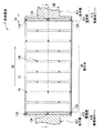
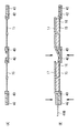
図11は、本発明の第2の実施の形態に係る燃料電池2を第1押え板10の側からみたものである。図12は、図11に示した燃料電池2のI−I線における矢視断面構造を表すものである。燃料電池2は、上記第1の実施の形態の燃料電池1と同様、直接メタノール型燃料電池であり、複数の接合体13が電気的に直列(以下、単に直列という)となるように接続された集合体(集合体130)を有するものである。但し、本実施の形態において、集合体130は矩形状の接合体13が直線状に9つ連結したものである。この集合体130を、第1押え板10と第2押え板11との間に挟み込んで締結するために、上記第1の実施の形態とは異なるパターンで複数の貫通孔12A,12Bが設けられている。本実施の形態では、このような構成において、特に外部接続用の電極端子41A,41Bについて詳細に説明する。
<Second Embodiment>
[1. Configuration of Fuel Cell 2]
FIG. 11 shows the fuel cell 2 according to the second embodiment of the present invention as viewed from the
(電極端子の構成)
集合体130は、平面形状が例えば矩形状となっている。この集合体130の接続方向D2における一端には、+(プラス)側の電極端子41A、他端には−(マイナス)側の電極端子41Bがそれぞれ取り付けられている。電極端子41Aはセルプレート18、電極端子41Bはセルプレート17をそれぞれ介して集合体130に接続されている。以下、集合体130の端部あるいは端辺といった場合には、集合体130の接続方向D2における端部あるいは端辺を示すものとする。
(Configuration of electrode terminal)
The
このような集合体130には、複数の貫通孔12A,12Bが設けられ、これらの貫通孔12A,12Bに樹脂層40が埋設されることにより樹脂締結がなされている。貫通孔12Aは、集合体130の両端、具体的には集合体130の四隅と端辺の中央付近とに、計6つ設けられている。このように、集合体130の両端において樹脂締結がなされていることが望ましい。集合体130を均等に加圧保持すると共に、物理的強度を確保し易くなるためである。集合体130の両端以外の領域のうち隣り合う接合体13同士の間の領域には、複数(ここでは18個)の貫通孔12Bが同程度の間隔で設けられている。なお、樹脂層40は、上記第1の実施の形態の樹脂層20と同様の材料により構成されている。
Such an
電極端子41Aは、集合体130の端辺に沿って延在する電極部410と、この電極部410の一部領域から外部へ向けて、電極部410の延在方向と非平行な方向に引き出された端子部411とから構成されている。本実施の形態では、端子部411は、電極部410の中央付近から、電極部410の延在方向に直交するように引き出されている。この電極端子41Aと同様、電極端子41Bも、集合体130の端辺に沿って延在する電極部412と、電極部412の一部から外部へ向けて引き出された端子部413とから構成されている。
The
電極端子41A,41Bを構成する材料としては、例えばチタン(Ti)、モリブデン(Mo)、タングステン(W)、金(Au)、銅(Cu)、黄銅、および金めっきを施した銅などが挙げられる。電極部410,412の幅B1は、例えば1mm〜3mm程度である。端子部411,413の幅B2は、電極部410,411の幅B1よりも広く、好ましくは3mm〜10mm程度である。
Examples of the material constituting the
このように、集合体130の両端には、締結のための貫通孔12Aと電極端子41A,41Bの電極部410,412との双方が設けられている。すなわち、集合体130の両端では、電極部410,412を貫通するように貫通孔12Aが設けられた構成となっている。
Thus, both ends of the
具体的には、図12に示したように、集合体130の一端(+側)では、第1押え板10と第2押え板11との間に、シール部19、セパレータ18、電極端子41A、チタンシート42およびシール部43が積層した構成となっている。これらの第1押え板10から第2押え板11までの全ての層を貫通するように貫通孔12Aが設けられている。集合体130の他端(−側)では、第1押え板10と第2押え板11との間に、シール部19、チタンシート42、シール部43、電極端子41Bおよびセパレータ17が積層され、これらの全ての層を貫通するように貫通孔12Aが設けられている。集合体130の両端以外の領域では、第1押え板10と第2押え板11との間に、セパレータ18、チタンシート42、シール部43およびセパレータ17が積層され、これら全ての層を貫通するように貫通孔12Bが設けられている。
Specifically, as shown in FIG. 12, at one end (+ side) of the
[2.燃料電池2の製造方法]
このような電極端子41A,41Bが取り付けられた燃料電池2は、例えば次のようにして製造することができる。まず、電解質膜15およびシール部43を所定の形状となるように裁断して貼り合わせたのち、加熱することにより、図13(A)に示したように、電解質膜15とシール部43とが連結した電解質シートを形成する。続いて、図13(B)に示したように、形成した電解質シートを裁断することにより、周辺にシール部43が設けられた電解質膜15を複数形成する。
[2. Manufacturing method of fuel cell 2]
The fuel cell 2 to which
次いで、図14(A)に示したように、周辺にシール部43が形成された電解質膜15を、電解質膜15に対応する領域に開口を有するチタンシート42上に位置合わせしてヒートシールすることにより、9つの電解質膜15をチタンシート42上で直線状に連結させる。
Next, as shown in FIG. 14A, the
続いて、図14(B)に示したように、連結した9つの電解質膜15のそれぞれに、燃料電極16およびセパレータ17を位置合わせしたのち、抵抗溶接により各セパレータ17の端部をチタンシート42に接合する。このとき、図15中の左端(−側端部)では、シール部43とセパレータ17との間に電極端子41Bを挟み込むようにする。
Subsequently, as shown in FIG. 14B, after the
次いで、図15(A)に示したように、9つの電解質膜15のそれぞれに、酸素電極14およびセパレータ18を位置合わせしたのち、抵抗溶接により各セパレータ18の端部をチタンシート42に接合する。このとき、図15中の右端(+側端部)では、シール部43とセパレータ17との間に電極端子41Aを挟み込むようにする。
Next, as shown in FIG. 15A, after the
続いて、図15(B)に示したように、酸素電極14、電解質膜15および燃料電極16をヒートプレスにより、接着させる。これにより、9つの接合体13が直列に接続された集合体130を形成する。
Subsequently, as shown in FIG. 15B, the
次いで、図16(A)に示したように、集合体130の右端において、セパレータ18、電極端子41A、チタンシート42およびシール部43を貫通するように、貫通孔12A1を例えばシートプレスやポンチ等により形成する。同様にして、集合体130の左端において、チタンシート42、シール部43、電極端子41Bおよびセパレータ17を貫通するように、貫通孔12A1を形成する。また、集合体130の両端以外の領域では、セパレータ18、チタンシート42、シール部43およびセパレータ17を貫通するように、貫通孔12B1を形成する。
Next, as shown in FIG. 16A, at the right end of the
続いて、図16(B)に示したように、貫通孔12A1,12B1に対応して開口および凹部11Bが設けられた第2押え板11上の周縁部に、シール部19を貼り合わせたのち、集合体130を重ね合わせ、ヒートプレスする。こののち、上記第1の実施の形態と同様にして、所定の開口および凹部が設けられた第1押え板10をセルプレート17の側に重ね合わせ、所定の条件下において樹脂を注入することにより、貫通孔12A,12Bに樹脂層40を埋設する。以上により、図11および図12に示した燃料電池2を完成する。
Subsequently, as shown in FIG. 16B, after the
[3.燃料電池2の作用]
燃料電池2では、上記第1の実施の形態の燃料電池1と同様、燃料電極16に燃料が供給される一方、酸素電極14に酸素が供給されると、酸化還元反応を生じ、燃料がもっていた化学エネルギーが電気エネルギーに変換されて電力を発生する。ここで、本実施の形態では、集合体130の両端に貫通孔12A、集合体130の両端以外の領域には貫通孔12Bがそれぞれ設けられ、これらの貫通孔12A,12Bに樹脂層40が埋設されている。このような樹脂による締結により、集合体130が第1押え板10と第2押え板11との間に狭持され、加圧保持される。
[3. Operation of Fuel Cell 2]
In the fuel cell 2, as in the
このような樹脂締結による集合体130において発生した電力は、集合体130の両端に取り付けられた電極端子41A,41Bを通じて外部へ取り出される。ここで、物理的強度等の観点から電極部410,412を貫通するように貫通孔12Aが形成され、この貫通孔12Aに樹脂層40が埋設されている。ところが、このように電極部410,412に貫通孔12Aを設けて樹脂層40を埋設した場合、電極部410,412の幅B1は1mm〜3mm程度と狭いため、加圧時などに電極部410,412が破断してしまうことがある。
The electric power generated in the
ここで、図17に、本実施の形態の変形例(変形例2)として、第1押え板10の側からみた燃料電池3の平面構成について示す。燃料電池3では、集合体130の両端に、外部へ電力を取り出すための電極端子44A,44Bが取り付けられている。この電極端子44A,44Bでは、集合体130の端辺に沿って電極部440,442が設けられ、この電極部440,442の一端を延長させるように端子部441,443が設けられている。すなわち、電極端子44A,44Bは、電極部440,442の一端から電極部440,442の延在方向と平行な方向に沿って端子部441,443が引き出された構成となっている。このように、電極端子44A,44Bにおいて端子部441,443の引き出し方向は、電極部440,442の延在方向と平行であってもよい。
Here, FIG. 17 shows a planar configuration of the
ところが、このような燃料電池3では、上述したような貫通孔12Aに起因する電極部440,442の破断が生じた場合に、集合体130から電力を安定して取り出しにくくなってしまう。また、電極部440,442における導電抵抗によって発熱が生じる虞もある。
However, in such a
これに対し、本実施の形態では、電極部410,412の延在方向と非平行な方向に端子部411,413が引き出されていることにより、仮に貫通孔12Aによって電極部410,412の破断が生じた場合にも、安定して電力が取り出される。また、端子部411,413は、例えば電極部410,412の中央付近において、幅B1よりも大きな幅B2となるように設けられている。これにより、電極部410,412の幅B1によらず、端子部411,413の断面積を確保することができるため、端子部411,413の物理的強度が保持されると共に、端子部411,413における導電抵抗が小さくなる。
On the other hand, in the present embodiment, the
以上のように、本実施の形態では、集合体130の両端に貫通孔12Aを設けると共に、外部へ電力を取り出すための電極端子41A,41Bを設けたので、集合体130を樹脂締結する際に、物理的強度を確保しつつ外部への電力を取り出すことができる。特に、電極端子41A,41Bにおいて、電極部410,412の延在方向と非平行な方向に端子部411,413を引き出すようにすれば、上記第1の実施の形態と同等の効果を得るだけでなく、より安定して電力を取り出すことができる。また、導電抵抗による熱の発生を抑制することも可能となる。
As described above, in the present embodiment, since the through
なお、本実施の形態では、9つの接合体を直列に接続した集合体130を例に挙げて、外部へ電力を取り出すための電極端子41A,41Bについて説明したが、このような電極端子構造は、上記第1の実施の形態および変形例1にも適用可能である。また逆に、本実施の形態においても、上記変形例1のように貫通孔の断面積を集合体面内の領域ごとに変化させ、より均等な加圧保持を実現するようにしてもよい。
In this embodiment, the
<変形例3>
図18は、上記第2の実施の形態の変形例(変形例3)に係る燃料電池4を第1押え板10の側からみたものである。本変形例では、上記第2の実施の形態と同様、集合体130の両端に取り付けられた電極端子45A,45Bにおいて、電極部450,452は、集合体130の端辺に沿って設けられ、この電極部450,452を貫通するように貫通孔12Aが形成されている。また、端子部451,453についても、電極部450,452の延在方向と非平行な方向(直交する方向)に引き出されている。
<
FIG. 18 is a view of the fuel cell 4 according to a modification (Modification 3) of the second embodiment as viewed from the
但し、本変形例では、端子部451,453が電極部450,452の隣り合う貫通孔12A同士の間の領域から引き出された構成となっている。電極部450,452は、上記第2の実施の形態の電極部410,412と同等の幅B1を有し、端子部451,543の幅B3は、例えば3mm〜10mmである。電極端子45A,45Bの構成材料については、上記第2の実施の形態の電極端子41A,41Bと同様である。また、これらの電極端子45A,45B以外は、上記第2の実施の形態と同様の構成となっている。
However, in this modification, the
このように、電極端子45A,45Bにおいて、端子部451,453は、電極部450,452の隣り合う貫通孔12A同士の間の領域から、電極部450,452の延在方向と非平行な方向に引き出されていてもよい。これにより、上述したような貫通孔12Aに起因する電極部450,452の破断が生じた場合であっても、安定して電力を取り出すことができる。また、図17に示した燃料電池3に比べ、導電抵抗による発熱を抑制することが可能となる。よって、上記第2の実施の形態とほぼ同等の効果を得ることができる。
Thus, in the electrode terminals 45A and 45B, the
<変形例4>
図19は、上記第2の実施の形態の変形例(変形例4)に係る燃料電池5を第1押え板10の側からみたものである。本変形例では、集合体130の両端に取り付けられた電極端子46A,46Bにおいて、電極部460,462は、上記第2の実施の形態と同様、集合体130の端辺に沿って設けられ、この電極部460,462を貫通するように貫通孔12Aが形成されている。但し、本変形例では、幅B1の電極部460,462の両端から、電極部460,462の延在方向と平行な方向に端子部(端子部461A,461B,463A,463B)が電極部460,462と同じ幅B1で引き出されている。電極端子46A,46Bの構成材料については、上記第2の実施の形態の電極端子41A,41Bと同様である。なお、これらの電極端子46A,46B以外は、上記第2の実施の形態と同様の構成となっている。
<Modification 4>
FIG. 19 shows the fuel cell 5 according to a modification (Modification 4) of the second embodiment as viewed from the
このように、電極端子46A,46Bにおいて、端子部461A,461B,463A,463Bは、電極部460,462の両端から、電極部460,462の延在方向と平行な方向に引き出されていてもよい。これにより、図17に示した燃料電池3のように端子部を電極部の一端からのみ引き出した構成に比べ、安定して電力を取り出すことができると共に、導電抵抗による発熱を抑制することが可能となる。よって、上記第2の実施の形態とほぼ同等の効果を得ることができる。
As described above, in the
以上、実施の形態および変形例を挙げて本発明を説明したが、本発明は、上記実施の形態等に限定されるものではなく、種々変形することができる。例えば、上記実施の形態では、電解質膜15,燃料電極16および酸素電極14の構成について具体的に説明したが、他の構造または他の材料により構成するようにしてもよい。
While the present invention has been described with reference to the embodiments and modifications, the present invention is not limited to the above-described embodiments and the like, and various modifications can be made. For example, in the above-described embodiment, the configuration of the
また、上記実施の形態等では、複数の接合体を面内方向に平面積層する場合を例に挙げて説明したが、これに限定されず、垂直方向に積層した構成にも適用可能である。また、上記実施の形態等では、6つの接合体をコの字型に接続した構成や、9つの接合体を直線状に接続した構成を例に挙げて説明したが、接合体の個数や接続方向はこれに限定されず、複数の接合体が電気的に直列となるように接続されていればよい。 Moreover, in the said embodiment etc., although the case where the some laminated body was planarly laminated in the in-plane direction was mentioned as an example, it demonstrated and it was not limited to this, It is applicable also to the structure laminated | stacked to the perpendicular direction. Further, in the above-described embodiment and the like, the configuration in which six joined bodies are connected in a U-shape or the configuration in which nine joined bodies are connected in a straight line is described as an example. The direction is not limited to this, and it is only necessary that the plurality of joined bodies be connected in series.
更に、上記実施の形態等では、シール部を第2押え板側に配置して、各接合体の酸素電極側の領域を封止するようにしたが、このシール部は第1押え板側に配置して、燃料電極側の領域を封止するようにしてもよい。さらに、各接合体の周囲にシール部を設けた構成を例に挙げて説明したが、シール部を燃料電池の外周部のみに設けるようにしてもよい。 Furthermore, in the above-described embodiment and the like, the seal portion is arranged on the second presser plate side so as to seal the region on the oxygen electrode side of each joined body, but this seal portion is on the first presser plate side. It may be arranged to seal the region on the fuel electrode side. Further, the configuration in which the seal portion is provided around each joined body has been described as an example, but the seal portion may be provided only on the outer peripheral portion of the fuel cell.
また、本発明は、DMFCのほか、水素を燃料とした固体高分子型燃料電池,ダイレクトエタノール型燃料電池あるいはジメチルエーテル型燃料電池など、他の形態の燃料電池にも適用可能である。 In addition to DMFC, the present invention can be applied to other types of fuel cells such as a solid polymer fuel cell using hydrogen as a fuel, a direct ethanol fuel cell, or a dimethyl ether fuel cell.
1〜5…燃料電池、10…第1押え板、10A…開口、10B…凹部、11…第2押え板、11A…開口、11B…凹部、12,12A,12B…貫通孔、13…接合体、14…酸素電極、15…電解質膜、16…燃料電極、17,18…セパレータ、19…シール部、20,40…樹脂層,41A,41B,44A,44B,45A,45B,46A,46B…電極端子。 DESCRIPTION OF SYMBOLS 1-5 ... Fuel cell, 10 ... 1st press plate, 10A ... Opening, 10B ... Recessed part, 11 ... 2nd presser plate, 11A ... Opening, 11B ... Recessed part, 12, 12A, 12B ... Through-hole, 13 ... Assembly , 14 ... oxygen electrode, 15 ... electrolyte membrane, 16 ... fuel electrode, 17, 18 ... separator, 19 ... seal part, 20, 40 ... resin layer, 41A, 41B, 44A, 44B, 45A, 45B, 46A, 46B ... Electrode terminal.
Claims (20)
前記接合体の前記燃料電極および前記酸素電極の側にそれぞれ設けられ、前記接合体およびその周辺領域に対向して配置された一対の押え板と、
一方の押え板から前記接合体の周辺領域を介して他方の押え板まで貫通する貫通孔と、
前記貫通孔に埋設された樹脂層と
を備えた燃料電池。 A joined body in which a fuel electrode and an oxygen electrode are arranged to face each other with an electrolyte membrane interposed therebetween;
A pair of press plates provided on the fuel electrode and oxygen electrode sides of the joined body, respectively, and disposed to face the joined body and its peripheral region;
A through-hole penetrating from one presser plate to the other presser plate through a peripheral region of the joined body,
A fuel cell comprising: a resin layer embedded in the through hole.
請求項1に記載の燃料電池。 The fuel cell according to claim 1, wherein a plurality of the joined bodies are arranged in an in-plane direction.
請求項2に記載の燃料電池。 The fuel cell according to claim 2, wherein the through hole is provided in a peripheral region of each joined body.
請求項3に記載の燃料電池。 The fuel cell according to claim 3, wherein a cross-sectional area of the through hole is larger in an inner region than end regions of the pair of presser plates.
前記貫通孔の断面積は、前記矩形の四隅において最も小さくなっている
請求項4に記載の燃料電池。 The planar shape of the pair of presser plates is a rectangle,
The fuel cell according to claim 4, wherein a cross-sectional area of the through hole is smallest at four corners of the rectangle.
請求項3に記載の燃料電池。 The fuel cell according to claim 3, wherein the through holes are provided closer to an inner region than end regions of the pair of presser plates.
請求項2に記載の燃料電池。 The fuel cell according to claim 2, further comprising a connecting member that connects the joined bodies and has an opening in a region corresponding to the through hole.
前記集合体の接続方向における端部に連結されると共に外部へ電力を取り出す電極端子を備えた
請求項7に記載の燃料電池。 An assembly is configured by electrically connecting a plurality of joined bodies in series,
The fuel cell according to claim 7, further comprising an electrode terminal connected to an end portion in the connection direction of the assembly and taking out electric power to the outside.
請求項8に記載の燃料電池。 The fuel cell according to claim 8, wherein the through hole also penetrates the electrode terminal at an end of the assembly.
前記集合体の端辺に沿って延在する電極部と、
前記電極部の一部から外部へ向けて引き出された端子部とを有する
請求項9に記載の燃料電池。 The electrode terminal is
An electrode portion extending along an edge of the assembly;
The fuel cell according to claim 9, further comprising: a terminal portion that is drawn outward from a part of the electrode portion.
請求項10に記載の燃料電池。 The fuel cell according to claim 10, wherein the terminal portion is drawn in a direction non-parallel to the extending direction of the electrode portion.
請求項11に記載の燃料電池。 The fuel cell according to claim 11, wherein the terminal portion is drawn out with a larger width than the electrode portion in a plane of the assembly.
前記端子部は、前記電極部に対応する領域の複数の貫通孔のうち隣接する貫通孔同士の間から引き出されている
請求項11に記載の燃料電池。 A plurality of the through holes are provided in a region corresponding to the electrode part,
The fuel cell according to claim 11, wherein the terminal portion is led out from between adjacent through holes among a plurality of through holes in a region corresponding to the electrode portion.
請求項7に記載の燃料電池。 The fuel cell according to claim 7, further comprising an adhesive layer having an opening in a region corresponding to the through hole between the one pressing plate and the connection member in a peripheral region of the joined body.
請求項1に記載の燃料電池。 2. The fuel cell according to claim 1, wherein a concave portion having a bottom surface having a larger area than the through hole is provided on a surface side of a region corresponding to the through hole of the pair of presser plates.
各開口の形状は、互いに等しくなっている
請求項1に記載の燃料電池。 Each of the pair of presser plates has an opening that forms a part of the through hole,
The fuel cell according to claim 1, wherein the shapes of the openings are equal to each other.
前記接合体およびその周辺領域を、前記周辺領域において互いに対向する開口をそれぞれ有する一対の押え板により挟み込み、一方の押え板の開口に、溶融させた熱可塑性の樹脂材料を所定の圧力下で注入する工程と
を含む燃料電池の製造方法。 Forming a joined body in which the fuel electrode and the oxygen electrode are arranged to face each other with the electrolyte membrane interposed therebetween;
The joined body and its peripheral region are sandwiched between a pair of press plates each having an opening facing each other in the peripheral region, and a molten thermoplastic resin material is injected into one press plate under a predetermined pressure. A process for producing a fuel cell, comprising:
請求項17に記載の燃料電池の製造方法。 The method of manufacturing a fuel cell according to claim 17, wherein the resin material is injected into an opening of a presser plate on the fuel electrode side of the pair of presser plates.
一方の押え板の複数の開口に同時に前記樹脂材料を注入する
請求項17に記載の燃料電池の製造方法。 A plurality of openings are formed in each of the pair of presser plates,
The fuel cell manufacturing method according to claim 17, wherein the resin material is simultaneously injected into a plurality of openings of one presser plate.
請求項17に記載の燃料電池の製造方法。
The method for manufacturing a fuel cell according to claim 17, wherein a recess having a bottom surface having a larger area than the through hole is formed on a surface side of a region corresponding to the through hole of the pair of presser plates.
Priority Applications (6)
| Application Number | Priority Date | Filing Date | Title |
|---|---|---|---|
| JP2008313153A JP5476708B2 (en) | 2008-06-13 | 2008-12-09 | Fuel cell and fuel cell manufacturing method |
| US12/997,741 US20110097644A1 (en) | 2008-06-13 | 2009-06-12 | Fuel cell and method of manufacturing fuel cell |
| BRPI0914864A BRPI0914864A2 (en) | 2008-06-13 | 2009-06-12 | fuel cell, and method for manufacturing fuel cell. |
| RU2010150783/07A RU2474930C2 (en) | 2008-06-13 | 2009-06-12 | Fuel element and method to manufacture fuel element |
| CN200980121776.6A CN102057527B (en) | 2008-06-13 | 2009-06-12 | Fuel cell and fuel cell manufacturing method |
| PCT/JP2009/060743 WO2009151113A1 (en) | 2008-06-13 | 2009-06-12 | Fuel cell and fuel cell manufacturing method |
Applications Claiming Priority (3)
| Application Number | Priority Date | Filing Date | Title |
|---|---|---|---|
| JP2008155140 | 2008-06-13 | ||
| JP2008155140 | 2008-06-13 | ||
| JP2008313153A JP5476708B2 (en) | 2008-06-13 | 2008-12-09 | Fuel cell and fuel cell manufacturing method |
Publications (2)
| Publication Number | Publication Date |
|---|---|
| JP2010021129A true JP2010021129A (en) | 2010-01-28 |
| JP5476708B2 JP5476708B2 (en) | 2014-04-23 |
Family
ID=41416816
Family Applications (1)
| Application Number | Title | Priority Date | Filing Date |
|---|---|---|---|
| JP2008313153A Expired - Fee Related JP5476708B2 (en) | 2008-06-13 | 2008-12-09 | Fuel cell and fuel cell manufacturing method |
Country Status (6)
| Country | Link |
|---|---|
| US (1) | US20110097644A1 (en) |
| JP (1) | JP5476708B2 (en) |
| CN (1) | CN102057527B (en) |
| BR (1) | BRPI0914864A2 (en) |
| RU (1) | RU2474930C2 (en) |
| WO (1) | WO2009151113A1 (en) |
Cited By (2)
| Publication number | Priority date | Publication date | Assignee | Title |
|---|---|---|---|---|
| JP2012109073A (en) * | 2010-11-16 | 2012-06-07 | Fuji Electric Co Ltd | Cell structure of fuel cell |
| WO2020022643A1 (en) * | 2018-07-26 | 2020-01-30 | 주식회사 엘지화학 | Cooling efficiency-enhanced battery module and battery pack comprising same |
Families Citing this family (4)
| Publication number | Priority date | Publication date | Assignee | Title |
|---|---|---|---|---|
| DE102010023566A1 (en) * | 2010-06-10 | 2011-12-15 | Fraunhofer-Gesellschaft zur Förderung der angewandten Forschung e.V. | Fuel cell and fuel cell stack |
| DE102015225351A1 (en) * | 2015-12-16 | 2017-06-22 | Bayerische Motoren Werke Aktiengesellschaft | Method for producing a power supply unit |
| KR20170126715A (en) * | 2016-05-10 | 2017-11-20 | 주식회사 미코 | Fuel cell stack structure |
| JP7017483B2 (en) * | 2018-07-20 | 2022-02-08 | トヨタ自動車株式会社 | Fuel cell manufacturing method and fuel cell |
Citations (2)
| Publication number | Priority date | Publication date | Assignee | Title |
|---|---|---|---|---|
| JP2001338673A (en) * | 2000-05-30 | 2001-12-07 | Nok Corp | Fuel cell separator assembly seal structure |
| JP2006221849A (en) * | 2005-02-08 | 2006-08-24 | Hitachi Maxell Ltd | Liquid fuel battery |
Family Cites Families (12)
| Publication number | Priority date | Publication date | Assignee | Title |
|---|---|---|---|---|
| JP2994914B2 (en) * | 1993-07-16 | 1999-12-27 | 三洋電機株式会社 | Fuel cell |
| JPH087915A (en) * | 1994-06-22 | 1996-01-12 | Toyota Motor Corp | Fuel cell and manufacture of fuel cell |
| JP3769958B2 (en) * | 1998-12-24 | 2006-04-26 | 三菱電機株式会社 | Fuel cell |
| US6686079B2 (en) * | 2000-05-17 | 2004-02-03 | Schlumberger Technology Corporation | Fuel cell for downhole power systems |
| JP4035055B2 (en) * | 2001-04-23 | 2008-01-16 | Nok株式会社 | Fuel cell and manufacturing method thereof |
| RU2198452C1 (en) * | 2001-08-21 | 2003-02-10 | Государственное унитарное предприятие "Компания МЭТИС" | Method for assembling diaphragm-electrode unit |
| TWI251954B (en) * | 2003-07-29 | 2006-03-21 | Ind Tech Res Inst | Flat fuel cell assembly and fabrication thereof |
| JP4515233B2 (en) * | 2004-11-24 | 2010-07-28 | 本田技研工業株式会社 | Fuel cell and cell fastening pin |
| JP2007227317A (en) * | 2006-02-27 | 2007-09-06 | Hitachi Ltd | Fuel cell, battery mounting member, and electronic equipment that mounts it |
| JP5130665B2 (en) * | 2006-06-21 | 2013-01-30 | 株式会社日立製作所 | Fuel cell and information electronic device mounted on fuel cell |
| TWI311830B (en) * | 2006-06-28 | 2009-07-01 | Nan Ya Printed Circuit Board Corporatio | Fuel cell module utilizing wave-shaped flow board |
| KR20080104566A (en) * | 2007-05-28 | 2008-12-03 | 삼성에스디아이 주식회사 | Stack for fuel cell |
-
2008
- 2008-12-09 JP JP2008313153A patent/JP5476708B2/en not_active Expired - Fee Related
-
2009
- 2009-06-12 BR BRPI0914864A patent/BRPI0914864A2/en not_active IP Right Cessation
- 2009-06-12 CN CN200980121776.6A patent/CN102057527B/en not_active Expired - Fee Related
- 2009-06-12 WO PCT/JP2009/060743 patent/WO2009151113A1/en active Application Filing
- 2009-06-12 RU RU2010150783/07A patent/RU2474930C2/en not_active IP Right Cessation
- 2009-06-12 US US12/997,741 patent/US20110097644A1/en not_active Abandoned
Patent Citations (2)
| Publication number | Priority date | Publication date | Assignee | Title |
|---|---|---|---|---|
| JP2001338673A (en) * | 2000-05-30 | 2001-12-07 | Nok Corp | Fuel cell separator assembly seal structure |
| JP2006221849A (en) * | 2005-02-08 | 2006-08-24 | Hitachi Maxell Ltd | Liquid fuel battery |
Cited By (5)
| Publication number | Priority date | Publication date | Assignee | Title |
|---|---|---|---|---|
| JP2012109073A (en) * | 2010-11-16 | 2012-06-07 | Fuji Electric Co Ltd | Cell structure of fuel cell |
| WO2020022643A1 (en) * | 2018-07-26 | 2020-01-30 | 주식회사 엘지화학 | Cooling efficiency-enhanced battery module and battery pack comprising same |
| JP2021504893A (en) * | 2018-07-26 | 2021-02-15 | エルジー・ケム・リミテッド | Battery module with improved cooling efficiency and battery pack containing it |
| JP7055203B2 (en) | 2018-07-26 | 2022-04-15 | エルジー エナジー ソリューション リミテッド | Battery module with improved cooling efficiency and battery pack containing it |
| US11476512B2 (en) | 2018-07-26 | 2022-10-18 | Lg Energy Solution, Ltd. | Cooling efficiency-enhanced battery module and battery pack comprising same |
Also Published As
| Publication number | Publication date |
|---|---|
| US20110097644A1 (en) | 2011-04-28 |
| CN102057527B (en) | 2014-07-16 |
| JP5476708B2 (en) | 2014-04-23 |
| CN102057527A (en) | 2011-05-11 |
| RU2010150783A (en) | 2012-06-20 |
| RU2474930C2 (en) | 2013-02-10 |
| BRPI0914864A2 (en) | 2015-11-03 |
| WO2009151113A1 (en) | 2009-12-17 |
Similar Documents
| Publication | Publication Date | Title |
|---|---|---|
| JP5476708B2 (en) | Fuel cell and fuel cell manufacturing method | |
| JP5564623B1 (en) | Solid polymer electrolyte fuel cell and electrolyte membrane-electrode-frame assembly | |
| US10044047B2 (en) | Electrode-membrane-frame assembly, method for producing the same, and fuel cell | |
| JP2013125680A (en) | Manufacturing method of electrolyte membrane/electrode structure with resin film for fuel cell | |
| JP2008171613A (en) | Fuel cells | |
| JP2008108677A (en) | Electrochemical device | |
| JP6432398B2 (en) | Fuel cell single cell | |
| JP5900034B2 (en) | Fuel cell and fuel cell manufacturing method | |
| JP2005183210A (en) | Fuel cell sealing structure | |
| JP2009104882A (en) | Fuel cell | |
| JP6681537B2 (en) | Joined body, fuel cell using the joined body, and method for disassembling the same | |
| JP2009123381A (en) | Electrolyte membrane structure of solid polymer fuel cell and its manufacturing method | |
| JP5179093B2 (en) | Fuel cell stack | |
| US11177485B2 (en) | Terminal plate for fuel cell | |
| JP2005150104A (en) | Mold for fuel cell separator, manufacturing method of fuel cell separator, the fuel cell separator, manufacturing apparatus of the fuel cell separator, and fuel cell | |
| JP2008204636A (en) | Injection mold and manufacturing method for manufacturing seal-integrated membrane electrode assembly | |
| JP2019139993A (en) | Fuel cell module and manufacturing method thereof | |
| JP2022048654A (en) | Manufacturing method of fuel battery cell | |
| JP7302544B2 (en) | Fuel cell manufacturing method | |
| JP4826159B2 (en) | Fuel cell separator and seal molding method thereof | |
| JP5282871B2 (en) | Fuel cell and manufacturing method thereof | |
| JP2023538306A (en) | Hybrid bipolar plate and method of making it | |
| JP2006079856A (en) | Fuel cell and its manufacturing method | |
| JP2020024794A (en) | Manufacturing apparatus for fuel battery cell | |
| JP2022126078A (en) | Manufacturing method for fuel cell, and fuel cell |
Legal Events
| Date | Code | Title | Description |
|---|---|---|---|
| A621 | Written request for application examination |
Free format text: JAPANESE INTERMEDIATE CODE: A621 Effective date: 20111104 |
|
| A131 | Notification of reasons for refusal |
Free format text: JAPANESE INTERMEDIATE CODE: A131 Effective date: 20130903 |
|
| A521 | Written amendment |
Free format text: JAPANESE INTERMEDIATE CODE: A523 Effective date: 20131025 |
|
| A131 | Notification of reasons for refusal |
Free format text: JAPANESE INTERMEDIATE CODE: A131 Effective date: 20131113 |
|
| A521 | Written amendment |
Free format text: JAPANESE INTERMEDIATE CODE: A523 Effective date: 20131210 |
|
| TRDD | Decision of grant or rejection written | ||
| A01 | Written decision to grant a patent or to grant a registration (utility model) |
Free format text: JAPANESE INTERMEDIATE CODE: A01 Effective date: 20140114 |
|
| A61 | First payment of annual fees (during grant procedure) |
Free format text: JAPANESE INTERMEDIATE CODE: A61 Effective date: 20140127 |
|
| LAPS | Cancellation because of no payment of annual fees |