JP2010020896A - Information recording device and method, program storing medium, and program - Google Patents
Information recording device and method, program storing medium, and program Download PDFInfo
- Publication number
- JP2010020896A JP2010020896A JP2009212164A JP2009212164A JP2010020896A JP 2010020896 A JP2010020896 A JP 2010020896A JP 2009212164 A JP2009212164 A JP 2009212164A JP 2009212164 A JP2009212164 A JP 2009212164A JP 2010020896 A JP2010020896 A JP 2010020896A
- Authority
- JP
- Japan
- Prior art keywords
- area
- information
- recorded
- unit
- file
- Prior art date
- Legal status (The legal status is an assumption and is not a legal conclusion. Google has not performed a legal analysis and makes no representation as to the accuracy of the status listed.)
- Granted
Links
Images


Abstract
Description
本発明は、情報記録装置および方法、プログラム格納媒体、並びにプログラムに関し、特に、FSの更新や追加が頻繁に発生しても、必要に応じてFSの記録領域を、ファイルの記録領域の一部を分割して設定できるようにし、さらに、FSが散在した状態になっても、最適化処理により1に纏めることで、記録媒体に記録された情報を高速に読み出し、または、書き込み可能にし、また、TDMAの消費を低減させると共に、論理上書きが予め頻繁に使用されるような場合、TDMAを大きめに設定してフォーマットすることで、TDMAを頻繁に更新できるようにした情報記録装置および方法、プログラム格納媒体、並びにプログラムに関する。 The present invention relates to an information recording apparatus and method, a program storage medium, and a program, and in particular, even if FS updating or addition frequently occurs, an FS recording area is set as a part of a file recording area as necessary. In addition, even if the FS is scattered, the information can be read or written at high speed by collecting the information into 1 by the optimization process. An information recording apparatus, method, and program that reduce TDMA consumption and enable TDMA to be updated frequently by setting TDMA to a larger size when logical overwriting is frequently used in advance. The present invention relates to a storage medium and a program.
大容量の記録媒体にファイルを記録する技術が普及しつつある。 A technique for recording a file on a large-capacity recording medium is spreading.
また、このような大容量の記録媒体にファイルを記録する様々なフォーマットが提案されている。 Various formats for recording files on such a large-capacity recording medium have been proposed.
例えば、DVD(Digital Versatile Disc)で使用されているUDF(Universal Disc Format)などがある(例えば、非特許文献1参照)。 For example, there is a UDF (Universal Disc Format) used in a DVD (Digital Versatile Disc) (for example, see Non-Patent Document 1).
ところで、上述のUDF規格(Ver2.50)においては、ファイルシステム情報をメタデータパーティションと呼ばれる領域にまとめて配置し、メタデータパーティション内の論理アドレス上に配置する機能が追加されている。 By the way, in the above-mentioned UDF standard (Ver2.50), a function is added in which file system information is collectively arranged in an area called a metadata partition and arranged on a logical address in the metadata partition.
しかしながら、ライトアットワンスメディア(1回のみの記録が可能な記録媒体)においては、記録されているファイルやファイルシステムが更新されると、記録媒体上の新たな領域に記録されることになり、対応して論理アドレスを書き換える必要がある。 However, in write-at-once media (recording media that can be recorded only once), when the recorded file or file system is updated, it is recorded in a new area on the recording medium. Correspondingly, it is necessary to rewrite the logical address.
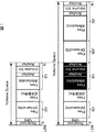
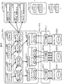
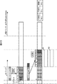
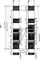
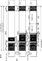
例えば、UDF規格(Ver2.50)に対応したBlu-Ray Disc(以下、BDとも称する)の場合、ファイルやファイルシステム情報は、図1の上段で示されるように記録される。ここで、図1は、BDのライトアットワンスメディア(以下、Blu-Ray Disc-Recordable:BD-Rとも称する)上の記録状態の例を示している。図1においては、図中左からLSN(Logical Sector Number:論理セクタ番号(=論理アドレス))が設定されており、図1の上段においては、ボリュームスペースとして設定されている領域は、0乃至Nとなっている。LSNの先頭位置の「Reserved」と記述されている領域は、予約領域を示す。「VRS(Volume Recognition Sequence)」と記述されている領域は、ファイルシステム種別を認識するための情報が記録されている領域を示す。「Files(Stream+DB)」と記述されている領域は、BDにストリームデータを記録または再生するためのアプリケーションプログラムにより記録または再生されるストリームデータと、その再生処理に用いられるデータベース情報が記録されている領域を示す。「Files(BD管理外)」と記述されている領域は、BDにストリームデータを記録または再生するためのアプリケーションプログラム以外のプログラムにより記録されたデータが記録されている領域を示す。「FS(Metadata)」と記述されている領域は、メタデータとしてファイルシステム情報が記録された領域を示す。「Anchor」と記述されている2の領域は、アンカ情報が記録されている領域を示す。「Volume Str.(Volume Structure)」と記述された領域は、ボリューム構造の情報が記録されている領域を示す。尚、「Files(Stream+DB)」と記述されている領域は、領域B0とも称するものとする。また、「FS」、「Anchor」、および、「Volume Str.」と示された領域は、まとめて領域B1とも称する。 For example, in the case of a Blu-Ray Disc (hereinafter also referred to as BD) corresponding to the UDF standard (Ver2.50), files and file system information are recorded as shown in the upper part of FIG. Here, FIG. 1 shows an example of a recording state on a BD write-at-once medium (hereinafter also referred to as Blu-Ray Disc-Recordable: BD-R). In FIG. 1, LSN (Logical Sector Number: logical address) is set from the left in the figure. In the upper part of FIG. 1, the areas set as volume spaces are 0 to N. It has become. An area described as “Reserved” at the head position of the LSN indicates a reserved area. An area described as “VRS (Volume Recognition Sequence)” indicates an area in which information for recognizing the file system type is recorded. In an area described as “Files (Stream + DB)”, stream data recorded or reproduced by an application program for recording or reproducing stream data on a BD and database information used for the reproduction processing are recorded. Indicates the area. An area described as “Files (out of BD management)” indicates an area in which data recorded by a program other than an application program for recording or reproducing stream data on a BD is recorded. An area described as “FS (Metadata)” indicates an area in which file system information is recorded as metadata. A second area described as “Anchor” indicates an area in which anchor information is recorded. An area described as “Volume Str. (Volume Structure)” indicates an area in which volume structure information is recorded. The area described as “Files (Stream + DB)” is also referred to as area B0. The areas indicated as “FS”, “Anchor”, and “Volume Str.” Are also collectively referred to as area B1.
例えば、図1の上段で示されている状態のBD-Rに、ストリームデータが追記されて、そのデータベース情報が更新された場合、BD-Rには、図1の下段で示されるように、情報が記録されることになる。 For example, when stream data is added to the BD-R in the state shown in the upper part of FIG. 1 and the database information is updated, the BD-R has the following information as shown in the lower part of FIG. Information will be recorded.
すなわち、領域B0に記述された情報に追記された、新たなストリームデータと、その再生用のデータベース情報とが、領域B0'に記録されることになる。さらに、その後段の領域B0'に、新たに情報が追記されることにより更新されたファイルシステム情報(以降においては、FSとも称する)と、そのFSに対応するアンカ情報とボリューム構造の情報が領域B2に記録されることになる。このとき、領域B1に記録されていた、FS情報と、そのFSに対応するアンカ情報とボリューム構造の情報は、読出不能な状態とされる。
ところで、ライトアットワンスメディア(1回のみの記録が可能な記録媒体)においては、記録されているファイルやファイルシステム(FSとも称する)が更新されると、記録媒体上の新たな領域に記録されることになり、対応して論理アドレスを書き換える必要がある。 By the way, in write-at-once media (recording media that can be recorded only once), when a recorded file or file system (also referred to as FS) is updated, it is recorded in a new area on the recording medium. Therefore, it is necessary to rewrite the logical address correspondingly.
このため、UDFのようなファイルフォーマットに規格として設けられている、代替領域やUser領域に更新されたファイルシステム情報(FS)を、更新前のファイルシステム情報の代替として記録するようにすることで、論理アドレスを変更させることなくファイルシステム情報を更新させるものが提案されている。 For this reason, the file system information (FS) updated in the alternative area or user area, which is provided as a standard for file formats such as UDF, is recorded as an alternative to the file system information before update. In order to update the file system information without changing the logical address, it has been proposed.
しかしながら、ファイルの追加や更新が繰り返され、FSの論理上書き処理が繰り返されると、代替として記録される領域を管理する代替情報が大きくなってしまい、ファイルの更新や追加が繰り返されることで、結果として、代替領域として確保されている領域(特に、TDMA:Temporary Defect Management Area)を大量に消費してしまう恐れがあった。 However, if file addition and update are repeated and FS logical overwrite processing is repeated, the replacement information for managing the area recorded as a substitute becomes large, and file update and addition are repeated, resulting in the result As a result, a large area (particularly TDMA: Temporary Defect Management Area) reserved as an alternative area may be consumed.
また、FSを記録するために予め設定されていたトラックにおいて、FSの更新が繰り返されることにより、FSが記録できなくなったような場合、新たに別の領域にFSを設定する必要が生じるが、既成のトラックを分割するコマンド自体が存在しないため、ファイルを記録するために設定された領域のうち、未使用の領域に新たなFSを記録するための領域を設定することができず、新たなファイルの記録や更新ができなくなってしまうという課題があった。 In addition, if the FS cannot be recorded due to repeated updating of the FS in a track set in advance for recording the FS, it is necessary to newly set the FS in another area. Since there is no command to divide an existing track, an area for recording a new FS cannot be set in an unused area among areas set for recording files. There was a problem that the file could not be recorded or updated.
さらに、仮に新たなFSを記録するための領域が設定できたとしても、この処理が繰り返されるとFSが散在することになるだけでなく、物理的に代替して記録される部分が増えることになるため、ファイルの読み出しや書き込みに時間が掛かってしまう恐れがあった。 In addition, even if an area for recording a new FS can be set, if this process is repeated, not only will the FS be scattered, but the number of parts that are physically substituted will increase. Therefore, it may take time to read and write the file.
本発明はこのような状況に鑑みてなされたものであり、特に、FSの更新や追加が頻繁に発生しても、必要に応じてFSの記録領域を、ファイルの記録領域の一部を分割して設定できるようにし、さらに、FSが散在した状態になっても、最適化処理により1に纏めることで、記録媒体に記録された情報を高速に読み出し、または、書き込み可能にし、また、TDMAの消費を低減させると共に、論理上書きが予め頻繁に使用されるような場合、TDMAを大きめに設定してフォーマットすることで、TDMAを頻繁に更新できるようにするものである。 The present invention has been made in view of such a situation. In particular, even when FS update or addition frequently occurs, the FS recording area is divided as necessary and a part of the file recording area is divided. In addition, even if the FS is scattered, the information recorded on the recording medium can be read or written at a high speed by combining them into 1 by the optimization process. When the logical overwriting is frequently used in advance, the TDMA can be updated frequently by setting the TDMA to a larger size and formatting.
本発明の一側面の情報記録装置は、記録媒体上に代替情報記録領域を確保する確保手段と、論理上書きありの場合、論理上書きなしの場合に、代替情報記録領域に設定される、代替元の位置と代替先の位置とを対応付けるディフェクトリストにより管理される情報が記録されるTDMAの領域の割合よりも大きな割合でTDMAの領域を設定する設定手段とを備えることを特徴とする。 An information recording apparatus according to an aspect of the present invention includes a securing unit that secures an alternative information recording area on a recording medium, and an alternative source set in the alternative information recording area when logical overwriting is performed and when logical overwriting is not performed And setting means for setting the TDMA area at a rate larger than the ratio of the TDMA area in which the information managed by the defect list for associating the position with the alternative destination position is recorded.
本発明の一側面の情報記録方法は、記録媒体上に代替情報記録領域を確保する確保ステップと、論理上書きありの場合、論理上書きなしの場合に、代替情報記録領域に設定される、代替元の位置と代替先の位置とを対応付けるディフェクトリストにより管理される情報が記録されるTDMAの領域の割合よりも大きな割合で、TDMAの領域を設定する設定ステップとを含むことを特徴とする。 An information recording method according to one aspect of the present invention includes a securing step for securing an alternative information recording area on a recording medium, and an alternative source set in the alternative information recording area when there is logical overwriting and when there is no logical overwriting And a setting step for setting the TDMA area at a rate larger than the ratio of the TDMA area in which the information managed by the defect list for associating the position with the alternative destination position is recorded.
本発明の一側面のプログラム格納媒体は、記録媒体上の代替情報記録領域の確保を制御する確保制御ステップと、論理上書きありの場合、論理上書きなしの場合に、代替情報記録領域に設定される、代替元の位置と代替先の位置とを対応付けるディフェクトリストにより管理される情報が記録されるTDMAの領域の割合よりも大きな割合での、TDMAの領域の設定を制御する設定制御ステップとを含むことを特徴とする。 A program storage medium according to one aspect of the present invention is set in an alternative information recording area in the case of a reservation control step for controlling the replacement information recording area on the recording medium and in the case of logical overwriting and in the absence of logical overwriting. A setting control step for controlling the setting of the TDMA area at a rate larger than the ratio of the TDMA area in which information managed by the defect list that associates the substitution source position with the substitution destination position is recorded. It is characterized by that.
本発明の一側面のプログラムは、記録媒体上の代替情報記録領域の確保を制御する確保制御ステップと、論理上書きありの場合、論理上書きなしの場合に、代替情報記録領域に設定される、代替元の位置と代替先の位置とを対応付けるディフェクトリストにより管理される情報が記録されるTDMAの領域の割合よりも大きな割合での、TDMAの領域の設定を制御する設定制御ステップとを含む処理をコンピュータに実行させることを特徴とする。 The program according to one aspect of the present invention includes a reservation control step for controlling the replacement information recording area on the recording medium, and a replacement information set in the replacement information recording area when there is logical overwriting and when there is no logical overwriting. Processing including a setting control step for controlling the setting of the TDMA area at a rate larger than the ratio of the TDMA area in which the information managed by the defect list that associates the original position with the alternative destination position is recorded. The computer is executed.
本発明の一側面の情報記録装置および方法、並びにプログラムにおいては、記録媒体上に代替情報記録領域が確保され、論理上書きありの場合、論理上書きなしの場合に、代替情報記録領域に設定される、代替元の位置と代替先の位置とを対応付けるディフェクトリストにより管理される情報が記録されるTDMAの領域の割合よりも大きな割合でTDMAの領域が設定される。 In the information recording apparatus, method, and program according to one aspect of the present invention, an alternative information recording area is secured on a recording medium, and is set as an alternative information recording area when there is logical overwriting and when there is no logical overwriting. The TDMA area is set at a rate larger than the ratio of the TDMA area in which information managed by the defect list that associates the substitution source position with the substitution destination position is recorded.
本発明の情報記録装置は、独立した装置であっても良いし、情報記録処理を行うブロックであっても良い。 The information recording apparatus of the present invention may be an independent apparatus or a block that performs information recording processing.
本発明によれば、TDMAの消費を低減させることが可能になると共に、記録媒体に記録された情報の読み出し、または、書き込み速度を高速にすることが可能となる。 According to the present invention, consumption of TDMA can be reduced, and information recorded on a recording medium can be read or written at high speed.
以下に本発明の実施の形態を説明するが、本明細書に記載の発明と、発明の実施の形態との対応関係を例示すると、次のようになる。この記載は、本明細書に記載されている発明をサポートする実施の形態が本明細書に記載されていることを確認するためのものである。従って、発明の実施の形態中には記載されているが、発明に対応するものとして、ここには記載されていない実施の形態があったとしても、そのことは、その実施の形態が、その発明に対応するものではないことを意味するものではない。逆に、実施の形態が発明に対応するものとしてここに記載されていたとしても、そのことは、その実施の形態が、その発明以外の発明には対応しないものであることを意味するものでもない。 Embodiments of the present invention will be described below. The correspondence relationship between the invention described in this specification and the embodiments of the invention is exemplified as follows. This description is intended to confirm that the embodiments supporting the invention described in this specification are described in this specification. Therefore, although there is an embodiment which is described in the embodiment of the invention but is not described here as corresponding to the invention, it means that the embodiment is not It does not mean that it does not correspond to the invention. Conversely, even if an embodiment is described herein as corresponding to an invention, that means that the embodiment does not correspond to an invention other than the invention. Absent.
さらに、この記載は、本明細書に記載されている発明の全てを意味するものではない。換言すれば、この記載は、本明細書に記載されている発明であって、この出願では請求されていない発明の存在、すなわち、将来、分割出願されたり、補正により出現、追加される発明の存在を否定するものではない。 Further, this description does not mean all the inventions described in this specification. In other words, this description is for the invention described in the present specification, which is not claimed in this application, that is, for the invention that will be applied for in the future or that will appear and be added by amendment. It does not deny existence.
すなわち、本発明の一側面の情報記録装置は、記録媒体上に代替情報記録領域を確保する確保手段(例えば、図46のフローチャートにおけるステップS291の処理を実行する初期化部62a)と、論理上書きありの場合、論理上書きなしの場合に、代替情報記録領域に設定される、代替元の位置と代替先の位置とを対応付けるディフェクトリストにより管理される情報が記録されるTDMAの領域の割合よりも大きな割合でTDMAの領域を設定する設定手段(例えば、図46のフローチャートにおけるステップS293,S294の処理を実行する図3の初期化部62a)xとを備えることを特徴とする。
That is, the information recording apparatus according to one aspect of the present invention includes a securing unit that secures an alternative information recording area on a recording medium (for example, the
本発明の一側面の情報記録方法は、記録媒体上に代替情報記録領域を確保する確保ステップ(例えば、図46のフローチャートにおけるステップS291の処理)と、論理上書きありの場合、論理上書きなしの場合に、代替情報記録領域に設定される、代替元の位置と代替先の位置とを対応付けるディフェクトリストにより管理される情報が記録されるTDMAの領域の割合よりも大きな割合で、TDMAの領域を設定する設定ステップ(例えば、図46のフローチャートにおけるステップS293,S294の処理)とを含むことを特徴とする。 The information recording method according to one aspect of the present invention includes a securing step for securing an alternative information recording area on a recording medium (for example, the process of step S291 in the flowchart of FIG. 46), a case where logical overwriting is performed, and a case where logical overwriting is not performed The TDMA area is set at a rate larger than the ratio of the TDMA area in which the information managed by the defect list that associates the substitution source position with the substitution destination position set in the substitution information recording area is recorded. And a setting step (for example, the processing of steps S293 and S294 in the flowchart of FIG. 46).
尚、プログラム格納媒体、および、プログラムについては、情報記録方法と同様であるので、その説明は省略する。 Since the program storage medium and the program are the same as the information recording method, description thereof will be omitted.
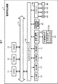
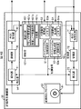
図2は、本発明を適用した記録再生装置1の一実施の形態の構成を示す図である。
FIG. 2 is a diagram showing a configuration of an embodiment of a recording / reproducing
CPU(Central Processing Unit)11は、ROM(Read Only Memory)12、または記憶部18に記憶されているプログラムに従って各種の処理を実行する。RAM(Random Access Memory)13には、CPU11が実行するプログラムやデータなどが適宜記憶される。これらのCPU11、ROM12、およびRAM13は、バス14により相互に接続されている。
A CPU (Central Processing Unit) 11 executes various processes according to a program stored in a ROM (Read Only Memory) 12 or a
CPU11には、バス14を介して入出力インタフェース15が接続されている。入出力インタフェース15には、キーボード、マウス、マイクロホンなどよりなる入力部16、ディスプレイ、スピーカなどよりなる出力部17が接続されている。CPU11は、入力部16から入力される指令に対応して各種の処理を実行する。そして、CPU11は、処理の結果得られた画像や音声等を出力部17に出力する。
An input /
入出力インタフェース15に接続されている記憶部18は、例えばハードディスクなどで構成され、CPU11が実行するプログラムや各種のデータを記憶する。通信部19は、外部のサーバなどの情報処理装置とインターネットやイントラネットなどに代表されるネットワークを介して通信する。
The
また、記憶部18は、各種のプログラムを記憶しており、CPU11は、これらのプログラムを読み出して対応する処理を実行する。記憶部18は、例えば、基本プログラムであるOSや、ドライバを記憶している。記憶部18に記憶されるプログラムは、上述のほかにも、通信部19を介してプログラムを取得して記憶するようにしてもよい。
The
画像・音声コーデック20は、ドライブ30に接続された磁気ディスク41、光ディスク42、光磁気ディスク43、或いは半導体メモリ44や、さらには、記録再生機構部22の記録媒体81(図3)より読み出された、所定の圧縮方式で圧縮されている画像や音声のファイルを所定の伸張して外部接続I/F(Interface)21や、出力部17に供給する。また、画像・音声コーデック20は、入力部16や外部接続I/F21より供給される画像信号や音声信号を所定の方式で圧縮し、ドライブ30に接続された磁気ディスク41、光ディスク42、光磁気ディスク43、或いは半導体メモリ44や、さらには、記録再生機構部22の記録媒体81(図3)に記録させる。
The image /
記録再生機構部22は、光磁気記録媒体である、例えば、Blu-Ray Disc(商標)などの記録媒体81(図3)に所定の情報を記録させたり、または、記録媒体81に記録された情報を読み出す。尚、記録再生機構部22の詳細な構成については、図3を参照して後述する。
The recording / reproducing
入出力インタフェース15に接続されているドライブ30は、磁気ディスク41、光ディスク42、光磁気ディスク43、或いは半導体メモリ44などが装着されたとき、それらを駆動し、そこに記録されているプログラムやデータなどを取得する。取得されたプログラムやデータは、必要に応じて記憶部18に転送され、記憶される。
The
次に、図2の記録再生装置1の動作について説明する。
Next, the operation of the recording / reproducing
CPU11は、入力部16より、外部接続I/F21を介して供給された入力データの記録が指示されると、ROM12、RAM13、または、記憶部18に記憶されているプログラムに基づいて、画像音声コーデック20を制御して、所定の圧縮方法で入力データを圧縮させて、記録再生機構部22に供給し、後述する記録媒体81(図3)に入力データを記録させる。
When the
また、入力部16より、記録再生機構部22に装着された記録媒体81に記録されたデータの再生が指示されると、ROM12、RAM13、または、記憶部18に記憶されているプログラムに基づいて、記録再生機構部22を制御して、記録媒体81に記録されたデータを再生させ、画像音声コーデック20に供給させると共に、画像音声コーデック20を制御して、所定の伸張方法で入力データを伸張させて、外部接続I/F21を介して外部に出力する、または、出力部17に出力させ、表示させる、若しくは、音声を出力させる。
Further, when the
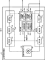
次に、図3を参照して、記録再生機構部22の詳細な構成について説明する。
Next, the detailed configuration of the recording / reproducing
制御部51は、記録再生機構部22の動作の全体を制御しており、CPU11より供給されてくる制御信号に基づいて、記録部52を制御して、記録再生ブロック53に記録媒体81に対して情報を記録させたり、または、再生部54を制御して、記録再生ブロック53に記録媒体81に記録されている情報を読み出させたりする。
The
制御部51のファイルシステム情報生成部62は、入力データのファイルの属性に基づいて、入力データのうちの所定の属性のファイルごとにグループ化して記録媒体81上の記録位置を決定し、ファイルを記録すると共に、それらの情報に基づいて、ファイルシステム情報を生成し、記録部52に供給し、記録媒体81に記録させる。この際、ファイルシステム情報生成部62は、記録媒体81上のUser領域、または、SA(SA:Spare Area)領域のいずれかにファイルシステム情報、アンカ情報、および、ボリューム構造の情報を記録させる。また、ファイルシステム情報生成部62の初期化部62aは、記録媒体81をフォーマットする際、記録領域を設定すると共に、代替セクタ領域とTDMA(Temporary Defect Management Area)領域を含むSA領域(ディスク管理領域)を設定する。代替セクタは、物理的に記録媒体81上のセクタが破壊された場合、その破壊されているセクタの代わりに情報を記録するセクタである。この際、物理的な記録媒体81上の記録アドレスは変更されるものの、代替セクタが用いられても、論理アドレスは、変更されることがないため、論理アドレスを利用した情報の記録、または、読み出しにおいては、代替セクタを用いた場合でもその動作には影響しない。そこで制御部51のファイルシステム情報生成部62は、ファイルが追記、または、更新された場合、書込部73を制御して、ファイルシステム情報、アンカ情報およびボリューム構造の情報をSA領域(代替セクタ領域)に記録させる。TDMA領域は、データ書換や欠陥の検出に応じた代替処理が発生することに応じて、代替管理情報が追加記録される領域である。尚、以降の図45までの説明においては、TDMA領域と代替セクタ領域とを併せて、単にSA領域または代替セクタ領域と称する。TDMA領域を含めた詳細な説明は、図46以降において後述するものとする。
The file system
制御部51のファイルシステム情報認識部61は、再生部54より供給されるメインまたはミラーのいずれかのファイルシステム情報を読み出し、このファイルシステム情報に基づいて、所定のファイルを読み出す。より詳細には、ファイルシステム情報認識部61は、読出部91を制御してUser領域、または、SA領域のいずれかに記録されたファイルシステム情報、ボリューム構造の情報、および、アンカ情報を読み出させる。尚、図3の記録再生機構部22においては、記録媒体81に情報を記録するに当たり、同一のファイルシステム情報をそれぞれメインファイルシステム情報、および、ミラーファイルシステム情報として記録させることにより、何らかの事情でいずれか一方のファイルシステム情報が破壊されても、他方が利用できる2重構造となっている。尚、以降においては、メインファイルシステム情報をメインFSとも称するものとし、また、ミラーファイルシステム情報については、ミラーFSとも称するものとする。
The file system
代替情報管理部63は、書込処理が実行される際、書き込まれるデータが上書き処理であるような場合、クラスタ単位で論理的なアドレス上のデータの元の位置(代替元の位置)と、上書きされるデータが記録される論理的なアドレス上の位置(代替先の位置)とを対応付けて、DL(Defect List)としてメモリ63aに記憶させる。
When the write process is executed, the replacement
代替情報生成部64は、データを記録媒体81に記録させる際、代替情報管理部63のメモリ63aに記録されているDLを読み出し、クラスタ単位の代替元と代替先の情報から、代替先のクラスタの位置が連続的に配置されているような場合、連続領域をDL上の1のリストとして更新し、データを連続的な領域に纏めて記録させる。また、代替情報生成部64は、データを記録媒体81に記録させる際、代替情報管理部63のメモリ63aに記録されているDLを読み出し、代替先が連続的に配置されていないような場合、DLの複数の代替先を1に纏めるように代替先の配置を変更して、連続領域を構成した後、その連続領域を1のリストとして更新し、データを連続的な領域に纏めて記録させる。
When recording the data on the
記録再生ブロック53は、書込部73、または、読出部91により制御され、記録媒体81に対して物理的に情報を記録、または、再生する。記録媒体81は、機械的、光学的、磁気的、または、磁気光学的に記録可能なもので、繰り返し書込みが可能なもの(例えば、BD-RW(Blu-Ray Disc-Rewritable)、DVD-RW(Digital Versatile Disc-Rewritable)、またはDVD-RAM(Digital Versatile Disc-Random Access Memory)を含む)であってもよいし、1回書込みのみが可能なもの(例えば、BD-R(Blu-Ray Disc-Recordable)、DVD-R(Digital Versatile Disc-Recordable)、または、DVD-ROM(Digital Versatile Disc-Read Only Memory)を含む)など、その形式は問わず、データを記録、または、再生できるディスク型の記録媒体であればよいものである。従って、記録再生ブロック53は、これらの記録媒体81に対応して記録再生できるものであればいずれであってもよい。
The recording / reproducing
ECC符号化部71は、入力に誤り訂正符号を付加し、符号化し、変調部72に出力する。変調部72は、ECC符号化部71から入力されたデータを変調し、書込部73に出力する。書込部73は、変調部72から入力されたデータを記録再生ブロック53に供給し、記録媒体81に書き込む処理を実行させる。
The
再生部54の読出部91は、記録媒体81に記録されている情報を読み出す。復調部92は、読出部91が記録媒体81から読み出したデータを復調し、ECC復号部93に供給する。ECC復号部93は、復調部92より供給されたデータを、通常のファイル(例えば、AV(Audio Visual)ストリームデータなど)とファイルシステム情報とに分離し、通常のファイルを出力データとして出力し、ファイルシステム情報を制御部51に出力する。
The
次に、図4を参照して、ファイルシステム情報生成部62によりグループ化して管理される入力データのファイルの管理構造について説明する。尚、記録媒体81は、基本的にUDF形式でファイルが記録される。従って、以降で示される管理構造に従って、各ファイルは、UDF形式で記録媒体81に記録される。
Next, a file management structure of input data managed by the file system
図4は、書き換え可能な記録媒体にAVストリームデータを記録する際に、各種のデーファイルを管理する場合の例について示したものであり、その管理構造は、Blu-Ray Disc Rewritable(商標)規格の管理構造に準拠したものである(管理構造は、Blu-Ray Disc Rewritable(商標)規格に準拠しているが、記録形式は、UDF形式である)。図4においては、図中上からコンテンツ管理レイヤ、プレイリストレイヤ、および、クリップレイヤの3個のレイヤが示されている。尚、この管理構造は、Blu-Ray Disc Recordable(商標)の管理構造にも対応している。 FIG. 4 shows an example of managing various data files when AV stream data is recorded on a rewritable recording medium. The management structure is the Blu-Ray Disc Rewritable (trademark) standard. (The management structure conforms to the Blu-Ray Disc Rewritable (trademark) standard, but the recording format is the UDF format). In FIG. 4, three layers of a content management layer, a playlist layer, and a clip layer are shown from the top in the figure. This management structure also corresponds to the management structure of Blu-Ray Disc Recordable (trademark).
ここで、コンテンツ管理レイヤには、プレイリスト管理テーブル111、および、サムネイル管理テーブル112が属している。また、プレイリストレイヤには、プレイリスト113−1乃至113−3が属している。さらに、クリップレイヤには、クリップ情報121−1乃至121−3が属している。尚、以下において、プレイリスト113−1乃至113−3、および、クリップ情報121−1乃至121−3をそれぞれ区別する必要がない場合、単に、プレイリスト113、および、クリップ情報121を称するものとして、その他の構成についても同様に称するものとする。 Here, the playlist management table 111 and the thumbnail management table 112 belong to the content management layer. Also, playlists 113-1 to 113-3 belong to the playlist layer. Furthermore, clip information 121-1 to 121-3 belongs to the clip layer. In the following description, when it is not necessary to distinguish the playlists 113-1 to 113-3 and the clip information 121-1 to 121-3, the playlist 113 and the clip information 121 are simply referred to. Other configurations are also referred to in the same manner.
AVストリーム131のファイルとクリップ情報121のファイル(AVストリームの属性情報をもつ)の2つをあわせたものは、特にクリップと称されるものである。AVストリーム131は、例えばMPEG-TS(Moving Picture Experts Group-Transport Stream)データであり、Video、Audio、または字幕等の情報を多重化した構造のファイルである。また、AVストリーム131は、再生時の制御を行うためのコマンド情報も多重化されている場合がある。図中においては、コマンド情報が多重化されている例が示されている。 A combination of the AV stream 131 file and the clip information 121 file (having AV stream attribute information) is particularly called a clip. The AV stream 131 is, for example, MPEG-TS (Moving Picture Experts Group-Transport Stream) data, and is a file having a structure in which information such as Video, Audio, or subtitles is multiplexed. In addition, the AV stream 131 may be multiplexed with command information for performing control during reproduction. In the figure, an example in which command information is multiplexed is shown.
プレイリストはクリップの特定の範囲を再生開始点と再生終了点を使って参照するプレイアイテムを複数持つ構造になっており、1つのプレイリストによって複数の再生シーケンスを連続して再生する機能を提供している。さらに、ユーザにプレイリストの一覧を提示するためのプレイリスト管理テーブル111、およびサムネイル表示機能に使用するサムネイル管理テーブル112と、それぞれに対応するサムネイルファイル141−1,141−2およびサムネイルファイル151−1,151−2が存在する。 A playlist has a structure that has multiple play items that refer to a specific range of a clip by using the playback start point and playback end point, and provides a function to continuously play multiple playback sequences with one playlist. is doing. Furthermore, a playlist management table 111 for presenting a list of playlists to the user, a thumbnail management table 112 used for the thumbnail display function, and thumbnail files 141-1 and 141-2 and thumbnail files 151- 1,151-2 exists.
1個のAVストリーム131と、それの付属情報のペアを1個のオブジェクトと考え、それをクリップと呼ぶ。AVストリームファイルはAVストリームファイルと呼ばれ、その付属情報は、クリップ情報121と呼ばれる。 A pair of one AV stream 131 and its attached information is considered as one object, which is called a clip. The AV stream file is called an AV stream file, and the attached information is called clip information 121.
一般に、コンピュータ等で用いるファイルは、バイト列として扱われるが、AVストリーム131のコンテンツは、時間軸上に展開され、プレイリスト113は、クリップ情報121の中のアクセスポイントを主にタイムスタンプで指定する。プレイリスト113によって、クリップの中のアクセスポイントのタイムスタンプが与えられた時、クリップ情報121は、AVストリーム131の中でストリームのデコードを開始すべきアドレス情報(データバイト位置)を見つけるために用いられる。 In general, a file used in a computer or the like is handled as a byte string, but the content of the AV stream 131 is expanded on the time axis, and the playlist 113 designates an access point in the clip information 121 mainly by a time stamp. To do. When the playlist 113 gives the time stamp of the access point in the clip, the clip information 121 is used to find address information (data byte position) in the AV stream 131 at which to start decoding the stream. It is done.
プレイリスト113は、クリップの中からユーザが見たい再生区間を選択し、それを簡単に編集することができることを目的にして導入されたものである。1つのプレイリスト113は、クリップの中の再生区間の集まりである。あるクリップの中の1つの再生区間は、プレイアイテムと呼ばれ、それは、時間軸上のIN点とOUT点のペアで表される。それゆえ、プレイリストは、プレイアイテムの集まりである。 The playlist 113 is introduced for the purpose of allowing a user to select a playback section that the user wants to see from clips and easily edit it. One playlist 113 is a collection of playback sections in a clip. One playback section in a clip is called a play item, which is represented by a pair of IN point and OUT point on the time axis. Therefore, a playlist is a collection of play items.
図4において、ファイルは、使用・更新頻度、グループに属するファイルの最大合計サイズにあわせて次のようにグループ化される。プレイリスト管理テーブル111、サムネイル管理テーブル112、およびプレイリスト113はグループ1に、クリップ情報121はグループ2に、メニュー用サムネイルファイル141,142はグループ3に、マーク用サムネイルファイル151,152はグループ4に分類される。
In FIG. 4, files are grouped as follows according to the usage / update frequency and the maximum total size of files belonging to the group. The playlist management table 111, thumbnail management table 112, and playlist 113 are in
これらのグループ化されるファイルは、AVストリーム131を再生する際に、必要とされる管理データである。これらの管理データを抽出して1箇所で管理することにより、管理データを素早く読み出すことが可能となる。結果として、AVストリームデータを高速で再生することが可能となる。 These files to be grouped are management data required when the AV stream 131 is reproduced. By extracting these management data and managing them in one place, the management data can be read quickly. As a result, AV stream data can be played back at high speed.
尚、以上においては、AVストリーム131の管理データのファイルをグループ化する例について説明してきたが、Blu-ray Disc Rewritable規格では定義されていないファイルをグループ化することも可能である。すなわち、図中においては、AVストリーム131の管理データのファイルとは異なるファイルのグループとして、グループXが定義され、ファイル161−1,161−2がそのグループに属している。尚、図中のファイル171−1,171−2は、グループ化されないファイルであることが示されている。また、AVストリーム131は、管理データではないので、グループ化管理されていない。 In the above, the example of grouping the management data files of the AV stream 131 has been described. However, it is also possible to group files that are not defined in the Blu-ray Disc Rewritable standard. That is, in the figure, a group X is defined as a file group different from the management data file of the AV stream 131, and the files 161-1 and 161-2 belong to the group. Note that files 171-1 and 171-2 in the figure are files that are not grouped. Further, since the AV stream 131 is not management data, it is not managed as a group.
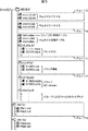
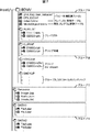
図5に、記録媒体81に記録されるBlu-Ray Disc Rewritable Format(BD-RE)で定義されるBlu-Ray Disc Audio Visual(BDAV)情報のディレクトリ構造の例を示す。尚、rootディレクトリの下に、これら以外のディレクトリを作っても良いが、それらは、UDF形式の記録では、無視される。また、図5のディレクトリ構造は、Blu-Ray Disc Recordable(BD-R)にも対応している。
FIG. 5 shows an example of the directory structure of Blu-Ray Disc Audio Visual (BDAV) information defined in Blu-Ray Disc Rewritable Format (BD-RE) recorded on the
同図に示されるように、rootディレクトリは、1個のディレクトリを含む。 As shown in the figure, the root directory includes one directory.
"BDAV"ディレクトリには、BDAVアプリケーションフォーマットによって規定されるすべてのファイルとディレクトリが記録される。また、"BDAV"ディレクトリは、以下に説明するディレクトリを含む。 In the “BDAV” directory, all files and directories defined by the BDAV application format are recorded. Further, the “BDAV” directory includes directories described below.
"PLAYLIST"ディレクトリには、プレイリスト113のデータベースファイルが記録される。また、このディレクトリは、プレイリスト113が、仮に1個も存在しないような場合にでも設定される。 A database file of the playlist 113 is recorded in the “PLAYLIST” directory. This directory is set even when there is no playlist 113.
"CLIPINF"ディレクトリには、クリップのデータベースが記録される。このディレクトリは、クリップが、仮に1個も存在しないような場合にでも設定される。 A database of clips is recorded in the “CLIPINF” directory. This directory is set even when there is no clip.
"STREAM"ディレクトリには、AVストリームファイルが記録される。このディレクトリは、AVストリームファイルが、仮に1個も存在しないような場合にでも設定される。 An AV stream file is recorded in the “STREAM” directory. This directory is set even when there is no AV stream file.
"BACKUP"ディレクトリには、グループ1,2に分類されるファイルのバックアップファイルが記録される。このディレクトリは、グループ1,2に分類されるファイルが、仮に1個も存在しないような場合にでも設定される。
In the “BACKUP” directory, backup files of files classified into
"PLAYLIST"ディレクトリは、Real PlayListとVirtual PlayListの2種類のPlayListファイルを記録している。図5の場合、11111.rpls,22222.vplsが、記録されている。このうち"xxxxx.rpls"で示されるファイルは、1個のReal PlayListに関連する情報を保持しており、プレイリスト毎に、1個のファイルが作られる。ここで、"xxxxx"は、5個の0から9まで数字である。 The “PLAYLIST” directory records two types of PlayList files, Real PlayList and Virtual PlayList. In the case of FIG. 5, 11111.rpls and 22222.vpls are recorded. Of these, the file indicated by “xxxxx.rpls” holds information related to one Real PlayList, and one file is created for each playlist. Here, “xxxxx” is five numbers from 0 to 9.
"yyyyy.vpls"で示されるファイルは、1個のVirtual PlayListに関連する情報を保持しており、プレイリスト毎に、1個のファイルが作られる。ファイル名は、"yyyyy.vpls"である。ここで、"yyyyy"は、5個の0から9まで数字である。 The file indicated by “yyyyy.vpls” holds information related to one Virtual PlayList, and one file is created for each playlist. The file name is “yyyyy.vpls”. Here, “yyyyy” is five numbers from 0 to 9.
Real PlayListは、それが参照しているクリップのストリーム部分を共有しているとみなされる。すなわち、Real PlayListは、それが参照しているクリップのAVストリーム部分に相当するデータ容量をディスクの中で占める。AVストリームが新しいクリップとして記録される場合、そのクリップ全体の再生可能範囲を参照するReal PlayListが生成される。Real PlayListの再生範囲の一部分が消去された場合、それが参照しているClipのストリーム部分のデータもまた消去される。 A Real PlayList is considered to share the stream portion of the clip it references. That is, the Real PlayList occupies the data capacity corresponding to the AV stream portion of the clip referenced by the Real PlayList in the disc. When the AV stream is recorded as a new clip, a Real PlayList that refers to the reproducible range of the entire clip is generated. When a part of the playback range of the Real PlayList is erased, the data of the clip stream part to which it refers is also erased.
Virtual PlayListは、クリップのデータを共有していないとみなされる。VirtualPlayListが変更または消去されたとしても、クリップは何も変化しない。尚、本明細書の説明においては、Real PlayListとVirtual PlayListを総称して単に、プレイリストと称するものとする。 The Virtual PlayList is regarded as not sharing the clip data. Even if the VirtualPlayList is changed or deleted, the clip does not change anything. In the description of the present specification, the Real PlayList and the Virtual PlayList are collectively referred to simply as a play list.
"CLIPINF"ディレクトリは、それぞれのAVストリームファイルに対応して、1個のファイルを保持している。図5の場合、01000.clpi,02000.clpiが保持されている。 The “CLIPINF” directory holds one file corresponding to each AV stream file. In the case of FIG. 5, 01000.clpi and 02000.clpi are held.
"zzzzz.clpi"で示されるファイルは、1個のAVストリーム131に対応するクリップ情報121である。ファイル名は、"zzzzz.clpi"であり、ここで、"zzzzz"は、5個の0から9までの数字である。 A file indicated by “zzzzz.clpi” is clip information 121 corresponding to one AV stream 131. The file name is “zzzzz.clpi”, where “zzzzz” is five numbers from 0 to 9.
"STREAM"ディレクトリは、AVストリームのファイルを保持する。図5の場合、01000.m2ts,02000.m2tsが保持されている。 The “STREAM” directory holds AV stream files. In the case of FIG. 5, 01000.m2ts and 02000.m2ts are held.
"zzzzz.m2ts"で示されるファイルは、AVストリーム131のファイルである。ファイル名は、"zzzzz.m2ts"であり、ここで"zzzzz"は、5個の0から9までの数字である。尚、1個のAVストリーム131のファイルとそれに対応するクリップ情報121は、同じ5個の数字"zzzzz"がファイル名として設定される。 The file indicated by “zzzzz.m2ts” is the AV stream 131 file. The file name is “zzzzz.m2ts”, where “zzzzz” is five numbers from 0 to 9. Note that the same five numbers “zzzzz” are set as file names in one AV stream 131 file and the corresponding clip information 121.
また、"BDAV"ディレクトリには、直下にサムネイルファイル141−1,141−2に対応するmenu1.tdt,menu2.tdtが保持されており、また、サムネイルファイル151−1,151−2に対応するmark1.tdt,mark2.tdtが保持されている。さらに、プレイリスト管理テーブル111に対応するinfo.bdav、サムネイル管理テーブル112に対応するmenu.tidx,mark.tidxが保持されている。 The “BDAV” directory holds menu1.tdt and menu2.tdt corresponding to the thumbnail files 141-1 and 141-2 immediately below, and also corresponds to the thumbnail files 151-1 and 151-2. mark1.tdt and mark2.tdt are held. Furthermore, info.bdav corresponding to the playlist management table 111 and menu.tidx and mark.tidx corresponding to the thumbnail management table 112 are held.
また、"root"ディレクトリ直下には、"DATA1"ディレクトリ、および、"DATA2"ディレクトリが設定されており、それぞれグループ管理されるファイルとして、ファイル161−1,161−2に対応するFile1.dat,File2.dat・・・、および、ファイル171−1,171−2に対応するFileA.dat,FileB.dat・・・が保持されている。 In addition, a “DATA1” directory and a “DATA2” directory are set immediately under the “root” directory, and File1.dat, corresponding to the files 161-1 and 161-2 are respectively managed as groups. File2.dat... And FileA.dat, FileB.dat... Corresponding to the files 171-1 and 171-2 are held.
図5で示されるディレクトリ下で管理されるファイルおよびディレクトリにおいて、図4で示されるように、サムネイルファイル141−1,141−2に対応するmenu1.tdt,menu2.tdtはグループ3として、サムネイルファイル151−1,151−2に対応するmark1.tdt,mark2.tdtは、グループ4として、プレイリスト管理テーブル111に対応するinfo.bdav、サムネイル管理テーブル112に対応するmenu.tidx,mark.tidx、並びに、"PLAYLIST"ディレクトリに保持されている11111.rpls,22222.vplsは、グループ1として、そして、"CLIPINF"ディレクトリに保持されている01000.clpi,02000.clpiは、グループ2としてそれぞれグループ化されて保持されている。
In the files and directories managed under the directory shown in FIG. 5, as shown in FIG. 4, menu1.tdt and menu2.tdt corresponding to the thumbnail files 141-1 and 141-2 are
さらに、上記のBDFSによりグループ管理されるファイル以外に、"DATA1"ディレクトリに保持されているファイル161−1,161−2に対応するFile1.dat,File2.datは、グループXとしてグループ化されている。 In addition to the files managed by the BDFS group, File1.dat and File2.dat corresponding to the files 161-1 and 161-2 held in the “DATA1” directory are grouped as a group X. Yes.
図4,図5においては、Blu-Ray Disc Rewritable(書き換え可能な記録媒体)の規格に基づいて、UDF形式で記録媒体81に記録される場合のグループ化における管理構造を示したが、次に、図6,図7を参照して、Blu-Ray Disc ROM(読み出し専用の記録媒体)におけるグループ化の管理構造(論理フォーマット)の例を示す。図5においては、HD(High Density)ムービーコンテンツを記録した場合の例について示している。
4 and 5 show the management structure in grouping in the case of recording on the
尚、図6において、プレイリスト221−1乃至221−3、クリップ情報231−1乃至231−3、AVストリーム232−1乃至232−3、ファイル251−1,251−2、および、ファイル261−1,261−2は、図4におけるプレイリスト113−1乃至113−3、クリップ情報121−1乃至121−3、AVストリーム131−1乃至131−3、ファイル161−1,161−2、および、ファイル171−1,171−2と同様のものであるので、その説明は適宜省略する。 In FIG. 6, playlists 221-1 to 221-3, clip information 231-1 to 231-3, AV streams 232-1 to 232-3, files 251-1 and 251-2, and file 261- 1, 261-2 are playlists 113-1 to 113-3, clip information 121-1 to 121-3, AV streams 131-1 to 131-3, files 161-1 and 161-2 in FIG. The file 171-1 and 171-2 are the same as the file 171-1 and 171-2, and the description thereof is omitted as appropriate.
図4で説明したクリップ情報231、および、プレイリスト221の上位に、再生プログラム211−1,211−2(ムービーオブジェクト)、および、タイトル201,202の2つのレイヤが存在する。再生プログラム211(ムービーオブジェクト)は再生するプレイリストの指定のほか、ユーザの操作に対する応答、タイトル201または202間のジャンプ、再生シーケンスの分岐など、HDムービーコンテンツの提示に必要な機能をプログラマブルに提供している。
Two layers of playback programs 211-1 and 211-2 (movie objects) and
タイトル201,202はユーザから認識でき、コンテンツの再生を開始するためのインデックスとして使用される。タイトル201,202は実行するムービーオブジェクトを1つ指定する構造になっている。また、通常のタイトルのほかに、最初に自動的に再生されるタイトル、メニューを表示するためのタイトルも存在しする。
The
また、アプリ(アプリケーションプログラム)203,204は、拡張アプリケーションであるゲームやWebコンテンツを実行させるものであり、その際、再生プログラム(実行Object)212−1,212−2を起動させ実行させる。再生プログラム212は、プレイリストを使用する場合とプレイリストを使用しない場合がある。また、再生プログラム212は、これらのアプリケーションプログラム203,204においては任意の画像ファイル241、音声ファイル242、ファイル243を参照することができる。
The applications (application programs) 203 and 204 are for executing games and Web contents that are extended applications. At this time, the reproduction programs (execution objects) 212-1 and 212-2 are activated and executed. The playback program 212 may use a playlist or may not use a playlist. Further, the reproduction program 212 can refer to any
HDムービーコンテンツを示すタイトル201,202、および、アプリケーション202,203は、さらにその数を増やすことも可能であり、図6においては、Other205として示されている。また、記録媒体81上で混在して記録することも可能であり、図6は混在した状態を示している。
The numbers of the
図6においても、図4で示した場合と同様に、ファイルは、使用・更新頻度、グループに属するファイルの最大合計サイズにあわせて次のようにグループ化される。すなわち、タイトル201,202、アプリ203,204、Other205、再生プログラム211−1,211−2,212−1,212−1、およびプレイリスト221−1乃至221−3は、はグループAに、クリップ情報231はグループBに、画像ファイル241、音声ファイル242、および、ファイル243はグループCに分類される。
In FIG. 6, as in the case shown in FIG. 4, files are grouped as follows according to the usage / update frequency and the maximum total size of files belonging to the group. That is,
尚、図6のグループA,B,Cは、図4のグループ1,2,3,4と同様に便宜的に分けて名称がついているだけであり、処理するファイルの1群という意味で同様のものである。
Note that the groups A, B, and C in FIG. 6 are simply named for convenience as in the case of the
図7に、記録媒体81に記録されるBlu-Ray Disc ROM Format(BD-ROM)で定義されるBlu-Ray Disc Movie(BDMV)情報のディレクトリ構造の例を示す。尚、rootディレクトリの下に、これら以外のディレクトリを作っても良いが、それらは、UDF形式の記録では、無視される。
FIG. 7 shows an example of the directory structure of Blu-Ray Disc Movie (BDMV) information defined in Blu-Ray Disc ROM Format (BD-ROM) recorded on the
同図に示されるように、rootディレクトリは、1個のディレクトリを含む。 As shown in the figure, the root directory includes one directory.
"BDMV"には、BDMVアプリケーションフォーマットによって規定されるすべてのファイルとディレクトリが記録される。また、"BDMV"ディレクトリは、以下に説明するディレクトリを含む。 In “BDMV”, all files and directories defined by the BDMV application format are recorded. Further, the “BDMV” directory includes directories described below.
"PLAYLIST"ディレクトリには、プレイリスト221のデータベースファイルが記録される。また、このディレクトリは、プレイリスト221が、仮に1個も存在しないような場合にでも設定される。 A database file of the playlist 221 is recorded in the “PLAYLIST” directory. This directory is set even when there is no playlist 221.
"CLIPINF"ディレクトリには、クリップのデータベースが記録される。このディレクトリは、クリップが、仮に1個も存在しないような場合にでも設定される。 A database of clips is recorded in the “CLIPINF” directory. This directory is set even when there is no clip.
"STREAM"ディレクトリには、AVストリームファイルが記録される。このディレクトリは、AVストリームファイルが、仮に1個も存在しないような場合にでも設定される。 An AV stream file is recorded in the “STREAM” directory. This directory is set even when there is no AV stream file.
"BACKUP"ディレクトリには、グループA,Bに分類されるファイルのバックアップファイルが記録される。このディレクトリは、グループA,Bに分類されるファイルが、仮に1個も存在しないような場合にでも設定される。 In the “BACKUP” directory, backup files of files classified into groups A and B are recorded. This directory is set even when there are no files classified into groups A and B.
"PLAYLIST"ディレクトリは、図7の場合、11111.rpls,22222.rplsが、記録されている。このうち"xxxxx.rpls"で示されるファイルは、1個のMovie PlayListに関連する情報を保持しており、プレイリスト毎に、1個のファイルが作られる。ここで、"xxxxx"は、5個の0から9まで数字である。 In the “PLAYLIST” directory in the case of FIG. 7, 11111.rpls and 22222.rpls are recorded. Of these, the file indicated by “xxxxx.rpls” holds information related to one Movie PlayList, and one file is created for each playlist. Here, “xxxxx” is five numbers from 0 to 9.
"CLIPINF"ディレクトリは、それぞれのAVストリームファイルに対応して、1個のファイルを保持している。図7の場合、01000.clpi,02000.clpiが保持されている。 The “CLIPINF” directory holds one file corresponding to each AV stream file. In the case of FIG. 7, 01000.clpi and 02000.clpi are held.
"zzzzz.clpi"で示されるファイルは、1個のAVストリーム232に対応するクリップ情報231である。ファイル名は、"zzzzz.clpi"であり、ここで、"zzzzz"は、5個の0から9までの数字である。
A file indicated by “zzzzz.clpi” is clip information 231 corresponding to one
"STREAM"ディレクトリは、AVストリームのファイルを保持する。図7の場合、01000.m2ts,02000.m2tsが保持されている。 The “STREAM” directory holds AV stream files. In the case of FIG. 7, 01000.m2ts and 02000.m2ts are held.
"zzzzz.m2ts"で示されるファイルは、AVストリーム232のファイルである。ファイル名は、"zzzzz.m2ts"であり、ここで"zzzzz"は、5個の0から9までの数字である。尚、1個のAVストリーム232のファイルとそれに対応するクリップ情報231は、同じ5個の数字"zzzzz"がファイル名として設定される。
The file indicated by “zzzzz.m2ts” is an
また、"BDMV"ディレクトリには、直下には、コピー制御関連ファイルとして、Unit_Key_Gen_Value.inf、および、CPS_CCI.infが保持されており、また、タイトル管理テーブルのファイルとしてindex.bdmvが保持されている。さらに、再生プログラム管理テーブルとしてMoviObject.bdmvが保持されている。 In the "BDMV" directory, Unit_Key_Gen_Value.inf and CPS_CCI.inf are held as copy control related files, and index.bdmv is held as a title management table file. . Furthermore, MoviObject.bdmv is held as a playback program management table.
また、"root"ディレクトリ直下には、"Resource"ディレクトリ、"DATA1"ディレクトリ、および、"DATA2"ディレクトリが設定されている。これらのディレクトリはBlu-Ray Disc ROM Format において必須のディレクトリではないが、コンテンツの内容によって必要となる拡張データを格納するためのディレクトリの例として追加したものである。"Resource"ディレクトリには、グループ管理されるファイルである、画像ファイル241、音声ファイル242、および、ファイル243に対応するImage.jpg,Audio.pcm、および、Jimaku.txtが保持されている。また、"DATA1"ディレクトリには、ファイル251−1,251−2に対応するFile1.dat,File2.datが保持されており、さらに、"DATA2"ディレクトリには、ファイル261−1,261−2に対応するFileA.dat,FileB.dat・・・が保持されている。
In addition, immediately under the “root” directory, a “Resource” directory, a “DATA1” directory, and a “DATA2” directory are set. These directories are not essential directories in the Blu-Ray Disc ROM Format, but are added as examples of directories for storing extended data required by the contents. In the “Resource” directory, Image.jpg, Audio.pcm, and Jimaku.txt corresponding to the
図7で示されるディレクトリ下で管理されるファイルおよびディレクトリにおいては、Unit_Key_Gen_Value.inf、CPS_CCI.inf、index.bdmvおよび、MoviObject.bdmv、並びに、"PLAYLIST"ディレクトリに保持されている11111.mpls,22222.mplsは、グループAとして、"CLIPINF"ディレクトリに保持されている01000.clpi,02000.clpiは、グループBとして、そして、"Resource"ディレクトリに保持されているImage.jpg,Audio.pcm、および、Jimaku.txtは、グループCとしてそれぞれグループ化されて保持されている。 In the files and directories managed under the directory shown in FIG. 7, Unit_Key_Gen_Value.inf, CPS_CCI.inf, index.bdmv, MoviObject.bdmv, and 11111.mpls, 22222 held in the “PLAYLIST” directory .mpls is group A, 01000.clpi held in the "CLIPINF" directory, 02000.clpi is group B, and Image.jpg, Audio.pcm, held in the "Resource" directory, and , Jimaku.txt is stored as a group C.
さらに、上記のグループ管理されるファイル以外に、"DATA1"ディレクトリに保持されているファイル251−1,251−2に対応するFile1.dat,File2.datは、グループXとしてグループ化されている。 In addition to the files managed in the above group, File1.dat and File2.dat corresponding to the files 251-1 and 251-2 held in the “DATA1” directory are grouped as a group X.
次に、本発明による記録処理の説明の前に、図8,図9を参照して、従来のUDFにおけるファイルへのアクセス手順について説明する。 Next, before describing the recording process according to the present invention, a file access procedure in a conventional UDF will be described with reference to FIGS.
図8は、UDFのVolume Structure構造の例を示しており、図9は、File Structure and Filesの内容を示したものである。ここでは、図9で示される”root/BDMV/Unit_Key_Gen_Value.inf“へアクセスする場合を例に説明する。 FIG. 8 shows an example of the UDF Volume Structure structure, and FIG. 9 shows the contents of File Structure and Files. Here, a case of accessing “root / BDMV / Unit_Key_Gen_Value.inf” shown in FIG. 9 will be described as an example.
図8において、Volume Structureは論理Volumeに関する情報やパーティション内部に記録されているFile Structureの解析開始点に関する情報を記録したものである。尚、図8において、最左列がLSN(論理セクタ番号(Logical Sector Number)を、左から2列目が、Structureを、右から2列目がDescriptorsを、そして、最右列がLBN(論理ブロック番号(Logical Block Number))を示している。また、図9において、最左列がLBN(論理ブロック番号(Logical Block Number))を、中央の列が、Structureを、最右列がDescriptorsをそれぞれ示している。 In FIG. 8, Volume Structure records information about logical volumes and information about the start point of analysis of File Structure recorded in the partition. In FIG. 8, the leftmost column is LSN (Logical Sector Number), the second column from the left is Structure, the second column from the right is Descriptors, and the rightmost column is LBN (logical 9, the leftmost column is LBN (Logical Block Number), the center column is Structure, and the rightmost column is Descriptors. Each is shown.
ボリューム内のアドレス情報はLSN(論理セクタ番号)、パーティション内のアドレスはLBN(論理ブロック番号)で表記される。また、ボリューム内に複数のパーティションが存在する場合、Logical Volume Descriptor内部に複数のパーティション情報を記録することができる。 Address information in the volume is represented by LSN (logical sector number), and addresses in the partition are represented by LBN (logical block number). Further, when there are a plurality of partitions in the volume, a plurality of pieces of partition information can be recorded in the Logical Volume Descriptor.
尚、図8,図9については、処理に必要な項目のみを説明し、処理に不要な項目については、適宜説明を省略する。 8 and 9, only the items necessary for the process will be described, and description of the items unnecessary for the process will be omitted as appropriate.
まず、図8の番号1で示されるLSNが256の位置であるAnchor-1のアンカ情報(Anchor Volume Descriptor Pointer)を解析し、番号2で示されるVolume Descriptor Sequenceの位置を取得する。続いて、番号2で示されるLSNが32乃至47の位置となるVolume Descriptor Sequenceを解析する。Volume Descriptor Sequenceには、”Primary Volume Descriptor”、”Implementation Use Volume Descriptor”、”Partition Descriptor”、”Logical Volume Descriptor”、”Unallocated Spece Descriptor”、”Terminating Descriptor”、および、”Trailing Logical Sectors”が含まれており、それぞれ、”Primary Volume Descriptor”はボリュームを識別する情報を、”Implementation Use Volume Descriptor”は互換性を示す情報を、”Partition Descriptor”はパーティションを識別する情報を、”Logical Volume Descriptor”は論理パーティションの位置を示す情報を、”Unallocated Spece Descriptor”は未使用領域を示す情報、”Terminating Descriptor”は領域の最後の位置を示す情報を、そして、”Trailing Logical Sectors”は残りの領域の情報を格納している。
First, the anchor information (Anchor Volume Descriptor Pointer) of Anchor-1 where the LSN indicated by the
このうち、図8の番号3で示されているLSNが35の”Logical Volume Descriptor”に記載された”Logical Volume Integrity Sequence”の位置と、目的のパーティションの位置、パーティション内部のFile Set Descriptorの位置を取得する。
Among these, the position of the “Logical Volume Integrity Sequence” described in the “Logical Volume Descriptor” with the LSN of 35 indicated by the
さらに、番号4で示されるLSNが48の”Logical Volume Integrity Sequence”を解析し、Volume情報の整合性チェックを行い、整合性に問題が無ければ、番号5で示されるLSN272乃至272Nall−272のFile Structure and Filesのパーティション内部を解析する。以上の手順で目的のパーティションへのアクセスを開始できる。
Further, the “Logical Volume Integrity Sequence” with 48 LSN indicated by the
続いて、図9の番号11で示されるLBNが(A+1)のFile Set Descriptorには、rootの情報が格納されているので、これを解析し、番号12で示されるLBNが(A+3)のルートディレクトリのFile Entry(図中では、FE(Root Directory)と示されている)の位置を取得する。
Subsequently, since the root information is stored in the File Set Descriptor with the LBN of (A + 1) indicated by the
さらに、番号12で示されるLBNが(A+3)のルートディレクトリのFile Entry(図中では、FE(Root Directory)と示されている)を解析し、ルートディレクトリの情報が記載された位置(LBN=A+4)を取得する。次に、ルートディレクトリの情報の中にある番号13で示されるBDMVディレクトリのFID(File Identifier Descriptor)を解析して、番号14で示されるBDMVディレクトリのFE(File Entry)(図中では、FE(BDMV)と示されている)の位置(LBN=A+5)を取得する。
Further, the File Entry (indicated as FE (Root Directory) in the figure) of the root directory whose LBN indicated by the
さらに、番号14で示されるBDMVディレクトリのFile Entryを解析し、BDMVディレクトリの情報が記録されている位置(LBN=A+9)を取得する。
Further, the File Entry of the BDMV directory indicated by the
続いて、BDMVディレクトリの情報を取得し、番号15で示されるBDMVディレクトリにあるUnit_Key_Gen_Value.inf のFile Identifier Descriptorを解析してUnit_Key_Gen_Value.inf のFile Entryの位置を取得する。そして、番号16のUnit_Key_Gen_Value.infのFile Entryを解析し、Unit_Key_Gen_Value.infのデータが記録されている位置を取得し、Unit_Key_Gen_Value.infのデータが記録されたアドレスへアクセスし、目的のデータを取得する。以上の手順で”番号17で示されるroot/BDMV/Unit_Key_Gen_Value.inf“ファイルのデータを取得することができる。
Subsequently, information on the BDMV directory is acquired, and the File Identifier Descriptor of Unit_Key_Gen_Value.inf in the BDMV directory indicated by the
UDF2.50で導入されたメタデータパーティションが使用されている場合、番号11で示されるFile Set Descriptor、番号12で示されるルートディレクトリのFile Entry、番号13で示されるBDMVディレクトリのFID(File Identifier Descriptor)、番号14で示されるBDMVディレクトリのFE(File Entry)、番号15で示されるBDMVディレクトリにあるUnit_Key_Gen_Value.infのFile Identifier Descriptor、および番号16のUnit_Key_Gen_Value.infのFile Entryはメタデータパーティション内に論理アドレスを使用して配置される。
When the metadata partition introduced in UDF2.50 is used, the File Set Descriptor indicated by the
メタデータパーティションが記録されている位置は、メタデータファイルのファイルエントリによって取得できる。メタデータパーティション内のデータを一度にメモリに読み込むことにより、複数階層のディレクトリの下に保存されているファイルにアクセスする際も、ディレクトリを1段下るごとにFile Identifier Descriptor、File Entry、ディレクトリ情報の3の情報を個々に記録媒体上から読み出すことを避け、メモリ上に読み出されているメタデータパーティションの情報からファイルの読み出しに必要な情報を取得し解析することが可能である。 The position where the metadata partition is recorded can be acquired by the file entry of the metadata file. By reading the data in the metadata partition into memory at once, even when accessing files stored under multiple levels of directories, the file identifier descriptor, file entry, and directory information It is possible to avoid reading the information of 3 individually from the recording medium and to acquire and analyze information necessary for reading the file from the information of the metadata partition read on the memory.
次に、図10乃至図12を参照して、ファイルシステム情報を仮想アドレスに配置する手法について説明する。 Next, a method for arranging file system information at a virtual address will be described with reference to FIGS.
ファイルシステム情報は、ファイルシステムで用いる通常の物理パーティション上のアドレスを用いて、メタデータファイルとして1箇所に固めて配置される。メタデータファイル内は仮想アドレス(パーティションの先頭をアドレス0とする)が割り当てられ、ファイルシステム情報はメタデータパーティション内に、この仮想アドレスを参照する形式で構築される。
The file system information is arranged in one place as a metadata file using an address on a normal physical partition used in the file system. A virtual address (
すなわち、図9で説明したような番号11で示されるFile Set Descriptor、番号12で示されるルートディレクトリのFile Entry、番号13で示されるBDMVディレクトリのFID(File Identifier Descriptor)、番号14で示されるBDMVディレクトリのFE(File Entry)、番号15で示されるBDMVディレクトリにあるUnit_Key_Gen_Value.infのFile Identifier Descriptor、および番号16のUnit_Key_Gen_Value.infのFile Entry(ファイルエントリ)までの情報を、メタデータファイル内の仮想アドレスを用いて辿ること(読み出すこと)ができるようになっている。
That is, the File Set Descriptor indicated by the
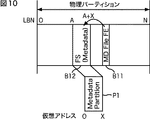
図10の上段においては、領域B11には、MD File FE(Metadata File File-Entry)が記述され、この記述に基づいて、領域B12に記録されているファイルシステム情報(FS)を辿ることができる。すなわち、領域B12のMD File FEには、物理パーティションにおけるアドレスA乃至A+Xの領域である領域B11にファイルシステム情報(FS)が記録されていることが示されている。また、図10の下段で示されるように、上述したファイルシステム情報(FS)は、メタデータパーティション内の仮想アドレス0乃至Xの領域P1に記述される。
In the upper part of FIG. 10, MD File FE (Metadata File File-Entry) is described in the area B11, and the file system information (FS) recorded in the area B12 can be traced based on this description. . That is, the MD File FE in the area B12 indicates that file system information (FS) is recorded in the area B11 that is the area of addresses A to A + X in the physical partition. As shown in the lower part of FIG. 10, the file system information (FS) described above is described in the area P1 of
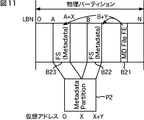
また、メタデータパーティションは、物理パーティションにおける複数の領域に配置してもよい。例えば、図11上段で示されるように、物理パーティションのアドレスA乃至A+Xの領域B23と物理パーティションのアドレスB乃至B+Yの2箇所に配置されていた場合、領域B21のMD File FEには、物理パーティションにおけるアドレスA乃至A+Xの領域である領域B23と物理パーティションのアドレスB乃至B+Yである領域B22の2箇所にファイルシステム情報が記録されていることが示される。そして、図11下段で示されるようにメタデータパーティション内の仮想アドレス0乃至X+Yの領域P2にファイルシステム情報が記録されることになる。
The metadata partition may be arranged in a plurality of areas in the physical partition. For example, as shown in the upper part of FIG. 11, when the physical partition addresses A to A + X are located in two areas B23 and physical partition addresses B to B + Y, the MD File FE in the area B21 is stored. Indicates that file system information is recorded at two locations, an area B23 which is an area of addresses A to A + X in the physical partition and an area B22 which is an address B to B + Y of the physical partition. Then, as shown in the lower part of FIG. 11, the file system information is recorded in the area P2 of
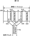
さらに、UDF2.50で採用されている機能としてメタデータファイルを二重に配置して(一方をメインメタデータファイル(=メインFS)、他方をミラーメタデータファイル(ミラーFS)と称する同一の2のメタデータファイル(FS)を配置して)ファイルシステム情報の信頼性を高めることも可能である。 Further, as a function adopted in UDF2.50, two metadata files are arranged (one is a main metadata file (= main FS) and the other is called a mirror metadata file (mirror FS). It is also possible to increase the reliability of file system information (by placing metadata files (FS)).
すなわち、図12で示されるように、物理パーティションのアドレスA乃至A+Xの領域B32にファイルシステム情報である(メイン)メタデータファイルが配置され、物理パーティションのアドレスB乃至B+Yの領域B34にファイルシステム情報であるミラーメタデータファイルが配置されていた場合、領域B31のMD File FEには、物理パーティションにおけるアドレスA乃至A+Xの領域である領域B32にメタデータファイルが記録されていることが示される。そして、図12下段で示されるようにメタデータパーティション内の仮想アドレス0乃至Xの領域P3に(メイン)メタデータファイルとしてファイルシステム情報が記録されることになる。このとき、同様にして、領域B33のMDM File FEには、物理パーティションにおけるアドレスB乃至B+Xの領域である領域B34にミラーメタデータファイルが記録されていることが示される。そして、上述のメインメタデータファイルと同様に、図12下段で示されるようにメタデータパーティション内の仮想アドレス0乃至Xの領域P3にミラーメタデータファイルとしてファイルシステム情報が記録されることになる。このように、同一のメタデータファイルを記述することにより、ファイルシステム情報の信頼性を向上させることが可能となる。
That is, as shown in FIG. 12, the (main) metadata file as file system information is arranged in the area B32 of addresses A to A + X of the physical partition, and the area B34 of addresses B to B + Y of the physical partition. When a mirror metadata file that is file system information is arranged in the area B31, the metadata file is recorded in the area B32 that is the area of addresses A to A + X in the physical partition in the MD File FE of the area B31. It is shown. Then, as shown in the lower part of FIG. 12, file system information is recorded as a (main) metadata file in the area P3 of
次に、図13を参照して、記録媒体81がBD-Rである場合の記録方式について説明する。BD-Rの記録方式には、シーケンシャル記録モードとランダム記録モードが存在する。
Next, a recording method when the
シーケンシャル記録モードは、記録媒体の記録開始位置(一般に、ディスク状記録媒体の場合、ディスク中心部)から所定の方向に情報を順次記録していくモードである。一方、ランダム記録モードは、記録媒体上の位置をランダムに設定して情報を記録するモードである。ディスク状記録媒体においては、シーケンシャル記録方式で記録された情報の方が、時間的に前後の関係が反映された状態で情報が記録されるため、読み出し速度を高速にすることが可能となる。そこで、以降においては、シーケンシャル記録モードにおいて、情報が記録されるものとして説明を進めるものとする。但し、本発明の実施の形態としては、記録媒体に対して情報が記録されるモードは、シーケンシャル記録モードに限定されるわけではなく、ランダム記録モードであってもよい。 The sequential recording mode is a mode in which information is sequentially recorded in a predetermined direction from a recording start position of the recording medium (generally, in the case of a disk-shaped recording medium, the center of the disk). On the other hand, the random recording mode is a mode for recording information by randomly setting positions on the recording medium. In a disc-shaped recording medium, information recorded by the sequential recording method is recorded in a state in which the temporal relationship is reflected in time, so that the reading speed can be increased. Therefore, in the following description, it is assumed that information is recorded in the sequential recording mode. However, as an embodiment of the present invention, the mode in which information is recorded on the recording medium is not limited to the sequential recording mode, and may be a random recording mode.
図13は、BD-Rの記録方式のうちシーケンシャル記録モードの概要を示した図である。 FIG. 13 is a diagram showing an outline of the sequential recording mode among the BD-R recording methods.
BD-Rに記録される情報は、User領域にセッション(Session)単位で記録される。図13においては、User領域にSession1,2と示された2のセッションが記述されているが、それ以上のセッションであっても良いことは言うまでもない。セッションは、1以上のSRR(Sequential Recording Ranges)から構成される。また、マルチセッションを構成することもできるが、記録可能なセッションは、最後に設定されたセッションのみである。
Information recorded on the BD-R is recorded in the User area in units of sessions. In FIG. 13, two sessions indicated as
SRR(Sequential Recording Ranges)は、BD-Rに記録される情報の最小単位である複数のクラスタ(64KB)から構成されるものであり、CD-R(Compact Disc-Recordable)メディアにおけるトラックに相当する記録単位である。また、SRRは、OpenまたはClosedの2の状態があり、Openのとき記録可能であり、記録が終了した後、Closedにされると記録不能な状態となる。さらに、セッションは、最大16個までOpenの状態とすることができる。また、SRRは、1のBD-Rに最大約7600個設定することができる。図13においては、SRR#1乃至#5が設定されており、SRR#1乃至#4には、領域281−1乃至281−4に既に情報が記録されていることが示されている(recodedと示されている)。また、領域281−1乃至281−4の終端部には、LRA(Last Recoding Allocation)と記述されており、最終記録位置であることが示されている。また、図13においては、セッション#3,#5は、Openの状態であり、それ以外のセッションは、Closedの上である。このため、セッション#3,#5においては、LRAの直後の位置が、新たに記録を開始するNWA(New Writing Allocation)であることが示されている。
SRR (Sequential Recording Ranges) is composed of a plurality of clusters (64 KB), which is the smallest unit of information recorded on a BD-R, and corresponds to a track on a CD-R (Compact Disc-Recordable) medium. A recording unit. The SRR has two states, Open and Closed, and can be recorded when Open. When the recording is completed and then Closed, the SRR becomes unrecordable. Furthermore, up to 16 sessions can be open. Also, a maximum of about 7600 SRRs can be set for one BD-R. In FIG. 13,
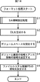
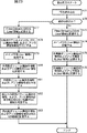
次に、図14のフローチャートを参照して、記録媒体81のフォーマット処理について説明する。
Next, the format processing of the
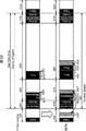
ステップS1において、制御部51のファイルシステム情報生成部62の初期化部62aは、書込部73を制御して、記録再生ブロック53に対して記録媒体81上にSA(Spare Area)領域を設定させるSA領域設定処理を実行させる。すなわち、例えば、記録媒体81が1層式のBD-Rである場合、図15で示されるように、Disc内周側と外周側のそれぞれの記録領域の端部にSA領域が設定される。
In step S1, the
ここで、図15においては、図中左方向が記録媒体81の内周側を示し、図中右方向が記録媒体81の外周側を示す。また、記録媒体81への記録は、内周側から外周側に向かってなされる。また、記録媒体81には、内周側端部に記録に寄与しない導入部(Lead in Zone)(情報が記録されない領域)と外周側端部に記録に寄与しない導出部(Lead out Zone)(情報が記録されない領域)がそれぞれ設けられている。
Here, in FIG. 15, the left direction in the figure indicates the inner peripheral side of the
この場合、初期化部62aは、導入部と導出部とのそれぞれの隣接領域に、内周側のSA領域(ISA)と外周側のSA領域(OSA)をそれぞれ設定させる。この結果、ISAとOSAの間の領域が、User領域(User Data Area)となり、実質的にこのUser領域に各種の情報が記録されることになる。User領域内においては、上述したように内周側から外周側に向かって情報が記録されることになるため、LSN(論理セクタ番号)は、図中の矢印で示されるように内周側から外周側に向かって設定される。
In this case, the
尚、このISAおよびOSAのそれぞれの領域の大きさは、任意に設定することが可能であるが、ISAおよびOSAの領域を大きく設定することにより、クラスタの破壊や、後述する情報の書き込み処理を安定したものとすることができるが、その分、User領域が小さくなるため、情報を記録するために有効となる領域が小さくなる。 Note that the size of the ISA and OSA areas can be set arbitrarily, but by setting the ISA and OSA areas large, cluster destruction and information write processing (to be described later) can be performed. Although the user area can be stabilized, the user area becomes smaller by that amount, and the area effective for recording information becomes smaller.
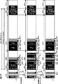
また、例えば、記録媒体81が2層式のBD-Rである場合、図16で示されるように、1層面と2層面のそれぞれのDisc内周側と外周側のそれぞれの記録領域の端部にSA領域が設定される。
Also, for example, when the
ここで、図16においては、図中左方向が記録媒体81の内周側を示し、図中右方向が記録媒体81の外周側を示す。また、図16中の上段のL0で示される層が、1層面の構成を示し、図16中の下段のL1で示される層が2層面の構成を示している。
Here, in FIG. 16, the left direction in the figure indicates the inner peripheral side of the
また、2層式BD-Rの場合、記録媒体81への記録は、1層面において、内周側から外周側に向かってなされ、2層面においては、外周側から内周側に向かってなされる。さらに、記録媒体81には、1層面に内周側端部に記録に寄与しない導入部(Lead in Zone0)(情報が記録されない領域)と外周側端部に記録に寄与しない導出部(Lead out Zone0)(情報が記録されない領域)がそれぞれ設けられ、2層面に内周側端部に記録に寄与しない導入部(Lead in Zone1)(情報が記録されない領域)と外周側端部に記録に寄与しない導出部(Lead out Zone1)(情報が記録されない領域)がそれぞれ設けられている。
In the case of the two-layer BD-R, recording on the
この場合、初期化部62aは、1層面と2層面の導入部と導出部とのそれぞれの隣接領域に、内周側のSA領域(ISA0,1)と外周側のSA領域(OSA0,1)をそれぞれ設定させる。この結果、1層面のISA0とOSA0、および、2層面のISA1とOSA1の間の領域が、User領域となり、実質的にこのUser領域に各種の情報が記録されることになる。1層面のUser領域内においては、上述したように内周側から外周側に向かって情報が記録されることになるため、LSN(論理セクタ番号)は、内周側から外周側に向かって設定される。一方、2層面のUser領域内においては、上述したように外周側から内周側に向かって情報が記録されることになるため、LSN(論理セクタ番号)も、外周側から内周側に向かって設定される。尚、TDMA領域の設定を含むSA領域設定処理の詳細な説明については、図46を参照して詳細を後述する。
In this case, the
ここで、図14のフローチャートの説明に戻る。 Now, the description returns to the flowchart of FIG.
ステップS2において、初期化部62aは、代替情報管理部63に対して、DL(Defect List)を生成させる。これにより、代替情報管理部63は、メモリ63aにDLを生成し記憶させる。尚、この段階では、DLには情報が含まれていない。
In step S2, the
ステップS3において、初期化部62aは、書込部73を制御して、記録再生ブロック53に対して記録媒体81にボリュームスペースを設定させる。すなわち、例えば、後述する図18の上段で示されるように、ボリュームスペースを設定する。尚、図18においては、記録媒体81が1層式のBD-Rを用いた場合の例が示されている。
In step S3, the
ステップS4において、初期化部62aは、書込部73を制御して、記録再生ブロック53に対して記録媒体81にボリューム構造の情報とアンカ情報を記録するボリューム構造の情報を記録する領域とアンカ領域を設定させる。すなわち、後述する図18の上段で示される「Volume Str.」で示される領域と、「Anchor」で示される領域が設定される。尚、図18の例においては、ファイルシステム情報が2重に設定される構造となっているため、メインFSの領域に対応するボリューム構造の情報を記録する領域とアンカ領域(図中の領域B111に含まれる「Volume Str.」と「Anchor」の領域)と、ミラーFSの領域に対応するボリューム構造の情報を記録する領域とアンカ領域(図中の領域B113に含まれる「Volume Str.」と「Anchor」の領域)がそれぞれ設定される。
In step S4, the
ステップS5において、初期化部62aは、書込部73を制御して、記録再生ブロック53に対して記録媒体81にファイルシステム情報を記録するFS領域を設定させる。すなわち、後述する図18の上段で示される「FS」で示される領域を設定する。尚、図18の例においては、ファイルシステム情報が2重に設定される構造となっているため、メインFSの領域に対応するFS領域(図中の領域B111に含まれる「FS(Metadata)」の領域)と、ミラーFS領域(図中の領域B113に含まれる「FS(MD-Mirror)」の領域)がそれぞれ設定される。
In step S5, the
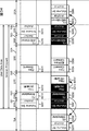
尚、図18においては、フォーマットに際して、図中左から、内周側のボリューム構造の情報およびアンカ情報、メインFS、ファイル(Files(Stream+DB))、ミラーFS、並びに、外周側のボリューム構造の情報およびアンカ情報が、それぞれ1のSRRに設定されている。 In FIG. 18, at the time of formatting, from the left in the figure, the volume structure information and anchor information on the inner circumference side, the main FS, the file (Files (Stream + DB)), the mirror FS, and the volume structure on the outer circumference side Information and anchor information are set in one SRR.
以上の処理により、代替セクタとして使用される領域であるISAおよびOSA、ボリュームスペース、アンカ領域、ボリューム構造の情報を記録する領域、および、FS領域が記録媒体81に設定されることになる。尚、フォーマットにおいては、領域が設定されるのみであって、実質的に情報が書き込まれているわけではない。また、図中のメインFS(FS(Metadata))とミラーFS(FS(MD-Mirror))の配置は、入れ替えて構成するようにしてもよい。さらに、単独のFSを設定するのみでもよく、この場合、内周側または外周側のいずれに設定するようにしても良い。
With the above processing, the ISA and OSA, the volume space, the anchor area, the area for recording the volume structure information, and the FS area, which are areas used as alternative sectors, are set in the
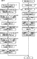
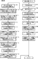
次に、図17のフローチャートを参照して、図3の記録再生機構部22による図14の処理によりフォーマットされた(初期化された)記録媒体81に情報を書き込む書込処理について説明する。
Next, a writing process for writing information to the
ステップS11において、ファイルシステム情報生成部62は、追記、または、更新されたファイルの属性などの情報に基づいて、ファイルシステム情報を生成し、読み込む。
In step S <b> 11, the file system
ステップS12において、ファイルシステム情報生成部62は、記録媒体81に対して最初の書込処理であるか否かを判定する。
In step S <b> 12, the file system
ステップS12において、例えば、最初の書込であると判定された場合、処理は、ステップS13に進み、ファイルシステム情報生成部62は、ECC符号化部71および変調部72を介して、書込部73に入力されるファイル(Stream+DB:ストリームデータと、そのストリームデータを管理するデータベースからなるファイル)を記録再生ブロック53により記録媒体81上のUser領域に書き込ませる。
For example, if it is determined in step S12 that the writing is the first writing, the process proceeds to step S13, and the file system
すなわち、図18の上段で示されるように、ファイルシステム情報生成部62は、ECC符号化部71および変調部72を介して、書込部73に入力されるファイル(図中のFiles(Steram+DB))を、記録媒体81上の上述したフォーマット処理により設定された領域B112に記録させる。尚、図18においては、上述したように、記録媒体81上が1層式のBD-Rの場合を示している。
That is, as shown in the upper part of FIG. 18, the file system
ステップS14において、ファイルシステム情報生成部62は、メインFSをECC符号化部71および変調部72を介して、書込部73に供給し、記録再生ブロック53により記録媒体81上のUser領域に書き込ませる。
In
すなわち、図18の上段で示されるように、ファイルシステム情報生成部62は、ファイルシステム情報をECC符号化部71および変調部72を介して、書込部73に供給し、記録媒体81上の上述したフォーマット処理により、メインFSを記録するために設定された領域B111内に記録させる(図中の「FS(Metadata)」として記録させる)。
That is, as shown in the upper part of FIG. 18, the file system
ステップS15において、ファイルシステム情報生成部62は、内周側のボリューム構造の情報およびアンカ情報をECC符号化部71および変調部72を介して、書込部73に供給し、記録再生ブロック53により記録媒体81上のUser領域に書き込ませる。
In
すなわち、図18の上段で示されるように、ファイルシステム情報生成部62は、ボリューム構造の情報およびアンカ情報をECC符号化部71および変調部72を介して、書込部73に供給し、記録媒体81上の上述したフォーマット処理により、メインFSに対応する内周側のボリューム構造の情報およびアンカ情報を記録するために設定された領域B111内に記録させる(図中の「Volume Str.」および「Anchor」として記録させる)。
That is, as shown in the upper part of FIG. 18, the file system
ステップS16において、ファイルシステム情報生成部62は、ミラーFSをECC符号化部71および変調部72を介して、書込部73に供給し、記録再生ブロック53により記録媒体81上のUser領域に書き込ませる。
In step S <b> 16, the file system
すなわち、図18の上段で示されるように、ファイルシステム情報生成部62は、ミラーFSをECC符号化部71および変調部72を介して、書込部73に供給し、記録媒体81上の上述したフォーマット処理により、ミラーFSを記録するために設定された領域B113内に記録させる(図中の「FS(MD-Mirror)」として記録させる)。
That is, as shown in the upper part of FIG. 18, the file system
ステップS17において、ファイルシステム情報生成部62は、外周側のボリューム構造の情報およびアンカ情報をECC符号化部71および変調部72を介して、書込部73に供給し、記録再生ブロック53により記録媒体81上のUser領域に書き込ませる。
In
すなわち、図18の上段で示されるように、ファイルシステム情報生成部62は、外周側のボリューム構造の情報およびアンカ情報をECC符号化部71および変調部72を介して、書込部73に供給し、記録媒体81上の上述したフォーマット処理により、ミラーFSに対応する外周側のボリューム構造の情報およびアンカ情報を記録するために設定された領域B113内に記録させる(図中の「Volume Str.」および2の「Anchor」として記録させる)。
That is, as shown in the upper part of FIG. 18, the file system
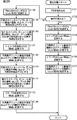
一方、ステップS12において、最初の書込ではないと判定された場合、すなわち、例えば、ステップS13乃至S17の処理により少なくとも1回以上情報が記録されている場合、その処理は、ステップS18に進む。 On the other hand, when it is determined in step S12 that it is not the first writing, that is, for example, when information is recorded at least once by the processing of steps S13 to S17, the processing proceeds to step S18.
ステップS18において、ファイルシステム情報生成部62は、ECC符号化部71および変調部72を介して、書込部73に入力されるファイル(Stream+DB:ストリームデータと、そのストリームデータを管理するデータベースからなるファイル)を記録再生ブロック53により記録媒体81上のUser領域に書き込ませる。
In step S18, the file system
すなわち、例えば、記録媒体81が図18の上段で示されるような状態で情報が記録されていた場合、図18の中段で示されるように、ファイルシステム情報生成部62は、ECC符号化部71および変調部72を介して、書込部73に入力されるファイル(図中のFiles(Steram+DB))を、記録媒体81上の上述したフォーマット処理により設定された領域B112'に記録させる。より詳細には、ファイルが追記であった場合、ファイルシステム情報生成部62は、図18の上段に示された領域B112に記録された情報に、新たに追記された情報を追加した情報を、図18の中段に示される領域B112'に記録する。また、新たな情報を更新したファイルを記録するような場合、図18の上段に示された領域B112に記録されたファイルを読出不能状態にし、新たに更新したファイルを領域B112に隣接する領域に記録するようにして領域B112'の情報を構成し、記録する。
That is, for example, when information is recorded in a state as shown in the upper part of FIG. 18, the file system
ステップS19において、ファイルシステム情報生成部62は、ECC符号化部71および変調部72を介して、書込部73を制御し、メインFS(FS(Metadata))およびボリューム構造の情報、および、アンカ情報を記録再生ブロック53により記録媒体81上から読出不可の状態にする。
In step S19, the file system
すなわち、図18の中段で示されるように、ファイルシステム情報生成部62は、領域B111に記録されているメインFS(FS(Metadata))およびボリューム構造の情報、および、アンカ情報を記録再生ブロック53により記録媒体81上から読出不可の状態にする。尚、図18においては、読出不可にされた領域については、黒地に白文字の表記がなされており、以降においても同様に表記するものとする。
That is, as shown in the middle part of FIG. 18, the file system
ステップS20において、ファイルシステム情報生成部62は、ステップS19の処理において、ファイルの追記または更新により生成される新たなメインFS(FS(Metadata))、ボリューム構造の情報、および、アンカ情報を上書きすることが可能な、最も近い位置のSA領域を検索する。
In step S20, the file system
すなわち、1層式のBR-Dの場合、SA領域は、外周側に設けられたOSAと内周側に設けられたISAのいずれかであるが、例えば、図18中段の場合、新たなメインFS(FS(Metadata))およびボリューム構造の情報、および、アンカ情報が記録でき、かつ、最も近いSA領域がISAであるとき、ファイルシステム情報生成部62は、ISAを記録可能な、最も近い領域として選択する。
That is, in the case of the single-layer BR-D, the SA area is either the OSA provided on the outer peripheral side or the ISA provided on the inner peripheral side. For example, in the case of the middle stage in FIG. When FS (FS (Metadata)) and volume structure information and anchor information can be recorded and the closest SA area is ISA, the file system
ステップS21において、ファイルシステム情報生成部62は、メインFSをECC符号化部71および変調部72を介して、書込部73に供給し、記録再生ブロック53により、ステップS20の処理により検索されたSA領域に書き込ませる。
In step S21, the file system
すなわち、図18の中段で示されるように、ファイルシステム情報生成部62は、ファイルシステム情報をECC符号化部71および変調部72を介して、書込部73に供給し、記録媒体81上のISA内の領域B111'に書き込ませる。
That is, as shown in the middle part of FIG. 18, the file system
さらに、ステップS22において、ファイルシステム情報生成部62は、メインFSに対応する内周側のボリューム構造の情報およびアンカ情報をECC符号化部71および変調部72を介して、書込部73に供給し、記録再生ブロック53にステップS20の処理により検索されたSA領域に書き込ませる。
Further, in step S22, the file system
すなわち、図18の中段で示されるように、ファイルシステム情報生成部62は、内周側のボリューム構造の情報およびアンカ情報をECC符号化部71および変調部72を介して、書込部73に供給し、記録媒体81上のISA内の領域B111'に書き込ませる。
That is, as shown in the middle part of FIG. 18, the file system
ステップS23において、ファイルシステム情報生成部62は、ECC符号化部71および変調部72を介して、書込部73を制御し、外周側に記録されているミラーFS(FS(MD-Mirror))、ボリューム構造の情報、および、アンカ情報を記録再生ブロック53により記録媒体81上から読出不可の状態にする。
In step S23, the file system
すなわち、図18の中段で示されるように、ファイルシステム情報生成部62は、領域B113に記録されているミラーFS(FS(MD-Mirror))、ボリューム構造の情報、および、アンカ情報を記録再生ブロック53により記録媒体81上から読出不可の状態にする。
That is, as shown in the middle part of FIG. 18, the file system
ステップS24において、ファイルシステム情報生成部62は、ステップS23の処理において、新たな外周側のミラーFS(FS(MD-Mirror))、ボリューム構造の情報、および、アンカ情報を記録可能な、最も近い位置のSA領域を検索する。
In step S24, the file system
すなわち、1層式のBR-Dの場合、SA領域は、外周側に設けられたOSAと内周側に設けられたISAのいずれかであるが、例えば、図18中段の場合、読出不可の状態にしたミラーFS(FS(MD-Mirror))、ボリューム構造の情報、および、アンカ情報が記録でき、かつ、最も近いSA領域がOSAであるとき、ファイルシステム情報生成部62は、OSAを記録可能な、最も近い領域として選択する。
That is, in the case of a single-layer BR-D, the SA area is either the OSA provided on the outer peripheral side or the ISA provided on the inner peripheral side. For example, in the case of the middle stage in FIG. When the mirror FS (FS (MD-Mirror)), volume structure information and anchor information can be recorded, and the nearest SA area is OSA, the file system
ステップS25において、ファイルシステム情報生成部62は、ミラーFSをECC符号化部71および変調部72を介して、書込部73に供給し、そのファイルシステム情報を記録再生ブロック53により、ステップS24の処理により検索されたSA領域に書き込ませる。
In step S25, the file system
すなわち、図18の中段で示されるように、ファイルシステム情報生成部62は、ミラーFSをECC符号化部71および変調部72を介して、書込部73に供給し、記録媒体81上のOSA内の領域B113'に書き込ませる。
That is, as shown in the middle part of FIG. 18, the file system
さらに、ステップS26において、ファイルシステム情報生成部62は、ミラーFSに対応する外周側のボリューム構造の情報およびアンカ情報をECC符号化部71および変調部72を介して、書込部73に供給し、記録再生ブロック53にステップS24の処理により検索されたSA領域に書き込ませる。
In step S26, the file system
すなわち、図18の中段で示されるように、ファイルシステム情報生成部62は、外周側のボリューム構造の情報およびアンカ情報をECC符号化部71および変調部72を介して、書込部73に供給し、記録媒体81上のOSA内の領域B113'に書き込ませる。
That is, as shown in the middle part of FIG. 18, the file system
さらに、図18の中段で示されるような記録媒体81に記録されたファイルを追記、または、更新するような場合、ステップS18において、図18の下段で示されるように、ファイルシステム情報生成部62は、ECC符号化部71および変調部72を介して、書込部73に入力されるファイル(図中のFiles(Steram+DB))を、記録媒体81上の上述したフォーマット処理により設定された領域B112''に記録させる。より詳細には、ファイルが追記であった場合、ファイルシステム情報生成部62は、図18の上段に示された領域B112'に記録された情報に、新たに追記された情報を追加した情報を、図18の下段に示される領域B112''に記録する。また、新たな情報を更新したファイルを記録するような場合、図18の中段に示された領域B112'に記録されたファイルを読出不能状態にし、新たに更新したファイルを領域B112'に隣接する領域に記録するようにして領域B112''の情報を構成し、記録する。
Further, when a file recorded on the
ステップS19において、図18の下段で示されるように、ファイルシステム情報生成部62は、領域B111'に記録されているメインFS(FS(Metadata))およびボリューム構造の情報、および、アンカ情報を記録再生ブロック53により記録媒体81上から読出不可の状態にする。
In step S19, as shown in the lower part of FIG. 18, the file system
ステップS20において、例えば、図18の下段の場合、新たなメインFS(FS(Metadata))およびボリューム構造の情報、および、アンカ情報が記録でき、かつ、最も近いSA領域がISAであるとき、ファイルシステム情報生成部62は、ISAを記録可能な、最も近い領域として選択する。
In step S20, for example, in the case of the lower part of FIG. 18, when a new main FS (FS (Metadata)) and volume structure information and anchor information can be recorded and the nearest SA area is ISA, The system
ステップS21において、図18の下段で示されるように、ファイルシステム情報生成部62は、メインFSをECC符号化部71および変調部72を介して、書込部73に供給し、記録媒体81上のISA内の領域B111''に書き込ませる。
In
さらに、ステップS22において、図18の下段で示されるように、ファイルシステム情報生成部62は、ボリューム構造の情報およびアンカ情報をECC符号化部71および変調部72を介して、書込部73に供給し、記録媒体81上のISA内の領域B111''に書き込ませる。
Further, in step S22, as shown in the lower part of FIG. 18, the file system
ステップS23において、図18の下段で示されるように、ファイルシステム情報生成部62は、領域B113'に記録されているミラーFS(FS(MD-Mirror))、ボリューム構造の情報、および、アンカ情報を記録再生ブロック53により記録媒体81上から読出不可の状態にする。
In step S23, as shown in the lower part of FIG. 18, the file system
ステップS24において、例えば、図18下段の場合、新たなミラーFS(FS(MD-Mirror))、ボリューム構造の情報、および、アンカ情報が記録でき、かつ、最も近いSA領域がOSAであるとき、ファイルシステム情報生成部62は、OSAを記録可能な、最も近い領域として選択する。
In step S24, for example, in the case of the lower part of FIG. 18, when a new mirror FS (FS (MD-Mirror)), volume structure information, and anchor information can be recorded, and the nearest SA area is OSA, The file system
ステップS25において、図18の下段で示されるように、ファイルシステム情報生成部62は、ミラーFSをECC符号化部71および変調部72を介して、書込部73に供給し、記録媒体81上のOSA内の領域B113''に書き込ませる。
In step S25, as shown in the lower part of FIG. 18, the file system
さらに、ステップS26において、図18の下段で示されるように、ファイルシステム情報生成部62は、ボリューム構造の情報およびアンカ情報をECC符号化部71および変調部72を介して、書込部73に供給し、記録媒体81上のOSA内の領域B113''に書き込ませる。
Further, in step S26, as shown in the lower part of FIG. 18, the file system
以上の処理により、ファイルが追記、または、更新される際、ファイルシステム情報、アンカ情報、および、ボリューム構造の情報の更新情報を順次SA領域の代替セクタに記録するようにしたので、ファイルシステム情報、アンカ情報、および、ボリューム構造の情報が物理的には異なる位置に順次記録されているにもかかわらず、記録されたファイルシステム情報、アンカ情報、および、ボリューム構造の情報の論理アドレスを変更させることなく、記録媒体に情報を記録させることが可能になる。また、ファイルの追記や更新の度に、ファイルシステム情報、アンカ情報、および、ボリューム構造の情報などの論理アドレスを書き換える必要がなくなる。結果として、同一の位置に上書きすることができない記録媒体、例えば、ライトアットワンスメディアに対しても、論理アドレス上の固定位置に記録することが義務付けられているような情報をあたかも上書き処理しているかのように扱うことが可能となる。 With the above process, when a file is added or updated, file system information, anchor information, and update information of volume structure information are sequentially recorded in the alternate sector of the SA area. The logical address of the recorded file system information, anchor information, and volume structure information is changed even though the anchor information and volume structure information are sequentially recorded at physically different positions. It is possible to record information on the recording medium without any problem. Further, it is not necessary to rewrite logical addresses such as file system information, anchor information, and volume structure information every time a file is added or updated. As a result, even for recording media that cannot be overwritten at the same location, for example, write-at-once media, information that is obliged to be recorded at a fixed location on the logical address is processed as if it were overwritten. It can be handled as if
尚、図17のフローチャートにおけるステップS13乃至S18,S21,S22,S25,S26における各記録処理においては、さらに詳細を後述する。 It should be noted that the recording processes in steps S13 to S18, S21, S22, S25, and S26 in the flowchart of FIG.
以上の例において、ファイルシステム情報は、更新された新たなファイルシステム情報が順次記録されていく例について記載してきたが、例えば、更新前のファイルシステム情報と、更新後のファイルシステム情報の差分情報のみ(例えば、変更のあったディレクトリの情報のみ)をSA領域に記録するようにしてもよい。このような場合、記録媒体81のファイルシステム情報は、更新前のファイルシステム情報と、差分情報とを用いることで生成することができる。結果として、SA領域に記録される情報量を節約することが可能になる。
In the above example, the file system information has been described as an example in which the updated new file system information is sequentially recorded. For example, the difference information between the file system information before the update and the file system information after the update. May be recorded in the SA area only (for example, only the information of the changed directory). In such a case, the file system information of the
また、ステップS20,S24の処理において、ファイルシステム情報、アンカ情報、および、ボリューム構造の情報が記録可能であって、最も近い位置のSA領域を検索する際、記録媒体81上の位置に応じて、最も近いSA領域は、ある程度決まっているので、それらの情報をまとめたテーブルなどを、例えば、フォーマット時に生成するようにして、SA領域を検索する際に利用するようにしても良い。このようにすることで、SA領域の検索処理をより高速で実現させることが可能となる。
Also, in the processing of steps S20 and S24, file system information, anchor information, and volume structure information can be recorded, and when searching for the nearest SA area, it is determined according to the position on the
さらに、以上においては、記録媒体81が1層式のBD-Rの場合について説明してきたが、例えば、記録媒体81が2層式のBD-Rである場合についても、ファイルシステム情報、アンカ情報、および、ボリューム構造の情報が記録可能であって、最も近い位置のSA領域を検索する際、物理的に距離が近ければ、検索されるSA領域は、層を跨ぐような関係であっても良い。すなわち、例えば、1層目のファイルシステム情報、アンカ情報、および、ボリューム構造の情報が記録可能であって、最も近いSA領域を検索する際、検索されるSA領域が、同一層における最も近い距離のSA領域よりも、2層目のSA領域の方が近い場合、2層目のSA領域が、選択されることになる。このようにすることで、更新されたファイルシステム情報、アンカ情報、および、ボリューム構造の情報を高速で読み出すことが可能となる。
Further, the case where the
また、以上においては、メインFSとミラーFSのそれぞれをSA領域に記録する例について説明してきたが、メインFSとミラーFSのそれぞれが、ファイルの追記や更新の度にSA領域に記録されることになるので、その分の領域をISAまたはOSAに確保する必要が生じ、結果として、記録媒体81上のUser領域が小さく制限される恐れがある。
Also, in the above, an example of recording each of the main FS and mirror FS in the SA area has been described. However, each of the main FS and mirror FS is recorded in the SA area each time a file is added or updated. Therefore, it is necessary to secure the corresponding area in the ISA or OSA, and as a result, the User area on the
そこで、メインFSとミラーFSのいずれか一方のみをSA領域に書き込むようにしても良い。 Therefore, only one of the main FS and the mirror FS may be written in the SA area.
図19は、ミラーFSとミラーFSに対応する内周側のファイルシステム情報、アンカ情報およびボリューム構造の情報のみをSA領域に書き込むようにした記録再生機構部22の構成を示している。尚、図19の記録再生機構部22において、図3の記録再生機構部22の構成と対応する構成については、同一の符号を付しており、その説明は適宜省略するものとする。
FIG. 19 shows a configuration of the recording /
図19の記録再生機構部22と図3の記録再生機構部22の構成において、異なるのは、制御部51に代えて、制御部301を設けた点である。制御部301は、制御部51のファイルシステム情報認識部61、ファイルシステム情報生成部62、代替情報管理部63、および代替情報生成部64に代えて、ファイルシステム情報認識部311、ファイルシステム情報生成部312、代替情報管理部313、および代替情報生成部314を備えている点で異なる。
In the configuration of the recording / reproducing
ファイルシステム情報認識部311は、基本的な機能は、ファイルシステム情報認識部51と同様であるが、ファイルシステム情報を認識する際、常に固定された論理アドレスからミラーFS、内周側のボリューム構造の情報、および、アンカ情報を読み出し、メインFS、外周側のボリューム構造の情報、および、アンカ情報をUser領域から読み出す。
The file system
ファイルシステム情報生成部312は、基本的な機能は、ファイルシステム情報生成部62と同様であるが、ファイルが追記、または、更新されたとき、メインFS、外周側のアンカ情報、および、ボリューム構造の情報のみをUser領域に記録すると共に、ミラーFS、内周側のアンカ情報、および、ボリューム構造の情報をSA領域に記録する。
The file system
ファイルシステム情報生成部312の初期化部312aは、初期化部62aと基本的に同様であるが、ミラーFSとメインFSの配置を、内周側と外周側とで入れ替えた状態にフォーマットする。すなわち、後述する図21の上段で示されるように、ミラーFSと対応するアンカ情報およびボリューム構造の情報は、領域B131に設定され、メインFSと対応するアンカ情報およびボリューム構造の情報は、領域B133に設定される。尚、図21においては、内周側のボリューム構造の情報およびアンカ情報、メインFS、並びに、ファイル、ミラーFS、アンカ情報、およびボリューム構造の情報が、それぞれ1のSRRとして設定される。
The
尚、この例においては、ファイルが追記、または、更新された際、ミラーFS、内周側のアンカ情報、および、ボリューム構造の情報のみがSA領域に記録され、メインFS、外周側のアンカ情報、および、ボリューム構造の情報がUser領域に記録される例について説明するが、メインFS、外周側のアンカ情報、および、ボリューム構造の情報のみをSA領域に記録し、ミラーFS、内周側のアンカ情報、および、ボリューム構造の情報をUser領域に記録するようにしても良い。 In this example, when a file is added or updated, only the mirror FS, inner anchor information, and volume structure information are recorded in the SA area, and the main FS, outer anchor information. An example in which volume structure information is recorded in the User area will be described. However, only the main FS, outer anchor information, and volume structure information are recorded in the SA area, and the mirror FS, inner periphery information is recorded. Anchor information and volume structure information may be recorded in the User area.
尚、代替情報管理部313、メモリ313a、代替情報生成部314、およびメモリ314aは、図3の代替情報管理部63、メモリ63a、代替情報生成部64、およびメモリ64aと同様であるのでその説明は省略する。
The replacement
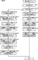
次に、図20のフローチャートを参照して、図19の記録再生機構部22による書込処理について説明する。
Next, the writing process by the recording / reproducing
尚、図20のフローチャートのステップS41乃至S49の処理、および、ステップS52乃至S55の処理は、図17のフローチャートを参照して説明したステップS11乃至S19の処理、および、ステップS23乃至S26の処理と同様であるので、その説明は省略する。 Note that the processes of steps S41 to S49 and the processes of steps S52 to S55 in the flowchart of FIG. 20 are the same as the processes of steps S11 to S19 and the processes of steps S23 to S26 described with reference to the flowchart of FIG. Since it is the same, the description is abbreviate | omitted.
ステップS41において、ファイルシステム情報が読み込まれ、ステップS42において、最初の書込であるか否かが判定され、例えば、最初の処理である場合、ステップS43において、図21の上段で示されるように、記録されたファイル(図中のFiles(Stream+DB)がUser領域の領域B132に記録される。ステップS44において、例えば、図21の上段で示されるようにメインFS(図中のFS(Metadata))が、User領域の領域B133に記録される。ステップS45において、メインFSに対応する外周側のボリューム構造の情報(図中のVolume Str.)、および、アンカ情報(図中のAnchor)が、User領域の領域B133に記録される。ステップS46において、ミラーFS(図中のFS(MD-Mirror))がUser領域の領域B131に記録される。ステップS47において、ミラーFSに対応する内周側のボリューム構造の情報(図中のVolume Str.)、および、アンカ情報(図中のAnchor)が、User領域の領域B131に記録される。
In step S41, the file system information is read, and in step S42, it is determined whether or not it is the first writing. For example, in the case of the first processing, in step S43, as shown in the upper part of FIG. , The recorded file (Files (Stream + DB) in the figure is recorded in the area B132 of the User area. In step S44, for example, as shown in the upper part of FIG. 21, the main FS (FS (Metadata )) Is recorded in the
さらに、ステップS42において、上述したステップS43乃至S47の処理によりファイルが記録されて、その後、そのファイルが追記された場合、ステップS48において、図21の中段で示されるように、追記されたファイル(図中のFiles(Stream+DB)がUser領域の領域B132'に追記される。ステップS49において、直前に記述されたメインFS、外周側のボリューム構造の情報、およびアンカ情報が読出不可に設定される。 Furthermore, in step S42, when a file is recorded by the processing of steps S43 to S47 described above, and then the file is additionally written, in step S48, as shown in the middle part of FIG. Files (Stream + DB) in the figure are added to the area B132 ′ of the User area In step S49, the main FS, the volume structure information on the outer peripheral side, and the anchor information described immediately before are set to unreadable. The
ステップS50において、ファイルシステム情報生成部312は、メインFSをECC符号化部71および変調部72を介して、書込部73に供給し、記録再生ブロック53により、図21の中段で示されるように、User領域の領域B133'に書き込ませる。
In step S50, the file system
さらに、ステップS51において、ファイルシステム情報生成部312は、メインFSに対応する外周側のボリューム構造の情報およびアンカ情報をECC符号化部71および変調部72を介して、書込部73に供給し、図21の中段で示されるように、User領域の領域B133'に書き込ませる。
Further, in step S51, the file system
そして、ステップS52において、図21の中段の領域B131'に記録されているミラーFS(FS(MD-Mirror))、内周側のボリューム構造の情報、および、アンカ情報が読出不可の状態にされる。ステップS53において、ミラーFS、内周側のボリューム構造の情報、および、アンカ情報が記録された位置から記録可能な最も近い位置のSA領域が検索される。例えば、図21の中段の場合、記録可能な最も近い位置のSA領域としてISAが検索される。 In step S52, the mirror FS (FS (MD-Mirror)), the volume structure information on the inner peripheral side, and the anchor information recorded in the middle area B131 ′ of FIG. The In step S53, the SA area at the nearest recordable position from the position where the mirror FS, the volume structure information on the inner circumference side, and the anchor information are recorded is searched. For example, in the middle of FIG. 21, the ISA is searched for as the nearest recordable SA area.
ステップS54,S55において、ミラーFSと、ミラーFSに対応する内周側のアンカ情報、および、ボリューム構造の情報が、図21の中段で示されるように、検索されたISAの領域B131'に記録される。 In steps S54 and S55, the mirror FS, the inner-side anchor information corresponding to the mirror FS, and the volume structure information are recorded in the searched ISA area B131 ′ as shown in the middle of FIG. Is done.
さらに、この状態でファイルが追記された場合、ステップS48において、図21の下段で示されるように、追記されたファイル(図中のFiles(Stream+DB)がUser領域の領域B132''に追記される。ステップS49において、直前に領域B133'に記述されたメインFS、外周側のボリューム構造の情報、およびアンカ情報が読出不可に設定される。 Further, when a file is added in this state, in step S48, as shown in the lower part of FIG. 21, the added file (Files (Stream + DB) in the figure is added to the area B132 ″ of the User area). In step S49, the main FS described in the area B133 ′ immediately before, the information on the volume structure on the outer peripheral side, and the anchor information are set to be unreadable.
ステップS50において、ファイルシステム情報生成部312は、メインFSをECC符号化部71および変調部72を介して、書込部73に供給し、記録再生ブロック53により、図21の下段で示されるように、User領域の領域B133''に書き込ませる。
In step S50, the file system
さらに、ステップS51において、ファイルシステム情報生成部312は、メインFSに対応する外周側のボリューム構造の情報およびアンカ情報をECC符号化部71および変調部72を介して、書込部73に供給し、図21の下段で示されるように、User領域の領域B133''に書き込ませる。
Further, in step S51, the file system
そして、ステップS52において、図21の下段の領域B131'に記録されているミラーFS(FS(MD-Mirror))、内周側のボリューム構造の情報、および、アンカ情報が読出不可の状態にされる。ステップS53において、ミラーFS、内周側のボリューム構造の情報、および、アンカ情報が記録された位置から記録可能な最も近い位置のSA領域が検索される。例えば、図21の下段の場合、記録可能な最も近い位置のSA領域としてISAが検索される。 In step S52, the mirror FS (FS (MD-Mirror)), the volume structure information on the inner circumference, and the anchor information recorded in the lower area B131 ′ of FIG. The In step S53, the SA area at the nearest recordable position from the position where the mirror FS, the volume structure information on the inner circumference side, and the anchor information are recorded is searched. For example, in the lower part of FIG. 21, the ISA is searched as the nearest recordable SA area.
ステップS54,S55において、ミラーFSと、ミラーFSに対応する内周側のアンカ情報、および、ボリューム構造の情報が、図21の下段で示されるように、検索されたISAの領域のB131''に記録される。 In steps S54 and S55, the mirror FS, the anchor information on the inner circumference side corresponding to the mirror FS, and the volume structure information are retrieved as shown in the lower part of FIG. To be recorded.
以上のような処理により、ファイルが追記または更新された場合、ミラーFSと、そのミラーFSに対応する内周側のアンカ情報およびボリューム構造の情報のみがSA領域に記録されることになるので、SA領域が消費される容量を、図3の記録再生機構部22における場合と比べて、約半分にすることが可能となる。ただし、この場合、メインFSと、メインFSに対応するアンカ情報およびボリューム構造の情報は、記録される位置が、例えば、図21で示されるように、領域B133,B133',B133''の順に変更されることになるので、論理アドレスを変更する必要がある。そこで、このような場合、通常は、ミラーFSを読み出すようにして、固定された論理アドレス上に記録されたミラーFSを取得し、何らかの事情により、ミラーFSが読み出せないときにのみ、User領域に記録されたメインFSを読み出すようにすることで、固定された論理アドレスからファイルシステム情報を読み出すメリットと、2重にFSを構成するメリットを生かしつつ、SA領域を節約するようにすることが可能となる。
When a file is appended or updated by the above process, only the mirror FS and the anchor information and volume structure information on the inner periphery corresponding to the mirror FS are recorded in the SA area. Compared with the case of the recording / reproducing
尚、図20のフローチャートにおけるステップS43乃至S48,S50,S51,S54,S55における各記録処理については、さらに詳細を後述する。 The details of each recording process in steps S43 to S48, S50, S51, S54, and S55 in the flowchart of FIG. 20 will be described later.
以上においては、同一のメインFSとミラーFSを、それぞれ配置することで、2重にFSを配置する例について説明してきたが、ファイルが追記、または、更新されるときには、メインとなるファイルシステム情報のみをUser領域に記録すると共に、内周側のボリューム構造の情報およびアンカ情報のみをSA領域に記録するようにすることで、さらに、SA領域の使用量を節約するようにしても良い。 In the above, an example in which the same main FS and mirror FS are respectively arranged to double the FS has been described. However, when a file is added or updated, main file system information In addition, only the volume structure information and the anchor information on the inner circumference side may be recorded in the SA area, and the usage amount of the SA area may be further saved.
図22は、ファイルが追記、または、更新されるときには、メインFSのみをUser領域に記録すると共に、内周側のボリューム構造の情報およびアンカ情報のみをSA領域に記録するようにするようにした記録再生機構部22の構成を示している。尚、図22の記録再生機構部22において、図19の記録再生機構部22の構成と対応する構成については、同一の符号を付しており、その説明は適宜省略するものとする。
In FIG. 22, when a file is added or updated, only the main FS is recorded in the User area, and only the volume structure information and anchor information on the inner circumference side are recorded in the SA area. The structure of the recording / reproducing
図22の記録再生機構部22と図19の記録再生機構部22の構成において、異なるのは、制御部301に代えて、制御部331を設けた点である。制御部331は、制御部301のファイルシステム情報認識部311、ファイルシステム情報生成部312、代替情報管理部313、および代替情報生成部314に代えて、ファイルシステム情報認識部341、ファイルシステム情報生成部342、代替情報管理部343、および代替情報生成部344をそれぞれ備えている点で異なる。
22 differs from the recording / reproducing
ファイルシステム情報認識部341は、基本的な機能は、ファイルシステム情報認識部311と同様であるが、ファイルシステム情報を認識する際、メインFS、外周側のボリューム構造の情報、および、アンカ情報を読み出す。尚、図22の例においては、単独のメインFSのみが記録されるので、読み出せるのは、ここでは、ファイルシステム情報認識部341は、ファイルシステム情報としてメインFSを読み出すことしかできない。
The file system
ファイルシステム情報生成部342は、基本的な機能は、ファイルシステム情報生成部62と同様であるが、ファイルが追記、または、更新されたとき、単独のファイルシステム情報、外周側のアンカ情報、および、ボリューム構造の情報をUser領域に記録させると共に、内周側のアンカ情報、および、ボリューム構造の情報をSA領域に記録させる。
The file system
ファイルシステム情報生成部342の初期化部342aは、初期化部312aと基本的に同様であるが、初期化部312aと異なり、単独のメインFSを、User領域に設定する。すなわち、後述する図24の上段で示されるように、単独のメインFSと、外周側のアンカ情報およびボリューム構造の情報は、領域B153に設定され、内周側のアンカ情報およびボリューム構造の情報は、領域B151に設定される。尚、図24においては、内周側のボリューム構造の情報およびアンカ情報、並びに、メインFS、ファイル、ミラーFS、アンカ情報、およびボリューム構造の情報が、それぞれ1のSRRとして設定される。
The
尚、代替情報管理部343、メモリ343a、代替情報生成部344、およびメモリ344aは、図3の代替情報管理部63、メモリ63a、代替情報生成部64、およびメモリ64aと同様であるのでその説明は省略する。
The replacement
次に、図23のフローチャートを参照して、図22の記録再生機構部22による書込処理について説明する。
Next, the writing process by the recording / reproducing
尚、図23のフローチャートのステップS71乃至S81の処理は、図20のフローチャートを参照して説明したステップS41乃至S45の処理、および、ステップS47乃至S51の処理と同様であるので、その説明は省略する。 Note that the processing of steps S71 to S81 in the flowchart of FIG. 23 is the same as the processing of steps S41 to S45 and the processing of steps S47 to S51 described with reference to the flowchart of FIG. To do.
ステップS71において、ファイルシステム情報が読み込まれ、ステップS72において、最初の書込であるか否かが判定され、例えば、最初の処理である場合、ステップS73において、図24の上段で示されるように、記録されたファイル(図中のFiles(Stream+DB))がUser領域の領域B152に記録される。ステップS74において、例えば、図24の上段で示されるように(単独の)メインFS(図中のFS(Metadata))が、User領域の領域B153に記録される。ステップS75において、外周側のボリューム構造の情報(図中のVolume Str.)、および、アンカ情報(図中のAnchor)が、User領域の領域B153に記録される。ステップS76において、内周側のボリューム構造の情報(図中のVolume Str.)、および、アンカ情報(図中のAnchor)が、User領域の領域B151に記録される。 In step S71, the file system information is read. In step S72, it is determined whether or not it is the first writing. For example, in the case of the first processing, in step S73, as shown in the upper part of FIG. The recorded file (Files (Stream + DB) in the figure) is recorded in the area B152 of the User area. In step S74, for example, as shown in the upper part of FIG. 24, a (single) main FS (FS (Metadata) in the figure) is recorded in the area B153 of the User area. In step S75, information on the volume structure on the outer peripheral side (Volume Str. In the figure) and anchor information (Anchor in the figure) are recorded in the area B153 of the User area. In step S76, information on the volume structure on the inner circumference side (Volume Str. In the figure) and anchor information (Anchor in the figure) are recorded in the area B151 of the User area.
さらに、ステップS72において、上述したステップS73乃至S76の処理によりファイルが記録されて、その後、そのファイルが追記された場合、ステップS77において、図24の中段で示されるように、追記されたファイル(図中のFiles(Stream+DB))がUser領域の領域B152'に追記される。ステップS78において、直前に領域B153に記述されていたメインFS、外周側のボリューム構造の情報、およびアンカ情報が読出不可に設定される。 Further, in step S72, when a file is recorded by the above-described processing of steps S73 to S76, and then the file is additionally written, in step S77, as shown in the middle part of FIG. Files (Stream + DB) in the figure is added to the area B152 ′ of the User area. In step S78, the main FS described in the area B153 immediately before, the volume structure information on the outer peripheral side, and the anchor information are set to be unreadable.
ステップS79において、ファイルシステム情報が、図24の中段で示されるように、User領域の領域B153'に書き込まれる。さらに、ステップS80において、外周側のボリューム構造の情報およびアンカ情報が、図24の中段で示されるように、User領域の領域B153'に書き込まれる。 In step S79, the file system information is written in the area B153 ′ of the User area as shown in the middle part of FIG. Further, in step S80, the volume structure information and anchor information on the outer peripheral side are written in the area B153 ′ of the User area as shown in the middle part of FIG.
さらに、ステップS81において、ファイルシステム情報生成部342は、図24の中段の領域B151に記録されている内周側のボリューム構造の情報、および、アンカ情報を読出不可の状態にする。
Further, in step S81, the file system
ステップS82において、ファイルシステム情報生成部342は、内周側のボリューム構造の情報、および、アンカ情報が記録された位置から記録可能な最も近い位置のSA領域を検索する。例えば、図24の中段の場合、記録可能な最も近い位置のSA領域としてISAが検索される。
In step S82, the file system
ステップS83において、ファイルシステム情報生成部342は、内周側のアンカ情報、および、ボリューム構造の情報を、図24の中段で示されるように、検索されたISAの領域B151'に記録させる。
In step S83, the file system
さらに、この状態でファイルが追記された場合、ステップS77において、図24の下段で示されるように、追記されたファイル(図中のFiles(Stream+DB))がUser領域の領域B152''に追記される。ステップS78において、直前に領域B153'に記述されたメインFS、ボリューム構造の情報、およびアンカ情報が読出不可に設定される。 Further, when a file is added in this state, in step S77, the added file (Files (Stream + DB) in the figure) is stored in the area B152 ″ of the User area as shown in the lower part of FIG. It is added. In step S78, the main FS, volume structure information, and anchor information described immediately before in the area B153 ′ are set to be unreadable.
ステップS79において、メインFSが、図24の下段で示されるように、User領域の領域B153''に書き込まれる。 In step S79, the main FS is written in the area B153 ″ of the User area as shown in the lower part of FIG.
さらに、ステップS80において、ファイルシステム情報生成部312は、外周側のボリューム構造の情報およびアンカ情報が、図24の下段で示されるように、User領域の領域B153''に書き込まれる。
Further, in step S80, the file system
そして、ステップS81において、図24の下段の領域B151'に記録されている内周側のボリューム構造の情報、および、アンカ情報が読出不可の状態にされる。ステップS82において、内周側のボリューム構造の情報、および、アンカ情報が記録された位置から記録可能な最も近い位置のSA領域が検索される。例えば、図24の下段の場合、記録可能な最も近い位置のSA領域としてISAが検索される。 In step S81, the volume structure information and the anchor information on the inner circumference recorded in the lower area B151 ′ of FIG. 24 are made unreadable. In step S82, the nearest SA area that can be recorded is searched from the position where the volume structure information and the anchor information on the inner circumference side are recorded. For example, in the lower part of FIG. 24, the ISA is searched as the nearest recordable SA area.
ステップS83において、内周側のアンカ情報、および、ボリューム構造の情報が、図24の下段で示されるように、検索されたISAの領域のB151''に記録される。 In step S83, the inner circumference anchor information and the volume structure information are recorded in B151 ″ of the searched ISA area, as shown in the lower part of FIG.
以上のような処理により、ファイルが追記または更新された場合、内周側のアンカ情報およびボリューム構造の情報のみがSA領域に記録されることになるので、固定された論理アドレス上のボリューム構造の情報、および、アンカ情報を読み出すことが可能となる。また、SA領域が消費される容量を、図3または図19の記録再生機構部22における場合と比べて、さらに節約することが可能となる。ただし、この場合も、メインFSと、外周側のアンカ情報およびボリューム構造の情報は、記録される位置が、例えば、図24で示されるように、領域B153,B153',B153''の順に変更されることになるので、論理アドレスを変更する必要がある。
When a file is appended or updated by the above process, only the anchor information and volume structure information on the inner circumference side are recorded in the SA area, so the volume structure on the fixed logical address is recorded. Information and anchor information can be read out. Further, it is possible to further save the capacity consumed by the SA area as compared with the case of the recording / reproducing
尚、図23のフローチャートにおけるステップS73乃至S77,S79,S80,S83における各記録処理については、さらに詳細を後述する。 The details of the recording processes in steps S73 to S77, S79, S80, and S83 in the flowchart of FIG. 23 will be described later.
尚、以上においては、ボリュームスペースの先頭部分にファイルシステム情報(メインFSおよびミラーFSの両方またはメインFSのみ)、ボリューム構造の情報およびアンカ情報、または、ボリューム構造の情報およびアンカ情報を設定し、更新のある度に、SA領域に記録する例について説明してきたが、情報は、これらの組み合わせに限らず、例えば、ファイルシステム情報、ボリューム構造の情報またはアンカ情報のうちのいずれか1であってもよい。 In the above, file system information (both main FS and mirror FS or main FS only), volume structure information and anchor information, or volume structure information and anchor information are set at the beginning of the volume space. Although an example of recording in the SA area each time there is an update has been described, the information is not limited to a combination of these, for example, any one of file system information, volume structure information or anchor information Also good.
また、ボリュームスペースの先頭部分にファイルシステム情報、ボリューム構造の情報またはアンカ情報のいずれかをSA領域に記録するようにして、論理アドレスを変更することなく、ファイルの追記または更新に伴うファイルシステム情報、ボリューム構造の情報、または、アンカ情報の更新を実行することにより、ファイルシステム情報、ボリューム構造の情報、または、アンカ情報を読み出せるようにする例について説明してきたが、さらに、ファイルの追記、または、更新の際に、ファイルの一部をもSA領域に記録するようにしても良い。 In addition, file system information, volume structure information, or anchor information is recorded in the SA area at the beginning of the volume space, and file system information that accompanies the addition or update of files without changing the logical address. In the above example, the file system information, the volume structure information, or the anchor information can be read by executing the update of the volume structure information or the anchor information. Alternatively, a part of the file may be recorded in the SA area when updating.
図25は、ファイルの追記、または、更新の際に、ファイルシステム情報、ボリューム構造の情報、および、アンカ情報に加えて、ファイルの一部をもSA領域に記録するようにした記録再生機構部22の構成を示している。 FIG. 25 shows a recording / playback mechanism unit that records a part of a file in the SA area in addition to file system information, volume structure information, and anchor information when a file is added or updated. 22 configurations are shown.
尚、図25の記録再生機構部22において、図3の記録再生機構部22の構成と対応する構成については、同一の符号を付しており、その説明は適宜省略するものとする。
In the recording / reproducing
図25の記録再生機構部22と図3の記録再生機構部22の構成において、異なるのは、制御部51に代えて、制御部351を設けた点である。制御部351は、制御部351のファイルシステム情報認識部61、ファイルシステム情報生成部62、代替情報管理部63、および代替情報生成部64に代えて、ファイルシステム情報認識部361、ファイルシステム情報生成部362、代替情報管理部363、および代替情報生成部364を備えている点で異なる。
25 differs from the recording / reproducing
ファイルシステム情報認識部361は、基本的な機能は、ファイルシステム情報認識部51と同様であるが、ファイルシステム情報を認識する際、常に固定された論理アドレスから内周側のISAに記録されたファイルシステム情報、ボリューム構造の情報、アンカ情報、および、ファイル(ストリームデータのデータベースDB:以降においては、ファイル(DB)と称する)を読み出し、外周側のファイルシステム情報、ボリューム構造の情報、および、アンカ情報をUser領域から読み出す。
The basic function of the file system
ファイルシステム情報生成部362は、基本的な機能は、ファイルシステム情報生成部62と同様であるが、ファイルが追記、または、更新されたとき、内周側のファイルシステム情報、アンカ情報、ボリューム構造の情報、および、ファイル(DB)をSA領域に記録すると共に、外周側のファイルシステム情報、アンカ情報、および、ボリューム構造の情報をUser領域に記録する。
The file system
ファイルシステム情報生成部362の初期化部362aは、初期化部62aと基本的に同様であるが、フォーマットの際、ファイルをストリームデータ(Files(Stream))とデータベース(Files(DB))とに分けて設定する。すなわち、後述する図27の上段で示されるように、メインFS(FS(Metadata))と対応するアンカ情報およびボリューム構造の情報に加えて、データベース情報(Files(DB))は、領域B171に設定され、ミラーFS(FS(MD-Mirror))と対応するアンカ情報およびボリューム構造の情報は、領域B173に設定される。
The
尚、代替情報管理部363、メモリ363a、代替情報生成部364、およびメモリ364aは、図3の代替情報管理部63、メモリ63a、代替情報生成部64、およびメモリ64aと同様であるのでその説明は省略する。
The replacement
次に、図26のフローチャートを参照して、図25の記録再生機構部22による書込処理について説明する。
Next, the writing process by the recording / reproducing
尚、図26のフローチャートのステップS101,S102の処理、ステップS105乃至S108、および、ステップS113乃至S118の処理については、図17のフローチャートを参照して説明したステップS11,S12の処理、ステップS14乃至S17の処理、および、ステップS21乃至S26の処理と同様であるので、その説明は省略する。 In addition, about the process of step S101, S102 of the flowchart of FIG. 26, the process of step S105 thru | or S108, and step S113 thru | or S118, the process of step S11, S12 demonstrated with reference to the flowchart of FIG. Since it is the same as the process of S17 and the process of step S21 thru | or S26, the description is abbreviate | omitted.
ステップS101において、ファイルシステム情報FSが読み込まれ、ステップS102において、最初の書込であるか否かが判定され、例えば、最初の処理である場合、ステップS103において、ファイルシステム情報生成部362は、ECC符号化部71および変調部72を介して、書込部73に入力されるストリームデータ(Files(Stream))を記録再生ブロック53により記録媒体81上のUser領域に書き込ませる。
In step S101, the file system information FS is read. In step S102, it is determined whether or not it is the first writing. For example, in the case of the first process, in step S103, the file system
すなわち、図27の上段で示されるように、ファイルシステム情報生成部362は、ECC符号化部71および変調部72を介して、書込部73に入力されるファイル(図中のFiles(Stream))を、記録媒体81上の上述したフォーマット処理により設定された領域B172に記録させる。
That is, as shown in the upper part of FIG. 27, the file system
ステップS104において、ファイルシステム情報生成部362は、ECC符号化部71および変調部72を介して、書込部73に入力されるデータベース(Files(DB):ストリームデータを管理するためのデータベース)を記録再生ブロック53により記録媒体81上のUser領域に書き込ませる。
In step S104, the file system
すなわち、図27の上段で示されるように、ファイルシステム情報生成部362は、ECC符号化部71および変調部72を介して、書込部73に入力されるファイル(図中のFiles(Steram+DB))を、記録媒体81上の上述したフォーマット処理により設定された領域B171に記録させる。
That is, as shown in the upper part of FIG. 27, the file system
ステップS105において、例えば、図27の上段で示されるようにメインFS(図中のFS(Metadata))が、User領域の領域B171に記録される。ステップS106において、メインFSに対応する内周側のボリューム構造の情報(図中のVolume Str.)、および、アンカ情報(図中のAnchor)が、User領域の領域B171に記録される。ステップS107において、ミラーFS(図中のFS(MD-Mirror))がUser領域の領域B173に記録される。ステップS108において、ミラーFSに対応する外周側のボリューム構造の情報(図中のVolume Str.)、および、アンカ情報(図中のAnchor)が、User領域の領域B173に記録される。 In step S105, for example, as shown in the upper part of FIG. 27, the main FS (FS (Metadata) in the figure) is recorded in the area B171 of the User area. In step S106, information on the volume structure on the inner periphery side corresponding to the main FS (Volume Str. In the figure) and anchor information (Anchor in the figure) are recorded in the area B171 of the User area. In step S107, the mirror FS (FS (MD-Mirror) in the figure) is recorded in the area B173 of the User area. In step S108, information on the volume structure on the outer circumference side corresponding to the mirror FS (Volume Str. In the figure) and anchor information (Anchor in the figure) are recorded in the area B173 of the User area.
さらに、ステップS102において、上述したステップS103乃至S108の処理によりファイルが記録されて、その後、そのファイルが追記、または、更新された場合、その処理は、ステップS109に進む。 Furthermore, in step S102, when a file is recorded by the processing of steps S103 to S108 described above, and then the file is added or updated, the processing proceeds to step S109.
ステップS109において、ファイルシステム情報生成部362は、ECC符号化部71および変調部72を介して、書込部73に入力されるファイル(Stream:ストリームデータからなるファイル)を記録再生ブロック53により記録媒体81上のUser領域に書き込ませる。
In step S109, the file system
すなわち、例えば、記録媒体81が図27の上段で示されるような状態で情報が記録されていた場合、図27の中段で示されるように、ファイルシステム情報生成部62は、ECC符号化部71および変調部72を介して、書込部73に入力されるファイル(図中のFiles(Stream))を、記録媒体81上の上述したフォーマット処理により設定された領域B172'に記録させる。より詳細には、ファイルが追記であった場合、ファイルシステム情報生成部362は、図27の上段に示された領域B172に記録された情報に、新たに追記された情報を追加した情報を、図27の中段に示される領域B172'に記録する。また、新たな情報を更新したファイルを記録するような場合、図27の上段に示された領域B172に記録されたファイルを読出不能状態にし、新たに更新したファイルを領域B172に隣接する領域に記録するようにして領域B172'の情報を構成し、記録する。
That is, for example, when information is recorded in a state as shown in the upper part of FIG. 27, the file system
ステップS110において、ファイルシステム情報生成部362は、ECC符号化部71および変調部72を介して、書込部73を制御し、メインFS(FS(Metadata))、内周側のボリューム構造の情報、アンカ情報、および、Files(DB)を記録再生ブロック53により記録媒体81上から読出不可の状態にする。
In step S110, the file system
すなわち、図27の中段で示されるように、ファイルシステム情報生成部362は、領域B171に記録されているメインFS(FS(Metadata))、ボリューム構造の情報、アンカ情報、および、Files(DB)(ファイルが追記または更新される際に更新されたデータベースファイル)を記録再生ブロック53により記録媒体81上から読出不可の状態にする。
That is, as shown in the middle part of FIG. 27, the file system
ステップS111において、ファイルシステム情報生成部362は、ステップS110の処理において、新たなメインFS(FS(Metadata))、ボリューム構造の情報、アンカ情報、および、データベースファイル(Files(DB))を上書きすることが可能な、最も近い位置のSA領域を検索する。
In step S111, the file system
すなわち、1層式のBR-Dの場合、SA領域は、外周側に設けられたOSAと内周側に設けられたISAのいずれかであるが、例えば、図27中段の場合、新たなメインFS(FS(Metadata))、ボリューム構造の情報、アンカ情報、および、ファイルFiles(DB)が記録でき、かつ、最も近いSA領域がISAであるとき、ファイルシステム情報生成部362は、ISAを記録可能な、最も近い領域として選択する。
That is, in the case of the single-layer BR-D, the SA area is either the OSA provided on the outer peripheral side or the ISA provided on the inner peripheral side. For example, in the case of the middle stage in FIG. When FS (FS (Metadata)), volume structure information, anchor information, and file Files (DB) can be recorded, and the nearest SA area is ISA, the file system
ステップS112において、ファイルシステム情報生成部312は、データベースファイル(Files(DB))を検索されたSA領域に記録する。すなわち、例えば、図27の中段で示されるように、ファイルシステム情報生成部362は、検索されたSA領域であるISA上の領域B171'にデータベースファイル(Files(DB))を記録する。
In step S112, the file system
ステップS113において、ファイルシステム情報生成部362は、メインFSを検索されたSA領域に記録する。すなわち、例えば、図27の中段で示されるように、ファイルシステム情報生成部312は、検索されたSA領域であるISA上の領域B171'にファイルシステム情報を記録する。
In step S113, the file system
ステップS114において、メインFSに対応するボリューム構造の情報およびアンカ情報が、図27の中段で示されるように、SA領域の領域B171'に書き込まれる。
In step S114, the volume structure information and anchor information corresponding to the main FS are written into the
ステップS115において、図27の中段の領域B173に記録されているミラーFS(FS(MD-Mirror))、外周側のボリューム構造の情報、および、アンカ情報が読出不可の状態にされる。ステップS116において、新たなミラーFS、ボリューム構造の情報、および、アンカ情報が記録可能な最も近い位置のSA領域が検索される。例えば、図27の中段の場合、記録可能な最も近い位置のSA領域としてOSAが検索される。 In step S115, the mirror FS (FS (MD-Mirror)), the volume structure information on the outer peripheral side, and the anchor information recorded in the middle area B173 in FIG. 27 are made unreadable. In step S116, the SA area at the nearest position where the new mirror FS, volume structure information, and anchor information can be recorded is searched. For example, in the middle of FIG. 27, OSA is searched for as the nearest recordable SA area.
ステップS117,S118において、ミラーFSと、外周側のアンカ情報、および、ボリューム構造の情報が、図27の中段で示されるように、検索されたOSAの領域B173'に記録される。 In steps S117 and S118, the mirror FS, the outer anchor information, and the volume structure information are recorded in the searched OSA area B173 ′ as shown in the middle of FIG.
さらに、この状態でファイルが追記された場合、ステップS109において、図27の下段で示されるように、追記されたファイル(図中のFiles(Stream)がUser領域の領域B172''に追記される。ステップS110において、直前に領域B171'に記述されたメインFS、内周側のボリューム構造の情報、およびアンカ情報が読出不可に設定される。 Further, when a file is added in this state, in step S109, as shown in the lower part of FIG. 27, the added file (Files (Stream) in the figure is added to the area B172 ″ of the User area). In step S110, the main FS, the inner peripheral volume structure information, and the anchor information described in the area B171 ′ immediately before are set to be unreadable.
ステップS111において、ステップS110の処理により、新たなメインFS(FS(Metadata))、ボリューム構造の情報、アンカ情報、および、データベースファイル(Files(DB))を記録することが可能な、最も近い位置のSA領域が検索される。例えば、図27の下段の場合、新たなメインFS(FS(Metadata))、ボリューム構造の情報、アンカ情報、および、ファイルFiles(DB)が記録でき、かつ、最も近いSA領域がISAであるとき、ファイルシステム情報生成部362は、ISAを記録可能な、最も近い領域として選択する。
In step S111, the closest position at which a new main FS (FS (Metadata)), volume structure information, anchor information, and database file (Files (DB)) can be recorded by the process of step S110. SA area is searched. For example, in the lower case of FIG. 27, a new main FS (FS (Metadata)), volume structure information, anchor information, and file Files (DB) can be recorded, and the nearest SA area is ISA. The file system
ステップS112において、データベースファイル(Files(DB))が検索されたSA領域に記録される。すなわち、例えば、図27の下段で示されるように、検索されたSA領域であるISA上の領域B171''にデータベースファイル(Files(DB))が記録される。 In step S112, the database file (Files (DB)) is recorded in the searched SA area. That is, for example, as shown in the lower part of FIG. 27, the database file (Files (DB)) is recorded in the area B171 ″ on the ISA that is the searched SA area.
ステップS113において、メインFSが図27の下段で示されるように、User領域の領域B171''に書き込まれる。 In step S113, the main FS is written in the area B171 ″ of the User area as shown in the lower part of FIG.
さらに、ステップS114において、メインFSに対応する、内周側のボリューム構造の情報およびアンカ情報が、図27の下段で示されるように、User領域の領域B171''に書き込まれる。 Further, in step S114, the volume structure information and anchor information on the inner circumference side corresponding to the main FS are written in the area B171 ″ of the User area as shown in the lower part of FIG.
そして、ステップS115において、図27の下段の領域B173'に記録されているミラーFS(FS(MD-Mirror))、ボリューム構造の情報、および、アンカ情報が読出不可の状態にされる。ステップS116において、新たなミラーFS、ボリューム構造の情報、および、アンカ情報が記録可能な最も近い位置のSA領域が検索される。例えば、図27の下段の場合、記録可能な最も近い位置のSA領域としてOSAが検索される。 In step S115, the mirror FS (FS (MD-Mirror)), volume structure information, and anchor information recorded in the lower area B173 ′ of FIG. 27 are made unreadable. In step S116, the SA area at the nearest position where the new mirror FS, volume structure information, and anchor information can be recorded is searched. For example, in the lower part of FIG. 27, the OSA is searched for as the nearest recordable SA area.
ステップS117,S118において、ミラーFSと、ミラーFSに対応する外周側のアンカ情報、および、ボリューム構造の情報が、図27の下段で示されるように、検索されたOSAの領域のB173''に記録される。 In steps S117 and S118, the mirror FS, the outer anchor information corresponding to the mirror FS, and the volume structure information are stored in B173 ″ of the searched OSA area as shown in the lower part of FIG. To be recorded.
以上のような処理により、ファイルが追記または更新された場合、メインFSと、メインFSに対応する内周側のアンカ情報およびボリューム構造の情報に加えて、データベースファイル(Files(DB))がSA領域に記録されることになるので、ストリームデータを再生するための読み出し処理を実行する際、ファイルシステム情報のアロケーションを変更させることなく、ストリームデータを読み出すことが可能となる。 When a file is added or updated by the above process, in addition to the main FS and the anchor information and volume structure information on the inner periphery corresponding to the main FS, the database file (Files (DB)) is SA Since the data is recorded in the area, the stream data can be read without changing the allocation of the file system information when executing the read process for reproducing the stream data.
また、図19,図22の記録再生機構部22のいずれにおいても、SA領域に記録される情報として、データベースファイル(Files(DB))を加えるようにしても良い。
Further, in either of the recording / reproducing
さらに、上述した書込処理において説明した処理は、記録順序などが前後しても同様の処理を実現させることができることは言うまでもないが、記録媒体81に対して記録する処理が、連続的に、内周側から外周側に向けてなされるか、または、外周側から内周側に向けてなされるかの1方向になされる処理であることが望ましい。そのように処理順序を設定することにより、書込処理、または、読出処理を高速化することが可能となる。
Furthermore, it goes without saying that the processing described in the above-described writing processing can realize the same processing even if the recording order is changed, but the processing for recording on the
尚、図26のフローチャートにおけるステップS103乃至S109,S112乃至S114,S117,S118における各記録処理においては、さらに詳細を後述する。 The details of each recording process in steps S103 to S109, S112 to S114, S117, and S118 in the flowchart of FIG. 26 will be described later.
以上においては、ファイルが追記、または、更新される際、ファイルシステム情報、アンカ情報、および、ボリューム構造の情報の更新情報の全て、または、一部が順次SA領域に記録されるようにする例について説明してきたが、ファイルが追記、または、更新される際、ファイルシステム情報、アンカ情報、および、ボリューム構造の情報の更新情報はSA領域に限定することなく、User領域またはSA領域に記録されるようにしてもよい。 In the above example, when a file is added or updated, all or part of the update information of file system information, anchor information, and volume structure information is sequentially recorded in the SA area. However, when a file is added or updated, the update information of file system information, anchor information, and volume structure information is not limited to the SA area, but is recorded in the User area or SA area. You may make it do.
図28は、ファイルが追記、または、更新される際、ファイルシステム情報、アンカ情報、および、ボリューム構造の情報の更新情報をSA領域に限定することなく、User領域またはSA領域に書き込むようにした記録再生機構部22の構成を示している。尚、図28の記録再生機構部22において、図3の記録再生機構部22の構成と対応する構成については、同一の符号を付しており、その説明は適宜省略するものとする。
In FIG. 28, when a file is added or updated, file system information, anchor information, and update information of volume structure information are written to the User area or SA area without being limited to the SA area. The structure of the recording / reproducing
図28の記録再生機構部22と図3の記録再生機構部22の構成において、異なるのは、制御部51に代えて、制御部371を設けた点である。制御部371は、制御部51のファイルシステム情報認識部61、ファイルシステム情報生成部62、代替情報管理部63、および代替情報生成部64に代えて、ファイルシステム情報認識部381、ファイルシステム情報生成部382、代替情報管理部383、および代替情報生成部384を備えている点で異なる。
In the configuration of the recording / reproducing
ファイルシステム情報認識部381は、ファイルシステム情報認識部61と同一のものである。
The file system
ファイルシステム情報生成部382は、基本的な機能は、ファイルシステム情報生成部62と同様であるが、ファイルが追記、または、更新されたとき、追記または更新されたメインFS、外周側のアンカ情報、およびボリューム構造の情報、ミラーFS、並びに内周側のアンカ情報、およびボリューム構造の情報を、それぞれの存在する位置から見て近い領域(User領域、または、SA領域のいずれであってもよい)に、更新前のメインFS、外周側のアンカ情報、およびボリューム構造の情報、ミラーFS、並びに、内周側のアンカ情報、およびボリューム構造の情報の代替として記録する。すなわち、ファイルシステム情報生成部382は、User領域においても、SA領域に記録する場合のように、論理アドレス上での位置を変更することなく、実際の更新されたデータを記録媒体81上の別の位置に記録する。
The file system
尚、代替情報管理部383、メモリ383a、代替情報生成部384、およびメモリ384aは、図3の代替情報管理部63、メモリ63a、代替情報生成部64、およびメモリ64aと同様であるのでその説明は省略する。
The replacement
次に、図29のフローチャートを参照して、図28の記録再生機構部22による図14の処理によりフォーマットされた(初期化された)記録媒体81に情報を書き込む書込処理について説明する。尚、図29のフローチャートにおいて、ステップS131乃至S137,S139、およびステップS143の処理については、図17のフローチャートにおけるステップS11乃至S19、および、ステップS23の処理と同様であるので、その説明を省略する。
Next, a writing process for writing information to the
ステップS138において、ファイルシステム情報生成部382は、ECC符号化部71および変調部72を介して、書込部73に入力されるファイル(Stream+DB:ストリームデータと、そのストリームデータを管理するデータベースからなるファイル)を記録再生ブロック53により記録媒体81上のUser領域に書き込ませる。
In step S138, the file system
すなわち、例えば、記録媒体81に図30の上段で示されるような状態で情報が記録されていた場合、図30の下段で示されるように、ファイルシステム情報生成部62は、ECC符号化部71および変調部72を介して、書込部73に入力されるファイル(図中のFile1'(Steram+DB))を、記録媒体81上の上述したフォーマット処理により設定された領域B192'に記録させる。より詳細には、ファイルが追記であった場合、ファイルシステム情報生成部382は、図30の上段に示された領域B192に記録された情報に、新たに追記された情報を追加した情報を、図30の下段に示される領域B192'に記録する。また、新たな情報を更新したファイルを記録するような場合、図30の上段に示された領域B192に記録されたファイルを読出不能状態にし、新たに更新したファイルを領域B192に隣接する領域に記録するようにして領域B192'の情報を構成し、記録する。尚、図30において、File2(Steram+DB))は、File1(Steram+DB))とは別のタイミングで新たに記録されたファイルである。
That is, for example, when information is recorded on the
ステップS140において、ファイルシステム情報生成部382は、ステップS139の処理において、ファイルの追記または更新により生成される新たなメインFS(FS(Metadata))、並びに、ボリューム構造の情報、および、アンカ情報を上書きすることが可能な、最も近い位置のUser領域、またはSA領域を検索する。
In step S140, the file system
すなわち、例えば、図30上段の場合、新たなメインFS(FS(Metadata))およびボリューム構造の情報、および、アンカ情報が記録でき、かつ、最も近いUser領域、またはSA領域として、外周方向に隣接する領域(外周方向に最も近い領域)に空き領域がある場合(図30中の領域B191の右側の隣接位置の場合)、ファイルシステム情報生成部62は、図30の中段で示される領域B191'を記録可能な、最も近い領域として検索する。
That is, for example, in the case of the upper part of FIG. 30, new main FS (FS (Metadata)) and volume structure information and anchor information can be recorded, and adjacent to the outer periphery direction as the nearest User area or SA area When there is a vacant area in the area (the area closest to the outer circumference direction) (in the case of the adjacent position on the right side of the area B191 in FIG. 30), the file system
ステップS141において、ファイルシステム情報生成部382は、メインFSをECC符号化部71および変調部72を介して、書込部73に供給し、記録再生ブロック53により、ステップS20の処理により検索されたUser領域またはSA領域に書き込ませる。
In step S141, the file system
すなわち、図30の中段で示されるように、ファイルシステム情報生成部382は、ファイルシステム情報をECC符号化部71および変調部72を介して、書込部73に供給し、記録媒体81上のUser領域の領域B191'に書き込ませる。
That is, as shown in the middle part of FIG. 30, the file system
さらに、ステップS142において、ファイルシステム情報生成部382は、メインFSに対応する内周側のボリューム構造の情報およびアンカ情報を、ECC符号化部71および変調部72を介して、書込部73に供給し、記録再生ブロック53にステップS140の処理により検索されたUser領域またはSA領域に書き込ませる。
Further, in step S142, the file system
すなわち、図30の下段で示されるように、ファイルシステム情報生成部382は、内周側のボリューム構造の情報およびアンカ情報をECC符号化部71および変調部72を介して、書込部73に供給し、記録媒体81上のUser領域の領域B191'に書き込ませる。
That is, as shown in the lower part of FIG. 30, the file system
ステップS144において、ファイルシステム情報生成部382は、ステップS143の処理において、新たな外周側のミラーFS(FS(MD-Mirror))、ボリューム構造の情報、および、アンカ情報を記録可能な、最も近い位置のUser領域またはSA領域を検索する。
In step S144, the file system
すなわち、図30の場合、ファイルシステム情報生成部382は、外周側のミラーFS(FS(MD-Mirror))、ボリューム構造の情報、および、アンカ情報が記録された領域B193に対して、外周方向に隣接する記録可能な最も近い領域として、OSAの領域B193'を選択する。
That is, in the case of FIG. 30, the file system
ステップS145において、ファイルシステム情報生成部382は、ミラーFSをECC符号化部71および変調部72を介して、書込部73に供給し、そのファイルシステム情報を記録再生ブロック53により、ステップS144の処理により検索されたUser領域、または、SA領域に書き込ませる。
In step S145, the file system
すなわち、図30の下段で示されるように、ファイルシステム情報生成部382は、ミラーFSをECC符号化部71および変調部72を介して、書込部73に供給し、記録媒体81上のOSA内の領域B193'に書き込ませる。
That is, as shown in the lower part of FIG. 30, the file system
さらに、ステップS146において、ファイルシステム情報生成部382は、ミラーFSに対応する外周側のボリューム構造の情報およびアンカ情報をECC符号化部71および変調部72を介して、書込部73に供給し、記録再生ブロック53にステップS144の処理により検索されたUser領域、または、SA領域に書き込ませる。
Further, in step S146, the file system
すなわち、図30の下段で示されるように、ファイルシステム情報生成部382は、外周側のボリューム構造の情報およびアンカ情報をECC符号化部71および変調部72を介して、書込部73に供給し、記録媒体81上のOSA内の領域B193'に書き込ませる。
That is, as shown in the lower part of FIG. 30, the file system
以上の処理により、ファイルが追記、または、更新される際、ファイルシステム情報、アンカ情報、および、ボリューム構造の情報の更新情報を順次最も近いUser領域、または、SA領域に代替セクタとして記録するようにしたので、ファイルシステム情報、アンカ情報、および、ボリューム構造の情報が物理的には異なる位置に順次記録されているにもかかわらず、記録されたファイルシステム情報、アンカ情報、および、ボリューム構造の情報の論理アドレスを変更させることなく、記録媒体に情報を記録させることが可能になる。また、ファイルの追記や更新の度に、ファイルシステム情報、アンカ情報、および、ボリューム構造の情報などの論理アドレスを書き換える必要がなくなる。結果として、同一の位置に上書きすることができない記録媒体、例えば、ライトアットワンスメディアに対しても、論理アドレス上の固定位置に記録することが義務付けられているような情報をあたかも上書き処理しているかのように扱うことが可能となる。さらに、ファイルの追記、または、更新によりUser領域とSA領域の両方が使用されることになるため、本来記録媒体81上に欠陥セクタが発生した場合のために設けられているSA領域を本来の目的に使用する領域を確保しつつ、必要に応じて、通常のファイルの追記、および、上書き処理に使用することが可能となる。
As a result of the above processing, when a file is added or updated, file system information, anchor information, and volume structure information update information are sequentially recorded as alternative sectors in the closest User area or SA area. Therefore, even though the file system information, anchor information, and volume structure information are sequentially recorded at physically different positions, the recorded file system information, anchor information, and volume structure information Information can be recorded on a recording medium without changing the logical address of the information. Further, it is not necessary to rewrite logical addresses such as file system information, anchor information, and volume structure information every time a file is added or updated. As a result, even for recording media that cannot be overwritten at the same location, for example, write-at-once media, information that is obliged to be recorded at a fixed location on the logical address is processed as if it were overwritten. It can be handled as if Further, since both the User area and the SA area are used by adding or updating a file, the SA area originally provided when a defective sector is generated on the
尚、以上においては、外周方向に隣接する最も近い領域に記録するようにしていたが、内周方向に隣接する領域でもよいし、そのいずれかを選択するようにしても良い。また、図29のフローチャートにおけるステップS133乃至S138,S141,S142,S145,S146における各記録処理においては、さらに詳細を後述する。 In the above description, the recording is performed in the nearest area adjacent in the outer circumferential direction. However, the recording may be performed in the area adjacent in the inner circumferential direction, or one of them may be selected. Further, details of each recording process in steps S133 to S138, S141, S142, S145, and S146 in the flowchart of FIG. 29 will be described later.
以上においては、ファイルが追記、または、更新される際、ファイルシステム情報、アンカ情報、および、ボリューム構造の情報の更新情報を順次最も近いUser領域、または、SA領域に代替セクタとして記録するようにする場合について説明してきたが、ファイルシステム情報、並びに、アンカ情報、および、ボリューム構造の情報をそれぞれ記録するための専用SRRを設定し、ファイルが追記、または、更新される際、各SRR内の空き領域にファイルシステム情報、アンカ情報、および、ボリューム構造の情報の更新情報を記録させるようにしても良い。尚、この場合、専用SRRに空き領域が存在しなかった場合、SA領域に記録するようにしても良い。 In the above, when a file is appended or updated, file system information, anchor information, and volume structure information update information are sequentially recorded as alternative sectors in the nearest user area or SA area. As described above, when setting the dedicated SRR for recording file system information, anchor information, and volume structure information, respectively, when a file is added or updated, Update information of file system information, anchor information, and volume structure information may be recorded in the free area. In this case, if there is no free area in the dedicated SRR, it may be recorded in the SA area.
図31は、ファイルシステム情報、アンカ情報、および、ボリューム構造の情報をそれぞれ記録するための専用SRRを設定し、ファイルが追記、または、更新される際、各SRR内の空き領域にファイルシステム情報、アンカ情報、および、ボリューム構造の情報の更新情報を記録させるようにした記録再生機構部22の構成を示している。尚、図31の記録再生機構部22において、図3の記録再生機構部22の構成と対応する構成については、同一の符号を付しており、その説明は適宜省略するものとする。
FIG. 31 shows the setting of dedicated SRRs for recording file system information, anchor information, and volume structure information. When a file is added or updated, the file system information is stored in a free area in each SRR. 2 shows a configuration of the recording / reproducing
図31の記録再生機構部22と図3の記録再生機構部22の構成において、異なるのは、制御部51に代えて、制御部391を設けた点である。制御部391は、制御部51のファイルシステム情報認識部61、ファイルシステム情報生成部62、代替情報管理部63、および代替情報生成部64に代えて、ファイルシステム情報認識部401、ファイルシステム情報生成部402、代替情報管理部403、および代替情報生成部404を備えている点で異なる。
In the configuration of the recording / reproducing
ファイルシステム情報認識部401は、ファイルシステム情報認識部61と同一のものである。
The file system
ファイルシステム情報生成部402は、基本的な機能は、ファイルシステム情報生成部62と同様であるが、ファイルを記録するとき、メインFS、外周側のアンカ情報、および、ボリューム構造の情報、ミラーFS、並びに、内周側のアンカ情報、および、ボリューム構造の情報を、それぞれの専用SRRに記録する。また、ファイルシステム情報生成部402は、ファイルが追記、または、更新されたとき、更新されたメインFS、外周側のアンカ情報、および、ボリューム構造の情報、ミラーFS、並びに内周側のアンカ情報、および、ボリューム構造の情報を、それぞれの専用SRR内の領域(User領域、または、SA領域のいずれであってもよい)に、更新される前のメインFS、外周側のアンカ情報、および、ボリューム構造の情報、ミラーFS、並びに内周側のアンカ情報、および、ボリューム構造の情報の代替として記録する。すなわち、ファイルシステム情報生成部402は、User領域においても、SA領域に記録する場合のように、論理アドレス上での位置を変更することなく、実際の更新されたデータを記録媒体81上の別の位置に記録する。
The file system
尚、代替情報管理部403、メモリ403a、代替情報生成部404、およびメモリ404aは、図3の代替情報管理部63、メモリ63a、代替情報生成部64、およびメモリ64aと同様であるのでその説明は省略する。
The replacement
次に、図32のフローチャートを参照して、図31の記録再生機構部22による図14の処理によりフォーマットされた(初期化された)記録媒体81に情報を書き込む書込処理について説明する。
Next, a writing process for writing information to the
ステップS161において、ファイルシステム情報生成部402は、追記、または、更新されたファイルの属性などの情報に基づいて、ファイルシステム情報を生成し、読み込む。
In step S <b> 161, the file system
ステップS162において、ファイルシステム情報生成部402は、記録媒体81に対して最初の書込処理であるか否かを判定する。
In step S <b> 162, the file system
ステップS162において、例えば、最初の書込であると判定された場合、処理は、ステップS163に進み、ファイルシステム情報生成部402は、ECC符号化部71および変調部72を介して、書込部73に入力されるファイル(Stream+DB:ストリームデータ(図33のFiles(Stream))と、そのストリームデータを管理するデータベースからなるファイル(図33のFiles(DB))をそれぞれ記録再生ブロック53により記録媒体81上のUser領域の専用SRRに書き込ませる。
In step S162, for example, when it is determined that it is the first writing, the process proceeds to step S163, and the file system
すなわち、図33の上段で示されるように、ファイルシステム情報生成部402は、ECC符号化部71および変調部72を介して、書込部73に入力されるファイル(図中のFiles(Steram)とFiles(BD管理))を、記録媒体81上の上述したフォーマット処理により設定された領域のうち、ファイル(Files(Steram))を記録するための専用SRR504における領域B204に記録させ、ファイル(Files(BD管理))を記録するための専用SRR503における領域B203にそれぞれ記録させる。尚、図33においては、上述したように、記録媒体81上が1層式のBD-Rの場合を示している。
That is, as shown in the upper part of FIG. 33, the file system
ステップS164において、ファイルシステム情報生成部402は、メインFSをECC符号化部71および変調部72を介して、書込部73に供給し、記録再生ブロック53により記録媒体81上のUser領域のメインFSの専用SRR502に書き込ませる。
In step S164, the file system
すなわち、図33の上段で示されるように、ファイルシステム情報生成部402は、ファイルシステム情報をECC符号化部71および変調部72を介して、書込部73に供給し、記録媒体81上の上述したフォーマット処理により、メインFSを記録するために設定された専用SRR502の領域B202内に記録させる(図中の「FS(Metadata)」として記録させる)。
That is, as shown in the upper part of FIG. 33, the file system
ステップS165において、ファイルシステム情報生成部402は、内周側のボリューム構造の情報およびアンカ情報をECC符号化部71および変調部72を介して、書込部73に供給し、記録再生ブロック53により記録媒体81上のUser領域における専用SRRに書き込ませる。
In step S165, the file system
すなわち、図33の上段で示されるように、ファイルシステム情報生成部402は、ボリューム構造の情報およびアンカ情報をECC符号化部71および変調部72を介して、書込部73に供給し、記録媒体81上の上述したフォーマット処理により、メインFSに対応する内周側のボリューム構造の情報およびアンカ情報を記録するために設定された専用SRR501における領域B201内に記録させる(図中の「Volume Str.」および「Anchor」として記録させる)。
That is, as shown in the upper part of FIG. 33, the file system
ステップS166において、ファイルシステム情報生成部402は、ミラーFSをECC符号化部71および変調部72を介して、書込部73に供給し、記録再生ブロック53により記録媒体81上のUser領域における専用SRRに書き込ませる。
In step S166, the file system
すなわち、図33の上段で示されるように、ファイルシステム情報生成部402は、ミラーFSをECC符号化部71および変調部72を介して、書込部73に供給し、記録媒体81上の上述したフォーマット処理により、ミラーFSを記録するために設定された専用SRR505における領域B205内に記録させる(図中の「FS(MD-Mirror)」として記録させる)。
That is, as shown in the upper part of FIG. 33, the file system
ステップS167において、ファイルシステム情報生成部402は、外周側のボリューム構造の情報およびアンカ情報をECC符号化部71および変調部72を介して、書込部73に供給し、記録再生ブロック53により記録媒体81上のUser領域における専用SRRに書き込ませる。
In step S 167, the file system
すなわち、図33の上段で示されるように、ファイルシステム情報生成部402は、外周側のボリューム構造の情報およびアンカ情報をECC符号化部71および変調部72を介して、書込部73に供給し、記録媒体81上の上述したフォーマット処理により、ミラーFSに対応する外周側のボリューム構造の情報およびアンカ情報を記録するために設定された専用SRR506における領域B206内に記録させる(図中の「Volume Str.」および2の「Anchor」として記録させる)。
That is, as shown in the upper part of FIG. 33, the file system
一方、ステップS162において、最初の書込ではないと判定された場合、すなわち、例えば、ステップS163乃至S167の処理により少なくとも1回以上情報が記録されている場合、その処理は、ステップS168に進む。 On the other hand, when it is determined in step S162 that it is not the first writing, that is, for example, when information is recorded at least once by the processes of steps S163 to S167, the process proceeds to step S168.
ステップS168において、ファイルシステム情報生成部402は、ECC符号化部71および変調部72を介して、書込部73に入力されるファイル(Stream+DB:ストリームデータ(図中のFiles(stream))と、そのストリームデータを管理するデータベースからなるファイル(図中のFiles(BD管理)))を記録再生ブロック53により記録媒体81上のUser領域における専用SRR書き込ませる。
In step S168, the file system
すなわち、例えば、記録媒体81が図33の上段で示されるような状態で情報が記録されていた場合、図33の下段で示されるように、ファイルシステム情報生成部402は、ECC符号化部71および変調部72を介して、書込部73に入力されるファイル(図中のFiles(Steram)とFiles(BD管理))を、記録媒体81上の上述したフォーマット処理により設定された専用SRR504の領域B204'および専用SRR503の領域B203'にそれぞれ記録させる。より詳細には、ファイルが図中の「追加Files(Stream)」で示されるように追記であった場合、ファイルシステム情報生成部402は、図33の下段に示された専用SRR504の領域B204に記録された情報に、新たに追記された情報を追加した情報を、図33の下段に示される専用SRR504の領域B204'に記録する。また、ファイルが図中の「追加Files(BD管理)」で示されるように新たな情報を更新したファイルを記録するような場合、図33の下段に示された専用SRR503における領域B203に記録されたファイルを読出不能状態にし、新たに更新したファイルを専用SRR503の領域B203に隣接する領域に記録するようにして領域B203'の情報を構成し、記録する。
That is, for example, when information is recorded in a state where the
ステップS169において、ファイルシステム情報生成部402は、ECC符号化部71および変調部72を介して、書込部73を制御し、メインFS(FS(Metadata))、並びにボリューム構造の情報、および、アンカ情報を記録再生ブロック53により記録媒体81上から読出不可の状態にする。
In step S169, the file system
すなわち、図33の下段で示されるように、ファイルシステム情報生成部402は、専用SRR502の領域B202に記録されているメインFS(FS(Metadata))、および、専用SRR501の領域B201に記録されているボリューム構造の情報、および、アンカ情報を記録再生ブロック53により記録媒体81上から読出不可の状態にする。尚、図33においては、読出不可にされた領域については、黒地に白文字の表記がなされており、以降においても同様に表記するものとする。
That is, as shown in the lower part of FIG. 33, the file system
ステップS170において、ファイルシステム情報生成部402は、ステップS169の処理において、ファイルの追記または更新により生成される新たなメインFS(FS(Metadata))、並びに、ボリューム構造の情報、および、アンカ情報のそれぞれの専用SRRを参照して、新たなメインFS(FS(Metadata))、並びに、ボリューム構造の情報、および、アンカ情報を記録することが可能な最も近い位置を検索する。
In step S170, the file system
すなわち、図33の上段の場合、ファイルシステム情報生成部402は、メインFS(FS(Metadata))の専用SRR502内の新たなメインFSが記録可能な位置として、読出が不可にされた専用SRR502内の領域B202に隣接する領域B202'を検索する。また、ファイルシステム情報生成部402は、ボリューム構造の情報、および、アンカ情報の専用SRR501内の新たなボリューム構造の情報、および、アンカ情報が記録可能な位置として、読出が不可にされた専用SRR501内の領域B201に隣接する領域B201'を検索する。
That is, in the case of the upper part of FIG. 33, the file system
ステップS171において、ファイルシステム情報生成部402は、メインFSの専用SRR内に、新たなメインFSを記録するための空き領域があるか否かを判定する。図33の場合、存在するので、その処理は、ステップS172に進む。
In step S171, the file system
ステップS172において、ファイルシステム情報生成部402は、メインFSをECC符号化部71および変調部72を介して、書込部73に供給し、記録再生ブロック53により、ステップS170の処理により検索された領域に書き込ませる。
In step S172, the file system
すなわち、図33の下段で示されるように、ファイルシステム情報生成部402は、ファイルシステム情報をECC符号化部71および変調部72を介して、書込部73に供給し、記録媒体81上の専用SRR502内の領域B202'に書き込ませる。
That is, as shown in the lower part of FIG. 33, the file system
さらに、ステップS174において、ファイルシステム情報生成部402は、ボリューム構造の情報、および、アンカ情報の専用SRR内に、ボリューム構造の情報、および、アンカ情報を記録するための空き領域があるか否かを判定する。図33の上段の場合、存在するので、その処理は、ステップS175に進む。
In step S174, the file system
ステップS175において、ファイルシステム情報生成部402は、メインFSに対応する内周側のボリューム構造の情報およびアンカ情報をECC符号化部71および変調部72を介して、書込部73に供給し、記録再生ブロック53にステップS170の処理により検索されたボリューム構造の情報およびアンカ情報の専用SRR内の領域に書き込ませる。
In step S175, the file system
すなわち、図33の下段で示されるように、ファイルシステム情報生成部402は、内周側のボリューム構造の情報およびアンカ情報をECC符号化部71および変調部72を介して、書込部73に供給し、記録媒体81上の内周側のボリューム構造の情報およびアンカ情報の専用SRR501における領域B201'に書き込ませる。
That is, as shown in the lower part of FIG. 33, the file system
ステップS177において、ファイルシステム情報生成部402は、ECC符号化部71および変調部72を介して、書込部73を制御し、外周側のそれぞれの専用SRRに記録されているミラーFS(FS(MD-Mirror))、ボリューム構造の情報、および、アンカ情報を記録再生ブロック53により記録媒体81上から読出不可の状態にする。
In step S177, the file system
すなわち、図33の下段で示されるように、ファイルシステム情報生成部402は、ミラーFS(FS(MD-Mirror))の専用SRR505における領域B113に記録されているミラーFS(FS(MD-Mirror))、並びに、ボリューム構造の情報、および、アンカ情報の専用SRR506におけるボリューム構造の情報、および、アンカ情報を記録再生ブロック53により記録媒体81上から読出不可の状態にする。
That is, as shown in the lower part of FIG. 33, the file system
ステップS178において、ファイルシステム情報生成部402は、ステップS177の処理に対応して、外周側のミラーFS(FS(MD-Mirror))の専用SRRにおいて、新たな外周側のミラーFS(FS(MD-Mirror))が記録可能な最も近いSA領域またはUseを検索すると共に、ボリューム構造の情報、および、アンカ情報を記録可能な最も近い位置のSA領域を検索する。
In step S178, the file system
すなわち、図33の上段の場合、ファイルシステム情報生成部402は、ミラーFS(FS(MD-Mirror))の専用SRR505内の新たなミラーFSが記録可能な最も近い位置として、読み出しが不可にされた専用SRR505内の領域B205に隣接する領域B205'を検索する。また、ファイルシステム情報生成部402は、ボリューム構造の情報、および、アンカ情報の専用SRR506内の新たなボリューム構造の情報、および、アンカ情報が記録可能な位置として、読出が不可にされた専用SRR506内の領域B206に最も近いSA領域である領域B206'を検索する。
That is, in the case of the upper part of FIG. 33, the file system
ステップS179において、ファイルシステム情報生成部402は、ミラーFSの専用SRR内に、ミラーFSを記録するための空き領域があるか否かを判定する。図33の上段の場合、存在するので、その処理は、ステップS180に進む。
In step S179, the file system
ステップS180において、ファイルシステム情報生成部402は、ミラーFSをECC符号化部71および変調部72を介して、書込部73に供給し、記録再生ブロック53により、ステップS178の処理により検索された領域に書き込ませる。
In step S180, the file system
すなわち、図33の下段で示されるように、ファイルシステム情報生成部402は、ファイルシステム情報をECC符号化部71および変調部72を介して、書込部73に供給し、記録媒体81上の専用SRR505内の領域B205'に書き込ませる。
That is, as shown in the lower part of FIG. 33, the file system
さらに、ステップS182において、ファイルシステム情報生成部402は、ミラーFSに対応する外周側のボリューム構造の情報およびアンカ情報をECC符号化部71および変調部72を介して、書込部73に供給し、記録再生ブロック53にステップS178の処理により検索されたOSAの領域に書き込ませる。
Furthermore, in step S182, the file system
すなわち、図33の上段の場合、ファイルシステム情報生成部402は、ミラーFSに対応する外周側のボリューム構造の情報、および、アンカ情報が記録可能な位置として検索されたOSAの領域B206'にミラーFSに対応する外周側のボリューム構造の情報、および、アンカ情報を記録させる。
That is, in the case of the upper part of FIG. 33, the file system
一方、例えば、図34の上段で示されるように、メインFSの専用SRR502の全域である領域B202にメインFSが記録されていた場合、ステップS169において、図34の下段で示されるように、メインFSが記録された領域B202は、全域が読み出し不可となり、新たなメインFSが記録可能な領域が、専用SRR502内に存在しないことになる。このような場合、ステップS171においては、新たなメインFSが記録可能な空き領域は存在しないと判定され、その処理は、ステップS173に進む。
On the other hand, for example, as shown in the upper part of FIG. 34, when the main FS is recorded in the area B202 that is the entire area of the
ステップS173において、ファイルシステム情報生成部402は、メインFSをECC符号化部71および変調部72を介して、書込部73に供給し、記録再生ブロック53により、最も近い位置のSA領域に書き込ませる。
In step S173, the file system
すなわち、図33の下段で示されるように、ファイルシステム情報生成部402は、ファイルシステム情報をECC符号化部71および変調部72を介して、書込部73に供給し、記録媒体81上のISA内の領域B202'に書き込ませる。
That is, as shown in the lower part of FIG. 33, the file system
同様に、例えば、図34の上段で示されるように、メインFSに対応するボリューム構造の情報、および、アンカ情報の専用SRR501の全域である領域B201にメインFSに対応するボリューム構造の情報、および、アンカ情報が記録されていた場合、ステップS169において、図34の下段で示されるように、メインFSが記録された領域B201は、全域が読み出し不可となり、新たなメインFSに対応するボリューム構造の情報、および、アンカ情報が記録可能な空き領域が、専用SRR501内に存在しないことになる。このような場合、ステップS174においては、新たなメインFSに対応するボリューム構造の情報、および、アンカ情報が記録可能な空き領域は存在しないと判定され、その処理は、ステップS176に進む。
Similarly, for example, as shown in the upper part of FIG. 34, information on the volume structure corresponding to the main FS, information on the volume structure corresponding to the main FS in the area B201 that is the entire area of the
ステップS173において、ファイルシステム情報生成部402は、メインFSに対応する内周側のボリューム構造の情報およびアンカ情報をECC符号化部71および変調部72を介して、書込部73に供給し、記録再生ブロック53に最も近い位置のSA領域に書き込ませる。
In step S173, the file system
すなわち、図34の下段で示されるように、ファイルシステム情報生成部402は、内周側のボリューム構造の情報およびアンカ情報をECC符号化部71および変調部72を介して、書込部73に供給し、記録媒体81上のISA内の領域B201'に書き込ませる。
That is, as shown in the lower part of FIG. 34, the file system
さらに、ステップS179において、例えば、図34の上段で示されるように、ミラーFSの情報の専用SRR505の全域である領域B205にミラーFSの情報が記録されていた場合、ステップS177において、図34の下段で示されるように、ミラーFSが記録された領域B205は、全域が読み出し不可となり、新たなミラーFSの情報が記録可能な空き領域が、専用SRR505内に存在しないことになる。このような場合、ステップS179においては、新たなミラーFSの情報が記録可能な空き領域は存在しないと判定され、その処理は、ステップS181に進む。
Furthermore, in step S179, for example, as shown in the upper part of FIG. 34, when the mirror FS information is recorded in the area B205 that is the entire area of the
ステップS181において、ファイルシステム情報生成部402は、ミラーFSをECC符号化部71および変調部72を介して、書込部73に供給し、そのファイルシステム情報を記録再生ブロック53により、最も近い位置のSA領域に書き込ませる。
In step S181, the file system
すなわち、図33の下段で示されるように、ファイルシステム情報生成部402は、ミラーFSをECC符号化部71および変調部72を介して、書込部73に供給し、記録媒体81上のOSA内の領域B205'に書き込ませる。
That is, as shown in the lower part of FIG. 33, the file system
尚、図32のフローチャートにおけるステップS163乃至S168,S172,S173,S175,S176,S180乃至S182における各記録処理においては、さらに詳細を後述する。 32 will be described in detail later in each recording process in steps S163 to S168, S172, S173, S175, S176, and S180 to S182 in the flowchart of FIG.
以上の処理により、ファイルが追記、または、更新される際、追記、または、更新されたファイルシステム情報、アンカ情報、および、ボリューム構造の情報の更新情報を順次専用のSRR内に、追記、または、更新前のファイルシステム情報、アンカ情報、および、ボリューム構造の情報の代替として記録するようにしたので、ファイルシステム情報、アンカ情報、および、ボリューム構造の情報が物理的には異なる位置に順次記録されているにもかかわらず、記録されたファイルシステム情報、アンカ情報、および、ボリューム構造の情報の論理アドレスを変更させることなく、記録媒体に情報を記録させることが可能になる。また、ファイルの追記や更新の度に、ファイルシステム情報、アンカ情報、および、ボリューム構造の情報などの論理アドレスを書き換える必要がなくなる。結果として、同一の位置に上書きすることができない記録媒体、例えば、ライトアットワンスメディアに対しても、論理アドレス上の固定位置に記録することが義務付けられているような情報をあたかも上書き処理しているかのように扱うことが可能となる。 Through the above process, when a file is added or updated, the added or updated file system information, anchor information, and volume structure information update information are sequentially added to the dedicated SRR, or Since file system information, anchor information, and volume structure information before update are recorded as alternatives, file system information, anchor information, and volume structure information are sequentially recorded in physically different positions. Nevertheless, the information can be recorded on the recording medium without changing the logical addresses of the recorded file system information, anchor information, and volume structure information. Further, it is not necessary to rewrite logical addresses such as file system information, anchor information, and volume structure information every time a file is added or updated. As a result, even for recording media that cannot be overwritten at the same location, for example, write-at-once media, information that is obliged to be recorded at a fixed location on the logical address is processed as if it were overwritten. It can be handled as if
さらに、ファイルが追記、または、更新される際に記録されるデータは、各情報毎に専用のSRR内の基本的にUser領域に記録されることになるため、本来、記録媒体81に欠陥セクタが発生した場合に使用されるSA領域を無駄に使用せずに済ますことができると共に、ファイルが追記、または、更新される処理が繰り返され、各専用SRR内に十分な容量がない状態となったときには、SA領域を使用することができるので、SA領域を無駄に消費させないようにしつつ、有効にデータの記録処理にSA領域を使用することが可能となる。 Furthermore, data recorded when a file is added or updated is basically recorded in the User area in the dedicated SRR for each piece of information. When this happens, the SA area used can be saved, and the process of appending or updating the file is repeated, and there is no sufficient capacity in each dedicated SRR. In this case, since the SA area can be used, it is possible to effectively use the SA area for data recording processing while avoiding unnecessary consumption of the SA area.
次に、上述した図17のフローチャートにおけるステップS13乃至S18,S21,S22,S25,S26の処理、図20のフローチャートにおけるステップS43乃至S48,S50,S51,S54,S55の処理、図23のフローチャートにおけるステップS73乃至S77,S79,S80,S83の処理、図26のフローチャートにおけるステップS103乃至S109,S112乃至S114,S117,S118の処理、図29のフローチャートにおけるステップS133乃至S138,S141,S142,S145,S146の処理、並びに図32のフローチャートにおけるステップS163乃至S168,S172,S173,S175,S176,S180乃至S182の各記録処理の詳細について説明する。 Next, the processing of steps S13 to S18, S21, S22, S25, and S26 in the flowchart of FIG. 17, the processing of steps S43 to S48, S50, S51, S54, and S55 in the flowchart of FIG. 20, and the flowchart of FIG. Steps S73 to S77, S79, S80, and S83, steps S103 to S109, S112 to S114, S117, and S118 in the flowchart of FIG. 26, steps S133 to S138, S141, S142, S145, and S146 in the flowchart of FIG. Details of the recording process of steps S163 to S168, S172, S173, S175, S176, S180 to S182 in the flowchart of FIG. 32 will be described.
上述の各記録処理においては、上書き、または、更新するファイルのデータをECCクラスタ単位で代替元の情報と代替先の情報とのリストからなる代替情報を一時的なDL(一時DL)として生成する代替情報管理処理と、この一時DLに基づいて、代替元の情報と代替先の情報を整理し、最終的に記録媒体に記録される最終的なDL(以降においては、最終DLと称する)を生成して、実際にデータをクラスタ単位で記録媒体81に記録する実記録処理とに分かれる。
In each of the recording processes described above, replacement information consisting of a list of replacement source information and replacement destination information is generated as temporary DL (temporary DL) for each ECC cluster in the file to be overwritten or updated. Based on the alternative information management process and this temporary DL, the alternative source information and the alternative destination information are organized, and finally the final DL (hereinafter referred to as the final DL) recorded on the recording medium is recorded. This is divided into actual recording processing in which data is actually recorded on the
まず、図35のフローチャートを参照して、代替情報管理処理について説明する。 First, the alternative information management process will be described with reference to the flowchart of FIG.
ステップS201において、代替情報管理部63は、上書き、または、更新のクラスタがあるか否かを判定し、上書き、または、更新のクラスタがあると判定されるまで、その処理が繰り返される。ステップS201において、例えば、図17のフローチャートにおけるステップS21の処理により、メインFSをSA領域に記録すると言った処理が実行されることにより、図18の代替元としてブロックB111に記録されているメインFSが、代替先としてブロックB111'に記録されるような場合、上書き、または、更新のクラスタが存在すると判定し、その処理は、ステップS202に進む。
In step S201, the alternative
ステップS202において、代替情報管理部63は、上書き、または、更新されるファイルのデータを構成する所定のクラスタ単位のデータの代替元の位置を確認する。例えば、図36の上部で示されるように、代替元のアドレスがAのクラスタであった場合、代替元の位置であるAを確認する。尚、図36の左上部においては、各マス目が1クラスタのデータを示しており、A,Bは、クラスタの位置を示すアドレスを示しており、図中の右方向にマス目1個分毎にクラスタのアドレスが1増大するようにアドレスが設定されている。また、斜線部のクラスタが実際にデータが配置されるクラスタを示し、黒色のクラスタがデータが記録されないクラスタを示している。
In step S202, the replacement
ステップS203において、代替情報管理部63は、上書き、または、更新されるファイルのデータの所定のクラスタ単位のデータの代替先の位置を設定し、記憶させる。例えば、図36の左上部で示されるように、代替元の位置がAであるクラスタの代替先の位置がBである場合、メモリ63a内において、その代替先の位置Bにデータを記憶させる。
In step S203, the substitution
ステップS204において、代替情報管理部63は、上述したステップS203の処理において、エラーが発生したか否かを判定し、例えば、エラーが発生していないと判定された場合、その処理は、ステップS205に進む。
In step S204, the alternative
ステップS205において、代替情報管理部63は、代替先のアドレスの位置を確認する。
In step S205, the substitution
ステップS206において、代替情報管理部63は、上書き、または、更新されるファイルのデータを構成するクラスタの代替元と代替先のアドレスに基づいて、メモリ63aに上述したフォーマット処理により生成されていたDLを更新し、その処理は、ステップS201に戻る。
In step S206, the substitution
例えば、今の場合、図36の右上部の最上段のリストのように記録される。尚、図36の右上部においては、左から代替元の先頭アドレス、代替先の先頭アドレス、および、クラスタの範囲が記述されている。図36の右上部の最上段においては、代替元の先頭アドレスがAであり、代替先の先頭アドレスがBであることが示されており、範囲が1個とされており、実質的に代替元Aの先頭から1個分のクラスタが代替先Bを先頭とするクラスタ1個分の位置に代替されることが示されている。図36の左上段の場合、ステップS202乃至S206の処理が4回繰り返されることにより、図36の右上部で示されるような一時DLが生成されることになる。すなわち、図36の左右上部においては、代替元がアドレスA+1の位置の先頭から1クラスタとなるデータは、上書き、または、更新により代替先のアドレスB+1の位置の先頭から1クラス分のデータに代替され、代替元がアドレスA+2の位置の先頭から1クラスタとなるデータは、上書き、または、更新により代替先のアドレスB+2の位置の先頭から1クラス分のデータに代替され、代替元がアドレスA+3の位置の先頭から1クラスタとなるデータは、上書き、または、更新により代替先のアドレスB+3の位置の先頭から1クラス分のデータに代替されることが示されている。 For example, in this case, the list is recorded as in the uppermost list in the upper right part of FIG. In the upper right part of FIG. 36, the head address of the substitution source, the head address of the substitution destination, and the cluster range are described from the left. In the uppermost part in the upper right part of FIG. 36, it is indicated that the start address of the replacement source is A and the start address of the replacement destination is B. The range is one, and the replacement is substantially performed. It is shown that one cluster from the beginning of the original A is replaced with a position corresponding to one cluster starting from the replacement destination B. In the case of the upper left stage of FIG. 36, the process of steps S202 to S206 is repeated four times, thereby generating a temporary DL as shown in the upper right part of FIG. That is, in the upper left and right of FIG. 36, data whose substitution source is one cluster from the beginning of the position of the address A + 1 is replaced with data for one class from the beginning of the position of the substitution destination address B + 1 by overwriting or updating. The data whose substitution source is one cluster from the beginning of the position of the address A + 2 is replaced with data of one class from the beginning of the position of the substitution destination address B + 2 by overwriting or updating, and the substitution source is the address A + 3 It is shown that the data that becomes one cluster from the head of the position is replaced with data for one class from the head of the position of the replacement destination address B + 3 by overwriting or updating.
さらに、例えば、図36の左右上部の状態であった場合、図37の左上部で示されるように、アドレスA+2の位置の1クラスタ分のデータのみが上書きされたとき、ステップS202においては、代替元のアドレスがA+2となり、ステップS203においては代替先のアドレスがB+1からDに変更されることになる。結果として、図37の右上部においては、代替元のアドレスがA+2を先頭とする1クラスタ分のデータは、代替先のアドレスがDから1クラスタ分のデータ(図37中の縦線で塗られたマス目)に代替されるように更新されている。 Furthermore, for example, in the case of the upper left and right states in FIG. 36, when only the data for one cluster at the location of the address A + 2 is overwritten as shown in the upper left portion of FIG. The original address is A + 2, and the substitution destination address is changed from B + 1 to D in step S203. As a result, in the upper right part of FIG. 37, the data for one cluster whose replacement source address is A + 2 at the top is the data for one cluster from the replacement destination address D (the vertical line in FIG. 37 is painted). It has been updated so that it can be replaced by a square.
一方、ステップS205において、エラーが発生したと判定された場合、その処理は、ステップS203に戻り、それ以降の処理が繰り返される。すなわち、図38の左上部で示されるように、代替元のアドレスA+2を先頭とした1クラスタ分のデータは、代替先としてアドレスB+2を先頭とした1クラスタ分の位置に設定される。そして、これらの一時DLの情報がメモリ63a上に記録される際、何らかの原因によりエラーが発生すると、再び、新たに代替先が設定されて、図38の場合、代替先のアドレスがB+2からCに変更される。これにより、図38の右上部で示されるように、代替元の先頭アドレスがA+2に対しては代替先の先頭アドレスがC(図38中の格子線で塗られたマス目)に変更される。
On the other hand, if it is determined in step S205 that an error has occurred, the process returns to step S203, and the subsequent processes are repeated. That is, as shown in the upper left part of FIG. 38, the data for one cluster starting from the replacement source address A + 2 is set to the position of one cluster starting from the address B + 2 as the replacement destination. When these temporary DL information is recorded on the
以上の処理により、クラスタ単位で代替元の情報と代替先の情報とからなる一時DLが生成される。 Through the above processing, a temporary DL composed of replacement source information and replacement destination information is generated in cluster units.
次に、図39のフローチャートを参照して、実記録処理について説明する。 Next, the actual recording process will be described with reference to the flowchart of FIG.
ステップS221において、代替情報生成部64は、制御部51より記録媒体81へのデータの記録が指示されたか否かを判定する。この記録の指示は、例えば、メモリ63aに記録させようとする容量が、限界容量を越えた場合や、上述した代替管理処理が停止した場合(ステップS201の処理は繰り返されているような場合)などにおいて、出されるものである。
In step S221, the alternative
ステップS221において、記録が指示された場合、ステップS222において、代替情報生成部64は、代替先となるトラック(SRR)が、同一トラック内であるか否か、すなわち、代替先となるトラックが別のトラック(または、SA領域)であるか否かを判定する。例えば、同一トラックではないと判定された場合、その処理は、ステップS223に進む。
When recording is instructed in step S221, in step S222, the replacement
ステップS223において、代替情報生成部64は、上書き、または、更新しようとするファイルのサイズが、元のファイルのサイズよりも大きくなっているか否かを判定し、大きくなっていないと判定された場合、その処理は、ステップS225に進む。
In step S223, the alternative
ステップS225において、代替情報生成部64は、代替情報管理部63に問い合わせて、一時DLに記録されているクラスタの情報が連続しているか否かを判定する。例えば、図36の左右上部で示されるように、代替元のクラスタの先頭位置のアドレスがA乃至A+3であって、代替先のクラスタの先頭位置のアドレスが、それぞれB乃至B+3であるような場合、代替先のアドレスが1クラスタずつ連続的に配置されているので、DLの配置は連続であると判定し、その処理は、ステップS227に進む。
In step S225, the alternative
ステップS227において、代替情報生成部64は、代替先を別トラックの一箇所に纏めた状態の最終DLをメモリ64aに生成し記録させる。すなわち、図36の右上部に示されるような一時DLの記載に基づいて、図36の左下部で示されるように、代替元の先頭位置となるアドレスAから4クラスタ分の範囲が、代替先の先頭位置のアドレスBから4クラスタ分の範囲であるものとするように、図36の右下部で示されるように、代替元の先頭アドレスがAであり、代替先の先頭アドレスがBであり、範囲が4として記録される。このようにクラスタ単位の代替元と代替先の情報からなる一時DLの情報が、連続する複数のクラスタに対する代替元と代替先の情報に変換されることで、一時DLを小さくした最終DLが生成され、メモリ64aに記憶される。
In step S227, the alternative
さらに、ステップS228において、代替情報生成部64は、メモリ64aに記憶されている最終DLに基づいて、記録部52に対して、記録媒体81にデータを書き込ませると共に、最終DLをも記録媒体81上に記録させる。
Further, in step S228, the alternative
このように一時DLの情報に基づいて、最終DLを生成することで、リストの数を減らすことができ、記録媒体81に記録されるDL(最終DL)の記録容量を小さくすることができるので、上書き、または、更新により消費される記録媒体81の容量を節約することが可能となる。
Since the final DL is generated based on the temporary DL information in this way, the number of lists can be reduced, and the recording capacity of the DL (final DL) recorded on the
また、ステップS225において、例えば、図37、または、図38で示されるように、一時DLが記録されている場合、クラスタは、連続した配置となっていないと判断される。すなわち、例えば、図37においては、代替元のアドレスA,A+1に対応する代替先のアドレスB,B+1を先頭とする各1クラスタ分の範囲は連続しているが、代替元のアドレスA+2,A+3に対応する代替先のアドレスは、それぞれD,B+3を先頭とする1クラスタ分の範囲であり、クラスタが連続していない。このため、ステップS225においては、連続していないと判定され、その処理は、ステップS226に進む。 In step S225, for example, as shown in FIG. 37 or FIG. 38, when the temporary DL is recorded, it is determined that the clusters are not continuously arranged. That is, for example, in FIG. 37, the ranges for each cluster starting from the replacement destination addresses B and B + 1 corresponding to the replacement source addresses A and A + 1 are continuous, but the replacement source addresses A + 2 and A + 3 The address of the alternative destination corresponding to is a range for one cluster starting from D and B + 3, respectively, and the clusters are not continuous. For this reason, in step S225, it determines with it not being continuous, and the process progresses to step S226.
ステップS226において、代替情報生成部64は、一時DLの情報に基づいて、複数の代替先のアドレスを連続的に配置しなおす。すなわち、例えば、図37の左下部で示されるように、代替元のアドレスがA乃至A+3の範囲に連続して配置されるクラスタのデータは、代替先のアドレスが、D乃至D+3の範囲に連続して配置されることになるため、連続的に配置することが可能となる。結果として、その後段の処理である、ステップS227において、代替先の別トラックの一箇所に纏めるような構成となる最終DLを生成することが可能となる。尚、図37の右下部においては、代替元が、先頭アドレスがAの位置から4クラスタ分であり、代替先が、先頭アドレスがDの位置から4クラスタ分であることを示す最終DLが生成されることになる。
In step S226, the substitute
結果として、上述と同様に、上書き、または、更新により消費される記録媒体81の容量を節約することが可能となる。
As a result, similarly to the above, it is possible to save the capacity of the
さらに、ステップS223において、代替元の複数のクラスタからなるファイルが、上書き、または、更新により大きくなったと判定された場合、代替情報生成部64は、上書き処理によりファイルが大きくなった分のデータを構成するクラスタを代替元に連続して記録する。
Furthermore, when it is determined in step S223 that the file composed of a plurality of substitution source clusters has been enlarged by overwriting or updating, the substitution
すなわち、図40の上部で示されるように、代替元のファイルAが、アドレスA乃至A+3の範囲に記録されており、このファイルAが上書きにより生成されるファイルA'が図40の左中部で示されるようにアドレスA+4を先頭にした1クラスタ(図40中の格子状のマス目で示されるクラスタ)分だけ大きくなったとき、代替情報生成部64は、そのアドレスA+4を先頭にした1クラスタ分の上書きデータを代替元のデータに続けて記録する。
That is, as shown in the upper part of FIG. 40, the substitution source file A is recorded in the range of addresses A to A + 3, and the file A ′ generated by overwriting this file A is shown in the middle left part of FIG. As shown in the figure, when the size is increased by one cluster starting from the address A + 4 (cluster indicated by the grid in FIG. 40), the alternative
これらをまとめると、上述したように代替先が、同一トラックではなく、別のトラック、または、SA領域である場合、図40の下部で示されるように、論理的な領域は、領域R1で示されるアドレスA乃至A+4の連続する範囲で示され、物理的な記録領域としては、領域R2−1,R2−2の2箇所となる。従って、記録媒体81よりファイルAが読み出される場合、領域R2−1,R2−2の順序で読み出されるため、物理的には記録方向に対して逆方向に読み出す必要が生じる。結果として、代替先が同一トラックではない場合、論理的なアドレスが連続しているため、ファイルシステム上の処理では、管理し易いことになる。しかしながら、この場合、物理的には、クラスタの配置が連続しておらず、さらに、読み出し順序が入れ替わることになるため、ファイルの読み出しを高速で実現することができない。
In summary, when the replacement destination is not the same track but another track or the SA area as described above, as shown in the lower part of FIG. 40, the logical area is indicated by the area R1. The addresses A to A + 4 are continuous ranges, and there are two physical recording areas, areas R2-1 and R2-2. Therefore, when the file A is read from the
一方、ステップS222において、代替先が同一トラック内である場合、ステップS229乃至S231において、ステップS225乃至S227の処理が実行され、さらに、ステップS232,S233において、ステップS223,S224の処理が実行される。すなわち、処理の順序が入れ替わる。ただし、ステップS233においては、ファイルが大きくなった分のクラスタのデータは、代替先に記録されたデータに連続して記録される。 On the other hand, if the alternative destination is in the same track in step S222, the processing of steps S225 to S227 is executed in steps S229 to S231, and further, the processing of steps S223 and S224 is executed in steps S232 and S233. . That is, the processing order is switched. However, in step S233, the cluster data corresponding to the size of the file is continuously recorded in the data recorded in the alternative destination.
すなわち、代替先が同一トラックである場合、代替先は、同一トラック内であるので、図41の中段で示されるように、代替元に対して連続した位置となるアドレスBを先頭にした4クラスタ分の領域(アドレスB(=A+4)を先頭にした4クラスタ分の領域)となり、さらに、連続したアドレスB+4の位置に上書き、または、更新された際、大きくなった分のクラスタ(図中では格子状のマス目)が記録される。 That is, if the replacement destination is the same track, the replacement destination is in the same track, and therefore, as shown in the middle part of FIG. 41, four clusters starting from address B that are consecutive positions with respect to the replacement source Area (4 clusters area starting from address B (= A + 4)), and when overwritten or updated at the continuous address B + 4 position, the larger cluster area (in the figure) Lattice grids) are recorded.
これらをまとめると、上述したように代替先が、同一トラックである場合、図41の下部で示されるように、論理的な領域は、領域R1−1で示されるアドレスA乃至A+3の範囲と、R1−2で示されるアドレスB+4の範囲との2箇所で示され、物理的な記録領域としては、領域R2の1箇所となる。一方、図41の下部で示されるように、記録媒体81よりファイルAが読み出される場合、領域R2を連続的に読み出すことができるため、物理的には記録方向に対して読み出し易いものとなる。
In summary, when the replacement destination is the same track as described above, as shown in the lower part of FIG. 41, the logical area includes the range of addresses A to A + 3 indicated by area R1-1, It is shown in two places with the range of the address B + 4 shown by R1-2, and it becomes one place of the area R2 as a physical recording area. On the other hand, as shown in the lower part of FIG. 41, when the file A is read from the
結果として、代替先が同一トラックである場合、ファイルシステム上の処理では、論理的なアドレスが、分割されているため管理がし難いことになるが、物理的には、配置が連続しているのでファイルの読み出しを高速で実現することができる。 As a result, when the replacement destination is the same track, the logical address is divided and difficult to manage in the processing on the file system, but physically, the arrangement is continuous. Therefore, file reading can be realized at high speed.
尚、図40,図41の右中部における最終DLは、いずれも代替元がアドレスAから4クラスタ分の領域であり、対応する代替先がアドレスBから4クラスタ分であることは、同一である。ただし、アドレスBは、図40において、同一トラック内ではなく、図41においては、同一トラック内である。 The final DL in the right middle part of FIGS. 40 and 41 is the same in that the substitution source is an area for 4 clusters from address A, and the corresponding substitution destination is for 4 clusters from address B. . However, the address B is not in the same track in FIG. 40 but in the same track in FIG.
すなわち、代替先を同一トラック内とするか否かについては、上述したように一長一短があり、用途に応じて使い分ける必要がある。例えば、記録されるファイルの情報が再生に時間の拘束が生じるような、例えば、動画データや音声データなどにおいては、代替先を同一トラック内に記録することが望ましい。一方、データベースなどの再生時の時間の拘束などが無く、データの管理をし易くするには、代替先を同一トラックとしない方がよい。 That is, whether or not the alternative destination is in the same track has advantages and disadvantages as described above, and it is necessary to use them properly according to the application. For example, in the case where, for example, moving image data, audio data, or the like in which information of a file to be recorded has a time constraint on reproduction, it is desirable to record the replacement destination in the same track. On the other hand, it is better not to use the same track as the replacement destination in order to facilitate the management of the data without any restriction on the reproduction time of the database or the like.
さらに、代替先を同一トラック内とするか否かの差は、論理的な配置と物理的な配置の矛盾により生じるものであるが、それらの矛盾を解消するように記録すれば、記録されるファイルは、いかなるデータ形式のものであってもよいことになる。 Furthermore, the difference in whether or not the replacement destination is within the same track is caused by a contradiction between the logical arrangement and the physical arrangement, but is recorded if recording is performed so as to eliminate these contradictions. The file may be in any data format.
例えば、代替情報管理処理を一切行わず、上書きが指示されたファイルを新たな領域に記録すれば、論理的な配置も物理的な配置も一致することになる。 For example, if no replacement information management process is performed and a file instructed to be overwritten is recorded in a new area, the logical arrangement and the physical arrangement match.
図42は、代替処理管理処理を一切行わず、上書き指示されたファイルを新たな領域に順次記録するようにした場合の実記録処理を説明するフローチャートである。 FIG. 42 is a flow chart for explaining the actual recording process when no replacement process management process is performed and the overwritten file is sequentially recorded in a new area.
ステップS261において、ファイルシステム情報生成部62は、新たなファイルの上書き、または、更新が指示されたか否かを判定し、指示されるまでその処理を繰り返す。そして、上書き、または、更新が指示された場合、ステップS262において、ファイルシステム情報生成部62は、新たな領域に上書き、または、更新されたファイルを記録する。
In step S261, the file system
すなわち、図43の上部で示されるように、元のファイルAがアドレスA乃至A+3の範囲に記録されていた場合、ファイルAが、ファイルA'として上書き、または、更新された場合、図43の左中部で示されるように、ファイルAが記録されていた領域に連続するアドレスB乃至B+4の範囲にファイルA'が上書き、または、更新されるようにすることで、図43の下部で示されるように、論理的な配置を示す領域R1と物理的な配置を示す領域R2とが同一となるので、矛盾が生じないことになり、いずれの形式のファイルであっても、管理や再生を容易なものとし、読み出し速度を高速にすることができる。尚、この場合、更新、または、上書きされるファイルは、論理アドレス、および、物理アドレスともに更新、または、上書きされることになるため、図43の右中部で示されるようにDLへの登録は不要である(代替元、代替先、および範囲の情報がなしとなっている)。 That is, as shown in the upper part of FIG. 43, when the original file A is recorded in the range of addresses A to A + 3, when the file A is overwritten or updated as the file A ′, As shown in the left middle part, the file A ′ is overwritten or updated in the range of addresses B to B + 4 continuous to the area where the file A was recorded, so that it is shown in the lower part of FIG. As described above, since the area R1 indicating the logical arrangement is the same as the area R2 indicating the physical arrangement, no contradiction occurs, and management and reproduction of any type of file is easy. Therefore, the reading speed can be increased. In this case, since the file to be updated or overwritten is updated or overwritten with both the logical address and the physical address, registration to the DL is not performed as shown in the middle right part of FIG. Not needed (no alternative source, alternative destination, and range information).
次に、記録媒体81の装着時の実記録処理について、図44のフローチャートを参照して説明する。記録媒体81の装着時の実記録処理とは、記録媒体81に記録されていたDLが、クラスタ単位で記述されたままの状態の一時DLの形式で記録されており、代替先のアドレスが連続的なものとなるように纏められていないような場合、記録媒体81が装着された段階でこれを読み出して纏める処理である。尚、図44のフローチャートにおいて、ステップS262乃至S269の処理は、図39のフローチャートにおけるステップS222,S225乃至S231の処理と同様であるので、その説明は省略する。
Next, actual recording processing when the
すなわち、ステップS261において、記録媒体81が装着されるまで、その処理が繰り返され、記録媒体81が装着されると、ステップS262乃至S269の処理が実行される。
That is, in step S261, the process is repeated until the
例えば、図45の左右上部で示されるように、上部の一時DLでは、アドレスAの位置を先頭とする1クラスタ分の代替元に対応する代替先は、アドレスBの位置を先頭とする1クラスタ分の範囲であり、アドレスA+1の位置を先頭とする1クラスタ分の代替元に対応する代替先は、アドレスB+1の位置を先頭とする1クラスタ分の範囲であり、アドレスA+2の位置を先頭とする1クラスタ分の代替元に対応する代替先は、アドレスB+2の位置を先頭とする1クラスタ分の範囲であり、アドレスA+3の位置を先頭とする1クラスタ分の代替元に対応する代替先は、アドレスB+3の位置を先頭とする1クラスタ分の範囲である。従って、クラスタ単位の情報となっているため、クラスタ毎にDLを構成するリストをつける必要があり、DLが大きくなってしまっている。 For example, as shown in the upper left and right of FIG. 45, in the upper temporary DL, the replacement destination corresponding to the replacement source for one cluster starting from the position of address A is one cluster starting from the position of address B. The substitution destination corresponding to the substitution source for one cluster starting from the position of address A + 1 is the range of one cluster starting from the position of address B + 1, and the position of address A + 2 is the beginning. The replacement destination corresponding to the replacement source for one cluster is a range for one cluster starting from the position of address B + 2, and the replacement destination corresponding to the replacement source for one cluster starting from the position of address A + 3 is , The range of one cluster starting from the position of address B + 3. Therefore, since the information is in units of clusters, it is necessary to attach a list that constitutes the DL for each cluster, and the DL becomes large.
しかしながら、図44のフローチャートを参照して説明した記録媒体81の装着時の実記録処理により、図45の下部のDLでは、アドレスAの位置を先頭とする4クラスタ分の代替元に対応する代替先は、アドレスBの位置を先頭とする4クラスタ分の範囲であることを、リストにして1個(代替元、代替先、および範囲の情報の組み合わせとなる情報が1個)で示すことが可能となるので、DLを構成する情報を小さくすることが可能となる。また、この処理により、図39のフローチャートを参照して説明したDLを纏めて小さくする機能を持たない記録再生装置により情報が記録された記録媒体81が装着されても、装着された段階でDLを小さくすることができるので、以降の処理におけるDLの記録により消費される記憶容量を節約することが可能となる。
However, due to the actual recording process when the
本発明によれば、ファイルを追記、または、更新する際に、User領域、または、SA領域を代替セクタとして利用するようにしたので、ファイルシステム情報、アンカ情報、ボリューム構造の情報、および、ストリームデータのデータベースファイルを論理アドレス上の固定された位置に記録することが義務付けられているようなデータの更新や、更新後の読出が容易なものとなる。また、その際、ファイルシステム情報、アンカ情報、ボリューム構造の情報、および、ストリームデータのデータベースファイルのいずれかを選択的にSA領域に記録するようにすることで、SA領域の容量の消費を低減させることができる。さらに、頻繁にファイルを更新させるような場合にでも、更新したファイルを再度連続的に配置し直して記録する必要がなくなり、例えば、ライトアットワンスメディアなどにデータを追記、または、更新する際に必要となる記録容量を節約することが可能となる。また、上書き、または、更新されたファイルの情報を、上書き、または、更新前の情報の代替としてUser領域とSA領域の両方を使用して記録するようにしたことで、SA領域の使用領域を節約することが可能となる。さらに、データの記録の際には、一時DLのクラスタの配置を連続的にすることで、最終DLにおけるリストを小さくすることができるので、記録媒体81に記録される最終DLによるにすることができる。
According to the present invention, when adding or updating a file, the User area or SA area is used as an alternative sector, so file system information, anchor information, volume structure information, and stream Data that is required to be recorded in a fixed location on the logical address of the data database file, and reading after the update can be easily performed. At this time, the file system information, anchor information, volume structure information, and stream data database file are selectively recorded in the SA area, thereby reducing the consumption of the SA area capacity. Can be made. Furthermore, even when updating files frequently, there is no need to re-lay out and record the updated files again. For example, when adding or updating data on write-at-once media, etc. It becomes possible to save the required recording capacity. In addition, by using both the User area and SA area to record the information of files that have been overwritten or updated using the User area and SA area as an alternative to the information before being overwritten or updated, the SA area used area is recorded. It is possible to save. Further, when data is recorded, the list in the final DL can be reduced by continuously arranging the clusters of the temporary DL, so that the final DL recorded on the
次に、図46のフローチャートを参照して、図14のフローチャートを参照して説明したステップS1の処理であるSA領域設定処理について説明する。 Next, the SA area setting process, which is the process of step S1 described with reference to the flowchart of FIG. 14, will be described with reference to the flowchart of FIG.
ステップS291において、制御部51のファイルシステム情報生成部62の初期化部62aは、書込部73を制御して、記録再生ブロック53に対して記録媒体81上にSA(Spare Area)領域を確保する。
In step S291, the
ステップS292おいて、初期化部62aは、フォーマット後の記録媒体81の使用に当たり、論理上書きありの設定にされているか否かを判定する。この論理上書きありの設定か、または、論理上書きなしの設定は、事前にユーザにより設定されるようにしても良いし、フォーマット開始前の段階、すなわち、ステップS292の処理が開始される直前に、ユーザに対して論理上書きの機能を有効にするか否かを問い合わせる選択画面を表示させて、選択結果に基づいて、論理上書きの有無を判定するようにしても良い。さらには、フォーマットコマンドのオプションとして設定しておくようにしても良い。
In step S292, the
例えば、ステップS292において、論理上書きありに設定されていると判定された場合、ステップS293において、初期化部62aは、SA(Spare Area)領域のうちの第1の割合をTDMA領域に設定する。
For example, if it is determined in step S292 that the logical overwriting is set, in step S293, the
一方、ステップS292において、論理上書きありに設定されていない、すなわち、論理上書きなしに設定されていると判定された場合、ステップS294において、初期化部62aは、SA(Spare Area)領域のうちの第1の割合よりも小さな第2の割合をTDMA領域に設定する。
On the other hand, if it is determined in step S292 that the logical overwriting is not set, that is, the logical overwriting is not set, in step S294, the
すなわち、論理上書き機能を使用する場合、記録媒体上の物理情報(トラック管理データ又は代替情報など)の更新が頻繁に発生することが予想されるため、TDMAの使用領域が大きくなることが予想される。そこで、論理上書きの機能が使用される場合、例えば、図47の上部で示されるように、SA領域の第1の割合として50%がTDMA領域に設定される。一方、論理上書きの機能が使用されない場合、例えば、図47の下部で示されるように、SA領域の第1の割合よりも小さい第2の割合として25%がTDMA領域に設定される。 In other words, when the logical overwrite function is used, it is expected that the physical information (track management data or alternative information) on the recording medium will frequently be updated, so the TDMA usage area is expected to increase. The Therefore, when the logical overwriting function is used, for example, as shown in the upper part of FIG. 47, 50% is set in the TDMA area as the first ratio of the SA area. On the other hand, when the logical overwrite function is not used, for example, as shown in the lower part of FIG. 47, 25% is set in the TDMA area as a second ratio smaller than the first ratio in the SA area.
尚、図47の上部においては、ISAのうち、範囲L1で示されるISA全体に対して50%の領域がTDMA領域に設定され、OSAのうち、範囲L1'で示されるOSA全体に対して50%の領域がTDMA領域に設定されている。図47の下部においては、ISAのうち、範囲L2で示されるISA全体に対して25%の領域がTDMA領域に設定され、OSAのうち、範囲L2'で示されるOSA全体に対して25%の領域がTDMA領域に設定されている。 In the upper part of FIG. 47, 50% of the ISA shown in the range L1 is set as the TDMA region in the ISA, and 50% of the OSA shown in the range L1 ′ is set as the TDMA region. % Area is set as TDMA area. In the lower part of FIG. 47, 25% of the ISAs in the ISA indicated by the range L2 is set as the TDMA region, and 25% of the OSAs indicated by the range L2 ′ is set in the TDMA region. The area is set to the TDMA area.
従って、例えば、ISAが256MBであった場合、論理上書きありのとき、ISAのTDMA領域は128MBとなり、論理上書きなしのとき、ISAのTDMA領域は、64MBとなる。一方、例えば、OSAが512MBであった場合、論理上書きありのとき、OSAのTDMA領域は256MBとなり、論理上書きなしのとき、OSAのTDMA領域は、128MBとなる。 Therefore, for example, when ISA is 256 MB, the TDMA area of ISA is 128 MB when logical overwriting is performed, and the TDMA area of ISA is 64 MB when logical overwriting is not performed. On the other hand, for example, when OSA is 512 MB, the OSA TDMA area is 256 MB when logical overwriting is performed, and the OSA TDMA area is 128 MB when logical overwriting is not performed.
以上のような処理により、論理上書きの有無に対応してTDMAの領域を設定することが可能となるので、論理上書きの機能を利用して記録媒体81を活用する際、繰り返し物理情報を更新させるような処理を実行させることが可能となる。
Through the processing as described above, it becomes possible to set a TDMA area corresponding to the presence or absence of logical overwriting. Therefore, when using the
ところで、以上のような処理により、FSの更新が繰り返されると、FSの記録領域として設定されていたSRRがいっぱいになるようなことが考えられる。このような場合、未使用領域を分割して新たにFSを記録するための領域を設定し、新たにFSの記録領域が確保されることとなる(分割処理については、後述する)。しかしながら、このようにFSの記録領域が分割されると、高速で複数のファイルを読み出すような場合、読み出し処理が遅くなる恐れがある。また、TDMAで管理する代替管理情報が所定の大きさ以上になると、更新の度に、TDMA領域が大きく消費されていくことになり、TDMA領域を少ない更新回数で使い切ってしまう恐れがある。そこで、FSの配置を最適化して高速で読み出し、または、書き込みができるような構成としても良い。 By the way, it is conceivable that the SRR set as the recording area of the FS becomes full when the update of the FS is repeated by the processing as described above. In such a case, an unused area is divided to newly set an area for recording an FS, and a new FS recording area is secured (division processing will be described later). However, when the FS recording area is divided in this way, when a plurality of files are read at a high speed, the reading process may be delayed. In addition, if the alternative management information managed by TDMA exceeds a predetermined size, the TDMA area is consumed greatly for each update, and the TDMA area may be used up with a small number of updates. In view of this, the arrangement of the FS may be optimized so that reading or writing can be performed at high speed.
図48は、FSの記録領域の最適化処理を実行可能にした記録再生機構部22の構成を示している。
FIG. 48 shows a configuration of the recording / reproducing
尚、図48の記録再生機構部22において、図3の記録再生機構部22の構成と対応する構成については、同一の符号を付しており、その説明は適宜省略するものとする。
In the recording / reproducing
図48の記録再生機構部22と図3の記録再生機構部22の構成において、異なるのは、制御部51に代えて、制御部421を設けた点である。制御部421は、制御部51の機能に加えて、新たに最適化部431を備えている点で異なる。
48 differs from the recording / reproducing
最適化部431は、記録媒体81のSA領域内のTDMAの使用領域が所定の容量以上である場合、FSを論理的に、かつ、物理的に最適化する。
The
最適化部431のFS最適化部431aは、記録媒体81に記録されている情報のFSレイヤにおける(論理領域の)最適化処理を実行する。物理レイヤ最適化部431bは、記録媒体81に記録されている情報の物理レイヤにおける最適化処理を実行する。
The
分割部431cは、FS用のSRRに記録可能な領域がなくなった場合、記録媒体81のSRRのうち未使用領域を、新たなFSを記録するための領域とファイルを記録するための領域に分割する。尚、この分割処理は、最適化処理とは別のタイミングでなされるものであり、分割処理の詳細については後述する。
When there is no recordable area in the FS SRR, the dividing
次に、図49のフローチャートを参照して、最適化処理について説明する。 Next, the optimization process will be described with reference to the flowchart of FIG.
ステップS311において、最適化部431は、読出部91を制御して、記憶媒体81上のSA領域内のTDMA領域の使用済みの領域(今現在の最新の代替管理情報)の容量、および、FS用のSRRの未使用領域を読み出す。
In step S <b> 311, the
ステップS312において、最適化部431は、TDMA領域内の使用済み容量が所定の容量以上となっているか否かを判定し、例えば、TDMAの最新の代替管理情報が所定容量ではない場合、その処理は、ステップS311に戻る。すなわち、TDMA領域内の使用済み容量(最新の代替管理情報)が所定の容量以上であると判定されるまで、ステップS311,S312の処理が繰り返される。
In step S312, the
ステップS312において、例えば、TDMA領域内の使用領域が所定容量以上であると判定された場合、ステップS313において、FSレイヤ最適化部431aは、複数のFSレイヤのFSを読み出す。
In step S312, for example, when it is determined that the used area in the TDMA area is greater than or equal to a predetermined capacity, in step S313, the FS
すなわち、例えば、図50の上部で示されるように、論理的に領域B301にFSが記録され、領域B302にファイル情報(図中のFiles)が記録されていたものとする。この状態で、図50の下部で示されるように、論理的に領域B303に新たにファイル情報が記録され、さらに、領域B302に記録されているファイル情報の更新情報が、代替領域として領域B302'に記録されて、FS領域である領域301、および、その代替情報が記録されている領域B301'によりFS用のSRRに記録可能領域がなくなったような場合、領域B302が記録されているSRRの未使用領域が後述する分割処理により分割されて、新たなFS領域からなるSRRとファイルを記録する領域からなるSRRが生成され、FSが領域B301''に、ストリームファイルである追加ファイル(図中の追加Files(Stream))が領域B304にそれぞれ記録される。尚、図中のNWAは、New Writable Areaを示しており、新たなFS、または、ファイルは、それぞれの領域のNWAが記された位置から記録される。 That is, for example, as shown in the upper part of FIG. 50, it is assumed that FS is logically recorded in area B301 and file information (Files in the figure) is recorded in area B302. In this state, as shown in the lower part of FIG. 50, new file information is logically recorded in the area B303, and the update information of the file information recorded in the area B302 is used as an alternative area in the area B302 ′. When the recordable area disappears in the SRR for FS due to the area 301 that is the FS area and the area B301 ′ in which the replacement information is recorded, the area B302 is recorded in the SRR of the SRR in which the area B302 is recorded. The unused area is divided by a division process described later to generate an SRR consisting of a new FS area and an SRR consisting of a file recording area, and an FS is added to the area B301 ″ as an additional file (stream in the figure) Are added to area B304. Note that NWA in the figure indicates a new writable area, and a new FS or file is recorded from the position where the NWA of each area is written.
例えば、図50の下部で示されるような場合、FSレイヤ最適化部431aは、図51の上部(図50の下部と同一の図)で示されるように、分割された領域B301,B301''に記録されている複数のFSを読み出す。尚、図中の黒で示された部分は、FSまたはファイルが記録されている領域であり、斜線部は、代替記録されている領域を示している。
For example, in the case shown in the lower part of FIG. 50, the FS
ステップS314において、FSレイヤ最適化部431aは、読み出した複数の分割された領域B301,B301''に記録されている複数のFSを1に纏めて(1のFSに合成して)、図51の下部で示されるように、領域B301'''に記録する。
In step S314, the FS
すなわち、ストリームファイルを読み出す際、最初に読み出されるFSが、図51の上部で示されるように、領域B301,B301''に記録された分割されているFSを読み出してからストリームファイルを読み出す必要があるため、ストリームファイルの読み出しに時間が掛かる恐れがあった。しかしながら、以上のような処理により、FSレイヤにおいて論理的にFSが纏めて記録されることによりFSレイヤの最適化が図られることになるため、FSを1回で読み出すことが可能となり、読出速度および書込速度を高速にすることが可能となる。 That is, when reading a stream file, it is necessary to read the stream file after reading the divided FS recorded in the areas B301 and B301 ″ as the FS read first, as shown in the upper part of FIG. For this reason, it may take time to read the stream file. However, since the FS layer is optimized by recording logically in the FS layer by processing as described above, the FS can be read at a time, and the reading speed is increased. In addition, the writing speed can be increased.
ステップS315において、物理レイヤ最適化部431bは、記録媒体81上の物理的に分散した状態で記録されているFSを読み出す。
In step S315, the physical
すなわち、図52の上部で示されるように、記録媒体81上の物理領域において、FSが領域B321に、ファイル情報(図中のFiles)が領域B322に記録されている場合、図52の下部で示されるように、領域B323に新たにファイル情報が記録されたり、領域B322に記録されたファイルが更新されることにより、代替情報が領域B332に記録されることにより、FSが更新され、領域B321のうち、領域B321'の情報が、ISA中の領域B331'に代替情報として記録され、領域321のうちの領域321''の情報が領域B331'に代替情報として記録されているものとする。
That is, as shown in the upper part of FIG. 52, in the physical area on the
ステップS315においては、物理レイヤ最適化部431bが、例えば、図53の上部(図52の下部と同一の図)のような場合、領域B321,B331',B331''のように分散された状態で記録されているFSを全て読み出す。
In step S315, the physical
ステップS316において、物理レイヤ最適化部431bは、読み出した物理的に分散した状態で記録されているFSを纏めた1のFSを生成して(1のFSに合成して)、記録する。
In step S316, the physical
すなわち、物理レイヤ最適化部431bは、図53の上部で示される領域B321,B331',B331''のように分散された状態で記録されているFSをまとめて、図53の中部で示されるように、領域B341に記録する。結果として、物理的にFSがまとめて記録されることになるため、ファイルの読み出し速度を向上させることが可能となる。
That is, the physical
ステップS317において、物理レイヤ最適化部431bは、読み出した物理的に分散した状態で記録されている複数のFSを纏めた1のFSが記録されたことを確認した後、物理レイヤ最適化部431bは、最適化部431に対してupdateblockコマンドを代替情報生成部64に供給する。
In step S317, the physical
ステップS318において、代替情報生成部64は、updateblockコマンドに基づいて、代替情報Xを更新し、新たな代替情報X'をTDMA領域に記録する。すなわち、物理的にFSが記録された領域は、1の連続領域に記録されることになるため、実質的にDLで管理すべき情報がほとんど無くなる状態となるため、代替情報そのものが小さくなることになる(図53の下部の代替情報X'は、図53の中部の代替情報Xよりも小さなファイルとなる)。このため、この処理以降にファイルの更新や追加などがあっても、TDMA上で更新される代替情報を小さくすることができるので、TDMA領域の消費を小さくすることが可能となる。
In step S318, the substitute
以上の最適化処理により、FSレイヤおよび物理レイヤでのFSの記録領域が1にまとめられることになるため、TDMAへのアクセス回数を減らすことができ、ファイル情報の読出速度および書込速度を向上させることが可能になると共に、代替情報が小さくなることにより、以降のファイルの追加、または、更新によるTDMAの消費領域を小さくすることが可能となる。 With the above optimization process, the FS recording areas in the FS layer and physical layer are combined into one, so the number of TDMA accesses can be reduced, and the file information read and write speeds are improved. In addition, since the replacement information becomes smaller, it becomes possible to reduce the TDMA consumption area by adding or updating the subsequent files.
結果として、以下のような処理が可能となる。すなわち、例えば、図54の上部で示されるように、領域B381に最初のFSが記録され、さらに、FSの更新により領域B382に代替記録された状態で、さらに、最初のFSのSRRを使い切ったため、領域B386にFSが記録されているものとする。また、ファイル情報が、領域B383,B384に記録され、領域B384に記録された後、領域B383に記録されたファイルが更新されて、領域B385に代替記録され、さらに、領域B387に追加のファイル情報(追加Files(stream))が記録されているような場合、ステップS313,S314の処理により、図54の中段で示されるように、FSレイヤにおいて、領域B401に、図54の上部の領域B381,B386に記録されているFSが纏められて記録される。 As a result, the following processing becomes possible. That is, for example, as shown in the upper part of FIG. 54, the first FS is recorded in the area B381, and further, the SRR of the first FS is used up in the state where the FS is updated and recorded in the area B382. FS is recorded in the area B386. Further, the file information is recorded in the areas B383 and B384, and after being recorded in the area B384, the file recorded in the area B383 is updated and is recorded as a substitute in the area B385, and further, the additional file information is added to the area B387. When (additional Files (stream)) is recorded, the processing in steps S313 and S314 causes the region B401 to be added to the region B401 in the FS layer as shown in the middle part of FIG. The FS recorded in B386 is collected and recorded.
さらに、ステップS315乃至S318の処理により、図54の下部で示されるように、物理的にFSが纏められて記録されると共に、TDMA内に記録される代替情報Yは、より小さな容量となる代替情報Y'に更新されて記録される。 Further, as shown in the lower part of FIG. 54, the processing of steps S315 to S318 physically records the FS and records the replacement information Y recorded in the TDMA with a smaller capacity. Information Y ′ is updated and recorded.
以上の処理により、TDMAに記録された代替情報を読み出す回数が減ることになるため、TDMAへのアクセス回数が減り、記録媒体81上のファイルの読出速度および書込速度が高速になると共に、TDMAに記録される代替情報が小さくなるので、ファイル情報が追加されたり更新された場合、TDMA領域に追記される代替情報によりTDMA内で消費される領域を低減させることが可能となる。
As a result of the above processing, the number of times of reading the alternative information recorded in the TDMA is reduced, the number of accesses to the TDMA is reduced, the file reading speed and the writing speed on the
次に、図55のフローチャートを参照して、分割処理について説明する。 Next, the division process will be described with reference to the flowchart of FIG.
ステップS331において、分割部431cは、FS用に設定されたSRR(トラック)内に未記録の領域がなくなったか否か、すなわち、SRRがいっぱいになったか否かを判定し、SRR内に未記録の領域がなくなったと判定されるまで、その処理を繰り返す。
In step S331, the dividing
例えば、図56の上部で示されるように、FSが領域B501に、ファイル情報(Files)が領域B502に、それぞれ記録されていた状態から、ファイル情報が、領域B503に追加されて記録されたり、または、領域B502に記録されているファイル情報が更新されて、領域B502'に代替記録されることにより、FSが更新され、領域B501'が消費され、FS用に設定されたSRR#2がいっぱいになった場合、ステップS331において、FS用に設定されたSRR(トラック)内に未記録の領域がなくなったと判定され、その処理は、ステップS332に進む。
For example, as shown in the upper part of FIG. 56, from the state where the FS is recorded in the area B501 and the file information (Files) is recorded in the area B502, the file information is added and recorded in the area B503. Alternatively, the file information recorded in the area B502 is updated and recorded in the area B502 ′ as a substitute, so that the FS is updated, the area B501 ′ is consumed, and the
ステップS332において、分割部431cは、未使用領域のSRRを分割し、ステップS333において、分割したそれぞれのSRRにFS用の領域とFile用の領域を設定し、その処理は、ステップS331に戻る。
In step S332, the dividing
すなわち、図56の中部の場合、図56の下部で示されるように、ファイル情報を記録するためのSRR#3を分割し、SRR#4をFS用トラックとして設定し、SRR#5をファイル情報記録用トラック(File用トラック)に設定する。
That is, in the middle part of FIG. 56, as shown in the lower part of FIG. 56,
SRRの分割方法はいくつかの方法がある。 There are several methods for dividing SRR.
第1の方法としては、Reserve(A,B)というコマンドによるものであり、このコマンドは、例えば、使用領域の予約コマンドとしてサイズAの領域をReserve(A)により指定するコマンドを発展させたものであり、領域をサイズAとサイズBとに予約することで、分割する方法である。 The first method is based on the command Reserve (A, B). This command is, for example, a developed command that designates an area of size A by Reserve (A) as a reservation command for the used area. In this method, the area is reserved by size A and size B.
第2の方法としては、分割コマンドであるSplit(X,A)コマンドを用いる方法である。Split(X,A)コマンドは、Xトラック(SRR#X)をサイズAの領域と、残りの領域に分割することを指示するコマンドである。このコマンドにより、指定されたトラックが、2分割される。 As a second method, a split (X, A) command that is a split command is used. The Split (X, A) command is a command for instructing to divide the X track (SRR # X) into an area of size A and the remaining area. By this command, the designated track is divided into two.
すなわち、例えば、図57で示されるように、Open状態(Open Reserved Track(Track#n))のSRR(Track#n)に記録済みの領域B531が存在するものとする(領域B531は、例えば、図56の中部における領域B502,B503,B502'を合わせた領域に対応するものである)。 That is, for example, as shown in FIG. 57, it is assumed that a recorded area B531 exists in the SRR (Track # n) in the Open state (Open Reserved Track (Track # n)). 56 corresponds to the area obtained by combining the areas B502, B503, and B502 ′ in the middle of FIG. 56).
図57の上部の場合、Split(n,A)によりトラックn(Track#n)は、図57の中部で示されるように分割される。すなわち、トラックnは、サイズAのトラックn(Open Reserved Track(Track#n))(領域B531と領域B541とからなる領域532)とトラック(n+1)(Open Reserved Track(Track#n+1))(領域B533)とに分割される。従って、図56の下部に対応すれば、領域541がFS用トラックに割り当てられ、領域B521がFile用トラックに割り当てられる。ただし、この場合、領域541は、領域531と同一トラックとなり、記録済みの領域531から継続して記録されることになる。 In the case of the upper part of FIG. 57, the track n (Track #n) is divided by Split (n, A) as shown in the middle part of FIG. That is, the track n is a size A track n (Open Reserved Track (Track # n)) (an area 532 composed of an area B531 and an area B541) and a track (n + 1) (Open Reserved Track (Track # n + 1)). )) (Region B533). Accordingly, in the lower part of FIG. 56, the area 541 is assigned to the FS track, and the area B521 is assigned to the File track. However, in this case, the area 541 is the same track as the area 531 and recording is continued from the recorded area 531.
第3の方法としては、第2の方法の発展形の分割コマンドであるSplit(X,A,B)コマンドを用いる方法である。Split(X,A,B)コマンドは、Xトラック(SRR#X)をサイズAの領域と、サイズBの領域と、その残りの領域に3分割することを指示するコマンドである。このコマンドにより、指定されたトラックが3分割される。 The third method is a method using a Split (X, A, B) command, which is a developed split command of the second method. The Split (X, A, B) command is a command for instructing to divide the X track (SRR # X) into a size A region, a size B region, and the remaining region. With this command, the designated track is divided into three.
第4の方法としては、第2の方法の分割コマンドを応用したSplit'(Y,A)コマンドを用いる方法である。Split'(Y,A)コマンドは、SRR#Y(トラックY)の領域を、使用済み領域、サイズAの領域、および、その残りの領域に3分割することを指示するコマンドである。このコマンドにより、指定されたトラックが3分割される。 As a fourth method, a Split ′ (Y, A) command that applies the split command of the second method is used. The Split '(Y, A) command is a command for instructing to divide the SRR # Y (track Y) area into a used area, a size A area, and the remaining area. With this command, the designated track is divided into three.
図57の上部の場合、Split'(n,A)によりトラックn(Track#n)は、図57の下部で示されるように分割される。すなわち、トラックnは、使用済みのトラックn(Closed Track(Track#n))(領域531)、サイズAのトラック(n+1)(Open Track(Track#n+1))(領域B551)、および、トラック(n+2)(Open Track(Track#n+1))(領域B552)とに分割される。従って、図56の下部に対応すれば、領域551がFS用トラックに割り当てられ、領域B552がFile用トラックに割り当てられる。 In the case of the upper part of FIG. 57, the track n (Track #n) is divided by Split ′ (n, A) as shown in the lower part of FIG. That is, the track n is a used track n (Closed Track (Track # n)) (area 531), a track of size A (n + 1) (Open Track (Track # n + 1)) (area B551), and a track ( n + 2) (Open Track (Track # n + 1)) (area B552). Therefore, in the lower part of FIG. 56, the area 551 is assigned to the FS track, and the area B552 is assigned to the File track.
ただし、図56の中部で示されるように、Splitコマンドでは、分割前のトラックと分割後のトラック(SRR)は、いずれもOpenであるが、Split'コマンドにおいては、記録済み領域については、Closed状態となる。 However, as shown in the middle part of FIG. 56, in the Split command, the track before splitting and the track after splitting (SRR) are both open, but in the Split 'command, the recorded area is closed. It becomes a state.
さらに、第5の方法としては、Split'(Y,A)の発展形の分割コマンドであるSplit'(Y,A,B)コマンドを用いる方法である。Split'(Y,A,B)コマンドは、Yトラック(SRR#X)を、記録済み領域、サイズAの領域、サイズBの領域、およびその残りの領域に4分割することを指示するコマンドである。 Further, as a fifth method, a Split ′ (Y, A, B) command, which is a split command of an extension of Split ′ (Y, A), is used. The Split '(Y, A, B) command is a command for instructing to divide the Y track (SRR # X) into a recorded area, an area of size A, an area of size B, and the remaining area. is there.
以上のコマンドにおいては、A,Bは、サイズの指定をするパラメータであるが、分割を開始する位置を示すコマンドであっても良い。また、Split'コマンドは、Splitコマンドよりも少ないパラメータで、多くの分割数を指示することができる。この結果、コマンドに使用できるビット数を必要最小限にしても有効に使用することができる。以上においては、最大でもSRRを4分割にするコマンドの例を示したが、上述したコマンドと同様の手法により、それ以上の数にSRRを分割するコマンド用いるようにしても良い。 In the above commands, A and B are parameters for specifying the size, but they may be commands indicating the position where division is started. The Split 'command can specify a large number of divisions with fewer parameters than the Split command. As a result, even if the number of bits that can be used for the command is minimized, it can be used effectively. In the above, an example of a command that divides SRR into four at maximum is shown, but a command that divides SRR into a larger number may be used by the same method as the above-described command.
以上の処理により、FS専用に設定されていたSRRを使い切っても、新たにFS用のSRRを設定することが可能となる。 With the above processing, even if the SRR set for the FS is used up, a new SRR for the FS can be set.
尚、以上においては、メインFSを記録する領域について説明してきたが、ミラーFSを記録する領域が設定されている場合についても同様の手法で、新たに設定することが可能となる。 In the above, the area for recording the main FS has been described. However, even when the area for recording the mirror FS is set, it can be newly set by the same method.
ここで、図58のフローチャートを参照して、ミラーFSのための分割処理について説明する。 Here, the division processing for the mirror FS will be described with reference to the flowchart of FIG.
ステップS351において、分割部431cは、ミラーFS用に設定されたSRR(トラック)内に未記録の領域がなくなったか否か、すなわち、SRRがいっぱいになったか否かを判定し、SRR内に未記録の領域がなくなったと判定されるまで、その処理を繰り返す。
In step S351, the dividing
例えば、図59の上部で示されるように、FSが領域B571に、ファイル情報(Files)が領域B572に、さらに、ミラーFSが領域B573それぞれ記録されていた状態から、図59の中部で示されるように、ファイル情報が、領域B581に追加されて記録されることにより、FSが更新され、領域B571'が消費され、さらに、ミラーFSが更新され、領域B573'が消費され、ミラーFS用に設定されたSRR#4がいっぱいになった場合、ステップS351において、ミラーFS用に設定されたSRR(トラック)内に未記録の領域がなくなったと判定され、その処理は、ステップS352に進む。
For example, as shown in the upper part of FIG. 59, the FS is recorded in the region B571, the file information (Files) is recorded in the region B572, and the mirror FS is recorded in the region B573. As described above, the file information is added to the area B581 and recorded, so that the FS is updated, the area B571 ′ is consumed, the mirror FS is updated, the area B573 ′ is consumed, and the mirror FS is used. If the
ステップS352において、分割部431cは、未使用領域のSRRを分割し、ステップS353において、分割したそれぞれのSRRにミラーFS用の領域とFile用の領域を設定し、その処理は、ステップS351に戻る。
In step S352, the dividing
すなわち、図59の中部の場合、図59の下部で示されるように、ファイル情報を記録するためのSRR#3が分割され、SRR#4がミラーFS用トラックとして設定され、SRR#3の未使用領域がファイル情報記録用トラック(File用トラック)として設定される。
That is, in the case of the middle part of FIG. 59, as shown in the lower part of FIG. 59,
この場合のSRRの分割方法は、上述した場合と同様であるが、ミラーFSに設定される領域は、ミラーFS用のSRRに近い位置とするように設定した方がよい。 The SRR dividing method in this case is the same as that described above, but the region set in the mirror FS is preferably set to be a position close to the SRR for the mirror FS.
さらに、メインFSとミラーFSの専用領域が同一のサイズである場合、それぞれが同時に記録可能領域がなくなる可能性がある。このような場合、上述したコマンドにより未使用領域を4トラックに分割するようにし、記録済み領域、ファイル用領域、メインFS用領域、および、ミラーFS用領域に分割するようにしても良く、さらに、ミラーFS用領域が、元のミラーFS用領域に近い位置に設定されるようにすると読み出しや書き込みの速度の低下を抑制することが可能となる。 Further, if the dedicated areas of the main FS and the mirror FS have the same size, there is a possibility that the recordable area may be lost at the same time. In such a case, the unused area may be divided into four tracks by the above-described command, and may be divided into a recorded area, a file area, a main FS area, and a mirror FS area. If the mirror FS area is set to a position close to the original mirror FS area, it is possible to suppress a decrease in reading and writing speed.
以上の処理により、ミラーFS専用に設定されていたSRRを使い切っても、新たにミラーFS用のSRRを設定することが可能となる。 With the above processing, even if the SRR set for the mirror FS is used up, a new SRR for the mirror FS can be set.
上述した一連の処理は、ハードウェアにより実行させることもできるが、ソフトウェアにより実行させることもできる。一連の処理をソフトウェアにより実行させる場合には、そのソフトウェアを構成するプログラムが、専用のハードウェアに組み込まれているコンピュータ、または、各種のプログラムをインストールすることで、各種の機能を実行させることが可能な、例えば汎用のパーソナルコンピュータなどに記録媒体からインストールされる。 The series of processes described above can be executed by hardware, but can also be executed by software. When a series of processes is executed by software, a program constituting the software may execute various functions by installing a computer incorporated in dedicated hardware or various programs. For example, it is installed from a recording medium in a general-purpose personal computer.
プログラムが記録されている記録媒体は、図2に示すように、コンピュータとは別に、ユーザにプログラムを提供するために配布される、プログラムが記録されている磁気ディスク41(フレキシブルディスクを含む)、光ディスク42(CD-ROM(Compact Disc-Read Only Memory),DVD(Digital Versatile Disk)を含む)、光磁気ディスク43(MD(Mini-Disc)を含む)、もしくは半導体メモリ44などよりなるパッケージメディアにより構成されるだけでなく、コンピュータに予め組み込まれた状態でユーザに提供される、プログラムが記録されているROM12や、記憶部18に含まれるハードディスクなどで構成される。
As shown in FIG. 2, the recording medium on which the program is recorded is distributed to provide the program to the user separately from the computer, and a magnetic disk 41 (including a flexible disk) on which the program is recorded, By a package medium comprising an optical disk 42 (including compact disc-read only memory (CD-ROM), DVD (digital versatile disk)), a magneto-optical disk 43 (including MD (mini-disc)), or a
尚、本明細書において、記録媒体に記録されるプログラムを記述するステップは、記載された順序に沿って時系列的に行われる処理は、もちろん、必ずしも時系列的に処理されなくとも、並列的あるいは個別に実行される処理を含むものである。 In this specification, the step of describing the program recorded on the recording medium is not limited to the processing performed in time series in the order described, but of course, it is not necessarily performed in time series. Or the process performed separately is included.
22 記録再生機構部, 51 制御部, 52 記録部, 53 記録再生ブロック, 54 再生部, 61 ファイルシステム情報認識部, 62 ファイルシステム情報生成部, 63 代替情報管理部, 63a メモリ, 64 代替情報生成部, 64a メモリ, 71 ECC符号化部, 72 変調部, 73 書込部, 81 記録媒体, 91 読出部, 92 復調部, 93 ECC復号部, 301 ファイルシステム情報認識部, 302 ファイルシステム情報生成部, 303 代替情報管理部, 303a メモリ, 304 代替情報生成部, 304a メモリ, 311 ファイルシステム情報認識部, 312 ファイルシステム情報生成部, 313 代替情報管理部, 313a メモリ, 314 代替情報生成部, 314a メモリ, 331 制御部, 341 ファイルシステム情報認識部, 342 ファイルシステム情報生成部, 343 代替情報管理部, 343a メモリ, 344 代替情報生成部, 344a メモリ, 351 制御部, 361 ファイルシステム情報認識部, 362 ファイルシステム情報生成部, 363 代替情報管理部, 363a メモリ, 364 代替情報生成部, 364a メモリ, 371 制御部, 381 ファイルシステム情報認識部, 382 ファイルシステム情報生成部, 383 代替情報管理部, 383a メモリ, 384 代替情報生成部, 384a メモリ, 391 制御部, 401 ファイルシステム情報認識部, 402 ファイルシステム情報生成部, 403 代替情報管理部, 403a メモリ, 404 代替情報生成部, 404a メモリ, 431 最適化部, 431a FSレイヤ最適化部, 431b 物理レイヤ最適化部, 431c 分割部 22 recording / playback mechanism unit, 51 control unit, 52 recording unit, 53 recording / playback block, 54 playback unit, 61 file system information recognition unit, 62 file system information generation unit, 63 alternative information management unit, 63a memory, 64 alternative information generation Section, 64a memory, 71 ECC encoding section, 72 modulation section, 73 writing section, 81 recording medium, 91 reading section, 92 demodulation section, 93 ECC decoding section, 301 file system information recognition section, 302 file system information generation section , 303 Alternative information management unit, 303a memory, 304 Alternative information generation unit, 304a memory, 311 File system information recognition unit, 312 File system information generation unit, 313 Alternative information management unit, 313a memory, 314 Alternative information generation unit, 314a memory , 331 control unit, 341 file system information recognition unit, 342 file system information generation unit, 343 alternative information management unit, 343a memory, 344 alternative information generation unit, 344a memory, 351 control unit, 361 file system information recognition unit, 362 file System information generation unit, 363 substitution information management unit, 363a memory, 364 substitution information generation unit, 364a memory, 371 control unit, 381 file system information recognition unit, 382 file system information generation unit, 383 substitution information management unit, 383a memory, 384 alternative information generation unit, 384a memory, 391 control unit, 401 file system information recognition unit, 402 file system information generation unit, 403 alternative information management unit, 403a memory, 404 alternative information generation unit, 404a memory, 431 optimization unit, 431a FS layer optimization unit, 431b physical layer optimization unit, 431c division unit
Claims (4)
論理上書きありの場合、論理上書きなしの場合に、前記代替情報記録領域に設定される、代替元の位置と代替先の位置とを対応付けるディフェクトリストにより管理される情報が記録されるTDMAの領域の割合よりも大きな割合で前記TDMAの領域を設定する設定手段と
を備えることを特徴とする情報記録装置。 Securing means for securing an alternative information recording area on the recording medium;
In the case of logical overwriting, in the case of no logical overwriting, in the TDMA area where information managed by the defect list that associates the position of the substitution source and the position of the substitution destination set in the substitution information recording area is recorded. An information recording apparatus comprising: setting means for setting the TDMA area at a rate larger than the rate.
論理上書きありの場合、論理上書きなしの場合に、前記代替情報記録領域に設定される、代替元の位置と代替先の位置とを対応付けるディフェクトリストにより管理される情報が記録されるTDMAの領域の割合よりも大きな割合で、前記TDMAの領域を設定する設定ステップと
を含むことを特徴とする情報記録方法。 A securing step for securing an alternative information recording area on the recording medium;
In the case of logical overwriting, in the case of no logical overwriting, in the TDMA area where information managed by the defect list that associates the position of the substitution source and the position of the substitution destination set in the substitution information recording area is recorded. A setting step of setting the TDMA area at a rate larger than the rate.
論理上書きありの場合、論理上書きなしの場合に、前記代替情報記録領域に設定される、代替元の位置と代替先の位置とを対応付けるディフェクトリストにより管理される情報が記録されるTDMAの領域の割合よりも大きな割合での、前記TDMAの領域の設定を制御する設定制御ステップと
を含むことを特徴とするコンピュータが読み取り可能なプログラムが格納されているプログラム格納媒体。 A securing control step for controlling securing of the alternative information recording area on the recording medium;
In the case of logical overwriting, in the case of no logical overwriting, in the TDMA area where information managed by the defect list that associates the position of the substitution source and the position of the substitution destination set in the substitution information recording area is recorded. And a setting control step for controlling the setting of the TDMA area at a rate larger than the rate. A program storage medium storing a computer-readable program.
論理上書きありの場合、論理上書きなしの場合に、前記代替情報記録領域に設定される、代替元の位置と代替先の位置とを対応付けるディフェクトリストにより管理される情報が記録されるTDMAの領域の割合よりも大きな割合での、前記TDMAの領域の設定を制御する設定制御ステップと
を含む処理をコンピュータに実行させることを特徴とするプログラム。 A securing control step for controlling securing of the alternative information recording area on the recording medium;
In the case of logical overwriting, in the case of no logical overwriting, in the TDMA area where information managed by the defect list that associates the position of the substitution source and the position of the substitution destination set in the substitution information recording area is recorded. A program for causing a computer to execute processing including a setting control step for controlling setting of the TDMA area at a rate larger than the rate.
Priority Applications (1)
| Application Number | Priority Date | Filing Date | Title |
|---|---|---|---|
| JP2009212164A JP4798276B2 (en) | 2009-09-14 | 2009-09-14 | Information recording apparatus and method, program storage medium, and program |
Applications Claiming Priority (1)
| Application Number | Priority Date | Filing Date | Title |
|---|---|---|---|
| JP2009212164A JP4798276B2 (en) | 2009-09-14 | 2009-09-14 | Information recording apparatus and method, program storage medium, and program |
Related Parent Applications (1)
| Application Number | Title | Priority Date | Filing Date |
|---|---|---|---|
| JP2004317847A Division JP4470692B2 (en) | 2004-11-01 | 2004-11-01 | Information recording apparatus and method, program storage medium, and program |
Publications (2)
| Publication Number | Publication Date |
|---|---|
| JP2010020896A true JP2010020896A (en) | 2010-01-28 |
| JP4798276B2 JP4798276B2 (en) | 2011-10-19 |
Family
ID=41705599
Family Applications (1)
| Application Number | Title | Priority Date | Filing Date |
|---|---|---|---|
| JP2009212164A Expired - Fee Related JP4798276B2 (en) | 2009-09-14 | 2009-09-14 | Information recording apparatus and method, program storage medium, and program |
Country Status (1)
| Country | Link |
|---|---|
| JP (1) | JP4798276B2 (en) |
Citations (5)
| Publication number | Priority date | Publication date | Assignee | Title |
|---|---|---|---|---|
| JP2004171714A (en) * | 2002-11-22 | 2004-06-17 | Sony Corp | Recording medium, recording device, reproducing device, recording method, and reproducing method |
| WO2004053872A1 (en) * | 2002-12-11 | 2004-06-24 | Lg Electronics Inc. | Method and apparatus for managing overwrite on an optical disc write once |
| WO2004072963A1 (en) * | 2003-02-17 | 2004-08-26 | Lg Electronics Inc. | Write-once optical disc, and method and apparatus for allocating spare area on write-once optical disc |
| JP2004280864A (en) * | 2003-03-12 | 2004-10-07 | Sony Corp | Recording medium, recording device, reproducing device, recording method, and reproducing method |
| JP2004303381A (en) * | 2003-04-01 | 2004-10-28 | Hitachi Ltd | Recording method of optical disk, and reproducing method |
-
2009
- 2009-09-14 JP JP2009212164A patent/JP4798276B2/en not_active Expired - Fee Related
Patent Citations (5)
| Publication number | Priority date | Publication date | Assignee | Title |
|---|---|---|---|---|
| JP2004171714A (en) * | 2002-11-22 | 2004-06-17 | Sony Corp | Recording medium, recording device, reproducing device, recording method, and reproducing method |
| WO2004053872A1 (en) * | 2002-12-11 | 2004-06-24 | Lg Electronics Inc. | Method and apparatus for managing overwrite on an optical disc write once |
| WO2004072963A1 (en) * | 2003-02-17 | 2004-08-26 | Lg Electronics Inc. | Write-once optical disc, and method and apparatus for allocating spare area on write-once optical disc |
| JP2004280864A (en) * | 2003-03-12 | 2004-10-07 | Sony Corp | Recording medium, recording device, reproducing device, recording method, and reproducing method |
| JP2004303381A (en) * | 2003-04-01 | 2004-10-28 | Hitachi Ltd | Recording method of optical disk, and reproducing method |
Also Published As
| Publication number | Publication date |
|---|---|
| JP4798276B2 (en) | 2011-10-19 |
Similar Documents
| Publication | Publication Date | Title |
|---|---|---|
| JP4651277B2 (en) | Information recording / reproducing apparatus and method, program storage medium, and program | |
| US7630284B2 (en) | Information-recording apparatus, information-recording method, program storage medium and program | |
| KR101217313B1 (en) | Information-recording apparatus, information-recording method and program storage medium | |
| KR101122642B1 (en) | Information-recording system and method, and program-storing medium | |
| US8094992B2 (en) | Information recording device and method, program storage medium, and program | |
| JP4106662B2 (en) | Information recording / reproducing apparatus and method, program storage medium, and program | |
| CN1783311B (en) | Information recording device and method | |
| JP4798276B2 (en) | Information recording apparatus and method, program storage medium, and program | |
| JP2008305546A (en) | Information recording and reproducing device and method, program storing medium, and program |
Legal Events
| Date | Code | Title | Description |
|---|---|---|---|
| A977 | Report on retrieval |
Free format text: JAPANESE INTERMEDIATE CODE: A971007 Effective date: 20110418 |
|
| A131 | Notification of reasons for refusal |
Free format text: JAPANESE INTERMEDIATE CODE: A131 Effective date: 20110426 |
|
| A521 | Written amendment |
Free format text: JAPANESE INTERMEDIATE CODE: A523 Effective date: 20110615 |
|
| TRDD | Decision of grant or rejection written | ||
| A01 | Written decision to grant a patent or to grant a registration (utility model) |
Free format text: JAPANESE INTERMEDIATE CODE: A01 Effective date: 20110705 |
|
| A01 | Written decision to grant a patent or to grant a registration (utility model) |
Free format text: JAPANESE INTERMEDIATE CODE: A01 |
|
| A61 | First payment of annual fees (during grant procedure) |
Free format text: JAPANESE INTERMEDIATE CODE: A61 Effective date: 20110718 |
|
| FPAY | Renewal fee payment (event date is renewal date of database) |
Free format text: PAYMENT UNTIL: 20140812 Year of fee payment: 3 |
|
| FPAY | Renewal fee payment (event date is renewal date of database) |
Free format text: PAYMENT UNTIL: 20140812 Year of fee payment: 3 |
|
| R250 | Receipt of annual fees |
Free format text: JAPANESE INTERMEDIATE CODE: R250 |
|
| LAPS | Cancellation because of no payment of annual fees |