JP2010020006A - Image forming apparatus - Google Patents
Image forming apparatus Download PDFInfo
- Publication number
- JP2010020006A JP2010020006A JP2008179321A JP2008179321A JP2010020006A JP 2010020006 A JP2010020006 A JP 2010020006A JP 2008179321 A JP2008179321 A JP 2008179321A JP 2008179321 A JP2008179321 A JP 2008179321A JP 2010020006 A JP2010020006 A JP 2010020006A
- Authority
- JP
- Japan
- Prior art keywords
- intermediate transfer
- transfer belt
- primary transfer
- toner
- roller
- Prior art date
- Legal status (The legal status is an assumption and is not a legal conclusion. Google has not performed a legal analysis and makes no representation as to the accuracy of the status listed.)
- Granted
Links
Images


Abstract
Description
本発明は、像担持体から転写されたトナー像を直接又は間接的にベルト部材に担持させる画像形成装置、詳しくは、支持回転体を通過する位置でベルト部材に担持されたトナー像が乱れにくくなる支持回転体の構造に関する。 The present invention relates to an image forming apparatus in which a toner image transferred from an image carrier is directly or indirectly carried on a belt member, and more specifically, the toner image carried on the belt member is less likely to be disturbed at a position passing through a support rotating body. The present invention relates to a structure of a support rotating body.
像担持体に形成したトナー像を、一次転写部を通過するベルト部材(中間転写ベルト)に転写して二次転写部へ搬送し、二次転写部へ給送された記録材へ一括二次転写する画像形成装置が広く用いられている。また、像担持体に形成したトナー像を、ベルト部材(記録材搬送ベルト)に担持させた記録材に転写して間接的に担持させる画像形成装置も広く用いられている。 The toner image formed on the image carrier is transferred to a belt member (intermediate transfer belt) that passes through the primary transfer portion, transported to the secondary transfer portion, and then collectively secondary to the recording material fed to the secondary transfer portion. An image forming apparatus for transferring is widely used. In addition, an image forming apparatus that transfers a toner image formed on an image carrier onto a recording material carried on a belt member (recording material conveyance belt) and indirectly carries it is widely used.
これらのベルト部材は、通常、無端状に形成されて、1以上の支持回転体(駆動ローラ、テンションローラ、ステアリングローラ、張架ローラ等)に掛け渡して張力状態で支持されている。 These belt members are usually formed in an endless shape, and are supported in a tensioned state over one or more supporting rotating bodies (a driving roller, a tension roller, a steering roller, a stretching roller, etc.).
像担持体からベルト部材側へトナー像を転写する転写部では、トナー像の転写に伴ってベルト部材が帯電されるので、ベルト部材は、帯電状態でトナー像を担持して移動する。そして、帯電状態でトナー像を担持した中間転写ベルトが接地電位の支持回転体を通過すると、中間転写ベルトの帯電状態が急激に変化して、担持したトナー像が乱れる場合がある。 In the transfer unit that transfers the toner image from the image carrier to the belt member side, the belt member is charged as the toner image is transferred. Therefore, the belt member carries and moves the toner image in a charged state. When the intermediate transfer belt carrying the toner image in the charged state passes through the support rotating body having the ground potential, the charged state of the intermediate transfer belt may change suddenly and the carried toner image may be disturbed.
特許文献1には、複数の感光ドラムを中間転写ベルトに沿って配列させたタンデム型画像形成装置と、感光ドラムに複数の現像装置を設けた1ドラム型画像形成装置とが示される。ここでは、接地電位に接続された支持回転体を通過する際に、中間転写ベルトに担持されたトナー像が「飛び散り」と呼ばれる画像不良を発生することが示されている。
そして、「飛び散り」を防止するためには、一次転写部と支持回転体との距離を大きくして、支持回転体に達する以前に中間転写ベルトの帯電状態を自然減衰させることが有効であることが示される。また、支持回転体に一次転写部と同極性の電圧を印加して、支持回転体を通過する際に中間転写ベルトを帯電し直すことも有効であることが示される。 In order to prevent “scattering”, it is effective to increase the distance between the primary transfer portion and the support rotator and naturally attenuate the charging state of the intermediate transfer belt before reaching the support rotator. Is shown. It is also effective to apply a voltage having the same polarity as that of the primary transfer portion to the support rotator and recharge the intermediate transfer belt when passing through the support rotator.
転写部の下流に位置する支持回転体を接地電位に対して絶縁したり、高抵抗を介して接地電位に接続した場合、支持回転体がチャージアップして、中間転写ベルトの帯電状態を制御できなくなる。しかし、支持回転体を接地電位に接続してチャージアップを回避すると、上述したように、支持回転体を通過する際に、中間転写ベルトに担持されたトナー像が乱れる可能性がある。 When the support rotator located downstream of the transfer unit is insulated from the ground potential or connected to the ground potential through a high resistance, the support rotator is charged up, and the charge state of the intermediate transfer belt can be controlled. Disappear. However, if charging is prevented by connecting the support rotator to the ground potential, as described above, the toner image carried on the intermediate transfer belt may be disturbed when passing through the support rotator.
近年、感光ドラム、ベルト部材、筐体等の小型化に伴って、転写部の下流に位置する支持回転体と転写部との間に十分な距離を確保することが困難になっている。また、プロセススピードを上げて生産性を高めようとすると、必然的にベルト部材の回転速度も高くなって、ベルト部材の帯電状態の自然減衰を期待できなくなる。このため、従来よりも高い電位の帯電状態でベルト部材が接地電位の支持回転体に突入して、ベルト部材に直接(又は記録材を介して間接的)に担持されたトナー像が乱れる可能性が高くなっている。 In recent years, with the downsizing of photosensitive drums, belt members, housings, and the like, it has become difficult to secure a sufficient distance between a support rotating body positioned downstream of the transfer unit and the transfer unit. In addition, if the process speed is increased to increase the productivity, the rotational speed of the belt member inevitably increases, and natural attenuation of the charged state of the belt member cannot be expected. For this reason, there is a possibility that the toner image carried directly on the belt member (or indirectly via the recording material) may be disturbed by the belt member entering the support rotating body having the ground potential in a charged state at a higher potential than before. Is high.
しかし、特許文献1に示されるように、支持回転体に帯電電源を配置すると、感光ドラム、ベルト部材を小型化しても、帯電電源の接地スペースが画像形成装置の小型化を妨げる。帯電電源の消費電力がランニングコストを高め、帯電電源の部品コストが製造原価を高めてしまう。
However, as shown in
また、ベルト部材の帯電状態を制御するには、温度湿度、プロセススピード、画像比率等に応じて支持回転体に印加する電圧を制御する必要がある。何故なら、電圧を制御しない場合、帯電状態の自然減衰が妨げられるという点では、支持回転体を接地電位に対して絶縁して、支持回転体のチャージアップを許す場合と大差ない結果となるからである。 Further, in order to control the charged state of the belt member, it is necessary to control the voltage applied to the support rotating body according to the temperature and humidity, the process speed, the image ratio, and the like. This is because, if the voltage is not controlled, the natural decay of the charged state is prevented, so that the result is not much different from the case where the support rotating body is insulated from the ground potential and the support rotating body is allowed to be charged up. It is.
本発明は、帯電電源を追加することなく、接地電位に接続した支持回転体を通過する際のベルト部材の帯電状態の変化を自然減衰に近付けて、担持されたトナー像が乱れにくい画像形成装置を提供することを目的としている。 The present invention provides an image forming apparatus in which a change in a charged state of a belt member when passing through a support rotating body connected to a ground potential is brought close to natural attenuation without adding a charging power source, and a carried toner image is hardly disturbed. The purpose is to provide.
本発明の画像形成装置は、トナー像が形成される像担持体と、転写部で前記像担持体から転写されたトナー像を担持して移動するベルト部材とを備えたものである。そして、接地電位に接続された導電性の円筒面がトナー像を担持した反対側の面に接するように前記ベルト部材を支持する支持回転体を備え、前記支持回転体は、前記ベルト部材に対する前記円筒面の軸方向の連続した接触長さが分断される表面構造を有する。 The image forming apparatus of the present invention includes an image carrier on which a toner image is formed, and a belt member that carries and moves the toner image transferred from the image carrier at a transfer portion. And a support rotator that supports the belt member such that a conductive cylindrical surface connected to a ground potential contacts an opposite surface carrying a toner image, and the support rotator is configured to support the belt member with respect to the belt member. It has a surface structure in which the continuous contact length in the axial direction of the cylindrical surface is divided.
本発明の画像形成装置では、表面構造がベルト部材に対する支持回転体の軸方向の連続した接触長さを分断するので、ベルト部材の局所的な帯電電荷が支持回転体の軸方向へ支持回転体を通じて移動しにくい。このため、支持回転体の軸方向への帯電電荷の移動に伴って発生するベルト部材上のトナー像の乱れが少なくなる。 In the image forming apparatus of the present invention, since the surface structure divides the continuous contact length of the support rotator in the axial direction with respect to the belt member, the locally charged charge of the belt member is supported in the axial direction of the support rotator. Difficult to move through. For this reason, the toner image on the belt member is less disturbed as the charged charge moves in the axial direction of the support rotator.
また、表面構造によって支持回転体に接触しなくて済むベルト部材の部分は、接地電位へ接続された支持回転体へ帯電電荷が放電されにくくなっている。 Further, the portion of the belt member that does not need to come into contact with the support rotator due to the surface structure is less likely to discharge charged charges to the support rotator connected to the ground potential.
従って、帯電電源を追加することなく、接地電位に接続した支持回転体を通過する際のベルト部材の帯電状態の変化を自然減衰に近付けて、担持されたトナー像が乱れにくくなる。 Therefore, without adding a charging power source, the change in the charged state of the belt member when passing through the support rotating body connected to the ground potential is brought close to natural attenuation, and the carried toner image is hardly disturbed.
以下、本発明のいくつかの実施形態を、図面を参照して詳細に説明する。本発明は、ベルト部材上の隣接位置へ電荷が拡散しにくい表面構造が支持回転体に形成されている限りにおいて、実施形態の構成の一部又は全部を、その代替的な構成で置き換えた別の実施形態でも実施できる。 Hereinafter, some embodiments of the present invention will be described in detail with reference to the drawings. In the present invention, as long as the surface structure in which the charge is not easily diffused to the adjacent position on the belt member is formed on the support rotating body, a part or all of the configuration of the embodiment is replaced with the alternative configuration. This embodiment can also be implemented.
従って、中間転写ベルトにトナー像を直接担持させる中間転写型のみならず、記録材搬送ベルト上の記録材にトナー像を担持させる直接転写型でも実施できる。中間転写型又は直接転写型において、1以上の現像装置を感光ドラムに付設した1ドラム型に限らず、ベルト部材に沿って複数の感光ドラムを配列したタンデム型でも実施できる。 Therefore, not only the intermediate transfer type in which the toner image is directly carried on the intermediate transfer belt, but also the direct transfer type in which the toner image is carried on the recording material on the recording material conveyance belt. The intermediate transfer type or the direct transfer type is not limited to the one-drum type in which one or more developing devices are attached to the photosensitive drum, but may be a tandem type in which a plurality of photosensitive drums are arranged along the belt member.
本実施形態では、トナー像の形成/転写に係る主要部のみを説明するが、本発明は、必要な機器、装備、筐体構造を加えて、プリンタ、各種印刷機、複写機、FAX、複合機等、種々の用途で実施できる。 In the present embodiment, only main parts related to toner image formation / transfer will be described. However, the present invention includes a printer, various printing machines, a copier, a fax machine, a composite machine, in addition to necessary equipment, equipment, and a housing structure. It can be implemented in various applications such as a machine.
なお、特許文献1に示される画像形成装置の一般的な事項については、図示を省略して重複する説明を省略する。また、請求項で用いた構成名に括弧を付して示した参照記号は、発明の理解を助けるための例示であって、実施形態中の該当する部材等に構成を限定する趣旨のものではない。
In addition, about the general matter of the image forming apparatus shown by
<画像形成装置>
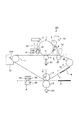
図1は第1実施形態の画像形成装置の構成の説明図である。
<Image forming apparatus>
FIG. 1 is an explanatory diagram of a configuration of the image forming apparatus according to the first embodiment.
図1に示すように、画像形成装置100は、中間転写ベルト7に1個の感光ドラム1を付設したモノクロ画像形成装置である。感光ドラム1に形成されたトナー像は、中間転写ベルト7へ一次転写される。
As shown in FIG. 1, the
感光ドラム1の周囲には、帯電ローラ2、露光装置3、現像装置4、一次転写ローラ5、クリーニング装置6が配置される。
A
感光ドラム1は、外径84mmのアルミニウム製シリンダの外周面に有機感光体(OPC)の感光層を形成されて回転自在に支持され、矢印R1方向に回転する。
The
帯電ローラ2は、電源D3から負極性の直流電圧に交流電圧を重畳した振動電圧を印加されて、感光ドラム1の表面を一様な負極性の電位に帯電させる。
The
露光装置3は、画像データを展開した走査線画像データをON−OFF変調したレーザービームを不図示の回転ミラーで走査して、帯電した感光ドラム1の表面に静電像を書き込む。
The
現像装置4は、磁性トナーを含む一成分現像剤を負極性に帯電させて、固定磁極4Mの周囲で感光ドラム1と微小間隔(300μm)を隔てて回転する現像スリーブ4Sに担持させて、感光ドラム1に供給する。電源D4は、負極性の直流電圧に交流電圧を重畳した振動電圧を現像スリーブ4Sに印加して、感光ドラム1の露光された領域へトナーを付着させて、静電像を反転現像する。
The developing
一次転写ローラ5は、感光ドラム1との間に中間転写ベルト7を挟持して、感光ドラム1と中間転写ベルト7との間に一次転写部(転写部)T1を形成する。電源D1は、正極性の直流電圧(定電圧)を一次転写ローラ5に印加して、一次転写部T1を通過する中間転写ベルト7へ、感光ドラム1に担持された画像のトナー像を一次転写させる。
The
クリーニング装置6は、クリーニングブレード6Bを感光ドラム1に摺擦して、一次転写部T1を通過した感光ドラム1に付着した転写残トナーを除去する。
The
中間転写ベルト7は、一次転写部T1で感光ドラム1から転写されたトナー像Nを担持して二次転写部T2へ搬送する。中間転写ベルト7に担持されたトナー像Nは、二次転写部T2へ給送された記録材Pへ二次転写された後に、定着装置8で加熱加圧を受けて記録材Pの表面に定着される。
The
二次転写ローラ12は、対向ローラ10によって内側から支持された中間転写ベルト7に圧接して、中間転写ベルト7と二次転写ローラ12との間に二次転写部T2を形成する。二次転写ローラ12は、外径12mmの鋼鉄製の芯金に、発泡処理をしたNBR(ニトリルブタジエンゴム)を基材とする弾性層を設けたスポンジローラであって、弾性層を含めた外径を24mmとした。二次転写ローラ12の抵抗値は、弾性層の基材にイオン伝導性の抵抗調整剤を分散することで、23℃・50%Rh環境下で、107.5Ω(2kV印加時)となるように調整した。
The
電源D2は、二次転写ローラ12に正極性の直流電圧(定電圧)を印加して、接地電位に接続された対向ローラ10との間に転写電界を形成して、中間転写ベルト7に担持されたトナー像を記録材Pへ二次転写させる。
The power supply D2 applies a positive DC voltage (constant voltage) to the
ベルトクリーニング装置13は、クリーニングブレード13Bを中間転写ベルト7に摺擦して、二次転写部T2を通過した中間転写ベルト7に付着した転写残トナーを除去する。
The
23℃・50%Rh環境下における感光体ドラム1、現像スリーブ4S、及び一次転写ローラ5の電位は、以下のように設定される。
The potentials of the
帯電ローラ2には、−450Vの直流電圧と900Vp−pの交流電圧とが印加される。これにより、感光体ドラム1の表面は、−450Vの暗部電位VDに帯電され、最大画像濃度の静電潜像を形成するようにレーザー露光を受けた箇所は、−200Vの明部電位VLまで電位が低下する。
A DC voltage of −450 V and an AC voltage of 900 Vp-p are applied to the charging
現像スリーブ4Sには、−300Vの直流電圧Vdcと、9kHzの交流波形と、4.5kHzのブランクとを組み合わせたブランクパルス波形の1.2kVp−pの交流電圧とが印加される。 To the developing sleeve 4S, a DC voltage Vdc of −300 V, an AC waveform of 9 kHz, and an AC voltage of 1.2 kVp-p with a blank pulse waveform obtained by combining a 4.5 kHz blank are applied.
一次転写ローラ5に+400Vの定電圧が印加されるとき、一次転写ローラ5と感光ドラム1の明部電位DLとの電位差(一次転写コントラスト)が600Vになる。
When a constant voltage of +400 V is applied to the
<ベルト部材>
中間転写ベルト7は、駆動ローラ30、対向ローラ10、支持ローラ11、一次転写ローラ5、及び一次転写下流ローラ20に掛け渡して支持され、駆動ローラ30に駆動されて矢印R2方向に回転する。中間転写ベルト7は、駆動ローラ30によって張力を印加されると同時に回転駆動をも受ける。中間転写ベルト7の張力は、駆動ローラ30を支持する不図示のバネによって付与されている。駆動ローラ30の表面には、厚さ1mmのシリコンゴムが巻かれており、中間転写ベルト7との摩擦力を上げることで、スリップを回避している。
<Belt member>
The
中間転写ベルト7は、厚さ85μmのポリイミド樹脂フィルムを基材としており、基材にカーボンブラックを分散して、表面抵抗率を1×10¹²Ω/□、体積抵抗率を1×109.5Ω・cmに調整してある。中間転写ベルト7の周長は、527.5mmとし、回転速度(プロセススピード)を130mm/secとした。
The
中間転写ベルト7は、駆動ローラ30によって張力を印加されており、印加される張力は1.14N/cmである。中間転写ベルト7のヤング率は3.5GPaである。
The
<支持回転体>
一次転写部T1でトナー像を転写された中間転写ベルト7のトナーを担持する反対側の面が、一次転写部T1を通過後、最初に接触する支持回転体は、一次転写下流ローラ20である。そして、一次転写下流ローラ20の次に中間転写ベルト7のトナーを担持する反対側の面が接触する支持回転体は、駆動ローラ30である。一次転写下流ローラ20及び駆動ローラ30の円筒面には、ベルト部材(7)に対する支持回転体の軸方向の連続した接触長さを分断する表面構造を形成してある。
<Support rotating body>
The support rotating body that first contacts the surface of the
一次転写下流ローラ20は、中間転写ベルトを張架して支持する複数の支持回転体のうち、一次転写部T1の直近下流に配設される支持回転体である。一次転写下流ローラ20は、基準濃度トナー像(カラーパッチ)や位置情報トナー像(レジマーク)等を検出する光学式センサ15に対向しており、トナー像の読み取り精度を高めるために必須となる部材である。
The primary transfer
一次転写下流ローラ20は、導電性の材料である外径16mmのステンレス製の円筒管で形成して接地電位に接続されている。一次転写部T1において、一次転写ローラ5から電荷を付与された中間転写ベルト7のトナー像を担持する反対側の面に接触するため、接地していないと、一次転写下流ローラ20がチャージアップすることがある。チャージアップすると、周辺の部材へリークして、画像形成装置100の電子回路に電気的ストレスを与えることがある。
The primary transfer
中間転写ベルト7のトナー像を担持する反対側の面が一次転写下流ローラ20に接触した瞬間に、中間転写ベルト7の表面に担持されたトナー像からトナーが飛び散り、トナー像が乱れることがある。これは、一次転写部T1で一次転写ローラ5から中間転写ベルト7に供給されたトナー担持用の電荷が、接触した一次転写下流ローラ20の母線に沿って急速放電されることに起因している。このため、一次転写下流ローラ20の円筒面に、ベルト部材(7)に対する支持回転体の軸方向の連続した接触長さを減少させる表面構造を形成して、一次転写下流ローラ20に接触する前後における中間転写ベルト7の帯電状態の変化を少なくしている。
At the moment when the opposite surface of the
<トナー像の飛び散り現象>
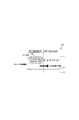
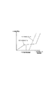
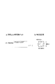
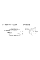
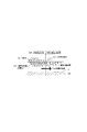
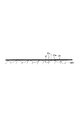
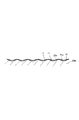
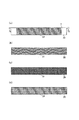
図2は一次転写部を通過した中間転写ベルトの帯電状態の説明図、図3は一次転写ローラ印加電圧と一次転写電流の関係の説明図である。図4はトナー担持用電荷の自然減衰の説明図、図5は一次転写下流ローラ通過時の急速放電の説明図、図6は一次転写下流ローラに接触した中間転写ベルトの帯電状態の説明図である。図4、図5において、(a)は中間転写ベルトの内部の電荷状態、(b)は中間転写ベルトにおける電荷減衰の等価回路図である。
<Toner image scattering phenomenon>
FIG. 2 is an explanatory diagram of the charged state of the intermediate transfer belt that has passed through the primary transfer portion, and FIG. 3 is an explanatory diagram of the relationship between the primary transfer roller applied voltage and the primary transfer current. FIG. 4 is an explanatory diagram of natural decay of the toner carrying charge, FIG. 5 is an explanatory diagram of rapid discharge when passing through the primary transfer downstream roller, and FIG. 6 is an explanatory diagram of the charged state of the intermediate transfer belt in contact with the primary transfer downstream roller. is there. 4 and 5, (a) is a charge state inside the intermediate transfer belt, and (b) is an equivalent circuit diagram of charge attenuation in the intermediate transfer belt.
図2に示すように、一次転写部T1において、一次転写ローラ5から中間転写ベルト7に対して、トナー担持用の電荷が注入され、トナー担持面に移動することで、トナー像Nが中間転写ベルト7に担持される。ここで、図2中の+印は、トナー担持用電荷を模式的に表したものであり、トナー担持用電荷の極性は、マイナス極性に帯電したネガトナーと逆極性のプラスである。そして、トナー担持用電荷の総量は、トナー像Nの総電荷量よりも多いので、一次転写直後の中間転写ベルト7のトナー担持面には、過剰なプラス電荷が存在しており、トナー担持用電荷は、トナーのあるところと、無いところで量が異なる。
As shown in FIG. 2, in the primary transfer portion T1, the toner carrying charge is injected from the
図2を参照して図3に示すように、一次転写を行う際に、トナーのあるところと無いところとでは、一次転写ローラ5から流れ込む電流値が異なる。トナーが無いところでは、感光ドラム1の表層が絶縁層であるため、放電でしか電荷が移動せず、中間転写ベルト7のトナー担持面と感光ドラム1との間で放電が始まる一次転写設定電圧まで、一次転写ローラ5から中間転写ベルト7へ電流が流れない。
As shown in FIG. 3 with reference to FIG. 2, when primary transfer is performed, the value of current flowing from the
一方、トナーのあるところでは、電界を印加すると感光ドラム1から中間転写ベルト7へ帯電したトナーが移動するため、放電が起こらない一次転写設定電圧でも、一次転写ローラ5から中間転写ベルト7へ電流が流れ込む。
On the other hand, when an electric field is applied, the charged toner moves from the
以上の理由から、トナー像Nを中間転写ベルト7へ一次転写した際には、トナーのあるところでは中間転写ベルト7にかなりの電荷が注入されるが、トナーの無いところでは電荷が少ししか注入されない。そして、一次転写部T1を通過した中間転写ベルト7では、トナーのある場所で電荷が多く存在し、トナーの無いところには電荷は少量しか存在せず、電荷量に差が生じている。
For the above reasons, when the toner image N is primarily transferred to the
しかし、実際には、トナーのあるところでは、トナー担持用電荷のうち、トナー像Nの総電荷量と等しい電荷量がトナー像Nの電荷と相殺されるので、マクロには余剰な電荷分しか存在していないように見える。 However, in actuality, in the toner, the charge amount equal to the total charge amount of the toner image N out of the toner carrying charge is offset with the charge of the toner image N, so that the macro has only an excess charge amount. Looks like it doesn't exist.
すなわち、一次転写部T1を通過する過程で、中間転写ベルト7は、トナーのあるところ、無いところともに帯電電荷を注入され、電荷量としてはトナーのあるところの方が多くなる。しかし、トナーのあるところでは、トナー像Nの総電荷量と等しい電荷量の帯電電荷がマクロには相殺されるため、見かけ上は、トナー像Nの総電荷量を越える余剰電荷量のみしか存在していない。このことから、トナーのあるところと無いところとで実効的な電荷量の差は小さく、中間転写ベルト7の内部で、電位差が発生してトナーのあるところからトナーの無いところへ電荷が移動することは少ない。
That is, in the process of passing through the primary transfer portion T1, the
図4に示すように、中間転写ベルト7の内部に分布するトナー担持用電荷は、中間転写ベルト7の回転に伴って緩やかに自然減衰する。電荷を保持した誘電体である中間転写ベルト7は、開放端のRC並列接続回路と等価である。
As shown in FIG. 4, the toner carrying charge distributed inside the
図4の(b)に示すように、等価回路のコンデンサに一定の電荷が保持されている状態では、抵抗の両端に電位差が生じていることから、抵抗を通じて電流が流れ、コンデンサの電荷を放出していく現象が発生する。トナー担持用電荷の自然放電現象は、中間転写ベルト7が一次転写部T1を抜けて、接地電位に接続された支持回転体に接触しないフロート状態で発生する電位減衰である。この電位減衰は、誘電体そのものの伝導特性、誘電特性に依存する現象で、トナーの存在には影響を受けない。
As shown in FIG. 4 (b), when a constant charge is held in the capacitor of the equivalent circuit, a potential difference occurs between both ends of the resistor, so that a current flows through the resistor and discharges the capacitor charge. The phenomenon of doing occurs. The spontaneous discharge phenomenon of the toner carrying charge is potential attenuation that occurs in a float state where the
すなわち、一次転写部T1を抜けて、中間転写ベルト7がフロート状態になると、中間転写ベルト7の内部で電荷の自然減衰が進行するが、このとき、トナーのあるところと無いところとで電位低下の時定数は同じである。このため、一次転写部T1において、トナーのあるところと無いところとで生じさせたトナー担持用電荷の差は維持されるので、トナーのあるところから無いところへトナーが飛散する飛び散りは発生しない。
In other words, when the
図5に示すように、中間転写ベルト7の内部に分布するトナー担持用電荷は、一次転写下流ローラ20との接触に伴って急速に逃散する。接地電位に接続された支持回転体へ中間転写ベルト7からトナー担持用電荷が逃げ出すことによる電位減衰は、トナーの存在に大きく影響を受ける。
As shown in FIG. 5, the toner carrying charge distributed inside the
図5の(b)に示すように、接地電位に接続された一次転写下流ローラ20に中間転写ベルト7の裏面が接触することは、中間転写ベルト7と等価なRC並列接続回路の一端が接地電位に短絡されることと等価である。
As shown in FIG. 5B, when the back surface of the
中間転写ベルト7に担持されたトナーは絶縁性のため、ある電荷を保持したコンデンサCtとみなせる。コンデンサCtの一端は、中間転写ベルト7のRC並列接続回路と直列につながり、他端は電気的にはフロートの状態にある。このようなRC並列接続回路から電荷が接地電位へ流れ出すとき、電位の減衰は、RC並列接続回路に直列につながっているコンデンサCtに蓄積された電荷が多いほど、減衰の時定数が長くなる性質がある。すなわち、接地電位に接続された一次転写下流ローラ20を通過する過程で中間転写ベルト7から一次転写下流ローラ20を通じて電荷が逃げ出すことに起因する電位の減衰は、トナーがあるところの方が、トナーの無いところよりも長くなる。
Since the toner carried on the
すなわち、中間転写ベルト7が回転して一次転写下流ローラ20に接触すると、一次転写下流ローラ20を通じてトナー担持電荷が接地電位に逃げることに起因する電位の減衰が発生する。このとき、トナーがあるところの方が、トナーの無いところよりも電荷が減衰しにくく、電位の減衰の時定数が長くなる。
That is, when the
図6に示すように、このため、中間転写ベルト7の内部には、トナーのあるところからトナーの無いところに向う大きな電界が発生して、トナーのあるところからトナーの無いところへ電荷の一部が移動してしまう。トナーのあるところからトナーの無いところに向う電界は、中間転写ベルト7が一次転写下流ローラ20に接触しているときに最も大きくなる。
For this reason, as shown in FIG. 6, a large electric field is generated in the
これにより、中間転写ベルト7の内部で移動する電荷を追いかけるように、トナー像担持面のトナーのあるところからトナーの無いところへトナーが飛散する。中間転写ベルト7の内部の電荷が失われたトナーのあるところでは、相互に反発するトナー粒子をトナー像担持面に引き止められなくなる。トナー担持用電荷の再配置が発生して、トナーのあるところに存在していたトナー担持用電荷の一部が、トナーの無いところに移動してしまう。これにより、中間転写ベルト7に静電的に保持できなくなったトナー粒子が、トナー同士の電荷の反発によって弾き飛ばされ、再配置されたトナー担持用電荷の分布に応じて移動してトナーの飛び散り現象が発生してしまう。
As a result, the toner scatters from where the toner is present on the toner image carrying surface to where there is no toner so as to follow the charge moving inside the
トナーの飛び散り現象に対して、一次転写下流ローラ20を抵抗を介して接地電位に接続することが提案されている。抵抗を介して接地電位に接続すれば、一次転写下流ローラ20を通過する際の電位の減衰の時定数を長くなって、トナー担持用電荷の減衰量が低減して、再配置が起こりにくくなるからである(図5の(b)参照)。しかし、一次転写下流ローラ20を直接に接地しない場合、構成が複雑化してコストアップにつながるおそれがある。
It has been proposed to connect the primary transfer
<実施例1>
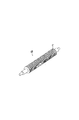
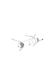
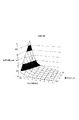
図7は実施例1の一次転写下流ローラの斜視図、図8は一次転写下流ローラの長手方向の部分的な断面図、図9は一次転写下流ローラと中間転写ベルトの接触状態の説明図である。図10は比較例1の一次転写下流ローラの説明図、図11は比較例2の一次転写下流ローラの説明図、図12は中間転写ベルトの張力が過剰な場合の説明図、図13は溝構造における中間転写ベルトのひずみ量の線図である。
<Example 1>
7 is a perspective view of the primary transfer downstream roller in
図7に示すように、実施例1では、一次転写下流ローラ20の表面構造として、螺旋状の溝構造21を設けた。螺旋状の溝構造21は、周方向とほぼ平行であるが、一次転写下流ローラ20の円筒面の接線方向に対してわずかな傾斜を持たせているので、回転に伴って中間転写ベルト7に対する接触位置が移動する。
As shown in FIG. 7, in Example 1, a
図8に示すように、螺旋状の溝構造21の長手方向の断面は、多数の三角溝で構成されており、円筒面の軸方向に隣り合う溝構造21は、それぞれの溝内斜面21eが隣接して稜線22を形成する。溝構造21は、旋盤を用いた切削加工で形成され、溝深さDは30μm、溝ピッチLは200μmである。
As shown in FIG. 8, the longitudinal cross section of the
図9に示すように、実施例1では、螺旋状の溝構造21の稜線22を中間転写ベルト7の内側面に対して線状に接触させることで、中間転写ベルト7に担持されたトナー像の飛び散りを効果的に回避できる。
As shown in FIG. 9, in Example 1, the
溝構造21の谷部は、中間転写ベルト7と接触せず、中間転写ベルト7と一次転写下流ローラ20とが接触する部位は、溝構造21の稜線22のみに限定される。このため、一次転写下流ローラ20が平坦な円筒面で中間転写ベルト7に対して面接触する場合に比較して、中間転写ベルト7と一次転写下流ローラ20の接触面積は大幅に減少している。
The valley portion of the
これにより、中間転写ベルト11が一次転写下流ローラ20に接触した際に、一次転写下流ローラ20を通じて接地電位へ電荷が逃げ出す位置が分断され、通過するまでに逃げ出せる電荷量もごく僅かになる。このため、一次転写下流ローラ20が接地電位に接続されてチャージアップが阻止されているにもかかわらず、一次転写下流ローラ20に接触する前後における中間転写ベルト11の帯電状態の変化が小さくて済む。一次転写下流ローラ20を通過しても、中間転写ベルト7の内部の電荷の挙動は、図4に示す自然減衰の場合に近くなり、中間転写ベルト7の内部でトナー担持電荷の再配置が発生しにくくなって、トナーの飛び散りが抑制される。
As a result, when the
実施例1では、溝加工した支持回転体とベルト部材の接触面積を小さくすることで飛び散りを回避するため、螺旋状の溝構造は、隣接する溝構造の溝内斜面が稜線で連接していることが望ましい。 In Example 1, in order to avoid scattering by reducing the contact area between the grooved support rotating body and the belt member, in the spiral groove structure, the in-groove slopes of adjacent groove structures are connected by ridge lines. It is desirable.
図10に示すように、比較例1の一次転写下流ローラ20Hでは、隣接する溝構造21の溝内斜面21eが連接していない。このため、溝構造21の間の円筒面で中間転写ベルト7と一次転写下流ローラ20とが接触し、接触面積が増えるので、飛び散りを効果的に改善できない。溝構造21の間の円筒面に接する中間転写ベルト7の内部で電荷の再配置が発生して飛び散りが発生する。
As shown in FIG. 10, in the primary transfer
実施例1では、中間転写ベルト7に印加する張力は、0.25N/cm以上3.5N/cm以下の線圧とするのが望ましい。0.25N/cm未満の線圧では、回転駆動を行う際に、駆動ローラ30と中間転写ベルト7との間に十分な摩擦力を確保できず、スリップする可能性がある。
In Example 1, it is desirable that the tension applied to the
図11に示すように、3.5N/cmよりも高い張力を中間転写ベルト7に印加すると、中間転写ベルト7が一次転写下流ローラ20の溝構造21に大きく食い込む。
As shown in FIG. 11, when a tension higher than 3.5 N / cm is applied to the
図12に示すように、過剰な張力を印加した中間転写ベルト7が一次転写下流ローラ20に張架されると、張架部の近傍でベルト面が波打ってしまい、極端に大きな波うちによって画像不良が発生する恐れがある。図1に示す光学式センサ15によるベルト面からの反射光の検知誤差を招く可能性もある。
As shown in FIG. 12, when the
溝構造21の溝内斜面21eに接触するほど撓み量が大きいと、中間転写ベルト7と一次転写下流ローラ20との接触面積が増えて、トナー像の飛び散りが悪化する可能性がある。
If the amount of deflection is large enough to contact the in-groove
実施例1では、中間転写ベルト7に張力を印加して張架する際に、一次転写下流ローラ20表面の溝構造21の存在により、溝部と稜線とで中間転写ベルト7の撓み量を見積もることが可能である。
In the first exemplary embodiment, when the tension is applied to the
図8に示すように、実施例1では、一次転写下流ローラ20に設ける溝構造21は、溝ピッチLが25μm以上400μm以下で、溝深さDが10μm以上50μm以下であることが好ましい。
As shown in FIG. 8, in Example 1, the
溝ピッチLが25μm以下の場合、中間転写ベルト7と一次転写下流ローラ20との接触面積を十分に減らすことができないので、飛び散りを十分に改善できない可能性がある。
When the groove pitch L is 25 μm or less, the contact area between the
図11に示すように、溝ピッチLが400μm以上の場合、溝構造21に撓んだ中間転写ベルト7が極端に侵入するので、図12に示すように、一次転写下流ローラ20Hによる張架部に波うちが発生する可能性がある。
As shown in FIG. 11, when the groove pitch L is 400 μm or more, the
ここで、Lを溝ピッチ[mm]、dを中間転写ベルト7の厚み[mm]、bを中間転写ベルト7の1次転写下流ローラ20へのまきつけ量[mm]とする。また、Pを中間転写ベルトに印加する張力[N]、Eを中間転写ベルトのヤング率[N/mm2]とする。このとき、ひずみ量h[mm]は、両端の回動が拘束された両持ち梁の撓み量として、次式により概算される。
h=1/4×(L3/(d3×b))×(P/E)×106 ・・・(1)
Here, L is the groove pitch [mm], d is the thickness [mm] of the
h = 1/4 × (L3 / (d3 × b)) × (P / E) × 10 6 (1)
図13には、中間転写ベルト7の一次転写下流ローラ20へのまきつけ量bが25mm、溝構造21の溝ピッチが400μmのときの(1)式で求めた中間転写ベルト7のひずみ量が示される。図13によれば、中間転写ベルト7の張力:1.14N/cm、ヤング率:3.5GPaにおける最大ひずみ量、溝部へ向けて中間転写ベルト7が食い込む深さは約3.5μmと概算される。
FIG. 13 shows the amount of distortion of the
実際には、中間転写ベルト7を回転駆動する際にはベルト面内でのヤング率のばらつきや、長手方向での張力のばらつきが発生する。このため、一次転写下流ローラ20の溝深さDは、3.5μmに対して余裕を持つことが望ましく、好適には10μm以上とすることが好ましい。
Actually, when the
一方、溝深さDを50μm以上とすると、中間転写ベルト7に上述の張力を印加した際に、一次転写下流ローラ20の中央部の撓み量が過剰になる可能性がある。金属管ローラ部材である一次転写下流ローラ20の表面に、周方向の溝加工を施したことで、長手方向の曲げ剛性が低下して撓み量が大きくなるからである。このため、溝深さは好適には50μm以下とすることが好ましい。
On the other hand, if the groove depth D is 50 μm or more, when the above-described tension is applied to the
溝構造21の隣り合う稜線のピッチは、停止状態で接するベルト部材が永久変形しない限界幅よりも狭く、溝構造21の深さは、停止状態で支持されたベルト部材が溝面に接触する限界深さよりも深いことが望ましい。
The pitch of the adjacent ridge lines of the
中間転写ベルト7は、ヤング率が3.5GPaのベルト材料を使用しているが、ベルト材料のヤング率としては、0.5GPa以上であることが望ましい。ヤング率が0.5GPa以下のやわらかいベルト材料を用いると、一次転写下流ローラ20による張架部で、図11に示すように、中間転写ベルト7が一次転写下流ローラ20の溝構造21に食い込む可能性がある。中間転写ベルト7と一次転写下流ローラ20との接触面積が増えて、飛び散りが悪化する可能性がある。
The
実施例1では、ベルト材料の基材としてポリイミド樹脂を使用したが、ポリカーボネート、ポリエチレンテレフタラート、ナイロン、ポリアミドなど、他の樹脂でも好適に使用できる。 In Example 1, a polyimide resin was used as the base material of the belt material, but other resins such as polycarbonate, polyethylene terephthalate, nylon, and polyamide can also be suitably used.
<実施例2>
図14は実施例2の一次転写下流ローラの溝構造の説明図である。実施例2は、図1に示す画像形成装置100の一次転写下流ローラ20の円筒面の溝構造のみを実施例1と異ならせている。
<Example 2>
FIG. 14 is an explanatory diagram of the groove structure of the primary transfer downstream roller according to the second embodiment. The second embodiment differs from the first embodiment only in the groove structure on the cylindrical surface of the primary transfer
実施例1では、図8に示すように、一次転写下流ローラ20表面に形成された螺旋状の溝構造21は、断面が三角形に形成されたが、図14に示すように、実施例2では、溝構造21Aの断面が楕円形状である。
In the first embodiment, as shown in FIG. 8, the
一次転写下流ローラ20表面に形成される螺旋状の溝構造21Aが楕円溝であっても、隣接する楕円溝の稜線22Aを中間転写ベルト7の内側面に対して線状に接触させることで、トナー像の飛び散りを効果的に回避できる。
Even if the
<実施例3>
図15は実施例3の一次転写下流ローラの溝構造の説明図である。実施例3は、図1に示す画像形成装置100の一次転写下流ローラ20の円筒面の溝構造のみを実施例1と異ならせている。
<Example 3>
FIG. 15 is an explanatory diagram of the groove structure of the primary transfer downstream roller according to the third embodiment. The third embodiment is different from the first embodiment only in the groove structure of the cylindrical surface of the primary transfer
実施例1では、図8に示すように、一次転写下流ローラ20表面に形成された螺旋状の溝構造21は、断面が三角形に形成されたが、図15に示すように、実施例3では、溝構造21Bの断面が逆台形である。
In Example 1, as shown in FIG. 8, the
一次転写下流ローラ20表面に形成される螺旋状の溝構造21Bが逆台形溝であっても、隣接する逆台形溝の稜線22Bを中間転写ベルト7の内側面に対して線状に接触させることで、トナー像の飛び散りを効果的に回避できる。
Even if the
実施例1において、一次転写下流ローラ20表面の、螺旋状の溝を設ける際に三角溝を設けたが、図15に示すような、逆台形溝を設けても、好適に使用できる。
In Example 1, the triangular groove is provided when the spiral groove on the surface of the primary transfer
<実施例4>
図1に示すように、実施例4では、画像形成装置100の一次転写下流ローラ20とともに、その下流に位置する駆動ローラ30の円筒面にも溝構造を形成した。
<Example 4>
As shown in FIG. 1, in Example 4, a groove structure was formed on the cylindrical surface of the
一次転写部T1でトナー像を転写された中間転写ベルト7が、一次転写部T1を通過後、最初に接触する支持回転体は、一次転写下流ローラ20である。そして、一次転写下流ローラ20の次に中間転写ベルト7へ接触する支持回転体は、駆動ローラ30である。一次転写下流ローラ20及び駆動ローラ30の円筒面には、ベルト部材(7)に対する支持回転体の軸方向の連続した接触長さを減少させた表面構造を形成してある。
The support rotating body that first contacts the
駆動ローラ30の円筒面には厚さ1.5mmのゴム弾性層が形成されて全体の外径は38mmであって、ゴム弾性層を切り込んで、図7、図8に示されるような螺旋状の三角溝を形成している。溝ピッチLは500μm、溝深さDは500μmである。
A rubber elastic layer having a thickness of 1.5 mm is formed on the cylindrical surface of the
<実施例5>
図16は実施例5の一次転写下流ローラの溝構造の説明図である。実施例5は、図1に示す画像形成装置100の一次転写下流ローラ20の円筒面の溝構造の軸方向の配置を実施例1と異ならせている。
<Example 5>
FIG. 16 is an explanatory diagram of the groove structure of the primary transfer downstream roller according to the fifth embodiment. The fifth embodiment is different from the first embodiment in the axial arrangement of the groove structure of the cylindrical surface of the primary transfer
図16の(a)に示すように、螺旋状の溝構造21は、中間転写ベルト7の最大画像形成幅の領域にのみ形成し、最大画像形成幅の外側は、溝構造の無い平坦な円筒面で残してもよい。中間転写ベルト7の両端には、軸方向への移動を限界付けるための寄り止めガイド部7gを貼付してある。
As shown in FIG. 16A, the
図16の(b)に示すように、溝構造21は、それぞれが独立して閉じる複数の平行溝で形成してもよい。また、一次転写下流ローラ20の接線方向に対する傾きが異なる2種類の溝構造21を交互に配置してもよい。
As shown in FIG. 16B, the
図16の(c)に示すように、溝構造21は、一次転写下流ローラ20の接線方向に対する傾きが異なる2種類の溝構造を交差して形成してもよい。このような溝構造は、切削加工によらず転写加工(いわゆるローレット加工)によって形成してもよい。
As shown in FIG. 16C, the
図16の(d)に示すように、溝構造は、円筒面の一周に渡って連続している必要は無く、周方向に断続した多数の溝で形成してもよい。 As shown in FIG. 16 (d), the groove structure does not need to be continuous over one round of the cylindrical surface, and may be formed by a number of grooves intermittent in the circumferential direction.
(a)〜(d)いずれの溝パターンでも、実施例1と同様に、軸方向の断面では、溝構造21の隣り合う稜線のピッチは、停止状態で接するベルト部材が永久変形しない限界幅よりも狭い。溝構造21の深さは、停止状態で支持されたベルト部材が溝面に接触する限界深さよりも深い。
In any of the groove patterns (a) to (d), as in the first embodiment, in the axial section, the pitch of the adjacent ridge lines of the
<実施例6>
図17は実施例6の画像形成装置の構成の説明図である。実施例7は、複数の感光ドラムを中間転写ベルトに配置したタンデム型画像形成装置の張架ローラ及び駆動ローラの円筒面に溝構造を形成している。
<Example 6>
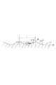
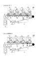
FIG. 17 is an explanatory diagram of a configuration of the image forming apparatus according to the sixth embodiment. In the seventh embodiment, a groove structure is formed on the cylindrical surface of the stretching roller and the driving roller of the tandem type image forming apparatus in which a plurality of photosensitive drums are arranged on the intermediate transfer belt.
図17の(a)に示すように、画像形成装置200は、中間転写ベルト7に沿ってイエロー、マゼンダ、シアン、ブラックの画像形成部Pa、Pb、Pc、Pdを配置した電子写真方式のフルカラーレーザープリンタである。画像形成部Pa、Pb、Pc、Pdは、現像装置4a、4b、4c、4dで用いるトナーの色がイエロー、マゼンダ、シアン、ブラックと異なる以外は同様に構成される。そして、画像形成部Pa、Pb、Pc、Pdに配置された各構成には、図1に示される対応する構成の参照符号に、画像形成部Pa、Pb、Pc、Pdの区別を表すa、b、c、dを付加した参照符号を付している。
As shown in FIG. 17A, the
イエローの画像形成部Paでは、感光ドラム1aは、外径84mmのアルミニウム製のシリンダに、有機感光体(OPC)を塗布して構成したものである。感光ドラム1aは、帯電ローラ2aによって表面を一様に帯電された後、露光装置3aによるレーザビームの走査露光を受け、イエロー画像の静電像を形成される。
In the yellow image forming portion Pa, the photosensitive drum 1a is configured by applying an organic photoreceptor (OPC) to an aluminum cylinder having an outer diameter of 84 mm. After the surface of the photosensitive drum 1a is uniformly charged by the charging roller 2a, the photosensitive drum 1a is subjected to scanning exposure with a laser beam by the
現像装置4aは、二成分現像剤を攪拌して帯電させ、現像スリーブに担持させて感光ドラム1aの静電像にイエロートナーを供給することにより、イエロートナー像を現像する。感光ドラム1aに形成されたイエロートナー像は、一次転写ローラ5aによって、中間転写ベルト7上に一次転写さる。そして、イエロートナー像を中間転写ベルト7に転移した感光ドラム1aは、クリーニング装置6aによって表面を清掃されて次回以降の画像形成動作に供される。
The developing device 4a stirs and charges the two-component developer, carries the developer on the developing sleeve, and supplies the yellow toner to the electrostatic image on the photosensitive drum 1a, thereby developing the yellow toner image. The yellow toner image formed on the photosensitive drum 1a is primarily transferred onto the
マゼンダ、シアン、ブラック各色成分のトナー像は、上記と同様のプロセスで形成されて中間転写ベルト7上に重ねて一次転写される。中間転写ベルト7上に形成された4色のトナー像は、対向ローラ10及び二次転写ローラ12から構成される二次転写部T2へ搬送され、所定のタイミングで給送された記録材Pへ一括二次転写される。
The magenta, cyan, and black color component toner images are formed by the same process as described above and are primarily transferred onto the
トナー像を二次転写された記録材Pは、定着装置8によって加熱加圧定着を受けて永久画像となる。トナー像を記録材へ二次転写した後、中間転写ベルト7は、ベルトクリーニング装置13によって清掃を受けて、次回以降の画像形成に供される。
The recording material P onto which the toner image has been secondarily transferred undergoes heat and pressure fixing by the fixing
図17の(b)に示すように、画像形成装置200は、ブラックの画像形成部Pdを用いてモノクロ画像を形成するブラック単色モードでは、画像形成部Pa、Pb、Pcから中間転写ベルト7から離間させる。
As shown in FIG. 17B, in the black monochrome mode in which a black and white image is formed using the black image forming portion Pd, the
張架ローラ20よりも上流側で中間転写ベルト7を支持するテンションローラ11及び一次転写ローラ5a、5b、5cを下方へ移動して、感光ドラム1a、1b、1cと中間転写ベルト7との接触を解除する。
The
図17の(a)に示すように、フルカラーモードでは、接地電位に接続された張架ローラ20の円筒面が中間転写ベルト7の内側面に常時接触している。このため、画像形成部Pa、Pb、Pcでトナー像を一次転写された中間転写ベルト7が張架ローラ20を通過する際に、トナー像が飛び散りを発生する可能性がある。
As shown in FIG. 17A, in the full color mode, the cylindrical surface of the stretching
そこで、実施例6では、張架ローラ20の円筒面に、図7、図8に示されるような螺旋状の三角溝の溝構造21を形成した。実施例4と同様に、張架ローラ20の下流に位置する駆動ローラ30の円筒面にも溝構造を形成した。
Therefore, in Example 6, a spiral
以上説明したように、中間転写ベルトの張架部材の表層に螺旋状の溝構造を設けることで、中間転写ベルトから張架部材へトナー担持電荷が減衰することを抑制して、トナー像の飛び散りを有効に回避できる。 As described above, by providing a spiral groove structure on the surface layer of the tension member of the intermediate transfer belt, it is possible to suppress the toner-carrying charge from being attenuated from the intermediate transfer belt to the tension member, and to scatter the toner image. Can be effectively avoided.
従って、安定して飛び散りの発生しない、高画質を維持することのできる画像形成装置を提供できる。 Therefore, it is possible to provide an image forming apparatus capable of maintaining high image quality without causing stable scattering.
1 像担持体(感光ドラム)
2 帯電ローラ
3 露光装置
4 現像装置
5 一次転写ローラ
6 クリーニング装置
7 ベルト部材(中間転写ベルト)
10 対向ローラ
12 二次転写ローラ
20 支持回転体(一次転写下流ローラ)
21 溝構造
21e 溝内斜面
22 稜線
30 駆動ローラ
1 Image carrier (photosensitive drum)
2 Charging
10
21
Claims (4)
転写部で前記像担持体から転写されたトナー像を担持して移動するベルト部材と、を備えた画像形成装置において、
接地電位に接続された導電性の円筒面がトナー像を担持した反対側の面に接するように前記ベルト部材を支持する支持回転体を備え、
前記支持回転体は、前記ベルト部材に対する前記円筒面の軸方向の連続した接触長さが分断される表面構造を有することを特徴とする画像形成装置。 An image carrier on which a toner image is formed;
A belt member that carries and moves the toner image transferred from the image carrier in the transfer unit, and an image forming apparatus comprising:
A support rotating body that supports the belt member so that a conductive cylindrical surface connected to a ground potential is in contact with an opposite surface carrying a toner image;
The image forming apparatus according to claim 1, wherein the support rotating body has a surface structure in which a continuous contact length in the axial direction of the cylindrical surface with respect to the belt member is divided.
前記溝構造の深さは、停止状態で支持された前記ベルト部材が溝面に接触する限界深さよりも深いことを特徴とする請求項3記載の画像形成装置。 The pitch of the adjacent ridgelines of the groove structure is narrower than the limit width at which the belt member in contact in the stopped state is not permanently deformed,
The image forming apparatus according to claim 3, wherein a depth of the groove structure is deeper than a limit depth at which the belt member supported in a stopped state contacts the groove surface.
Priority Applications (1)
| Application Number | Priority Date | Filing Date | Title |
|---|---|---|---|
| JP2008179321A JP5317559B2 (en) | 2008-07-09 | 2008-07-09 | Image forming apparatus |
Applications Claiming Priority (1)
| Application Number | Priority Date | Filing Date | Title |
|---|---|---|---|
| JP2008179321A JP5317559B2 (en) | 2008-07-09 | 2008-07-09 | Image forming apparatus |
Publications (2)
| Publication Number | Publication Date |
|---|---|
| JP2010020006A true JP2010020006A (en) | 2010-01-28 |
| JP5317559B2 JP5317559B2 (en) | 2013-10-16 |
Family
ID=41704990
Family Applications (1)
| Application Number | Title | Priority Date | Filing Date |
|---|---|---|---|
| JP2008179321A Active JP5317559B2 (en) | 2008-07-09 | 2008-07-09 | Image forming apparatus |
Country Status (1)
| Country | Link |
|---|---|
| JP (1) | JP5317559B2 (en) |
Cited By (2)
| Publication number | Priority date | Publication date | Assignee | Title |
|---|---|---|---|---|
| KR20180111637A (en) * | 2017-03-30 | 2018-10-11 | 캐논 가부시끼가이샤 | Image forming apparatus |
| WO2019107351A1 (en) * | 2017-11-28 | 2019-06-06 | キヤノン株式会社 | Image forming device |
Citations (8)
| Publication number | Priority date | Publication date | Assignee | Title |
|---|---|---|---|---|
| JPH08234602A (en) * | 1995-02-28 | 1996-09-13 | Canon Inc | Fixing device and image forming device |
| JPH09329975A (en) * | 1996-06-13 | 1997-12-22 | Fuji Xerox Co Ltd | Image forming device |
| JP2000298408A (en) * | 1999-02-08 | 2000-10-24 | Fuji Xerox Co Ltd | Image forming device |
| JP2001331014A (en) * | 2000-05-19 | 2001-11-30 | Canon Inc | Image forming device |
| JP2004317915A (en) * | 2003-04-18 | 2004-11-11 | Canon Inc | Image forming apparatus |
| JP2005316205A (en) * | 2004-04-28 | 2005-11-10 | Canon Inc | Image forming apparatus |
| JP2007003575A (en) * | 2005-06-21 | 2007-01-11 | Ricoh Co Ltd | Static eliminator device and image forming apparatus using same |
| JP2009157068A (en) * | 2007-12-26 | 2009-07-16 | Fuji Xerox Co Ltd | Belt transfer device and image forming apparatus using the same |
-
2008
- 2008-07-09 JP JP2008179321A patent/JP5317559B2/en active Active
Patent Citations (8)
| Publication number | Priority date | Publication date | Assignee | Title |
|---|---|---|---|---|
| JPH08234602A (en) * | 1995-02-28 | 1996-09-13 | Canon Inc | Fixing device and image forming device |
| JPH09329975A (en) * | 1996-06-13 | 1997-12-22 | Fuji Xerox Co Ltd | Image forming device |
| JP2000298408A (en) * | 1999-02-08 | 2000-10-24 | Fuji Xerox Co Ltd | Image forming device |
| JP2001331014A (en) * | 2000-05-19 | 2001-11-30 | Canon Inc | Image forming device |
| JP2004317915A (en) * | 2003-04-18 | 2004-11-11 | Canon Inc | Image forming apparatus |
| JP2005316205A (en) * | 2004-04-28 | 2005-11-10 | Canon Inc | Image forming apparatus |
| JP2007003575A (en) * | 2005-06-21 | 2007-01-11 | Ricoh Co Ltd | Static eliminator device and image forming apparatus using same |
| JP2009157068A (en) * | 2007-12-26 | 2009-07-16 | Fuji Xerox Co Ltd | Belt transfer device and image forming apparatus using the same |
Cited By (9)
| Publication number | Priority date | Publication date | Assignee | Title |
|---|---|---|---|---|
| KR20180111637A (en) * | 2017-03-30 | 2018-10-11 | 캐논 가부시끼가이샤 | Image forming apparatus |
| CN108693747A (en) * | 2017-03-30 | 2018-10-23 | 佳能株式会社 | Imaging device |
| JP2018169578A (en) * | 2017-03-30 | 2018-11-01 | キヤノン株式会社 | Image forming device |
| US10698346B2 (en) | 2017-03-30 | 2020-06-30 | Canon Kabushiki Kaisha | Image forming apparatus |
| KR102224449B1 (en) * | 2017-03-30 | 2021-03-08 | 캐논 가부시끼가이샤 | Image forming apparatus |
| CN108693747B (en) * | 2017-03-30 | 2022-03-04 | 佳能株式会社 | Image forming apparatus |
| WO2019107351A1 (en) * | 2017-11-28 | 2019-06-06 | キヤノン株式会社 | Image forming device |
| JP2019101060A (en) * | 2017-11-28 | 2019-06-24 | キヤノン株式会社 | Image forming apparatus |
| US11086254B2 (en) | 2017-11-28 | 2021-08-10 | Canon Kabushiki Kaisha | Image forming apparatus using developer containing toner particle and carrier liquid |
Also Published As
| Publication number | Publication date |
|---|---|
| JP5317559B2 (en) | 2013-10-16 |
Similar Documents
| Publication | Publication Date | Title |
|---|---|---|
| JP2019003058A (en) | Image forming apparatus and cartridge | |
| JP2002055512A (en) | Electrostatic charging device, and image forming device provided with same | |
| JP2002333762A (en) | Electrifying device and image forming device | |
| JP6278270B2 (en) | Image forming apparatus | |
| JP2008070811A (en) | Charging device and image forming apparatus | |
| JP5317559B2 (en) | Image forming apparatus | |
| JP4690815B2 (en) | Image forming apparatus | |
| JP5574220B2 (en) | Cleaning device, belt device, and image forming apparatus | |
| JP2007079286A (en) | Image forming apparatus and process cartridge to be used for the same | |
| JP6961375B2 (en) | Image forming device | |
| JP2011107532A (en) | Charging device and image forming apparatus | |
| JP2006350028A (en) | Image forming apparatus | |
| JP2000284616A (en) | Image forming device | |
| JP4147835B2 (en) | Contact charger and image forming apparatus | |
| JP3759835B2 (en) | Image forming apparatus | |
| JPH11218999A (en) | Electrifying device | |
| JP3198081B2 (en) | Transfer method and image forming apparatus | |
| JP2005316205A (en) | Image forming apparatus | |
| JP2005004065A (en) | Cleaning device, image forming apparatus, processing unit, cleaning method and image forming method | |
| JP2002251076A (en) | Image forming device | |
| JP5442462B2 (en) | Developing device and image forming apparatus having the same | |
| JPH0980922A (en) | Image forming device | |
| JP2002278226A (en) | Image forming device | |
| JP2008310059A (en) | Image forming device | |
| JP2007147778A (en) | Conductive member, process cartridge, and image forming apparatus |
Legal Events
| Date | Code | Title | Description |
|---|---|---|---|
| A621 | Written request for application examination |
Free format text: JAPANESE INTERMEDIATE CODE: A621 Effective date: 20110707 |
|
| RD05 | Notification of revocation of power of attorney |
Free format text: JAPANESE INTERMEDIATE CODE: A7425 Effective date: 20120125 |
|
| RD03 | Notification of appointment of power of attorney |
Free format text: JAPANESE INTERMEDIATE CODE: A7423 Effective date: 20120203 |
|
| A131 | Notification of reasons for refusal |
Free format text: JAPANESE INTERMEDIATE CODE: A131 Effective date: 20121218 |
|
| A977 | Report on retrieval |
Free format text: JAPANESE INTERMEDIATE CODE: A971007 Effective date: 20121219 |
|
| A521 | Written amendment |
Free format text: JAPANESE INTERMEDIATE CODE: A523 Effective date: 20130214 |
|
| RD04 | Notification of resignation of power of attorney |
Free format text: JAPANESE INTERMEDIATE CODE: A7424 Effective date: 20130228 |
|
| A131 | Notification of reasons for refusal |
Free format text: JAPANESE INTERMEDIATE CODE: A131 Effective date: 20130312 |
|
| A521 | Written amendment |
Free format text: JAPANESE INTERMEDIATE CODE: A523 Effective date: 20130510 |
|
| TRDD | Decision of grant or rejection written | ||
| A01 | Written decision to grant a patent or to grant a registration (utility model) |
Free format text: JAPANESE INTERMEDIATE CODE: A01 Effective date: 20130611 |
|
| A61 | First payment of annual fees (during grant procedure) |
Free format text: JAPANESE INTERMEDIATE CODE: A61 Effective date: 20130709 |
|
| R151 | Written notification of patent or utility model registration |
Ref document number: 5317559 Country of ref document: JP Free format text: JAPANESE INTERMEDIATE CODE: R151 |