JP2010019053A - Door closer - Google Patents
Door closer Download PDFInfo
- Publication number
- JP2010019053A JP2010019053A JP2008183083A JP2008183083A JP2010019053A JP 2010019053 A JP2010019053 A JP 2010019053A JP 2008183083 A JP2008183083 A JP 2008183083A JP 2008183083 A JP2008183083 A JP 2008183083A JP 2010019053 A JP2010019053 A JP 2010019053A
- Authority
- JP
- Japan
- Prior art keywords
- pressure chamber
- door
- high pressure
- closing
- opening
- Prior art date
- Legal status (The legal status is an assumption and is not a legal conclusion. Google has not performed a legal analysis and makes no representation as to the accuracy of the status listed.)
- Granted
Links
- 239000010720 hydraulic oil Substances 0.000 claims description 52
- 238000003780 insertion Methods 0.000 claims description 28
- 230000037431 insertion Effects 0.000 claims description 28
- 230000007246 mechanism Effects 0.000 claims description 27
- 230000000903 blocking effect Effects 0.000 claims description 2
- 239000012530 fluid Substances 0.000 abstract description 4
- 230000008859 change Effects 0.000 description 5
- 238000010586 diagram Methods 0.000 description 3
- 239000003921 oil Substances 0.000 description 3
- 230000002265 prevention Effects 0.000 description 3
- 238000007789 sealing Methods 0.000 description 3
- 230000008901 benefit Effects 0.000 description 1
- 238000007599 discharging Methods 0.000 description 1
- 230000006872 improvement Effects 0.000 description 1
- 230000009467 reduction Effects 0.000 description 1
- 230000000630 rising effect Effects 0.000 description 1
Images


Landscapes
- Closing And Opening Devices For Wings, And Checks For Wings (AREA)
Abstract
Description
この発明は、開いたドアをゆっくりと自動的に閉めるドアクローザ(ドア自閉装置)の改良に関するものである。 The present invention relates to an improvement in a door closer (door self-closing device) that automatically and slowly closes an open door.
一般に、ドアクローザは、作動油が充填された密閉空間を有するハウジングを備え、該ハウジングの密閉空間には、コイルスプリングにより付勢されたピストンが往復移動可能に配置され、該ピストンにより上記密閉空間を高圧室と低圧室とに区画するとともに、これら高圧室と低圧室とを連通・遮断するチェック弁が上記ピストンに設けられている。また、上記ピストンにはラック・ピニオン機構が組み付けられ、該ラック・ピニオン機構のピニオンには、回転軸が上記ハウジングを上下に貫挿するように回転一体に連結されている。さらに、この回転軸の上端には、リンク機構の一端が連結され、該リンク機構の他端は建物のドア開口部の上枠側に連結されている。 Generally, a door closer includes a housing having a sealed space filled with hydraulic oil, and a piston urged by a coil spring is disposed in the sealed space of the housing so as to be able to reciprocate. The piston is provided with a check valve that divides the high pressure chamber and the low pressure chamber and communicates and blocks the high pressure chamber and the low pressure chamber. Further, a rack and pinion mechanism is assembled to the piston, and a rotating shaft is coupled to the pinion of the rack and pinion mechanism so as to rotate integrally therewith so as to penetrate the housing vertically. Further, one end of the link mechanism is connected to the upper end of the rotating shaft, and the other end of the link mechanism is connected to the upper frame side of the door opening of the building.
そして、ドアを開操作すると、その回転動作が上記リンク機構を介して回転軸に伝達され、さらに上記ラック・ピニオン機構を介してピストンの直線動作に変換される。これにより、上記ピストンがハウジングの密閉空間を移動することでコイルスプリングを圧縮し、作動油が低圧室からチェック弁を経て高圧室に流出して、ドアクローザにドアの閉方向に移動する力が蓄積されながらドアが開かれる。ドアから手を離すと、上記圧縮されたコイルスプリングの反発力によりピストンが上記とは逆方向に直線移動し、この際、高圧室と低圧室とはチェック弁で閉じられて高圧室の作動油はチェック弁を経て低圧室には流出しないが、速度調整弁を経て低圧室に流出し、ドアがゆっくりと自動的に閉まるようになっている。このドアの閉速度は、高圧室から低圧室へと流出する作動油の流量を速度調整弁で制御することで調整される。 When the door is opened, the rotational operation is transmitted to the rotary shaft through the link mechanism, and further converted into a linear motion of the piston through the rack and pinion mechanism. As a result, the piston moves in the sealed space of the housing to compress the coil spring, and hydraulic oil flows from the low pressure chamber to the high pressure chamber through the check valve, and the force that moves in the door closing direction is accumulated in the door closer. The door is opened while being done. When the hand is released from the door, the piston moves linearly in the opposite direction due to the repulsive force of the compressed coil spring. At this time, the high pressure chamber and the low pressure chamber are closed by a check valve, and the hydraulic oil in the high pressure chamber is closed. Does not flow into the low-pressure chamber through the check valve, but flows out into the low-pressure chamber through the speed adjustment valve, so that the door slowly and automatically closes. The closing speed of the door is adjusted by controlling the flow rate of the hydraulic oil flowing out from the high pressure chamber to the low pressure chamber with a speed adjustment valve.
ところで、このようなドアクローザを備えたドアがドアクローザの働きでゆっくりと自動的に閉じている途中で強制的に閉じる等して閉方向の外力がドアに作用すると、高圧室から低圧室に流出する作動油の流量は速度調整弁で制御されていて一定であるため、高圧室の内圧が過度に高まってドアクローザの抵抗が増大し、ドアのヒンジやドア開口部の枠部材に無理な力が掛かってこれらが破損するおそれがある。 By the way, when an external force in the closing direction acts on the door by forcibly closing the door equipped with such a door closer while it is automatically closed slowly by the door closer, it flows out from the high pressure chamber to the low pressure chamber. Since the flow rate of the hydraulic fluid is controlled by the speed control valve and is constant, the internal pressure of the high pressure chamber increases excessively, the resistance of the door closer increases, and an unreasonable force is applied to the door hinges and the frame member of the door opening. These may be damaged.
このような破損を防止するために、特許文献1では、ハウジングの壁内にリリーフ弁を設け、圧力が高まった作動油をリリーフ弁を介して低圧室に排出して高圧室の内圧を低減し、これにより、ドアクローザの抵抗が増大しないようにしてドアのヒンジやドア開口部の枠部材に無理な力が掛からないようにし、これらの破損を防止するようにしている。
しかし、上記の特許文献1のようにリリーフ弁を設けてドアクローザの抵抗を増大しないようにしても、ドアの種類や適用場所等使い勝手によっては、リリーフ弁の機能が不要な場合もある。さりとて、ドアの仕様をリリーフ弁があるタイプとないタイプの2通り設けるのは不経済である。
However, even if a relief valve is provided as in
また、上記の特許文献1では、高圧室の作動油を低圧室に排出する別ルートを設けただけであって作動油のリリーフ弁から排出される流量は一定であるため、ドアのサイズや閉方向に作用する外力の程度に応じてドアクローザの抵抗を調整することができず、ドアのヒンジやドア開口部の枠部材に無理な力が掛かることが懸念され、これらの破損対策は万全ではない。
Further, in the above-mentioned
この発明はかかる点に鑑みてなされたものであり、その目的とするところは、リリーフ弁を選択的に切換え可能にすることを第1の目的とし、ドアのサイズや閉方向に作用する外力の程度に応じてドアクローザの抵抗を調整できるようにすることを第2の目的とする。 The present invention has been made in view of such a point, and the object of the present invention is to make it possible to selectively switch the relief valve, and to reduce the size of the door and the external force acting in the closing direction. A second object is to make it possible to adjust the resistance of the door closer according to the degree.
上記の目的を達成するため、この発明は、リリーフ弁を開閉作動可能な状態と開作動不能な状態とに切換え式にしたことを第1の特徴とし、高圧室から低圧室に排出される作動油の排出タイミングを変えるようにしたことを第2の特徴とする。 In order to achieve the above object, the present invention has a first feature that the relief valve is switched between a state in which the relief valve can be opened and closed and a state in which the relief valve cannot be opened. The second feature is that the oil discharge timing is changed.
具体的には、この発明は、作動油が充填された密閉空間を有するハウジングと、上記密閉空間にピストン付勢手段により付勢された状態で往復移動可能に配置され、密閉空間を高圧室と低圧室とに区画するピストンと、該ピストンに設けられ、上記高圧室と低圧室とを連通・遮断するチェック弁と、上記ピストンに組み込まれたラック・ピニオン機構と、該ラック・ピニオン機構のピニオンに上記ハウジングを上下に貫挿するように回転一体に連結された回転軸と、一端が上記回転軸の上端に連結されるとともに、他端が建物のドア開口部の上枠側に連結されたリンク機構と、上記ハウジングに挿着され、上記ピストンの移動に連動して上記高圧室から低圧室に流出する作動油の流量を制御することでドアの閉速度を調整する速度調整弁とを備え、ドアの開操作によりその回転動作を上記リンク機構、回転軸及びラック・ピニオン機構を介してピストンの直線動作に変換して該ピストンを上記ピストン付勢手段の付勢力に抗してハウジングの密閉空間で低圧室縮小方向に移動させ、作動油を低圧室から上記チェック弁を経て高圧室に流出させてドアの閉方向に移動する力を蓄積し、ドアから手を離すことにより上記ピストンを上記ピストン付勢手段の付勢力によりハウジングの密閉空間で高圧室縮小方向に移動させ、高圧室の作動油を上記速度調整弁を経て低圧室に流出させてドアをゆっくりと自動的に閉めるように構成されているドアクローザを対象とし、次のような解決手段を講じた。 Specifically, the present invention includes a housing having a sealed space filled with hydraulic oil, and a reciprocating movement arranged in a state of being urged by a piston urging means in the sealed space. A piston partitioned into a low-pressure chamber; a check valve provided in the piston for communicating and blocking the high-pressure chamber and the low-pressure chamber; a rack and pinion mechanism incorporated in the piston; and a pinion of the rack and pinion mechanism A rotary shaft connected integrally with the housing so as to penetrate the housing up and down, one end connected to the upper end of the rotary shaft, and the other end connected to the upper frame side of the door opening of the building A link mechanism, and a speed adjustment valve that is attached to the housing and adjusts the closing speed of the door by controlling the flow rate of hydraulic oil flowing from the high pressure chamber to the low pressure chamber in conjunction with the movement of the piston. The opening operation of the door is converted into a linear movement of the piston through the link mechanism, the rotation shaft and the rack and pinion mechanism, and the piston is resisted against the biasing force of the piston biasing means. Move the hydraulic oil in the closed space in the shrinking direction of the low-pressure chamber, drain the hydraulic oil from the low-pressure chamber to the high-pressure chamber through the check valve, accumulate the force to move in the closing direction of the door, and release the hand from the door to release the piston. By moving the high pressure chamber in the sealed space of the housing in the sealed space of the housing by the biasing force of the piston biasing means, the hydraulic oil in the high pressure chamber flows out to the low pressure chamber via the speed control valve, and the door is closed slowly and automatically. The following measures were taken for the configured door closer.
すなわち、請求項1に記載の発明は、上記ハウジングには、平時は、上記高圧室と低圧室とを遮断する一方、ドアが閉じている途中で閉方向の外力がドアに作用した際には、上記高圧室と低圧室とを連通して高圧室の作動油を低圧室に排出するリリーフ弁が、開閉作動可能な状態と、開作動不能な状態とに切換え可能に設けられていることを特徴とする。 That is, according to the first aspect of the present invention, when the door is closed, the high pressure chamber and the low pressure chamber are shut off during normal times, and when an external force in the closing direction acts on the door while the door is closed. The relief valve that communicates the high-pressure chamber and the low-pressure chamber and discharges the hydraulic oil in the high-pressure chamber to the low-pressure chamber is provided so as to be switchable between a state that can be opened and closed and a state that cannot be opened. Features.
請求項2に記載の発明は、請求項1に記載の発明において、上記ハウジングには、挿着孔が上記高圧室と低圧室とを連絡するように形成され、該挿着孔には、上記リリーフ弁が外部からの進退操作により位置調整可能に挿着され、該リリーフ弁は、開閉作動可能な状態で、位置を調整することで開閉作動タイミングを高圧室の内圧に応じて自在に変更できるように構成されていることを特徴とする。
The invention according to
請求項3に記載の発明は、請求項2に記載の発明において、上記リリーフ弁は、連絡路が先端に開口するように形成されかつ進退操作により位置調整可能な軸状の弁本体と、上記連絡路を開閉する開閉手段と、該開閉手段を付勢する開閉付勢手段とを備え、開閉作動可能な状態では、平時は、上記開閉手段を開閉付勢手段の付勢力により弁本体先端に押し付けて連絡路を閉じ、上記高圧室と低圧室とを遮断する一方、ドアが閉じている途中で閉方向の外力がドアに作用した際には、上記開閉手段を高圧室の内圧で開閉付勢手段の付勢力に抗して弁本体先端から離れさせて連絡路を開け、上記高圧室と低圧室とを連通して高圧室の作動油を低圧室に排出するように構成されていることを特徴とする。
The invention according to
請求項4に記載の発明は、請求項3に記載の発明において、上記リリーフ弁は、開作動不能な状態では、上記弁本体を進出させて上記開閉手段を挿着孔の底部に当接するように押圧し、弁本体の連絡路を開閉手段で閉じるように構成されていることを特徴とする。 According to a fourth aspect of the present invention, in the third aspect of the present invention, when the relief valve cannot be opened, the valve body is advanced so that the opening / closing means contacts the bottom of the insertion hole. And the connection path of the valve body is closed by an opening / closing means.
請求項1に係る発明によれば、リリーフ弁が開閉作動可能な状態で、ドアを閉じている途中で強制的に閉じる等して閉方向の外力がドアに作用すると、リリーフ弁が高圧室と低圧室とを連通し、高圧室の作動油が低圧室に排出されるため、高圧室の内圧が過度に高まる事態が回避されてドアクローザの抵抗が増大せず、よって、ドアのヒンジやドア開口部の枠部材に無理な力が掛からず、これらが破損しない。一方、リリーフ弁が開作動不能な状態では、ドアを閉じている途中で閉方向の外力がドアに作用しても、リリーフ弁は働かず、なきに等しい。このように、ドアの種類や適用場所等使い勝手に応じてリリーフ弁を機能させたり、機能させなくすることができ、2種類のドアを用意せずに済むので非常に経済的である。 According to the first aspect of the present invention, when the external force in the closing direction is applied to the door by forcibly closing the door while the door is closed in a state where the relief valve can be opened and closed, the relief valve is connected to the high pressure chamber. Since the hydraulic oil in the high-pressure chamber is discharged to the low-pressure chamber through communication with the low-pressure chamber, a situation in which the internal pressure of the high-pressure chamber is excessively increased is avoided and the resistance of the door closer does not increase. An excessive force is not applied to the frame member of the part, and these are not damaged. On the other hand, in a state where the relief valve cannot be opened, even if an external force in the closing direction acts on the door while the door is being closed, the relief valve does not work and is equal to nothing. As described above, the relief valve can be made to function or not to function according to the convenience of use such as the type and application location of the door, and it is very economical because it is not necessary to prepare two types of doors.
請求項2に係る発明によれば、リリーフ弁が開閉作動可能な状態で、リリーフ弁の位置を外部からの進退操作により調整することで、リリーフ弁の開閉作動タイミング、つまり高圧室から低圧室に排出される作動油の排出タイミングが高圧室の内圧に応じて自在に変更できるため、ドアのサイズや閉方向に作用する外力の大きさが変わってもドアクローザの抵抗が適正に調整可能となり、ドアのヒンジやドア開口部の枠部材に無理な力が掛かる事態が確実に防止され、これらの破損防止が保証されて利便性が高まる。 According to the second aspect of the invention, in the state where the relief valve can be opened and closed, the position of the relief valve is adjusted by an external advance / retreat operation, so that the relief valve opening / closing operation timing, that is, from the high pressure chamber to the low pressure chamber. The discharge timing of discharged hydraulic oil can be freely changed according to the internal pressure of the high pressure chamber, so that the resistance of the door closer can be adjusted appropriately even if the size of the door or the external force acting in the closing direction changes. A situation in which an excessive force is applied to the hinge member and the frame member of the door opening is surely prevented, and the prevention of breakage is ensured, thereby improving convenience.
請求項3に係る発明によれば、リリーフ弁が開閉作動可能な状態で、ドアを閉じている途中で閉方向の外力がドアに作用した際に、高圧室の作動油が低圧室に排出されるのは、リリーフ弁の開閉手段が高圧室の内圧で開閉付勢手段の付勢力に抗して弁本体の連絡路先端から離れて連絡路が開くことで行われる。また、開閉付勢手段の付勢力は、弁本体の位置を調整することで簡単に行われる。 According to the third aspect of the present invention, when an external force in the closing direction acts on the door while the door is being closed while the relief valve can be opened and closed, the hydraulic oil in the high pressure chamber is discharged to the low pressure chamber. The opening and closing means of the relief valve is separated from the leading end of the connecting path of the valve body against the biasing force of the opening and closing biasing means by the internal pressure of the high pressure chamber and the connecting path is opened. Further, the urging force of the opening / closing urging means is easily performed by adjusting the position of the valve body.
請求項4に係る発明によれば、リリーフ弁の開閉手段は弁本体により押圧されて挿着孔の底部に当接しているため、高圧室の内圧に関係なく動かず、したがって、弁本体の連絡路は開かず、リリーフ弁としての機能がなくなる。
According to the invention of
以下、この発明の実施形態について図面に基づいて説明する。 Hereinafter, embodiments of the present invention will be described with reference to the drawings.
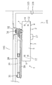
図1〜図3において、101は建物のドア開口部を示し、該ドア開口部101は、上枠102、左右の一対の竪枠103及び下枠(図示せず)で矩形に囲まれた空間で構成され、ドア104が上記ドア開口部101を開閉可能にヒンジ105を介して一方の竪枠103に取り付けられている。上記ドア104は、この発明の実施形態に係るドアクローザ1により開状態からゆっくりと自動的に閉じるようになっている。
1-3, 101 shows the door opening part of a building, and this
上記ドアクローザ1は、右開き(右勝手)のパラレル形タイプであり、ドアクローザ本体2を備えている。該ドアクローザ本体2は、作動油(図示せず)が充填された密閉空間3a(図4参照)を有するハウジング3を備え、該ハウジング3は取付金具4(図3参照)を介して上記ドア104上端に取り付けられている。この取付金具4は、一端(図3右端)にU字状引掛部4aが形成されているとともに、他端(図3左端)に斜めに起き上がった取付片部4bが形成されている。
The door closer 1 is a right-opening (right-handed) parallel type and includes a door
上記ハウジング3は、正面壁5、背面壁6、上面壁7、下面壁8及び左右一対の側面壁9の6面で直方体形状に形成され、上記背面壁6側には、上面壁7、下面壁8及び左右の側面壁9で囲まれた凹陥部10(図4参照)が形成されている。また、該凹陥部10の一端側(図4右端側)には、掛止ピン11が上面壁7と下面壁8とに上下に橋絡されて配設されている。さらに、上記一方(図4左側)の側面壁9には、ネジ挿通孔9aが上下に2個貫通形成されている(図6参照)。
The
そして、上記ドアクローザ本体2をドア104上端の内側に取り付けるには、まず、取付金具4をドア104上端に配置し、ネジ12(図1及び図2参照)を取付金具4の4個のネジ挿通孔(図示せず)に挿通してドア104にねじ込むことで、取付金具4をドア104上端の内側に取り付ける。
In order to attach the door
次いで、ドアクローザ本体2を上記取付金具4の正面に配置し、取付金具4の引掛部4aをハウジング3の掛止ピン11に引っ掛けて取付金具4をハウジング3の凹陥部10に配置する。この状態から、ネジ13(図3参照)をハウジング3(図3左側の側面壁9)の2個のネジ挿通孔9aと取付金具4の2個のネジ孔(図示せず)に螺合させることで、ドアクローザ本体2を取付金具4を介してドア104上端の内側に取り付ける。
Next, the door
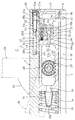
上記ハウジング3内部(密閉空間3a)には、図4に示すように、ピストン14がピストン付勢手段としての第1コイルスプリング15のバネ力により図4右方向に付勢された状態で往復移動可能に配置され、密閉空間3aがピストン14により高圧室A(図4右側の小領域)と低圧室B(図4左側の大領域)とに区画されている。図4中、16は、上記ピストン14の第1コイルスプリング15側の端面に取り付けられたスプリング座金具であり、該スプリング座金具16の中央には連通孔16aが形成されている。また、17は左右一対のエンドプラグであり、これらエンドプラグ17は、外周の雄ねじ部17aを上記両側面壁9の嵌合孔9b内周の雌ねじ部9cに螺合させることで嵌合孔9bに嵌着されている。
In the housing 3 (sealed
上記ピストン14の内部には空洞部14aが形成され、該空洞部14aは第1通路18を介して上記高圧室Aに連通しているとともに、第2通路19及び上記スプリング座金具16の連通孔16aを介して上記低圧室Bに連通している。上記第1通路18は、空洞部側通路18aと、該空洞部側通路18aよりも大きい高圧室側通路18bとからなり、この高圧室側通路18bにチェック弁20が介設され、該チェック弁20により上記高圧室Aと低圧室Bとを連通・遮断するようにしている。つまり、上記空洞部14aは低圧室Bの一部を構成している。このチェック弁20は、上記高圧室側通路18bに嵌着された弁本体21を備え、該弁本体21内には、ボール収容部21aが上記空洞部側通路18aと高圧室Aとに連通するように形成され、ボール22が上記ボール収容部21aに移動可能に収容されている。そして、上記チェック弁20は、ドア閉状態では高圧室Aの内圧で上記ボール22を空洞部側通路18aに通ずるボール収容部21a内壁に押し付けて空洞部側通路18aを閉じ、高圧室A側の作動油が低圧室B側に流出しないようにしている。
A
上記ピストン14の空洞部14aには、ラック・ピニオン機構23が組み込まれている。該ラック・ピニオン機構23は、空洞部14a内壁に形成されたラック24と、該ラック24に噛合するピニオン25とで構成され、該ピニオン25には、回転軸26が上記ハウジング3を上下に貫挿するように回転一体に連結されている。図1及び図2中、27は回転軸26の下端を覆い隠す円筒形のカップである。
A rack and
上記回転軸26の上端には、リンク機構28の一端が連結されるとともに、該リンク機構28の他端は建物のドア開口部101の上枠102側に連結されている。具体的には、上記リンク機構28は、メインアーム29と連結アーム30とからなり、上記メインアーム29の一端が上記回転軸26の上端に連結され、該メインアーム29の他端には、上記連結アーム30の一端が軸31回りに回転自在に連結されている。一方、上記ドア開口部101の上枠102には、ステー(三角板)32の基端が4個のネジ33(図3参照)を上枠102にねじ込むことで取り付けられており、該ステー32の先端には上記連結アーム30の他端が軸34回りに回転自在に連結されている。
One end of a
上記ハウジング3の他方(図3及び図4右側)の側面壁9には、3個の速度調整弁35がエンドプラグ17の外側で図5左上と右上に2個、左下に1個位置するように挿着されている。これら速度調整弁35は、図7に示すように、基端にドライバー等の操作工具を挿入係合するプラス型の係合溝35aが、中途部に雄ネジ部35bが、先端側に軸部35cが、該軸部35c先端に切欠部35dがそれぞれ形成された軸形状をしており、上記雄ネジ部35bの基端側にはシール用のOリング36が外嵌合されている。
On the
一方、上記図3及び図4右側の側面壁9の速度調整弁35対応箇所には、3個の第1挿着孔37(図7参照)が第1連通路38aを介して上記高圧室Aに連通するように、かつ第2連通路38b及び図示しない流路を介して上記低圧室Bに連通するように形成され、これら第1挿着孔37内壁には、上記速度調整弁35の雄ネジ部35bが螺合する雌ネジ部37aが形成されている。
On the other hand, three first insertion holes 37 (see FIG. 7) are provided in the high pressure chamber A via the
そして、上記速度調整弁35を上記第1挿着孔37に挿入して雄ネジ部35bを雌ネジ部37aに螺合させ、この状態で、軸部35c周りに形成された隙間及び上記切欠部35dを介して上記第1連通路38aと第2連通路38bとを連通させ、これにより、上記高圧室Aと低圧室Bとが連通し、速度調整弁35をドライバー等の操作工具で軸方向に螺進退させて切欠部35dの位置を変えることで該切欠部35dによる流路を広狭変化させ、上記ピストン14の移動に連動して上記高圧室Aから低圧室Bに流出する作動油の流量を制御することでドア104の閉速度を調整するようにしている。
Then, the
上記ハウジング3の図3及び図4右側の側面壁9には、リリーフ弁39がエンドプラグ17の外側で図5右下に位置するように開閉作動可能な状態と、開作動不能な状態とに切換え可能に挿着されている。図8〜図10はリリーフ弁39が開閉作動可能な状態に切り換えられた配置を示す。該リリーフ弁39は、図8に示すように、外部からの進退操作により位置調整可能な軸状の弁本体40、ボール41、軸部42aの一端に上記ボール41を支持する鍔状受座部42bが張り出し形成された軸状のボール受座42、及び開閉付勢手段としての第2コイルスプリング43を備え、上記ボール41とボール受座42とで開閉手段が構成されている。上記弁本体40は、基端にドライバー等の操作工具を挿入係合するプラス型の係合溝40aが、中途部に雄ネジ部40bがそれぞれ形成され、先端側及び上記雄ネジ部40bの基端側にはシール用のOリング44がそれぞれ外嵌合されている。また、上記弁本体40には、連絡路40cが先端に開口するように形成され、該連絡路40cは弁本体40中程で側方に開口している。
The
一方、上記図3及び図4右側の側面壁9のリリーフ弁39対応箇所には、第2挿着孔45(図8参照)が第3連通路46aを介して高圧室Aに連通するように、かつ第4連通路46b及び図示しない流路を介して上記低圧室Bに連通するように形成され、第2挿着孔45内壁には、上記弁本体40の雄ネジ部40bが螺合する雌ネジ部45aが形成されている。
On the other hand, the second insertion hole 45 (see FIG. 8) communicates with the high pressure chamber A via the
そして、上記第2コイルスプリング43を第2挿着孔45の底部45b側に挿入するとともに、上記ボール受座42の軸部42aを第2コイルスプリング43内に挿入して受座部42bを第2コイルスプリング43の端部に当接させ、さらに、上記ボール41を第2挿着孔45に挿入するとともに、上記弁本体40を第2挿着孔45に挿入して雄ネジ部40bを雌ネジ部45aに螺合させ、外部からのドライバー等の操作工具による進退操作によりその挿入位置を調整して上記ボール41を受座部42bと弁本体40先端との間に介在させる。この状態で、ボール41は第2コイルスプリング43のバネ力でボール受座42を介して付勢され、該ボール受座42と弁本体40とで挟持されて弁本体40の連絡路40cを閉塞し、第3連通路46a(高圧室A)と第4連通路46b(低圧室B)とを遮断している(図8及び図9参照)。
Then, the
一方、高圧室Aの内圧が上昇すると、ボール41が図8及び図9で左方向に押圧されて第2コイルスプリング43が圧縮され、ボール41を第2コイルスプリング43のバネ力に抗して弁本体40先端から離れさせて該弁本体40の連絡路40cを開放し、弁本体40の連絡路40c及び第2挿着孔45を介して第3連通路46aと第4連通路46bとを連通させ、これにより、上記高圧室Aと低圧室Bとが連通するようになっている(図10参照)。
On the other hand, when the internal pressure of the high-pressure chamber A rises, the
また、上記リリーフ弁39は、開作動不能な状態である図12に示すように、弁本体40を図中左方向に螺進させることにより、連絡路40cを第3連通路46aから切り離すとともに、ボール受座42を弁本体40により押圧して軸部42a先端を第2挿着孔45の底部45bに当接させ、この状態で、上記ボール41をボール受座42と弁本体40とで挟持して該弁本体40の連絡路40cをボール41で閉じ、高圧室Aの作動油が低圧室Bに排出しないようにすることもできる。これに限らず、弁本体40の位置を外部から調整することで第2コイルスプリング43のバネ力を可変とし、リリーフ弁39の開閉作動タイミング、つまり連絡路40cの開閉タイミングを高圧室Aの内圧に応じて自在に変更することも簡単に行うことができる。
Further, as shown in FIG. 12, which is in a state in which the
このように構成されたドアクローザ1では、ドア104を図3で矢印X1方向(時計回り)に開操作すると、その回転動作がリンク機構28を介して回転軸26に伝達されて該回転軸26が図3で矢印X2方向(反時計回り、図4で時計回り)に回転する。これにより、ピニオン25が図4で矢印X2方向(時計回り)に回転し、ピストン14がラック・ピニオン機構23を介して第1コイルスプリング15のバネ力に抗して該第1コイルスプリング15を圧縮しながらハウジング3の密閉空間3aで低圧室B縮小方向、つまり図4で矢印X3方向に(左方向)に直線移動する。これにより、低圧室Bの作動油がスプリング受座16の連通孔16a、第2通路19、空洞部14a及び第1通路18を経てボール22を高圧室A側に動かして第1通路18を開き、高圧室Aに流出する(図7参照)。そして、ドア104が閉方向に移動する力を蓄積しながら開かれる。
In the
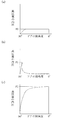
ドア104から手を離すと、平時は、上記圧縮された第1コイルスプリング15がその反発力により伸長し、該第1コイルスプリング15のバネ力によりピストン14がハウジング3の密閉空間3aで高圧室A縮小方向、つまり図4で矢印Y3方向(右方向)に直線移動する。この際、第1通路18は、チェック弁20のボール22が高圧室Aの内圧によりボール収容部21a内壁に押し付けられることで閉じられているので、高圧室Aの作動油は第1通路18を経て低圧室Bに流出せず、速度調整弁35及び図示しない流路を経て低圧室Bに流出する(図9参照)。これにより、ピニオン25が図4で矢印Y2方向(反時計回り)に回転し、回転軸26が図3で矢印Y2方向(時計回り)に回転し、この回転力がリンク機構28に伝達されてドア104が図3で矢印Y1方向(反時計回り)にゆっくりと自動的に閉じる。この際、リリーフ弁39は、開閉作動可能な状態では、図9に示すように、ボール41を第2コイルスプリング43のバネ力により弁本体40先端に押し付けて連絡路40cを閉じ、上記高圧室Aと低圧室Bとを遮断している。その時の高圧室Aから低圧室Bに速度調整弁35を経て流出する作動油の流量をfとし、高圧室Aの圧力をP0とする(図9参照)。その圧力変化を図11(a)に示す。
When the hand is released from the
一方、ドア104が閉じている途中で強制的に閉じる等して閉方向の外力がドア104に作用すると、高圧室Aの内圧が上昇し、上記リリーフ弁39は、開閉作動可能な状態では、図10に示すように、ボール41を上記高圧室Aの上昇した内圧で第2コイルスプリング43のバネ力に抗して弁本体40先端から離れさせて連絡路40cを開け、上記高圧室Aと低圧室Bとを連通して高圧室Aの作動油を上記リリーフ弁39を経て低圧室Bに排出する。この際、高圧室Aから低圧室Bには、速度調整弁35及びリリーフ弁39の両者から作動油が流出する。つまり、高圧室Aから低圧室Bに流出する作動油の流量は、速度調整弁35を経て流出する作動油の流量fに、リリーフ弁39を経て流出する作動油の流量Fが加算された量(f+F)となる(図10参照)。その時の高圧室Aの圧力をP1とすると、P1>P0となり、その圧力変化を図11(b)に示す。因みに、リリーフ弁39がない場合やリリーフ弁39が機能しない開作動不能な状態では、高圧室Aから低圧室Bに流出する作動油の流量は、速度調整弁35を経て流出する作動油の流量fのみで、高圧室Aの作動油の圧力がP1よりも高いP2にまで上昇する。その圧力変化を図11(c)に示す。
On the other hand, when an external force in the closing direction acts on the
このように、上記の実施形態では、ハウジング3に速度調整弁35以外にリリーフ弁39を設けて、ドア104を閉じている途中で強制的に閉じる等して閉方向の外力がドア104に作用した際に、上記リリーフ弁39が開閉作動可能な状態では、リリーフ弁39のボール41を第2コイルスプリング43のバネ力に抗して弁本体40の連絡路40c先端から離れさせて該連絡路40cを開き、高圧室Aの作動油を上記リリーフ弁39を経て低圧室Bに排出するようにしているので、高圧室Aの内圧が過度に高まる事態を回避してドアクローザ1の抵抗を増大しないようにすることができ、これにより、ドア104のヒンジ105やドア開口部101の上枠102に無理な力が掛からないようにしてこれらの破損を防止することができる。
As described above, in the above embodiment, the
また、上記の実施形態では、リリーフ弁39の弁本体40の位置を外部から進退操作により調整して第2コイルスプリング43のバネ力を変えることで、連絡路49の開閉タイミング、つまり高圧室Aから低圧室Bに排出される作動油の排出タイミングを高圧室Aの内圧に応じて自在に変更できるので、ドア104のサイズや閉方向に作用する外力の大きさが変わってもドアクローザ1の抵抗を適正に調整でき、ドア104のヒンジ105やドア開口部101の上枠102に無理な力が掛かる事態を確実に防止して、これらの破損防止を保証できて利便性を高めることができる。
Further, in the above embodiment, the position of the
さらに、上記の実施形態では、リリーフ弁39が開作動不能な状態では、リリーフ弁39のボール受座42の軸部42a先端を、図12に示すように、第2挿着孔45の底部45aに当接させて、ボール41を高圧室Aの内圧に関係なく動かないようにしてリリーフ弁39の機能を停止させることで、ドア104を閉じている途中で閉方向の外力がドアに作用しても、リリーフ弁39は働かず、なきに等しい状態となる。したがって、ドア104の種類や適用場所等使い勝手に応じてリリーフ弁39を機能させたり、機能させなくすることができ、2種類のドア104を用意せずに済むので非常に経済的である。
Furthermore, in the above-described embodiment, when the
(参考例1)
図13〜図15は参考例1に係るドアクローザ1を示す。この参考例1では、実施形態で採用したリリーフ弁39の機能をチェック弁20に持たせたものであり、そのほかは実施形態と同様であるので、同一の構成箇所には同一の符号を付してその詳細な説明を省略し、以下異なる点のみを説明する。
(Reference Example 1)
13 to 15 show the
すなわち、ピストン14の第1通路18を構成する高圧室側通路18bを実施形態よりも空洞部側通路18a側に広げ、かつチェック弁20を高圧室側通路18bに沿って移動可能に挿着するとともに、貫通孔47aが形成された脱落防止プレート47を上記高圧室側通路18bの高圧室A側の端面に取り付け、さらに、コイルスプリング48を高圧室側通路18b内に縮装してそのバネ力で上記チェック弁20を脱落防止プレート47に押し付けている。また、弁本体21の高圧室A側の端部外周に段下部21bを全周に亘って形成している。一方、上記ピストン14の高圧室A側に、バイパス通路49を高圧室側通路18bの高圧室A寄りと空洞部14aとを連通するように形成している。図中、50はチェック弁37の弁本体41に外嵌めされたシール用のOリングである。
That is, the high pressure
そして、上記チェック弁20は、平時は、ドア閉状態で高圧室Aの内圧で上記ボール22をコイルスプリング48のバネ力に抗して空洞部側通路18aに通ずるボール収容部21a内壁に押し付けて空洞部側通路18aを閉じ、高圧室A側の作動油が低圧室B側に流出しないようにしている。
In the normal state, the
図13はドア閉状態から開操作した際のボール22の位置を示し、該ボール22は高圧室A側に移動して高圧室Aと低圧室Bとを連通させて第1通路18を開き、低圧室Bの作動油が高圧室Aに流出している状態である。
FIG. 13 shows the position of the
図14は開状態のドア104から手を離した際の平時における作動油の流れを示す。つまり、平時は、ドア開状態で圧縮されている第1コイルスプリング15がその反発力により伸長し、該第1コイルスプリング15のバネ力によりピストン14がハウジング3の密閉空間3aで高圧室A縮小方向(図14で右方向)に直線移動する。この際、第1通路18は、チェック弁20のボール22が高圧室Aの内圧によりボール収容部21a内壁に押し付けられることで閉じられている。また、バイパス通路49の高圧室A側の端部は弁本体21で閉じられている。したがって、高圧室Aの作動油は第1通路18及びバイパス通路49を経て低圧室Bに流出せず、速度調整弁35及び図示しない流路を経て低圧室Bに流出する。
FIG. 14 shows the flow of hydraulic oil during normal times when the hand is released from the opened
一方、ドア104が閉じている途中で強制的に閉じる等して閉方向の外力がドア104に作用した際には、上記弁本体21を高圧室Aの上昇した内圧でコイルスプリング48のバネ力に抗して低圧室B側に移動させて上記バイパス通路49の高圧室A側の端部を開け、チェック弁20の段下部21bとバイパス通路49とを連通させて上記高圧室Aと低圧室Bとを連通し、高圧室Aの作動油をバイパス通路49を経て低圧室Bに排出するようになっている(図15参照)。
On the other hand, when an external force in the closing direction acts on the
この参考例1によると、特許文献1や実施形態に比べてリリーフ弁がいらない分だけ部品点数が少なくなり、ドアクローザ1のコストを低減できるメリットがある。また、この参考例1では、リリーフ弁39の機能をチェック弁20が果たすため、ドア104を閉じている途中で強制的に閉じる等して閉方向の外力がドア104に作用した際、高圧室Aの内圧上昇を効果的に抑制して、無理な力が掛かることによるドア104のヒンジ105やドア開口部101の上枠102の破損を防止することができることに関しては、実施形態と同様である。
According to the reference example 1, the number of parts is reduced by the amount that does not require a relief valve as compared with
(参考例2)
図16及び図17は、参考例2に係るドアクローザ1を示す。この参考例2では、実施形態のリリーフ弁39と基本構成が同様であるリリーフ弁51をピストン14に挿着している。そのほかは実施形態と同様であるので、同一の構成箇所には同一の符号を付してその詳細な説明を省略し、以下異なる点のみを説明する。
(Reference Example 2)
16 and 17 show the
すなわち、この参考例2では、リリーフ弁51は、軸状の弁本体52、ボール53、実施形態のボール受座42と同様に軸部の一端に鍔状受座部が張り出し形成された軸状のボール受座54、及びコイルスプリング55を備え、上記弁本体52には連絡路56が軸方向に貫通形成されている。
That is, in this reference example 2, the
一方、ピストン14には、挿着孔57が形成されているとともに、通油路58が上記挿着孔57と直交する方向に連続して延びて第1通路18の空洞部側通路18aに接続され、上記リリーフ弁51が上記挿着孔57に挿着されている。
On the other hand, an
そして、上記リリーフ弁51は、平時は、ドア閉状態で高圧室Aの内圧で上記ボール53をコイルスプリング55のバネ力に抗して弁本体52に押し付けて連絡路56を閉じ、高圧室A側の作動油が低圧室B側に流出しないようにしている。また、第1通路18は、チェック弁20のボール22が高圧室Aの内圧によりボール収容部21a内壁に押し付けられることで閉じられている。
When the door is closed, the
この状態からドア104を開操作すると、チェック弁20のボール22は高圧室A側に移動して第1通路18を開き、高圧室Aと低圧室Bとを連通させて低圧室Bの作動油が高圧室Aに流出する。リリーフ弁51の連絡路56は閉じたままである。
When the
図16は開状態のドア104から手を離した際の平時における作動油の流れを示す。つまり、平時は、ドア開状態で圧縮されている第1コイルスプリング15がその反発力により伸長し、該第1コイルスプリング15のバネ力によりピストン14がハウジング3の密閉空間3aで高圧室A縮小方向(図16で右方向)に直線移動する。この際、第1通路18は、チェック弁20のボール22が高圧室Aの内圧によりボール収容部21a内壁に押し付けられることで閉じられている。リリーフ弁51の連絡路56は依然として閉じたままである。したがって、高圧室Aの作動油は第1通路18及び連絡路56を経て低圧室Bに流出せず、速度調整弁35及び図示しない流路を経て低圧室Bに流出する(図16参照)。
FIG. 16 shows the flow of hydraulic oil during normal times when the hand is released from the opened
一方、ドア104が閉じている途中で強制的に閉じる等して閉方向の外力がドア104に作用した際には、上記弁本体21を高圧室Aの上昇した内圧でコイルスプリング55のバネ力に抗して低圧室B側に移動させて連絡路56を開け、上記高圧室Aと低圧室Bとを通油路58を介して連通して高圧室Aの作動油を低圧室Bに排出するようになっている(図17参照)。
On the other hand, when an external force in the closing direction is applied to the
この参考例2によると、特許文献1の如きリリーフ弁39の位置調整はできないものの、リリーフ弁51があることで、ドア104を閉じている途中で強制的に閉じる等して閉方向の外力がドア104に作用した際、高圧室Aの作動油の圧力上昇を効果的に抑制して、無理な力が掛かることによるドア104のヒンジ105やドア開口部101の上枠102の破損を防止することができることに関しては、実施形態と同様である。
According to this reference example 2, although the position of the
なお、上記の実施形態では、リリーフ弁39の開閉手段をボール41とボール受座42とで構成したが、ボール41をなくしてボール受座42に相当する軸部材のみで開閉手段を構成し、該軸部材で弁本体40の連絡路40cを開閉するようにしてもよい。
In the above embodiment, the opening / closing means of the
また、上記の実施形態では、リリーフ弁39をハウジング3の側面壁9の第2挿着孔45に挿着したが、高圧室Aの作動油を低圧室Bに排出でき、かつその内圧に応じて位置調整できる場所であればリリーフ弁39の挿着場所は問わない。
In the above embodiment, the
この発明は、開いたドアをゆっくりと自動的に閉めるドアクローザ(ドア自閉装置)について有用である。 The present invention is useful for a door closer (door self-closing device) that slowly and automatically closes an open door.
A 高圧室
B 低圧室
1 ドアクローザ
3 ハウジング
3a 密閉空間
14 ピストン
15 第1コイルスプリング(ピストン付勢手段)
20 チェック弁
23 ラック・ピニオン機構
26 回転軸
28 リンク機構
35 速度調整弁
39 リリーフ弁
40 弁本体
41 ボール(開閉手段)
42 ボール受座(開閉手段)
43 第2コイルスプリング(開閉付勢手段)
45 第2挿着孔
45b 第2挿着孔の底部
40c 連絡路
101 ドア開口部
102 上枠
104 ドア
A High pressure chamber B
20
42 Ball seat (opening / closing means)
43 Second coil spring (open / close biasing means)
45
Claims (4)
上記密閉空間にピストン付勢手段により付勢された状態で往復移動可能に配置され、密閉空間を高圧室と低圧室とに区画するピストンと、
該ピストンに設けられ、上記高圧室と低圧室とを連通・遮断するチェック弁と、
上記ピストンに組み込まれたラック・ピニオン機構と、
該ラック・ピニオン機構のピニオンに上記ハウジングを上下に貫挿するように回転一体に連結された回転軸と、
一端が上記回転軸の上端に連結されるとともに、他端が建物のドア開口部の上枠側に連結されたリンク機構と、
上記ハウジングに挿着され、上記ピストンの移動に連動して上記高圧室から低圧室に流出する作動油の流量を制御することでドアの閉速度を調整する速度調整弁とを備え、
ドアの開操作によりその回転動作を上記リンク機構、回転軸及びラック・ピニオン機構を介してピストンの直線動作に変換して該ピストンを上記ピストン付勢手段の付勢力に抗してハウジングの密閉空間で低圧室縮小方向に移動させ、作動油を低圧室から上記チェック弁を経て高圧室に流出させてドアの閉方向に移動する力を蓄積し、ドアから手を離すことにより上記ピストンを上記ピストン付勢手段の付勢力によりハウジングの密閉空間で高圧室縮小方向に移動させ、高圧室の作動油を上記速度調整弁を経て低圧室に流出させてドアをゆっくりと自動的に閉めるように構成されているドアクローザであって、
上記ハウジングには、平時は、上記高圧室と低圧室とを遮断する一方、ドアが閉じている途中で閉方向の外力がドアに作用した際には、上記高圧室と低圧室とを連通して高圧室の作動油を低圧室に排出するリリーフ弁が、開閉作動可能な状態と、開作動不能な状態とに切換え可能に設けられていることを特徴とするドアクローザ。 A housing having a sealed space filled with hydraulic oil;
A piston that is reciprocally moved in a state of being biased by the piston biasing means in the sealed space, and that divides the sealed space into a high-pressure chamber and a low-pressure chamber;
A check valve provided in the piston for communicating / blocking the high pressure chamber and the low pressure chamber;
A rack and pinion mechanism incorporated in the piston;
A rotating shaft connected integrally to the pinion of the rack and pinion mechanism so as to penetrate the housing up and down;
A link mechanism having one end connected to the upper end of the rotating shaft and the other end connected to the upper frame side of the door opening of the building;
A speed adjustment valve that is inserted into the housing and adjusts the closing speed of the door by controlling the flow rate of hydraulic oil flowing out from the high pressure chamber to the low pressure chamber in conjunction with the movement of the piston;
When the door is opened, the rotational movement is converted into a linear movement of the piston via the link mechanism, the rotary shaft and the rack and pinion mechanism, and the piston is resisted against the biasing force of the piston biasing means. To move the hydraulic oil from the low-pressure chamber to the high-pressure chamber through the check valve, accumulate the force to move in the door closing direction, and release the hand from the door to move the piston to the piston. The urging force of the urging means moves in the high pressure chamber shrinking direction in the sealed space of the housing, and the hydraulic oil in the high pressure chamber flows out to the low pressure chamber via the speed adjustment valve, so that the door is slowly and automatically closed. A door closer,
During normal times, the housing shuts off the high pressure chamber and the low pressure chamber, and when an external force in the closing direction acts on the door while the door is closed, the high pressure chamber and the low pressure chamber communicate with each other. A door closer characterized in that a relief valve that discharges hydraulic oil from the high-pressure chamber to the low-pressure chamber is provided so as to be switchable between a state where it can be opened and closed and a state where it cannot be opened.
上記ハウジングには、挿着孔が上記高圧室と低圧室とを連絡するように形成され、
該挿着孔には、上記リリーフ弁が外部からの進退操作により位置調整可能に挿着され、
該リリーフ弁は、開閉作動可能な状態で、位置を調整することで開閉作動タイミングを高圧室の内圧に応じて自在に変更できるように構成されていることを特徴とするドアクローザ。 The door closer according to claim 1,
An insertion hole is formed in the housing so as to connect the high pressure chamber and the low pressure chamber,
The relief valve is inserted into the insertion hole so that the position thereof can be adjusted by a forward / backward operation from the outside,
The door closer is configured so that the opening and closing operation timing can be freely changed according to the internal pressure of the high pressure chamber by adjusting the position in a state where the relief valve can be opened and closed.
上記リリーフ弁は、連絡路が先端に開口するように形成されかつ進退操作により位置調整可能な軸状の弁本体と、上記連絡路を開閉する開閉手段と、該開閉手段を付勢する開閉付勢手段とを備え、
開閉作動可能な状態では、平時は、上記開閉手段を開閉付勢手段の付勢力により弁本体先端に押し付けて連絡路を閉じ、上記高圧室と低圧室とを遮断する一方、ドアが閉じている途中で閉方向の外力がドアに作用した際には、上記開閉手段を高圧室の内圧で開閉付勢手段の付勢力に抗して弁本体先端から離れさせて連絡路を開け、上記高圧室と低圧室とを連通して高圧室の作動油を低圧室に排出するように構成されていることを特徴とするドアクローザ。 The door closer according to claim 2,
The relief valve includes a shaft-shaped valve body that is formed so that a communication path is opened at a tip and can be adjusted by advancing and retreating operation, an opening / closing means that opens and closes the communication path, and an opening / closing mechanism that biases the opening / closing means. Power means,
In a state where the opening / closing operation is possible, during normal times, the opening / closing means is pressed against the tip of the valve body by the urging force of the opening / closing urging means to close the communication path and shut off the high pressure chamber and the low pressure chamber, while the door is closed. When an external force in the closing direction acts on the door halfway, the opening / closing means is moved away from the valve body tip against the urging force of the opening / closing urging means by the internal pressure of the high pressure chamber, and the communication path is opened. The door closer is configured to communicate with the low pressure chamber and to discharge the hydraulic oil in the high pressure chamber to the low pressure chamber.
上記リリーフ弁は、開作動不能な状態では、上記弁本体を進出させて上記開閉手段を挿着孔の底部に当接するように押圧し、弁本体の連絡路を開閉手段で閉じるように構成されていることを特徴とするドアクローザ。 The door closer according to claim 3,
In a state in which the relief valve cannot be opened, the relief valve is configured to advance the valve body, press the opening / closing means so as to contact the bottom of the insertion hole, and close the communication path of the valve body by the opening / closing means. A door closer.
Priority Applications (1)
| Application Number | Priority Date | Filing Date | Title |
|---|---|---|---|
| JP2008183083A JP4864944B2 (en) | 2008-07-14 | 2008-07-14 | Door closer |
Applications Claiming Priority (1)
| Application Number | Priority Date | Filing Date | Title |
|---|---|---|---|
| JP2008183083A JP4864944B2 (en) | 2008-07-14 | 2008-07-14 | Door closer |
Publications (2)
| Publication Number | Publication Date |
|---|---|
| JP2010019053A true JP2010019053A (en) | 2010-01-28 |
| JP4864944B2 JP4864944B2 (en) | 2012-02-01 |
Family
ID=41704219
Family Applications (1)
| Application Number | Title | Priority Date | Filing Date |
|---|---|---|---|
| JP2008183083A Active JP4864944B2 (en) | 2008-07-14 | 2008-07-14 | Door closer |
Country Status (1)
| Country | Link |
|---|---|
| JP (1) | JP4864944B2 (en) |
Cited By (5)
| Publication number | Priority date | Publication date | Assignee | Title |
|---|---|---|---|---|
| JP2017534780A (en) * | 2014-10-06 | 2017-11-24 | イン&テック エス.アール.エル. | Hinge device for doors, shutters, etc. |
| JP2019085729A (en) * | 2017-11-02 | 2019-06-06 | リョービ株式会社 | Floor hinge |
| KR20190089359A (en) * | 2018-01-22 | 2019-07-31 | 김경태 | Door closer |
| JP2019127699A (en) * | 2018-01-22 | 2019-08-01 | 株式会社ムラコシ精工 | Cover member and door hinge |
| JP2020007893A (en) * | 2018-07-10 | 2020-01-16 | 松之門控設備股▲分▼有限公司 | Glass door automatic return device |
Citations (2)
| Publication number | Priority date | Publication date | Assignee | Title |
|---|---|---|---|---|
| JPS58100974A (en) * | 1981-12-09 | 1983-06-15 | Kobe Steel Ltd | Controlling method for amount of feeding of flux for submerged arc welding |
| JPH10196213A (en) * | 1997-01-14 | 1998-07-28 | Nippon Door Check Mfg Corp | Automatic door closing device |
-
2008
- 2008-07-14 JP JP2008183083A patent/JP4864944B2/en active Active
Patent Citations (2)
| Publication number | Priority date | Publication date | Assignee | Title |
|---|---|---|---|---|
| JPS58100974A (en) * | 1981-12-09 | 1983-06-15 | Kobe Steel Ltd | Controlling method for amount of feeding of flux for submerged arc welding |
| JPH10196213A (en) * | 1997-01-14 | 1998-07-28 | Nippon Door Check Mfg Corp | Automatic door closing device |
Cited By (7)
| Publication number | Priority date | Publication date | Assignee | Title |
|---|---|---|---|---|
| JP2017534780A (en) * | 2014-10-06 | 2017-11-24 | イン&テック エス.アール.エル. | Hinge device for doors, shutters, etc. |
| JP2019085729A (en) * | 2017-11-02 | 2019-06-06 | リョービ株式会社 | Floor hinge |
| KR20190089359A (en) * | 2018-01-22 | 2019-07-31 | 김경태 | Door closer |
| JP2019127699A (en) * | 2018-01-22 | 2019-08-01 | 株式会社ムラコシ精工 | Cover member and door hinge |
| KR102019588B1 (en) | 2018-01-22 | 2019-09-09 | 김경태 | Door closer |
| JP7029747B2 (en) | 2018-01-22 | 2022-03-04 | 株式会社ムラコシ精工 | Cover members and hinges for doors |
| JP2020007893A (en) * | 2018-07-10 | 2020-01-16 | 松之門控設備股▲分▼有限公司 | Glass door automatic return device |
Also Published As
| Publication number | Publication date |
|---|---|
| JP4864944B2 (en) | 2012-02-01 |
Similar Documents
| Publication | Publication Date | Title |
|---|---|---|
| JP4864944B2 (en) | Door closer | |
| JP6327421B2 (en) | Fluid control valve | |
| JP5555198B2 (en) | Door closer | |
| EP1403549A3 (en) | Length-adjustable compression spring | |
| JP4864943B2 (en) | Door closer | |
| US20150300379A1 (en) | Cylinder control device | |
| JP6006150B2 (en) | Door closer | |
| JP6711712B2 (en) | Speed control valve for door closer | |
| JP2012201139A (en) | Integral power steering device | |
| JP3136304B2 (en) | Door closer | |
| KR102094187B1 (en) | Door closer | |
| KR200381570Y1 (en) | A door closer comprising a suspending device | |
| CN109267865B (en) | Door closer | |
| JP6228076B2 (en) | Door closer | |
| CN213381373U (en) | Electric hydraulic tool | |
| JP7122933B2 (en) | door closer | |
| RU2211964C2 (en) | Hydraulic drive | |
| JP7041419B2 (en) | Time delay valve and flow controller | |
| JP7182337B2 (en) | door closer | |
| KR101047611B1 (en) | Stationary door closers | |
| JP2013185407A (en) | Door closer | |
| JP7185816B2 (en) | closer device | |
| JP5939854B2 (en) | Door closer | |
| JP2557382Y2 (en) | Floor hinge | |
| KR200385701Y1 (en) | Bidirectional Operable Door Closer |
Legal Events
| Date | Code | Title | Description |
|---|---|---|---|
| A977 | Report on retrieval |
Free format text: JAPANESE INTERMEDIATE CODE: A971007 Effective date: 20111003 |
|
| TRDD | Decision of grant or rejection written | ||
| A01 | Written decision to grant a patent or to grant a registration (utility model) |
Free format text: JAPANESE INTERMEDIATE CODE: A01 Effective date: 20111011 |
|
| A01 | Written decision to grant a patent or to grant a registration (utility model) |
Free format text: JAPANESE INTERMEDIATE CODE: A01 |
|
| A61 | First payment of annual fees (during grant procedure) |
Free format text: JAPANESE INTERMEDIATE CODE: A61 Effective date: 20111109 |
|
| FPAY | Renewal fee payment (event date is renewal date of database) |
Free format text: PAYMENT UNTIL: 20141118 Year of fee payment: 3 |
|
| R150 | Certificate of patent or registration of utility model |
Ref document number: 4864944 Country of ref document: JP Free format text: JAPANESE INTERMEDIATE CODE: R150 Free format text: JAPANESE INTERMEDIATE CODE: R150 |
|
| R250 | Receipt of annual fees |
Free format text: JAPANESE INTERMEDIATE CODE: R250 |
|
| R250 | Receipt of annual fees |
Free format text: JAPANESE INTERMEDIATE CODE: R250 |
|
| R250 | Receipt of annual fees |
Free format text: JAPANESE INTERMEDIATE CODE: R250 |
|
| R250 | Receipt of annual fees |
Free format text: JAPANESE INTERMEDIATE CODE: R250 |
|
| R250 | Receipt of annual fees |
Free format text: JAPANESE INTERMEDIATE CODE: R250 |
|
| R250 | Receipt of annual fees |
Free format text: JAPANESE INTERMEDIATE CODE: R250 |
|
| R250 | Receipt of annual fees |
Free format text: JAPANESE INTERMEDIATE CODE: R250 |
|
| S111 | Request for change of ownership or part of ownership |
Free format text: JAPANESE INTERMEDIATE CODE: R313115 |
|
| R350 | Written notification of registration of transfer |
Free format text: JAPANESE INTERMEDIATE CODE: R350 |
|
| R250 | Receipt of annual fees |
Free format text: JAPANESE INTERMEDIATE CODE: R250 |
|
| R250 | Receipt of annual fees |
Free format text: JAPANESE INTERMEDIATE CODE: R250 |
|
| S531 | Written request for registration of change of domicile |
Free format text: JAPANESE INTERMEDIATE CODE: R313531 |
|
| R350 | Written notification of registration of transfer |
Free format text: JAPANESE INTERMEDIATE CODE: R350 |
|
| R250 | Receipt of annual fees |
Free format text: JAPANESE INTERMEDIATE CODE: R250 |