JP2010017713A - Fluid cleaning apparatus - Google Patents
Fluid cleaning apparatus Download PDFInfo
- Publication number
- JP2010017713A JP2010017713A JP2009237412A JP2009237412A JP2010017713A JP 2010017713 A JP2010017713 A JP 2010017713A JP 2009237412 A JP2009237412 A JP 2009237412A JP 2009237412 A JP2009237412 A JP 2009237412A JP 2010017713 A JP2010017713 A JP 2010017713A
- Authority
- JP
- Japan
- Prior art keywords
- fluid
- unit
- treated
- photocatalyst
- adsorbent
- Prior art date
- Legal status (The legal status is an assumption and is not a legal conclusion. Google has not performed a legal analysis and makes no representation as to the accuracy of the status listed.)
- Granted
Links
- 239000012530 fluid Substances 0.000 title claims abstract description 249
- 238000004140 cleaning Methods 0.000 title abstract description 8
- 239000003463 adsorbent Substances 0.000 claims abstract description 175
- 239000011941 photocatalyst Substances 0.000 claims abstract description 133
- 239000000356 contaminant Substances 0.000 claims abstract description 105
- 238000001179 sorption measurement Methods 0.000 claims abstract description 33
- 239000000428 dust Substances 0.000 claims abstract description 31
- 238000011144 upstream manufacturing Methods 0.000 claims abstract description 18
- 238000000746 purification Methods 0.000 claims description 143
- 230000001699 photocatalysis Effects 0.000 claims description 44
- 239000003344 environmental pollutant Substances 0.000 claims description 27
- 231100000719 pollutant Toxicity 0.000 claims description 27
- 230000005284 excitation Effects 0.000 claims description 15
- 230000000694 effects Effects 0.000 abstract description 2
- 239000007789 gas Substances 0.000 description 116
- 239000000126 substance Substances 0.000 description 40
- KFZMGEQAYNKOFK-UHFFFAOYSA-N Isopropanol Chemical compound CC(C)O KFZMGEQAYNKOFK-UHFFFAOYSA-N 0.000 description 39
- 238000005259 measurement Methods 0.000 description 35
- OKTJSMMVPCPJKN-UHFFFAOYSA-N Carbon Chemical class [C] OKTJSMMVPCPJKN-UHFFFAOYSA-N 0.000 description 34
- 238000005342 ion exchange Methods 0.000 description 23
- 238000012546 transfer Methods 0.000 description 21
- 238000009835 boiling Methods 0.000 description 19
- 238000004519 manufacturing process Methods 0.000 description 18
- OKKJLVBELUTLKV-UHFFFAOYSA-N Methanol Chemical compound OC OKKJLVBELUTLKV-UHFFFAOYSA-N 0.000 description 15
- CBENFWSGALASAD-UHFFFAOYSA-N Ozone Chemical compound [O-][O+]=O CBENFWSGALASAD-UHFFFAOYSA-N 0.000 description 15
- QGZKDVFQNNGYKY-UHFFFAOYSA-N Ammonia Chemical compound N QGZKDVFQNNGYKY-UHFFFAOYSA-N 0.000 description 14
- CSCPPACGZOOCGX-UHFFFAOYSA-N Acetone Chemical compound CC(C)=O CSCPPACGZOOCGX-UHFFFAOYSA-N 0.000 description 13
- JHIVVAPYMSGYDF-UHFFFAOYSA-N cyclohexanone Chemical compound O=C1CCCCC1 JHIVVAPYMSGYDF-UHFFFAOYSA-N 0.000 description 12
- 239000000835 fiber Substances 0.000 description 12
- LFQSCWFLJHTTHZ-UHFFFAOYSA-N Ethanol Chemical compound CCO LFQSCWFLJHTTHZ-UHFFFAOYSA-N 0.000 description 11
- 230000007613 environmental effect Effects 0.000 description 10
- QTBSBXVTEAMEQO-UHFFFAOYSA-N Acetic acid Chemical compound CC(O)=O QTBSBXVTEAMEQO-UHFFFAOYSA-N 0.000 description 9
- ZWEHNKRNPOVVGH-UHFFFAOYSA-N 2-Butanone Chemical compound CCC(C)=O ZWEHNKRNPOVVGH-UHFFFAOYSA-N 0.000 description 8
- 229910021529 ammonia Inorganic materials 0.000 description 7
- 235000012431 wafers Nutrition 0.000 description 7
- 238000013459 approach Methods 0.000 description 6
- 150000001875 compounds Chemical class 0.000 description 6
- BDAGIHXWWSANSR-UHFFFAOYSA-N methanoic acid Natural products OC=O BDAGIHXWWSANSR-UHFFFAOYSA-N 0.000 description 6
- 239000005416 organic matter Substances 0.000 description 6
- 239000004065 semiconductor Substances 0.000 description 6
- 238000000354 decomposition reaction Methods 0.000 description 5
- 239000013541 low molecular weight contaminant Substances 0.000 description 5
- 239000000376 reactant Substances 0.000 description 5
- NBIIXXVUZAFLBC-UHFFFAOYSA-N Phosphoric acid Chemical group OP(O)(O)=O NBIIXXVUZAFLBC-UHFFFAOYSA-N 0.000 description 4
- GWEVSGVZZGPLCZ-UHFFFAOYSA-N Titan oxide Chemical compound O=[Ti]=O GWEVSGVZZGPLCZ-UHFFFAOYSA-N 0.000 description 4
- DOIRQSBPFJWKBE-UHFFFAOYSA-N dibutyl phthalate Chemical compound CCCCOC(=O)C1=CC=CC=C1C(=O)OCCCC DOIRQSBPFJWKBE-UHFFFAOYSA-N 0.000 description 4
- 239000011521 glass Substances 0.000 description 4
- 239000013542 high molecular weight contaminant Substances 0.000 description 4
- 239000007788 liquid Substances 0.000 description 4
- 238000000034 method Methods 0.000 description 4
- BWHMMNNQKKPAPP-UHFFFAOYSA-L potassium carbonate Chemical compound [K+].[K+].[O-]C([O-])=O BWHMMNNQKKPAPP-UHFFFAOYSA-L 0.000 description 4
- 229920006395 saturated elastomer Polymers 0.000 description 4
- ARXJGSRGQADJSQ-UHFFFAOYSA-N 1-methoxypropan-2-ol Chemical compound COCC(C)O ARXJGSRGQADJSQ-UHFFFAOYSA-N 0.000 description 3
- OSWFIVFLDKOXQC-UHFFFAOYSA-N 4-(3-methoxyphenyl)aniline Chemical compound COC1=CC=CC(C=2C=CC(N)=CC=2)=C1 OSWFIVFLDKOXQC-UHFFFAOYSA-N 0.000 description 3
- SECXISVLQFMRJM-UHFFFAOYSA-N N-Methylpyrrolidone Chemical compound CN1CCCC1=O SECXISVLQFMRJM-UHFFFAOYSA-N 0.000 description 3
- 238000004458 analytical method Methods 0.000 description 3
- BJQHLKABXJIVAM-UHFFFAOYSA-N bis(2-ethylhexyl) phthalate Chemical compound CCCCC(CC)COC(=O)C1=CC=CC=C1C(=O)OCC(CC)CCCC BJQHLKABXJIVAM-UHFFFAOYSA-N 0.000 description 3
- 238000011109 contamination Methods 0.000 description 3
- 239000013078 crystal Substances 0.000 description 3
- 230000001877 deodorizing effect Effects 0.000 description 3
- 238000003795 desorption Methods 0.000 description 3
- 239000010408 film Substances 0.000 description 3
- 235000019253 formic acid Nutrition 0.000 description 3
- 239000000463 material Substances 0.000 description 3
- 238000007146 photocatalysis Methods 0.000 description 3
- 230000008569 process Effects 0.000 description 3
- 238000012545 processing Methods 0.000 description 3
- OGIDPMRJRNCKJF-UHFFFAOYSA-N titanium oxide Inorganic materials [Ti]=O OGIDPMRJRNCKJF-UHFFFAOYSA-N 0.000 description 3
- YNQLUTRBYVCPMQ-UHFFFAOYSA-N Ethylbenzene Chemical compound CCC1=CC=CC=C1 YNQLUTRBYVCPMQ-UHFFFAOYSA-N 0.000 description 2
- 230000002378 acidificating effect Effects 0.000 description 2
- 229910000147 aluminium phosphate Inorganic materials 0.000 description 2
- 230000008859 change Effects 0.000 description 2
- 238000001914 filtration Methods 0.000 description 2
- 229910001872 inorganic gas Inorganic materials 0.000 description 2
- 238000009434 installation Methods 0.000 description 2
- 239000002245 particle Substances 0.000 description 2
- 230000000737 periodic effect Effects 0.000 description 2
- 229910000027 potassium carbonate Inorganic materials 0.000 description 2
- LLHKCFNBLRBOGN-UHFFFAOYSA-N propylene glycol methyl ether acetate Chemical compound COCC(C)OC(C)=O LLHKCFNBLRBOGN-UHFFFAOYSA-N 0.000 description 2
- 238000003860 storage Methods 0.000 description 2
- STCOOQWBFONSKY-UHFFFAOYSA-N tributyl phosphate Chemical compound CCCCOP(=O)(OCCCC)OCCCC STCOOQWBFONSKY-UHFFFAOYSA-N 0.000 description 2
- 229920000049 Carbon (fiber) Polymers 0.000 description 1
- MQIUGAXCHLFZKX-UHFFFAOYSA-N Di-n-octyl phthalate Natural products CCCCCCCCOC(=O)C1=CC=CC=C1C(=O)OCCCCCCCC MQIUGAXCHLFZKX-UHFFFAOYSA-N 0.000 description 1
- CTQNGGLPUBDAKN-UHFFFAOYSA-N O-Xylene Chemical compound CC1=CC=CC=C1C CTQNGGLPUBDAKN-UHFFFAOYSA-N 0.000 description 1
- VYPSYNLAJGMNEJ-UHFFFAOYSA-N Silicium dioxide Chemical compound O=[Si]=O VYPSYNLAJGMNEJ-UHFFFAOYSA-N 0.000 description 1
- XUIMIQQOPSSXEZ-UHFFFAOYSA-N Silicon Chemical compound [Si] XUIMIQQOPSSXEZ-UHFFFAOYSA-N 0.000 description 1
- 229910010413 TiO 2 Inorganic materials 0.000 description 1
- 239000002253 acid Substances 0.000 description 1
- 238000004887 air purification Methods 0.000 description 1
- QVGXLLKOCUKJST-UHFFFAOYSA-N atomic oxygen Chemical compound [O] QVGXLLKOCUKJST-UHFFFAOYSA-N 0.000 description 1
- 230000008901 benefit Effects 0.000 description 1
- 230000003749 cleanliness Effects 0.000 description 1
- 230000007423 decrease Effects 0.000 description 1
- 230000007547 defect Effects 0.000 description 1
- 238000004817 gas chromatography Methods 0.000 description 1
- 230000006872 improvement Effects 0.000 description 1
- 150000002500 ions Chemical group 0.000 description 1
- VNWKTOKETHGBQD-UHFFFAOYSA-N methane Chemical class C VNWKTOKETHGBQD-UHFFFAOYSA-N 0.000 description 1
- 238000006386 neutralization reaction Methods 0.000 description 1
- 230000003472 neutralizing effect Effects 0.000 description 1
- 239000007800 oxidant agent Substances 0.000 description 1
- 230000003647 oxidation Effects 0.000 description 1
- 238000007254 oxidation reaction Methods 0.000 description 1
- 238000006864 oxidative decomposition reaction Methods 0.000 description 1
- 230000001590 oxidative effect Effects 0.000 description 1
- 229910052760 oxygen Inorganic materials 0.000 description 1
- 239000001301 oxygen Substances 0.000 description 1
- 238000005192 partition Methods 0.000 description 1
- 229920001296 polysiloxane Polymers 0.000 description 1
- 230000009467 reduction Effects 0.000 description 1
- 238000012958 reprocessing Methods 0.000 description 1
- 230000004044 response Effects 0.000 description 1
- 230000000717 retained effect Effects 0.000 description 1
- 229910052710 silicon Inorganic materials 0.000 description 1
- 239000010703 silicon Substances 0.000 description 1
- 229910001220 stainless steel Inorganic materials 0.000 description 1
- 239000010935 stainless steel Substances 0.000 description 1
- 239000010409 thin film Substances 0.000 description 1
- XLYOFNOQVPJJNP-UHFFFAOYSA-N water Substances O XLYOFNOQVPJJNP-UHFFFAOYSA-N 0.000 description 1
- 239000008096 xylene Substances 0.000 description 1
Images


Abstract
Description
本発明は、光触媒と吸着剤フィルタを利用して気体又は液体中の汚染物質を高効率に分解、吸着することにより除去し、また長期にわたり清浄な流体を供給するのを可能にする、環境制御装置として好適に使用することができる、流体浄化装置に関する。 The present invention uses a photocatalyst and an adsorbent filter to remove pollutants in a gas or liquid by efficiently decomposing and adsorbing them, and to supply a clean fluid over a long period of time. The present invention relates to a fluid purification device that can be suitably used as a device.
近年、半導体デバイスの高集積化、高品質化が進み、高性能除塵フィルタ(一般にHEPAフィルタあるいはULPAフィルタという名称で知られる)で除去できないような微細な汚染物質、例えば気体の場合は、有機性ガス、無機性ガス、オゾンガス等の分子レベルの汚染物質が、デバイス製造上の不良原因として問題になっている。 In recent years, semiconductor devices have become highly integrated and high quality, and in the case of fine pollutants that cannot be removed by high performance dust filters (generally known as HEPA filters or ULPA filters), such as gases, organic Contaminants at the molecular level such as gas, inorganic gas, and ozone gas have become a problem as a cause of device manufacturing defects.
これらの有機性ガス、無機性ガス、オゾンガス等の汚染物質を吸着剤で除去することが知られている。吸着剤としては、活性炭、中和反応体を添着した活性炭、あるいはイオン交換繊維等のイオン交換基などから構成される吸着剤フィルタ(通称、ケミカルフィルタ)が提供されている。 It is known to remove contaminants such as organic gas, inorganic gas, ozone gas and the like with an adsorbent. As an adsorbent, an adsorbent filter (commonly known as a chemical filter) composed of activated carbon, activated carbon impregnated with a neutralizing reactant, or an ion exchange group such as an ion exchange fiber is provided.
吸着剤フィルタによる汚染物質の除去では、例えば、有機性ガス又はオゾンガスは、粒状又は繊維状の活性炭等によって物理的吸着もしくは分解して除去される。酸性ガスは、炭酸カリウムを添着させた粒状又は繊維状活性炭等によって化学的吸着するか、又はイオン交換繊維等のイオン交換基によってイオン交換することで除去される。アルカリ性ガスは、燐酸を添着させた粒状又は繊維状活性炭等によって化学的吸着するか、又はイオン交換繊維等のイオン交換基によってイオン交換して除去される。これらの吸着剤フィルタは層状のエレメントから構成され、一層又は二層以上の組み合わせを含むユニットとして使用されるのが一般的である。 In the removal of contaminants by the adsorbent filter, for example, organic gas or ozone gas is removed by physical adsorption or decomposition with granular or fibrous activated carbon or the like. The acidic gas is removed by chemical adsorption with granular or fibrous activated carbon impregnated with potassium carbonate, or ion exchange with ion exchange groups such as ion exchange fibers. Alkaline gas is chemically adsorbed by granular or fibrous activated carbon impregnated with phosphoric acid, or ion exchanged by ion exchange groups such as ion exchange fibers and removed. These adsorbent filters are generally composed of layered elements and are used as a unit including one layer or a combination of two or more layers.
吸着剤フィルタの吸着効率は、汚染物質の吸着量が飽和に近づくにつれて低下していき、吸着剤フィルタが完全に飽和した場合は、吸着剤フィルタを交換する必要がある。活性炭、活性炭に添着した中和反応体、あるいはイオン交換繊維等のイオン交換基などから構成される吸着剤フィルタでは、比較的分子量の小さい有機物、すなわち低沸点の有機物は、吸着剤フィルタが飽和に近づくと吸着せずに通過するか、あるいは吸着、脱離を繰り返し、吸着能力が失われる問題がある。一方で、比較的分子量の大きい有機物、すなわち高沸点側の有機物の吸着には優れており、飽和後も脱離することなく、比較的長期間吸着を継続することができる。 The adsorption efficiency of the adsorbent filter decreases as the amount of adsorbed contaminants approaches saturation, and when the adsorbent filter is completely saturated, it is necessary to replace the adsorbent filter. In adsorbent filters composed of activated carbon, neutralized reactants attached to activated carbon, or ion exchange groups such as ion exchange fibers, organic substances with a relatively low molecular weight, that is, organic substances with a low boiling point, saturate the adsorbent filter. When approaching, it passes without adsorbing, or there is a problem that adsorption capacity is lost due to repeated adsorption and desorption. On the other hand, it is excellent for adsorption of organic substances having a relatively high molecular weight, that is, organic substances on the high boiling point side, and can be adsorbed for a relatively long period of time without desorption after saturation.
吸着剤フィルタの交換周期は、汚染環境によっても異なるが、一般的な半導体デバイス工場では0.5年から2年程度となっており、より寿命の長い吸着剤フィルタユニットが要望されている。 Although the replacement cycle of the adsorbent filter varies depending on the contaminated environment, it is about 0.5 to 2 years in a general semiconductor device factory, and an adsorbent filter unit having a longer life is desired.
分子レベルの汚染物質の除去に、光触媒を応用することも提案されている(例えば、特開2001−62253号公報)。光触媒を使用する場合には、汚染物質を光触媒作用により酸化分解することにより除去する。光触媒は、比較的分子量の小さい有機物、すなわち低沸点の有機物を分解するのに優れている。光触媒作用により汚染物質を除去する光触媒ユニットは、支持体表面に担持された光触媒(例えば酸化チタン等)と、光触媒を励起する紫外線を放射する励起光源を含む。 It has also been proposed to apply a photocatalyst to the removal of contaminants at the molecular level (for example, JP-A-2001-62253). When using a photocatalyst, the contaminant is removed by oxidative decomposition by photocatalysis. The photocatalyst is excellent in decomposing an organic substance having a relatively small molecular weight, that is, an organic substance having a low boiling point. A photocatalyst unit that removes contaminants by photocatalysis includes a photocatalyst (for example, titanium oxide) supported on the surface of a support and an excitation light source that emits ultraviolet light that excites the photocatalyst.
光触媒ユニットでは、励起光源のランプ等自身の寿命や劣化があるため、その定期的な洗浄又は交換が必要となる。また、汚染物質にさらされるガラス材料等の支持体は、しだいに汚れが付着してくるため、やはり洗浄又は交換が必要となってくる。 In the photocatalyst unit, since the life of the lamp of the excitation light source and the like itself are deteriorated, it is necessary to periodically clean or replace them. In addition, since a support such as a glass material exposed to a contaminant gradually becomes contaminated, it must be cleaned or replaced.
特開平11−123316号公報には、粒子濾過層、光触媒保持層、イオン交換繊維充填層(又は活性炭素系繊維充填層、又はイオン交換繊維と活性炭素系繊維との混合充填層)の順に被処理空気を通して浄化する、超清浄空気製造装置が記載されている。この装置では、粒子濾過層が光触媒保持層及びイオン交換繊維充填層の前方(上流側)にあり、また、被処理空気を光触媒保持層又はイオン交換繊維充填層に選択的に導入することは記載されていない。 In JP-A-11-123316, a particle filtration layer, a photocatalyst holding layer, an ion exchange fiber packed layer (or an activated carbon fiber packed layer, or a mixed packed layer of ion exchange fibers and activated carbon fibers) are coated in this order. An ultra-clean air production device is described that purifies through process air. In this apparatus, the particle filtration layer is in front (upstream side) of the photocatalyst holding layer and the ion exchange fiber packed layer, and it is described that the air to be treated is selectively introduced into the photocatalyst holding layer or the ion exchange fiber packed layer. It has not been.
特開平11−300150号公報には、化学吸着剤、物理吸着剤及び光触媒を使用した、車両搭載用の脱臭機能に優れた空気清浄用フィルタが記載されている。化学吸着剤、物理吸着剤及び光触媒は個々にユニット化されておらず、実質的に一体化されている。吸着剤と光触媒に被処理空気を選択的に供給することはできない。 Japanese Patent Application Laid-Open No. 11-300150 describes an air cleaning filter using a chemical adsorbent, a physical adsorbent and a photocatalyst and having an excellent deodorizing function for mounting on a vehicle. The chemical adsorbent, physical adsorbent and photocatalyst are not individually unitized but are substantially integrated. The air to be treated cannot be selectively supplied to the adsorbent and the photocatalyst.
特開平11−47256号公報には、ガス吸着性フィルタと光触媒をこの順に配置した脱臭装置が記載されている。集塵フィルタを用いる場合、それはガス吸着性フィルタの更に前方に配置される。空気を吸着剤と光触媒に選択的に供給することは記載されていない。 Japanese Patent Application Laid-Open No. 11-47256 discloses a deodorizing apparatus in which a gas adsorbing filter and a photocatalyst are arranged in this order. If a dust collection filter is used, it is placed further in front of the gas adsorption filter. There is no description of selectively supplying air to the adsorbent and photocatalyst.
特開2001−232154号公報には、担持手段としてのフィルタに、2種類の活性炭(吸着剤)と、光触媒とを担持させた脱臭装置が記載されている。活性炭の吸着剤と光触媒とは同一のフィルタ上に担持されており、おのおのに選択的に被処理空気を導入することはできない。 Japanese Patent Application Laid-Open No. 2001-232154 describes a deodorizing device in which two types of activated carbon (adsorbent) and a photocatalyst are supported on a filter as a supporting means. The activated carbon adsorbent and the photocatalyst are supported on the same filter, and the air to be treated cannot be selectively introduced into each of them.
上述のとおり、吸着剤フィルタが飽和状態に近づいた後も、浄化した流体を安定して供給することができる流体浄化装置が求められている。特に、電子デバイスなどの製造に不可欠な高度の清浄度を要求されるクリーンルーム等の環境を、安定した清浄度に維持する技術が求められている。 As described above, there is a demand for a fluid purification device that can stably supply a purified fluid even after the adsorbent filter approaches a saturated state. In particular, there is a need for a technique for maintaining an environment such as a clean room that requires a high degree of cleanliness, which is essential for manufacturing electronic devices, at a stable cleanness.
本発明の目的は、そうした流体浄化装置で用いられる吸着剤フィルタの吸着能力を最大限に活用して、高度に清浄な流体を長期にわたり安定して供給するのを可能にする流体浄化装置を提供することである。 An object of the present invention is to provide a fluid purification device that makes it possible to stably supply a highly clean fluid over a long period of time by making maximum use of the adsorption capacity of the adsorbent filter used in such a fluid purification device. It is to be.
一つの側面において、本発明の流体浄化装置は、主にクリーンルームなどのような密閉環境に流入する流体である被処理流体から汚染物質を除去する装置であって、被処理流体中の汚染物質を分解可能な光触媒及びこの光触媒を励起するための励起光源を有する光触媒ユニットと、被処理流体中の汚染物質を吸着し得る吸着剤フィルタユニットとを含み、被処理流体の流動方向に対し光触媒ユニットを吸着剤フィルタユニットの上流側に配置し、且つ更に、吸着剤フィルタユニットの下流側に配置した除塵フィルタユニットを含むことを特徴とする。 In one aspect, the fluid purification device of the present invention is a device that removes contaminants from a fluid to be treated, which is a fluid that mainly flows into a sealed environment such as a clean room, and removes contaminants in the fluid to be treated. A photocatalytic unit having a decomposable photocatalyst and an excitation light source for exciting the photocatalyst, and an adsorbent filter unit capable of adsorbing contaminants in the fluid to be treated, the photocatalytic unit being arranged in the flow direction of the fluid to be treated It is characterized by including a dust removing filter unit disposed on the upstream side of the adsorbent filter unit and further disposed on the downstream side of the adsorbent filter unit.
もう一つの側面において、本発明の流体浄化装置は、被処理流体から汚染物質を除去する装置であって、被処理流体中の汚染物質を分解可能な光触媒及びこの光触媒を励起するための励起光源を有する光触媒ユニットと、被処理流体中の汚染物質を吸着し得る吸着剤フィルタユニットとを含み、被処理流体の流動方向に対し光触媒ユニットを吸着剤フィルタユニットの上流側に配置し、且つ更に、被処理流体を光触媒ユニット又は吸着剤ユニットへ選択的に導入する切り換え手段を含むことを特徴とする。 In another aspect, the fluid purification device of the present invention is a device for removing contaminants from a fluid to be treated, which is a photocatalyst capable of decomposing contaminants in the fluid to be treated, and an excitation light source for exciting the photocatalyst. A photocatalyst unit having an adsorbent filter unit capable of adsorbing contaminants in the fluid to be treated, the photocatalyst unit being disposed upstream of the adsorbent filter unit with respect to the flow direction of the fluid to be treated, and It includes switching means for selectively introducing the fluid to be treated into the photocatalyst unit or the adsorbent unit.
本発明によれば、光触媒の効率的な使用により、吸着剤フィルタを長寿命化し、且つ汚染物除去効率を高めた流体除去装置の利用が可能になり、クリーンルームをはじめとする環境制御の不可欠な空間の環境制御を容易にすることができる。 According to the present invention, the efficient use of a photocatalyst makes it possible to use a fluid removal apparatus that extends the life of an adsorbent filter and increases the efficiency of removing contaminants, and is indispensable for environmental control including clean rooms. Environmental control of the space can be facilitated.
本発明の流体浄化装置においては、光触媒ユニットと吸着剤フィルタユニットの組み合わせを使用する。これらは両方とも、HEPAフィルタやULPAフィルタのような高性能除塵フィルタで除去できないような微細な、分子レベルの汚染物質の除去を可能にする。 In the fluid purification apparatus of the present invention, a combination of a photocatalyst unit and an adsorbent filter unit is used. Both of these enable the removal of fine, molecular level contaminants that cannot be removed with high performance dust filters such as HEPA filters and ULPA filters.
光触媒ユニットに含まれる光触媒は、比較的分子量の小さい有機物、すなわち低沸点の有機物を分解するのに特に優れている。汚染物質を含む被処理流体を最初に光触媒ユニットで処理することにより、比較的分子量の小さい低沸点の有機物を選択的に分解して除去することができる。光触媒で分解されにくい分子量が比較的大きい高沸点の有機物は、光触媒ユニットを通過して(又はバイパスして)吸着剤フィルタユニットに至り、吸着剤フィルタに吸着されることで除去される。 The photocatalyst contained in the photocatalyst unit is particularly excellent for decomposing an organic substance having a relatively small molecular weight, that is, an organic substance having a low boiling point. By first treating the fluid to be treated containing the pollutant with the photocatalytic unit, it is possible to selectively decompose and remove low boiling point organic substances having a relatively small molecular weight. High-boiling organic substances having a relatively large molecular weight that are difficult to be decomposed by the photocatalyst pass through (or bypass) the photocatalyst unit, reach the adsorbent filter unit, and are removed by being adsorbed by the adsorbent filter.
本発明の流体浄化装置において重要な点は、被処理流体を光触媒ユニット、吸着剤フィルタユニットの順で処理し、汚染物を除去することにある。この順番を守ることによって、吸着剤フィルタユニットには分子量の大きい汚染物が選択的に流れ、吸着剤フィルタの吸着能力を長時間維持することが可能となる。この順番を逆にし、被処理流体を先に吸着剤フィルタユニットに供給すると、吸着剤フィルタは分子量の大きさにかかわらず汚染物質を吸着するため、吸着剤フィルタは分子量の小さい汚染物質で飽和されるまでそれを吸着することになり、分子量の大きい汚染物質の吸着容量がその分だけ低下してしまう。 The important point in the fluid purification apparatus of the present invention is that the fluid to be treated is treated in the order of the photocatalyst unit and the adsorbent filter unit to remove contaminants. By keeping this order, contaminants having a large molecular weight can selectively flow through the adsorbent filter unit, and the adsorption capability of the adsorbent filter can be maintained for a long time. If this order is reversed and the fluid to be treated is supplied to the adsorbent filter unit first, the adsorbent filter adsorbs contaminants regardless of the molecular weight, so the adsorbent filter is saturated with contaminants with low molecular weight. Until it is absorbed, the adsorption capacity of pollutants with a large molecular weight is reduced accordingly.
本発明で使用する光触媒ユニットは、光触媒とこれを励起するための励起光源から構成される。光触媒は、一例として、ガラス材料等の透明な支持体に担持して使用される。代表的な光触媒は酸化チタン(TiO2)であり、これは紫外線の照射により励起されて、低分子量の汚染物質、例えばアセトン、メタノール、エタノール、メチルエチルケトンなどを酸化分解する。 The photocatalyst unit used in the present invention includes a photocatalyst and an excitation light source for exciting the photocatalyst. As an example, the photocatalyst is used by being supported on a transparent support such as a glass material. A typical photocatalyst is titanium oxide (TiO 2 ), which is excited by ultraviolet irradiation to oxidatively decompose low molecular weight contaminants such as acetone, methanol, ethanol, methyl ethyl ketone, and the like.
励起光源としては、光触媒の励起に有効な光を放射する紫外線ランプ又は放電による発光体を使用することができる。励起光源は、光触媒とともに同一雰囲気中に配置してもよく、あるいは光触媒の位置する雰囲気とは隔離して設置してもよい。前者の場合、励起光源は光触媒とともに被処理流体の流れにさらされ、そして光触媒に比較的隣接して配置される。後者の場合、励起光源は、例えば石英ガラスのような光透過性の隔壁を介して光触媒から隔てられ、汚染物質を含む被処理流体と直接接触することはない。 As the excitation light source, an ultraviolet lamp that emits light effective for excitation of the photocatalyst or a light emitter by discharge can be used. The excitation light source may be arranged in the same atmosphere together with the photocatalyst, or may be installed separately from the atmosphere where the photocatalyst is located. In the former case, the excitation light source is exposed to the flow of the process fluid along with the photocatalyst and is positioned relatively adjacent to the photocatalyst. In the latter case, the excitation light source is separated from the photocatalyst through a light-transmitting partition such as quartz glass and does not come into direct contact with the fluid to be treated containing contaminants.
光触媒は、処理対象の汚染物質の種類に応じて選ばれ、それを励起するための光源は選定した光触媒の種類に応じて選ばれる。代表的光触媒の酸化チタンの場合、150〜450nmの波長帯の紫外線を放射するランプ又は放電による発光体を好適に使用することができる。 The photocatalyst is selected according to the type of contaminant to be treated, and the light source for exciting it is selected according to the type of photocatalyst selected. In the case of titanium oxide, which is a typical photocatalyst, a lamp that emits ultraviolet rays having a wavelength band of 150 to 450 nm or a light emitter by discharge can be preferably used.
光触媒ユニットは広く知られており、ここで更に説明するには及ばないが、一例として、特開2001−62253号公報に開示された、ガラス管の内面又は内外面に酸化チタンの薄膜を形成した光触媒を使用するものを挙げることができる。 Photocatalytic units are widely known and need not be further described here, but as an example, a thin film of titanium oxide was formed on the inner surface or inner and outer surfaces of a glass tube as disclosed in JP-A-2001-62253. The thing using a photocatalyst can be mentioned.
吸着剤フィルタユニットは、活性炭、活性炭に添着した中和反応体、もしくはイオン交換繊維等のイオン交換基など、又はそれらの組み合わせを含む層状のエレメントから構成されるものである。吸着剤フィルタとしては、例えばケミカルフィルタという名称で供給されるものを使用することができる。例えば、粒状又は繊維状活性炭等は、物理的吸着による有機性ガスの除去又はオゾンガスの分解に適し、炭酸カリウムなどを添着させた粒状又は繊維状活性炭等は、化学的吸着による酸性ガスの除去に適している。酸性ガスは、イオン交換繊維等のイオン交換基を用いた吸着剤フィルタによるイオン交換で除去してもよい。アルカリ性ガスは、燐酸を添着した粒状又は繊維状活性炭等による化学的吸着、又はイオン交換繊維等のイオン交換基とのイオン交換で除去することができる。 The adsorbent filter unit is composed of layered elements including activated carbon, a neutralized reactant attached to the activated carbon, ion exchange groups such as ion exchange fibers, or a combination thereof. As an adsorbent filter, what is supplied with the name of a chemical filter, for example can be used. For example, granular or fibrous activated carbon is suitable for organic gas removal or ozone gas decomposition by physical adsorption, and granular or fibrous activated carbon impregnated with potassium carbonate or the like is suitable for removal of acidic gas by chemical adsorption. Is suitable. The acid gas may be removed by ion exchange using an adsorbent filter using ion exchange groups such as ion exchange fibers. Alkaline gas can be removed by chemical adsorption with granular or fibrous activated carbon impregnated with phosphoric acid, or ion exchange with ion exchange groups such as ion exchange fibers.
吸着剤フィルタは、HEPAフィルタあるいはULPAフィルタ等の高性能除塵フィルタでも除去できないような分子レベルの汚染物質を除去できるとは言え、汚染物質の吸着が飽和に近くなると、汚染物質の分子の大きさにより、吸着性能に差が生じる。いろいろな汚染物質分子の吸着性能を表1、2に示す。 Although the adsorbent filter can remove contaminants at the molecular level that cannot be removed by a high-performance dust filter such as a HEPA filter or ULPA filter, when the adsorption of contaminants approaches saturation, the size of the contaminant molecules Therefore, a difference occurs in the adsorption performance. Tables 1 and 2 show the adsorption performance of various pollutant molecules.
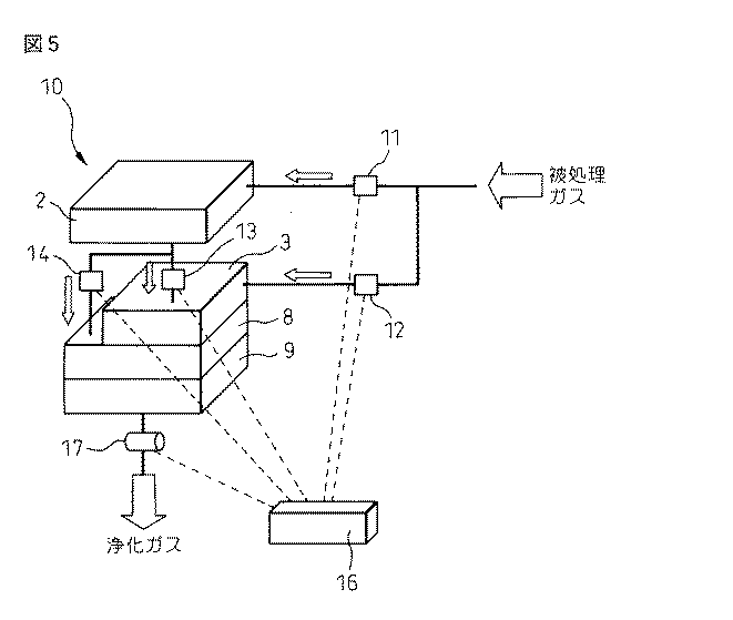
表1は、吸着開始時の吸着剤フィルタの吸着性能を示している。この表に示した各汚染物質分子は、いずれも吸着剤フィルタにより吸着保持される。表2は、吸着が進行し、飽和に近くなったときの吸着性を示している。表の一番左側の欄の化合物は吸着剤フィルタに捕捉されず、通過し始める。これらは比較的分子量の小さい化合物である。表の左から2番目と3番目の欄の化合物は、吸着されるが後に脱離して吸着剤フィルタから漏出してくることがある。表の一番右の欄の化合物は、脱着することなしに吸着剤に吸着保持されたままとなる。これらは比較的分子量の大きい化合物である。(表1,2において、D2〜D6は基本構成単位−Si(CH3)2O−がそれぞれ2〜6個のシリコーン化合物、MEKはメチルエチルケトン、IPAはイソプロピルアルコール、PGMEAはプロピレングリコールモノメチルエーテルアセテート、PGMEはプロピレングリコールモノメチルエーテル、NMPはN−メチルピロリドン、DBPはフタル酸ジブチル、DOPはフタル酸ジオクチル、TBPはリン酸トリブチルを表している。) Table 1 shows the adsorption performance of the adsorbent filter at the start of adsorption. Each contaminant molecule shown in this table is adsorbed and held by the adsorbent filter. Table 2 shows the adsorptivity when the adsorption proceeds and approaches saturation. The compounds in the leftmost column of the table are not captured by the adsorbent filter and begin to pass through. These are compounds having a relatively small molecular weight. The compounds in the second and third columns from the left of the table are adsorbed but may later desorb and leak out of the adsorbent filter. The compounds in the rightmost column of the table remain adsorbed and retained by the adsorbent without desorption. These are compounds having a relatively large molecular weight. (In Tables 1 and 2, D2 to D6 are basic structural units —Si (CH 3 ) 2 O— each having 2 to 6 silicone compounds, MEK is methyl ethyl ketone, IPA is isopropyl alcohol, PGMEA is propylene glycol monomethyl ether acetate, (PGME represents propylene glycol monomethyl ether, NMP represents N-methylpyrrolidone, DBP represents dibutyl phthalate, DOP represents dioctyl phthalate, and TBP represents tributyl phosphate.)
これらの表から明らかなとおり、比較的分子量の小さい汚染物質、すなわち低沸点の汚染物質は、吸着剤フィルタが飽和に近づくと吸着されずに通過するか、あるいは吸着、脱離を繰り返し、それにより吸着剤フィルタの吸着能力が失われやすい。これに対し、比較的分子量の大きい有機物、すなわち高沸点の汚染物質は、比較的長期間吸着を継続することができ、飽和後も脱離することが少ない。 As is clear from these tables, contaminants having a relatively low molecular weight, that is, low-boiling contaminants, pass through without being adsorbed when the adsorbent filter approaches saturation, or repeatedly adsorb and desorb, thereby The adsorption capacity of the adsorbent filter is easily lost. On the other hand, organic substances having a relatively large molecular weight, that is, contaminants having a high boiling point can continue to be adsorbed for a relatively long period of time, and are hardly desorbed even after saturation.
例えばクリーンルーム環境を保持するための環境制御装置として用いられる流体浄化装置が取り扱う被処理流体(汚染物質を含む空気)に含まれる汚染物質は、その種類と量が経時的に変動する。被処理流体が、飽和近くなると吸着剤フィルタに捕捉されにくい比較的低分子量の汚染物質と、飽和近くなっても吸着剤フィルタに捕捉される比較的高分子量の汚染物質の両方を含む場合、被処理流体を本発明に従って光触媒ユニット、吸着剤フィルタユニットの順に流すと、被処理流体中の低分子量汚染物質は光触媒により分解除去され、そのため吸着剤フィルタユニットは高分子量汚染物質を含む被処理流体を処理することができる。これにより、光触媒ユニットがなければ吸着剤フィルタユニットにやって来る、吸着剤フィルタでの吸着除去にとって必ずしも適していない低分子量汚染物質が吸着剤フィルタユニットに至ることがなくなるので、吸着剤の吸着部位の実質的に全てを、そこでの吸着除去に適した高分子量汚染物質用に当てることが可能になる。これはまた、吸着剤フィルタの有効寿命を延ばすことにも通じる。 For example, the type and amount of pollutants contained in a fluid to be treated (air containing pollutants) handled by a fluid purification device used as an environment control device for maintaining a clean room environment varies with time. If the treated fluid contains both relatively low molecular weight contaminants that are less likely to be trapped by the adsorbent filter when close to saturation and relatively high molecular weight contaminants that are trapped by the adsorbent filter even when close to saturation, When the treatment fluid is flowed in the order of the photocatalyst unit and the adsorbent filter unit in accordance with the present invention, the low molecular weight contaminants in the treated fluid are decomposed and removed by the photocatalyst, so the adsorbent filter unit removes the treated fluid containing the high molecular weight contaminants Can be processed. As a result, low molecular weight contaminants that are not necessarily suitable for adsorption removal by the adsorbent filter without the photocatalytic unit do not reach the adsorbent filter unit. In particular, all can be devoted to high molecular weight contaminants suitable for adsorption removal there. This also leads to extending the useful life of the adsorbent filter.
被処理流体が専ら低分子量の汚染物質を含む場合には、汚染物質は光触媒ユニットで分解除去され、吸着剤フィルタユニットは実質的に無負荷の運転となる。このような場合、被処理流体は光触媒ユニットでの処理後に、吸着剤フィルタユニットをバイパスさせることが可能である。 When the fluid to be treated contains exclusively low molecular weight contaminants, the contaminants are decomposed and removed by the photocatalyst unit, and the adsorbent filter unit is operated substantially without load. In such a case, the fluid to be treated can bypass the adsorbent filter unit after the treatment with the photocatalytic unit.
被処理流体が専ら高分子量汚染物質を含む場合には、汚染物質は実質的に処理されることなく光触媒ユニットを通過して吸着フィルタユニットに至り、そこで吸着除去される。このような場合には、被処理流体は光触媒ユニットをバイパスさせることが可能である。このバイパスは、光触媒ユニットがそこで分解除去できない汚染物質で汚染される可能性を排除する点で、有利である。 If the fluid to be treated contains exclusively high molecular weight contaminants, the contaminants pass through the photocatalyst unit to the adsorption filter unit without being substantially treated, and are adsorbed and removed there. In such a case, the fluid to be treated can bypass the photocatalytic unit. This bypass is advantageous in that it eliminates the possibility of the photocatalytic unit being contaminated with contaminants that cannot be resolved and removed there.
吸着フィルタユニットの下流には、除塵フィルタユニットを配置することができる。このユニットは、環境制御装置に導入される被処理流体中に最初から含まれていた微粒子状の汚染物質はもちろん、環境制御装置での処理中に生じる微粒子状の異物(例えば、吸着剤フィルタから処理中に微粒子状のゴミが発生することがある)も捕捉することにより、あらゆる種類の汚染物質を含まない清浄な流体の供給を可能にする。除塵フィルタとしては、クリーンルーム用の空気の浄化で広く使用されているHEPAフィルタ、あるいはULPAフィルタ等を用いることができる。 A dust removal filter unit can be disposed downstream of the adsorption filter unit. This unit is not limited to particulate contaminants originally contained in the fluid to be treated introduced into the environmental control device, but also particulate foreign matters (for example, from the adsorbent filter) generated during processing in the environmental control device. It also allows for the supply of clean fluids that are free from all types of contaminants. As the dust removal filter, a HEPA filter, a ULPA filter, or the like widely used in clean room air purification can be used.
本発明の流体浄化装置は、被処理流体の移送を可能にする流体移送手段を含むことができる。被処理流体が気体の場合、この手段として、ファンを使用することができる。好ましくは、このファンはユニット化して、光触媒ユニット、吸着剤フィルタユニット、そして除塵フィルタを含む場合除塵フィルタユニットと一体にされる。装置の設置条件などから、ファンはその他のユニットと分離して設置しても差し支えない。被処理流体が液の場合は、流体移送手段としてはポンプが一般に使用される。ポンプもユニット化し、そして他のユニットと一体にすることができ、あるいはそれらと分離して設置することができる。 The fluid purification apparatus of the present invention can include a fluid transfer means that enables transfer of a fluid to be processed. When the fluid to be processed is a gas, a fan can be used as this means. Preferably, the fan is unitized and integrated with the dust filter unit if it includes a photocatalyst unit, an adsorbent filter unit, and a dust filter. The fan may be installed separately from other units due to the installation conditions of the device. When the fluid to be processed is a liquid, a pump is generally used as the fluid transfer means. Pumps can also be unitized and integrated with other units or installed separately from them.
本発明の流体浄化装置においてユニット化(あるいはモジュール化)した構成機器(光触媒、吸着剤フィルタ、除塵フィルタ、流体移送手段)を用いることには、その製造、組み立てや、保守・点検が容易になるという利点がある。例えば、吸着剤フィルタユニットや除塵フィルタユニットを、フィルタエレメントを引き出し式に着脱可能なように作製することにより、フィルタエレメントの交換を容易にすることができる。 Using the component devices (photocatalyst, adsorbent filter, dust filter, fluid transfer means) unitized (or modularized) in the fluid purification apparatus of the present invention makes it easy to manufacture, assemble, maintain and inspect. There is an advantage. For example, the filter element can be easily replaced by making the adsorbent filter unit and the dust removal filter unit so that the filter element can be attached and removed in a pull-out manner.
本発明の流体浄化装置は、装置に導入する被処理流体及び装置で浄化された流体の一方又は両方の汚染物質を分析する分析器(測定モニタ)を含むこともできる。流体浄化装置への入口側に設けた分析器による分析データを使用して、先に述べた被処理流体の光触媒ユニット又は吸着剤フィルタユニットへの選択的導入のための切り換えを行うことができる。更に、流体浄化装置の出口側に設けた分析器を使用すれば、処理済みの流体中になおも汚染物質が検出された場合に流体を上流側へ戻して再処理することも可能になる。分析器としては、流体浄化装置で処理する流体に含まれることが想定される汚染物質の検出に有効な既知の分析機器を使用することができる。 The fluid purification device of the present invention can also include an analyzer (measurement monitor) that analyzes one or both of the contaminants of the fluid to be treated introduced into the device and the fluid purified by the device. Switching for selective introduction of the fluid to be treated into the photocatalyst unit or the adsorbent filter unit described above can be performed using analysis data from an analyzer provided on the inlet side to the fluid purification apparatus. Furthermore, if an analyzer provided on the outlet side of the fluid purification apparatus is used, it is possible to return the fluid to the upstream side for reprocessing when contaminants are still detected in the processed fluid. As the analyzer, a known analytical instrument that is effective for detecting a contaminant assumed to be contained in a fluid to be processed by the fluid purification device can be used.
一例として、ガスクロマトグラフィーを利用した分析を説明する。アセトン、MEKなどの低沸点の汚染物質と、DBP、DOPなどの高沸点の汚染物質を含む気体の被処理流体を、流体浄化装置の上流側、すなわち被処理流体の入口側の試料を使ってガスクロマトグラフで分析すれば、図1(a)に示したような、低沸点成分のピークと高沸点成分のピークの両方を含むガスクロマトグラムが得られ、このとき被処理流体は光触媒ユニットと吸着剤フィルタユニットの両方を通して浄化される。 As an example, analysis using gas chromatography will be described. Using a sample on the upstream side of the fluid purification device, that is, the inlet side of the fluid to be treated, containing a low-boiling contaminant such as acetone or MEK and a high-boiling contaminant such as DBP or DOP. When analyzed by gas chromatograph, a gas chromatogram including both the peak of the low boiling point component and the peak of the high boiling point component as shown in FIG. 1 (a) is obtained. At this time, the fluid to be treated is the photocatalyst unit and the adsorbent. It is purified through both filter units.
図1(b)に示したように、流体浄化装置の上流側の試料中に低沸点成分が検出された場合は、被処理流体を光触媒ユニットで処理するようにし、そして光触媒ユニットから出てきた流体は、場合により吸着剤フィルタユニットを通さずにバイパスさせてもよい。一方、図1(c)に示したように、流体浄化装置の上流側の試料中に高沸点成分が検出された場合には、被処理流体を光触媒ユニットをバイパスさせて直接吸着剤フィルタユニットに導入することが可能である。図1(d)は、流体浄化装置の出口側で得られるガスクロマトグラムを示しており、バックグラウンドの応答のみが記録され、汚染物質に対応するピークは見られない。このガスクロマトグラムに、浄化装置からの流体に汚染物質の一部が含まれることを示すピークが観測された場合には、その流体を浄化装置の上流側へ戻すこともできる。 As shown in FIG. 1 (b), when a low boiling point component is detected in the sample on the upstream side of the fluid purification device, the fluid to be treated is treated with the photocatalytic unit and comes out of the photocatalytic unit. In some cases, the fluid may be bypassed without passing through the adsorbent filter unit. On the other hand, as shown in FIG. 1 (c), when a high boiling point component is detected in the sample on the upstream side of the fluid purification device, the fluid to be treated is directly passed to the adsorbent filter unit by bypassing the photocatalytic unit. It is possible to introduce. FIG. 1 (d) shows a gas chromatogram obtained on the outlet side of the fluid purification device, in which only the background response is recorded and no peak corresponding to the contaminant is seen. When a peak indicating that a part of the contaminant is contained in the fluid from the purification device is observed in the gas chromatogram, the fluid can be returned to the upstream side of the purification device.
被処理流体あるいは処理済み流体の行き先の変更は、手動で行ってもよく、自動で行ってもよい。自動の場合には、分析器からの信号を処理して変更を自動的に行う信号を発生する制御ユニットを使用することができる。 The change of the destination of the fluid to be processed or the processed fluid may be performed manually or automatically. In the automatic case, a control unit can be used that processes the signal from the analyzer and generates a signal that automatically changes.
次に、本発明の流体浄化装置を図面を参照して更に説明するが、本発明はそれらに限定されるものではない。 Next, although the fluid purification apparatus of this invention is further demonstrated with reference to drawings, this invention is not limited to them.
図2は、本発明の流体浄化装置で使用する光触媒ユニット2と吸着剤フィルタユニット3の組み合わせを示す概略図である。被処理流体としては、例えば、クリーンルーム内の空気に代表される気体を用いることができ、あるいは半導体デバイス生産設備で使用した純水を用いてもよい。被処理流体は、光触媒ユニット2、吸着剤フィルタ3の順番でこの組み合わせを通過する。
FIG. 2 is a schematic view showing a combination of the
光触媒ユニット2には、150〜450nmの波長帯の紫外線ランプ、又は放電に伴う発光体4と、ガラス材料等の支持体表面上に担持したTiO2などの光触媒5が含まれており、このユニットは、例えば特開2001−62253号明細書に示されたような構造を持つものとして製作することができる。
The
吸着剤フィルタユニット3は、例えば活性炭、活性炭に添着した中和反応体、あるいはイオン交換繊維等のイオン交換基のような、被処理流体中の汚染物質の吸着除去に適した吸着フィルタを使って製作される。 The adsorbent filter unit 3 uses an adsorbent filter suitable for adsorbing and removing contaminants in the fluid to be treated, such as activated carbon, a neutralized reactant attached to the activated carbon, or an ion exchange group such as an ion exchange fiber. Produced.
この組み合わせを使って、無機系もしくは有機系ガス、オゾンガス等の汚染物質を除去することができる。 This combination can be used to remove contaminants such as inorganic or organic gases and ozone gas.
吸着剤フィルタは、通常は活性炭をベースにしており、吸着量の増大に伴い、例えばアセトン、メタノール、エタノールのような比較的分子量の小さい有機物、すなわち低沸点の有機物から捕捉能力を失っていく傾向にある。例えば中和反応体を添着したような吸着剤フィルタは、吸着量の増大に伴い、吸着剤フィルタが飽和される前に、アセトン、メタノール、エタノールのような分子量の小さい有機物を吸着することができなくなり、これらの物質は吸着剤フィルタユニットを通過してしまうようになる。それらよりやや分子量の大きい、酢酸、蟻酸、イソプロピルアルコール(IPA)のような有機物は、吸着した後に脱離する可能性がある。そのため、これらの比較的分子量の小さい有機物は吸着剤フィルタで完全に除去するのにそれほど適しているとは言えない。 Adsorbent filters are usually based on activated carbon and tend to lose their ability to capture from relatively low molecular weight organics such as acetone, methanol, ethanol, etc. It is in. For example, an adsorbent filter with a neutralization reactant attached can adsorb organic substances with a low molecular weight such as acetone, methanol, and ethanol before the adsorbent filter is saturated as the adsorption amount increases. As a result, these substances pass through the adsorbent filter unit. Organic substances such as acetic acid, formic acid, and isopropyl alcohol (IPA), which have a slightly higher molecular weight than these, may be desorbed after being adsorbed. Therefore, it cannot be said that these relatively low molecular weight organic substances are so suitable for complete removal with an adsorbent filter.
一方で光触媒ユニット2は、光触媒作用によって汚染物質を分解するものであり、例えばアセトン、メタノール、エタノールのような分子量の小さい有機物、すなわち低沸点の有機物の分解に優れているが、例えばキシレン、エチルベンゼン、のような比較的分子量の大きい有機物、すなわち高沸点の有機物の分解には、分解効率の面で問題がある。
On the other hand, the
そこで、被処理流体中の例えばアセトン、メタノール、エタノールのような分子量の小さい有機物、及びこれらよりもやや分子量の大きい酢酸、蟻酸、イソプロピルアルコールのような有機物を、まず光触媒ユニット2で分解、除去し、次に吸着剤フィルタユニット3で、光触媒ユニット2で分解、除去できなかった例えばキシレン、エチルベンゼン、シクロヘキサノンのような比較的分子量の大きい有機物を吸着、除去することにより、様々な汚染物質を含む被処理流体を効率よく処理して浄化することができる。また、吸着剤フィルタユニット3を比較的分子量の大きい汚染物質の吸着除去に専念させることができることから、吸着剤フィルタの吸着能力を長く維持することができる。
Therefore, for example, organic substances having a small molecular weight such as acetone, methanol, and ethanol, and organic substances such as acetic acid, formic acid, and isopropyl alcohol having a slightly higher molecular weight than these are first decomposed and removed by the
光触媒ユニット2と吸着剤フィルタユニット3を効果的に働かせる運転条件は、それらで用いる光触媒と吸着剤フィルタのタイプに依存して決定することができる。
The operating conditions for effectively operating the
図3に、図2に示した光触媒ユニット2と吸着剤フィルタユニット3の組み合わせを取り入れた本発明の流体浄化装置の一態様を示す。
この態様の装置1は、光触媒ユニット2、吸着剤フィルタユニット3、流体移送手段のユニット8、及び除塵フィルタユニット9をこの順に配列し一体化して構成されており、被処理流体が光触媒ユニット2側から装置1に入り、浄化された流体が除塵フィルタユニット9から出てゆく。このような装置1は、例えば、クリーンルームの壁面又は天井面等、あるいは半導体デバイスなどの生産設備の壁面又は天井面等に設けられ、被処理流体としてのクリーンルーム内の空気を清浄にするのに使用することができる。設置場所の制約により各ユニットを一体化するのが困難な場合などには、それらを隣接せずに離して設置することも可能である。
FIG. 3 shows an embodiment of the fluid purification device of the present invention that incorporates the combination of the
The
図3に示した装置1において、ユニット8の流体移送手段としては、被処理流体が気体の場合はファンを、被処理流体が液体の場合はポンプを使用することができる。流体移送手段がファンの場合のユニット8は、図に示した吸着剤フィルタ3と除塵フィルタ9の間に限らず、例えば光触媒ユニット2の上流側に配置してもよく、ユニット8以外のユニット2、3、9の組み合わせと切り離した位置に配置することも可能である。この場合も、流体移送手段のユニット8は、例えば、光触媒ユニット2の上流側に接続するように、あるいは吸い込み側が吸着剤フィルタユニット3の出口側に接続し、そして吐出側が除塵フィルタの入口側に接続するようにすることが可能である。流体移送手段がポンプの場合のユニット8も、任意の位置に配置することができるが、好ましくは光触媒ユニット2の上流側に配置される。被処理流体が気体の場合も液体の場合も、流体移送手段が潜在的汚染源となるので、ユニット8は除塵フィルタユニット9の上流側に設置するのが好ましい。
In the
図4(a)〜4(c)に、本発明の流体浄化装置1を環境制御装置として使用する場合の、浄化装置1と制御しようとする環境との位置関係の代表的なものを例示する。図4(a)は、浄化装置1を閉鎖系製造装置又は作業ブース11の天井部に設置した例であり、浄化装置1で浄化した空気を送り込むことにより製造装置又は作業ブース11内の作業環境を清浄な状態に保つことができる。図4(b)は、浄化装置1を閉鎖系製造装置又は作業ブース11に隣接して設置した例であり、やはり製造装置又は作業ブース11内の作業環境を清浄な状態に保つのに使用することができる。この例は、製造装置又は作業ブース11の天井部に浄化装置1を設置するスペースがない場合に採用することができ、場合によっては浄化装置1を製造装置又は作業ブース11の壁に直結して設置することも可能である。図4(a)と4(b)の例において、製造装置又は作業ブース11をクリーンルームに替えれば、クリーンルームの作業環境の制御が可能になる。図4(c)は、クリーンルーム内の製造装置又は作業ブース11からの排気系に浄化装置1を取り入れた例であり、製造装置又は作業ブース11からの排気中に含まれる汚染物質を除去することでクリーンルームの二次汚染を防止するのに使用することができる。この場合には、クリーンルーム内の作業環境を清浄に制御することになり、そしてその結果として、製造装置又は作業ブース11自体への清浄空気の供給のために図4(a)又は4(b)に示したように設置される別の浄化装置(図示せず)の効率の向上、あるいは特に吸着剤フィルタユニットの長寿命化に寄与することができる。
4 (a) to 4 (c) exemplify a representative positional relationship between the
本発明の浄化装置を、ウエハなどの搬送のために局所クリーン保管部が必要な搬送台車に設置し、そしてこの台車を、これまでボックス搬送手段が一般的であったウエハ等の搬送手段の代わりに使用することも可能である。 The purifying apparatus of the present invention is installed in a transport cart that requires a local clean storage unit for transporting wafers and the like, and this cart is replaced with a transport device for wafers and the like, which has conventionally been a box transport means. It can also be used.
図5は、先の例で説明した光触媒ユニット2、吸着剤フィルタユニット3、ファンから構成される流体移送用のユニット8、除塵フィルタ9に加えて、被処理ガスの汚染物質濃度測定モニタ15、被処理ガスの流動経路を切り換えるためのバルブ11、12、13、14、そして汚染物質濃度に応じてバルブを切り換えるための制御部16で構成されている、クリーンルームの環境制御に使用することが可能な本発明の流体浄化装置10を示している。この場合の非処理ガスは、汚染物質を含有している可能性のある空気である。
FIG. 5 shows, in addition to the
例えば、汚染物質濃度測定モニタ15、17として、クリーンルーム内での有機物による汚染の原因と考えられている、やや分子量の小さい有機物のIPAと、比較的分子量の大きい有機物のシクロヘキサノンの量を測定するモニタを使用する。 For example, as the pollutant concentration measurement monitors 15 and 17, monitors that measure the amount of organic matter IPA, which is considered to be the cause of contamination by organic matter in a clean room, and organic matter cyclohexanone having a relatively small molecular weight. Is used.
クリーンルームに導入される被処理ガスの空気中にIPAの含まれることが汚染物質濃度測定モニタ15で検出される場合は、制御部16からの信号によりバルブ11が開き、バルブ12が閉じて、光触媒ユニット2でIPAを分解、除去する。光触媒ユニット2でIPAを除去したガスは、やはり制御部16からの信号によりバルブ13を閉じ、バルブ14を開いて吸着剤フィルタユニット3をバイパスすることができる。IPAを除去したガスは、次いで流体移送用のユニット8により除塵フィルタ9を通してクリーンルーム内へ供給される。
When the pollutant concentration measurement monitor 15 detects that IPA is contained in the air of the gas to be treated introduced into the clean room, the
被処理ガスの空気中にIPAが検出されず、シクロヘキサノンが検出される場合は、制御部16からの信号によりバルブ11を閉じ、バルブ12を開いてガスを光触媒ユニット2をバイパスさせて吸着剤フィルタユニット3へ直接送り、吸着剤フィルタによりシクロヘキサノンを吸着、除去する。
When IPA is not detected in the air of the gas to be treated and cyclohexanone is detected, the
被処理ガスの吸気中にIPAとシクロヘキサノンの両方が検出される場合は、バルブ11、13が開き、バルブ12、14が閉じて、IPAを光触媒ユニット2で分解、除去した後、シクロヘキサノンを吸着剤フィルタユニット3で吸着、除去する。
When both IPA and cyclohexanone are detected during the intake of the gas to be treated, the
光触媒ユニット2は、光触媒での分解、除去に適した分子量の小さい有機物が被処理ガス中に含まれている場合に、バルブ11を開いて被処理ガスを受け取り、そうでない場合はバルブ11を閉じて被処理ガスをバイパスさせることができるため、励起光源の紫外線ランプ又は放電に伴う発光体の長寿命化に寄与するとともに、その定期的な洗浄又は交換回数を減らすことができる。同様に、支持体に担持した光触媒の定期的な洗浄又は交換回数を減らすこともできる。
The
吸着剤フィルタユニット3は、常に分子量の小さい有機物のないガスを受け取り、またこのユニットで処理すべき分子量の大きい有機物がないガスをバイパスさせることもできるため、やはり吸着剤フィルタ3の長寿命化及び吸着剤フィルタの交換回数の減少を実現することができる。 Since the adsorbent filter unit 3 can always receive a gas without an organic substance having a low molecular weight, and can bypass a gas without an organic substance having a high molecular weight to be processed by this unit, the life of the adsorbent filter 3 can be increased. A reduction in the number of replacements of the adsorbent filter can be realized.
汚染物質濃度測定モニタ15の測定結果によるバルブ11、12、13、14の開閉制御は、制御部16を使用せずに、手動で行ってもよい。
The opening / closing control of the
更に、浄化装置1の出口側に汚染物質濃度測定モニタ17を追加して設置することも可能である。出口側の測定モニタ17は、光触媒ユニット2又は吸着剤フィルタユニット3の寿命を確認する手段として有効であり、有機物が多く検出される場合は、検出される有機物の種類に応じて、光触媒ユニット2又は吸着剤フィルタユニット3が劣化したと判断することができる。このモニタ17の測定結果を、バルブ11、12、13、14の制御によるガス流動経路の変更に反映することも可能である。あるいは、浄化装置1の入口側の汚染物質濃度測定モニタ15を省き、出口側の測定モニタ17のみを設けることも可能である。
Furthermore, it is possible to additionally install a pollutant concentration measurement monitor 17 on the outlet side of the
オゾンガスの測定が可能な汚染物質濃度測定モニタ17を用いることにより、浄化装置10をオゾンを含むガスの浄化に利用することもできる。オゾンは半導体ウエハ表面を酸化してしまうため、効率よく除去する必要がある。オゾンは、吸着剤フィルタ3により酸素に還元して除去される。しかし、光触媒はどちらかと言えば酸化剤として機能するため、オゾンの発生に加担することはあっても、その除去に寄与することはできない。そこで、汚染物質濃度測定モニタ15、17でオゾンガスが検出された場合は、バルブ11、13、14を閉じて、バルブ12を開ける。オゾンを含むガスは光触媒ユニット2をバイパスして吸着剤フィルタユニット3に流れるため、効率よくオゾンを除去することができる。
By using the pollutant concentration measurement monitor 17 capable of measuring ozone gas, the
汚染物質濃度測定モニタ15、17として、有機物の総量を測定するモニタを使用し、その測定結果に基づいてガスの流動経路を変更するようにしてもよい。これは、例えば、通常の被処理ガス中の汚染物質の種類と量が決まっていて、それ以外の汚染物質として光触媒での処理が有効な物質が被処理ガス中に時折含まれることがあるような場合に、特に有効である。 Monitors that measure the total amount of organic substances may be used as the pollutant concentration measurement monitors 15 and 17, and the gas flow path may be changed based on the measurement results. This is because, for example, the type and amount of pollutants in a normal gas to be treated are determined, and as the other pollutants, substances that can be effectively treated with a photocatalyst are occasionally included in the gas to be treated. It is particularly effective in such cases.
汚染物質濃度測定モニタ15、17は、被処理ガス中の汚染物質の種類と量の変動が予測されるときのような、必要時に設置するようにしてもよい。また、汚染物質濃度測定モニタ15、17をガスの流動経路中に設けずに他の場所に設置し、ガス流動経路から採取したサンプルを他の場所に設置した測定モニタで測定してもよい。 The pollutant concentration measurement monitors 15 and 17 may be installed when necessary, such as when fluctuations in the type and amount of pollutants in the gas to be treated are predicted. Further, the pollutant concentration measurement monitors 15 and 17 may be installed in another place without being provided in the gas flow path, and a sample collected from the gas flow path may be measured by a measurement monitor installed in another place.
更に、バルブ11、12、13、14の代わりに、ダンパーやスリット式の開閉シャッターを用いることも可能である。また、バルブ13、14はなくてもよく、バルブ11、12の切り換えのみでも同様な効果は期待できる。
Furthermore, a damper or a slit-type opening / closing shutter can be used in place of the
流体浄化装置10を多段に設置することで、更に効率的な浄化を行うことも可能である。また、流体浄化装置10自体を、例えばステンレスの箱に入れると、より効率的な浄化が可能になる。
By installing the
図6は、図5を参照して説明した流体浄化装置10に、除塵フィルタユニット9の出口側から流体浄化装置の上流側への循環経路と、この循環経路への切り換え用のバルブ18、19とを追加した態様の流体浄化装置10’を示している。この浄化装置10’を使用して種々の汚染物質を含むガスを浄化する例を、以下で説明する。
FIG. 6 shows a flow path from the outlet side of the
最初の例は、半導体デバイスの製造においてシリコンウエハの酸化の原因になる酢酸、蟻酸などの汚染物質を含む空気を被処理ガスとして使用し、汚染物質の総量(TOC)を測定する水晶振動子型膜厚モニタを汚染物質濃度測定モニタ15、17として使用する。各バルブ11、12、13、14、18、19の切り換えは、TOCの測定結果に基づき、制御部16からの信号により自動で行う。
The first example is a crystal oscillator type that uses air containing contaminants such as acetic acid and formic acid, which cause oxidation of silicon wafers in the manufacture of semiconductor devices, as the gas to be processed, and measures the total amount of contaminants (TOC). The film thickness monitor is used as the pollutant concentration measurement monitor 15 or 17. Switching of each
水晶振動子型膜厚モニタ15で被処理ガスの汚染物濃度を測定する。汚染物濃度が低いときは、バルブ11、14を開き、バルブ12、13を閉じて、光触媒ユニット2でガスを浄化する。通常、浄化装置10’の出口側のバルブ18は開き、循環経路のバルブ19は閉じておく。汚染物濃度が中レベルの時は、バルブ11を閉じ、バルブ12を開いて、吸着剤フィルタユニット3でガスを浄化する。汚染物濃度が高いときは、バルブ11、13を開き、バルブ12、14を閉じて、光触媒ユニット2と吸着剤フィルタユニット3の両方でガスを浄化する。
The contaminant concentration of the gas to be processed is measured by the crystal oscillator type
水晶振動子型膜厚モニタ17で浄化ガスの汚染物濃度を監視する。光触媒ユニット2のみでガスを浄化していてモニタ17で汚染物質が検出されたときは、バルブ13を開き、バルブ14を閉じて、光触媒ユニット2と吸着剤フィルタユニット3の両方でガスを浄化するように浄化装置10’の運転を切り換える。吸着剤フィルタユニット3のみでガスを浄化していて汚染物が検出されたときは、バルブ11、13を開き、バルブ12、14を閉じて、やはり光触媒ユニット2と吸着剤フィルタユニット3の両方でガスを浄化するように運転を切り換える。光触媒ユニット2と吸着剤フィルタユニット3の両方でガスを浄化していて汚染物質が検出されたときは、バルブ18を閉じ、バルブ19を開いてガスを循環させ、再度浄化を行う。
The contaminant concentration of the purified gas is monitored by the crystal oscillator type
2番目の例は、被処理ガス中の汚染物質としてのNOx、SOx、オゾンを除去する。測定モニタ15、17に、除去しようとするNOx、SOx又はオゾンを測定するためのモニタを使用する。除去対象の汚染物質が2以上の場合は、各汚染物質用の測定モニタを用意する。 The second example removes NO x , SO x , and ozone as pollutants in the gas to be treated. As the measurement monitors 15 and 17, a monitor for measuring NO x , SO x or ozone to be removed is used. If there are two or more contaminants to be removed, a measurement monitor for each contaminant is prepared.
測定モニタ15で被処理ガスの汚染物濃度を測定する。汚染物濃度が高いときは、バルブ11を閉じ、バルブ12を開いて、吸着剤フィルタユニット3でガスを浄化する。汚染物濃度が低いときは、バルブ11、14を開き、バルブ12、13を閉じて、光触媒ユニット2でガスを浄化する。通常、浄化装置10’の出口側のバルブ18は開き、バルブ19は閉じておく。
The measurement monitor 15 measures the contaminant concentration of the gas to be processed. When the contaminant concentration is high, the
測定モニタ17で浄化ガスの汚染物濃度を監視する。光触媒ユニット2のみでガスを浄化していて測定モニタ17で汚染物が検出されたときは、バルブ13を開き、バルブ14を閉じて、光触媒ユニット2と吸着剤フィルタユニット3の両方でガスを浄化するよう、浄化装置10’の運転を切り換える。吸着剤フィルタユニット3のみでガスを浄化していて汚染物が検出されたときは、バルブ11、13を開き、バルブ12、14を閉じて、やはり光触媒ユニット2と吸着剤フィルタユニット3の両方でガスを浄化するように運転を切り換える。光触媒ユニット2と吸着剤フィルタユニット3の両方でガスを浄化していて汚染物が検出されたときは、バルブ18を閉じ、バルブ19を開いてガスを循環させ、再度浄化処理する。
The contaminant concentration of the purified gas is monitored by the
3番目の例は、アンモニアの除去によりガスを浄化する。測定モニタ15、17に、アンモニア測定モニタを使用する。 The third example purifies the gas by removing ammonia. As the measurement monitors 15 and 17, an ammonia measurement monitor is used.
測定モニタ15で被処理ガスのアンモニア濃度を測定する。アンモニア濃度が高いときは、バルブ11、13を開き、バルブ12、14を閉じて、光触媒ユニット2と吸着剤フィルタユニット3の両方でガスを浄化する。アンモニア濃度が低いときは、バルブ11、14を開き、バルブ12、13を閉じて光触媒ユニット2でガスを浄化するか、あるいはバルブ11、14を閉じ、バルブ12を開いて吸着剤フィルタユニット3で浄化する。通常、浄化装置10’の出口側のバルブ18は開き、バルブ19は閉じておく。
The ammonia concentration of the gas to be processed is measured by the
測定モニタ17で浄化ガスのアンモニア濃度を監視する。アンモニアが検出されたときは、バルブ18を閉じ、バルブ19を開いてガスを循環させ、ガスを再度浄化処理する。光触媒ユニット2か吸着剤フィルタユニット3のどちらかのみで浄化を行っていた場合は、ガスを循環させてもよく、あるいは運転を停止していた方のユニットも稼働するようにバルブを切り換えてもよく、あるいはガスを循環させ且つ停止していた方のユニットを稼働するようにしてもよい。
The ammonia concentration of the purified gas is monitored by the
図7は、図6を参照して説明した流体浄化装置10’の各バルブ11、12、13、14、18、19の切り換えを手動で行う例を示している。この図の流体浄化装置10”では、測定モニタ15、17に、ガスの吸着管であるTENAX管を使用する。吸着した有機物ガスをTENAX管から脱着してガスクロマトグラフにより定性、定量分析し、その結果に基づき、各バルブを手動操作する。
FIG. 7 shows an example in which the
分析の結果、分子量の小さい有機物ガスが多いときは、バルブ11、14を開き、バルブ12、13を閉じて、光触媒ユニット2のみでガスを浄化する。分子量の大きい有機物ガスが多いときは、バルブ11を閉じ、バルブ12を開いて、吸着剤フィルタユニット3のみでガスを浄化する。通常、浄化装置10”の出口側のバルブ18は開き、循環経路のバルブ19は閉じておく。
As a result of analysis, when the organic gas having a small molecular weight is large, the
測定モニタ17で浄化ガスの有機物ガス濃度を監視する。有機物ガスが検出されたときは、バルブ11、13を開き、バルブ12、14を閉じて、光触媒ユニット2と吸着剤フィルタユニット3の両方でガスを浄化する。光触媒ユニット2と吸着剤フィルタユニット3の両方でガスを浄化していて、測定モニタ17で分子量の小さい有機物ガスが検出されるときは、光触媒が寿命に達し、分子量の大きい有機物ガスが検出されるときは、吸着剤フィルタが寿命に達していると見なされ、寿命に達したものを交換する。この交換時には、バルブ18を閉じ、バルブ19を開き、正常である(交換しない)方の光触媒ユニット2又は吸着剤フィルタ3を通してガスを循環させるよう、バルブ11〜14を切り換える。
A measurement monitor 17 monitors the organic gas concentration of the purified gas. When the organic gas is detected, the
被処理ガスの流動経路を切り換えて運転する図5〜7の流体浄化装置10、10’、10”において、除塵フィルタユニット9は吸着フィルタユニット3の下流側に配置されているが、これは必ずしも吸着剤フィルタユニット3の下流側に位置する必要はない。例えば、被処理ガスの流動経路切り換え用にバルブ11、12で分岐する前の被処理ガス流路に同様の機能の除塵フィルタが設けられている場合には、この除塵フィルタを図5〜7における除塵フィルタ9の代わりに利用してもよい。同様に、図5〜7の流体浄化装置10、10’、10”では流体移送用のユニット8は吸着フィルタユニット3と除塵フィルタ9との間に配置されているが、このユニット8の位置はこれに限定されず、例えば、被処理ガスの流動経路切り換え用にバルブ11、12で分岐する前の被処理ガス流路に配置することも可能である。
In the
既に述べたように、本発明の流体浄化装置では、分子量の小さい、低沸点の有機物の分解除去に優れた光触媒ユニットを第1段に配置し、分子量の大きい、高沸点の有機物の吸着除去に優れた吸着剤フィルタを第2段に配置している。図5〜7を参照して説明したように、本発明の流体浄化装置では被処理流体中の汚染物質の種類に応じてどちらかのユニット又は両方のユニットを使って流体の浄化を行うことができるが、被処理流体中の汚染物質の種類にかかわらず、最初は、低分子量、低沸点の有機物の吸着除去もできる吸着剤フィルタユニットにもっぱら被処理ガスを導入するようにしてもよい。浄化が進行し、吸着剤フィルタが飽和に近づくと、低分子量の有機物は吸着剤フィルタを通過し始め、浄化装置の出口側に設けられた測定モニタで検出され始める。この時点で、被処理流体の流動経路を変更して光触媒ユニットから導入するようにし、そこで低分子量の有機物を分解除去したガスを吸着剤フィルタユニットに供給することができる。こうして吸着剤フィルタユニットには分子量の大きい有機物が供給されるため、飽和に近づいた吸着剤フィルタでのガスの浄化を更に継続することが可能になる。 As already described, in the fluid purification device of the present invention, a photocatalytic unit having a small molecular weight and excellent in decomposing and removing low-boiling organic substances is arranged in the first stage to adsorb and remove high-boiling organic substances having a large molecular weight. An excellent adsorbent filter is placed in the second stage. As described with reference to FIGS. 5 to 7, in the fluid purification apparatus of the present invention, the fluid can be purified by using either unit or both units according to the type of contaminant in the fluid to be treated. However, regardless of the type of contaminant in the fluid to be treated, first, the gas to be treated may be introduced exclusively into the adsorbent filter unit that can adsorb and remove organic substances having a low molecular weight and a low boiling point. As purification proceeds and the adsorbent filter approaches saturation, low molecular weight organic matter begins to pass through the adsorbent filter and begins to be detected by a measurement monitor provided on the outlet side of the purification device. At this time, the flow path of the fluid to be treated is changed to be introduced from the photocatalyst unit, and the gas obtained by decomposing and removing the low molecular weight organic substance can be supplied to the adsorbent filter unit. Since the organic substance having a large molecular weight is supplied to the adsorbent filter unit in this way, it is possible to further continue the purification of the gas in the adsorbent filter approaching saturation.
あるいはまた、被処理流体の流動経路の変更を行わず、被処理流体を常に光触媒ユニット、吸着剤フィルタユニットの順に浄化処理することも可能である。この場合にも、光触媒ユニットで低分子量の有機物が分解除去されたガスが吸着剤フィルタユニットに供給されるため、吸着剤フィルタの最大限の能力を有効利用することができる。 Alternatively, it is possible to always purify the fluid to be treated in the order of the photocatalyst unit and the adsorbent filter unit without changing the flow path of the fluid to be treated. Also in this case, since the gas from which the low molecular weight organic substances are decomposed and removed by the photocatalyst unit is supplied to the adsorbent filter unit, the maximum capacity of the adsorbent filter can be effectively used.
本発明の流体浄化装置には、図8に示したように、チラー等を利用した恒温・恒湿ユニット22を付加することも可能である。この図に示した流体浄化装置21は、恒温・恒湿ユニット22を光触媒ユニット2の手前に含むことを除き、図5〜7を参照して説明した流体浄化装置10、10’、10”と同様に構成することができ、図8に示した参照符号で図5〜7で用いたのと同じものはそれらに示したのと同じユニットを示している。図8の装置は、もちろんながら、図5〜7に示されていてこの図に示されていない機器(バルブ、測定モニタ、制御部)を含むこともできる。ユニットを分離して配置可能なこと、流体移送手段8の位置の変更が可能なことも、先に説明した浄化装置10、10’、10”の場合と同様である。
As shown in FIG. 8, a constant temperature /
恒温・恒湿ユニット22を用いることにより、それに続く光触媒ユニット2、吸着剤フィルタユニット3でのガスの浄化に最適な条件のガスを供給することができる。
By using the constant temperature /
また、図8に示した恒温・恒湿ユニット22を備えた流体浄化装置も、ウエハなどの搬送のために局所クリーン保管部が必要な搬送台車に設置し、この台車をこれまでボックス搬送手段が一般的であったウエハ等の搬送手段の代わりに使用することができる。
Further, the fluid purification apparatus having the constant temperature /
図9に、本発明の流体浄化装置31をクリーンブース30内の環境制御のために用いた例を示す。この流体浄化装置31も、図5〜7を参照して説明した流体浄化装置10、10’、10”と同様に構成することができ、図9に示した参照符号で図5〜7で用いたのと同じものはそれらに示したのと同じ構成要素を示している。図8の装置も、図5〜7に示されていてこの図に示されていない構成要素(バルブ、制御部)を含むことができる。ユニットを分離して配置可能なこと、流体移送手段8の位置の変更が可能なことも、先の浄化装置10、10’、10”の場合と同様である。
In FIG. 9, the example which used the
外気を導入して浄化装置31で処理した浄化空気をクリーンブース30へ供給する。クリーンブース30内の空気の浄化効率を高めるため、浄化装置31で処理するガス量のうちの、例えば90%を、循環流路33によりクリーンブース30から取り出し、浄化装置31へ導入する外気と一緒にしてもよい。この循環により、浄化装置31の浄化効率を上げることができる(浄化装置31からクリーンブース30へ供給される清浄空気と同じ空気が循環するとし、その循環量を浄化装置31の処理ガス量の90%とすれば、浄化装置31の浄化効率は10倍向上することになる)。
Purified air that has been treated by the
更に、浄化装置31の手前に、図8を参照して説明したような恒温・恒湿ユニットを設けることも可能である。 Furthermore, a constant temperature / humidity unit as described with reference to FIG.
図10に、本発明の流体浄化装置41をSMIF−ボックス42の開口部40の環境制御のために用いた例を示す。この流体浄化装置41も、図5〜7を参照して説明した流体浄化装置10、10’、10”と同様に構成することができ、図10に示した参照符号で図5〜7で用いたのと同じものはそれらに示したのと同じ構成要素を示している。図10の装置も、図5〜7に示されていてこの図に示されていない構成要素(バルブ、制御部)を含むことができる。ユニットを分離して配置可能なこと、流体移送手段8の位置の変更が可能なことも、先の浄化装置10、10’、10”の場合と同様である。
In FIG. 10, the example which used the
SMIF−ボックス42の開口部40は、デバイス製造過程のウエハ48などをSMIF−ボックス42より自動で出し入れする部分であり、その環境浄化は、SMIF−ボックス42の開閉時にのみ必要とされる。この必要時に、浄化装置41からの浄化空気をSMIF−ボックス開口部40へ供給し、供給不要時には、循環流路43により全量を浄化装置41へ戻し、循環させる。この切り換えは、図示しないバルブで行うことができる。
The
本発明は、以上説明したとおりであるが、その特徴を種々の態様とともに付記すれば、次のとおりである。
(付記1)被処理流体から汚染物質を除去してそれを浄化する装置であって、被処理流体中の汚染物質を分解可能な光触媒及びこの光触媒を励起するための励起光源を有する光触媒ユニットと、被処理流体中の汚染物質を吸着し得る吸着剤フィルタユニットとを含み、被処理流体の流動方向に対し光触媒ユニットを吸着剤フィルタユニットの上流側に配置し、且つ更に、吸着剤フィルタユニットの下流側に配置した除塵フィルタユニットを含むことを特徴とする流体浄化装置。
(付記2)前記被処理流体を前記光触媒ユニット又は前記吸着剤ユニットへ選択的に導入する切り換え手段を更に含む、付記1記載の流体浄化装置。
(付記3)被処理流体から汚染物質を除去してそれを浄化する装置であって、被処理流体中の汚染物質を分解可能な光触媒及びこの光触媒を励起するための励起光源を有する光触媒ユニットと、被処理流体中の汚染物質を吸着し得る吸着剤フィルタユニットとを含み、被処理流体の流動方向に対し光触媒ユニットを吸着剤フィルタユニットの上流側に配置し、且つ更に、被処理流体を光触媒ユニット又は吸着剤ユニットへ選択的に導入する切り換え手段を含むことを特徴とする流体浄化装置。
(付記4)前記被処理流体が前記光触媒ユニットでの光触媒作用による除去に適した汚染物質を含むとき、当該被処理流体を前記光触媒ユニットに導入し、前記被処理流体が前記吸着剤ユニットでの吸着による除去に適した汚染物質を含むとき、当該被処理流体を吸着剤フィルタユニットに導入する、付記2又は3記載の流体浄化装置。
(付記5)前記被処理流体が前記光触媒ユニットでの光触媒作用による除去に適した汚染物質を含むとき、前記光触媒ユニットで処理したガスに前記吸着剤ユニットをバイパスさせる、付記4記載の流体浄化装置。
(付記6)前記被処理流体中の汚染物質の濃度が低いときはそれを選択的に前記光触媒ユニットで浄化し、前記被処理流体中の汚染物質の濃度が中レベルのときはそれを選択的に前記吸着剤フィルタユニットで浄化し、前記被処理流体中の汚染物質の濃度が高いときは前記光触媒ユニットと前記吸着剤フィルタユニットの両方でそれを浄化する、付記2又は3記載の流体浄化装置。
(付記7)浄化した流体中に前記汚染物質が検出された場合において、前記被処理流体を選択的に前記光触媒ユニットで浄化していたときは前記吸着剤フィルタユニットでも当該被処理流体を浄化するよう当該流体浄化装置の運転を切り換え、前記被処理流体を選択的に前記吸着剤フィルタユニットで浄化していたときは前記光触媒ユニットでも当該被処理ガスを浄化するよう当該流体浄化装置の運転を切り換え、前記光触媒ユニットと前記吸着剤フィルタユニットの両方で前記被処理流体を浄化していたときは当該流体を循環させて当該流体浄化装置において再度浄化処理する、付記6記載の流体浄化装置。
(付記8)当該流体浄化装置で除去しようとする汚染物質が1種類であり、前記被処理流体中の当該汚染物質の濃度が高いときは前記光触媒ユニットと前記吸着剤フィルタユニットの両方で当該被処理流体を浄化し、当該汚染物質の濃度が低いときは前記光触媒ユニットと前記吸着剤フィルタユニットのどちらか一方で当該被処理流体を浄化する、付記2又は3記載の流体浄化装置。
(付記9)前記光触媒ユニットと前記吸着剤フィルタユニットの両方で浄化を行っていた場合において、前記浄化を受けた被処理流体中に前記汚染物質が検出されたとき、当該被処理流体を循環させる、付記8記載の流体浄化装置。
(付記10)前記光触媒ユニットと前記吸着剤フィルタユニットのどちらか一方で浄化を行っていた場合において、当該浄化を受けた被処理流体中に前記汚染物質が検出されたとき、当該被処理流体を循環させるか、浄化を行っていなかった方のユニットも浄化に使用するか、あるいは当該被処理流体を循環させて且つ浄化を行っていなかった方のユニットも浄化に使用する、付記8記載の流体浄化装置。
(付記11)前記切り換え手段が自動式の手段である、付記2又は3記載の流体浄化装置。
(付記12)前記切り換え手段が手動式の手段である、付記2又は3記載の流体浄化装置。
(付記13)前記被処理流体を移送するための流体移送手段を更に含む、付記2記載の流体浄化手段。
(付記14)前記流体移送手段が前記吸着剤フィルタユニットと前記除塵フィルタユニットとの間に位置する、付記13記載の流体浄化装置。
(付記15)前記被処理流体を移送するための流体移送手段を更に含む、付記3記載の流体浄化手段。
(付記16)前記吸着剤フィルタユニットの下流側に配置した除塵フィルタユニットを更に含み、且つ、前記流体移送手段が前記吸着剤フィルタユニットと当該除塵フィルタユニットとの間に位置している、付記15記載の流体浄化装置。
The present invention is as described above. The features of the present invention will be described as follows together with various aspects.
(Appendix 1) An apparatus for removing contaminants from a fluid to be treated and purifying it, a photocatalyst capable of decomposing contaminants in the fluid to be treated, and a photocatalytic unit having an excitation light source for exciting the photocatalyst An adsorbent filter unit capable of adsorbing contaminants in the fluid to be treated, a photocatalytic unit disposed upstream of the adsorbent filter unit with respect to the flow direction of the fluid to be treated, and A fluid purification device comprising a dust removal filter unit disposed on the downstream side.
(Supplementary note 2) The fluid purification device according to
(Appendix 3) An apparatus for removing a contaminant from a fluid to be treated and purifying it, a photocatalyst capable of decomposing the contaminant in the fluid to be treated, and a photocatalytic unit having an excitation light source for exciting the photocatalyst An adsorbent filter unit capable of adsorbing contaminants in the fluid to be treated, a photocatalytic unit disposed upstream of the adsorbent filter unit in the flow direction of the fluid to be treated, and further, the fluid to be treated is a photocatalyst A fluid purification apparatus comprising switching means for selectively introducing into a unit or adsorbent unit.
(Additional remark 4) When the said to-be-processed fluid contains the contaminant suitable for the removal by the photocatalytic action in the said photocatalyst unit, the said to-be-processed fluid is introduce | transduced into the said photocatalyst unit, and the said to-be-processed fluid is the said adsorbent unit. The fluid purification device according to
(Supplementary note 5) The fluid purification device according to supplementary note 4, wherein when the fluid to be treated contains a contaminant suitable for removal by photocatalytic action in the photocatalytic unit, the gas treated by the photocatalytic unit is bypassed by the adsorbent unit. .
(Appendix 6) When the concentration of the contaminant in the fluid to be treated is low, it is selectively purified by the photocatalytic unit, and when the concentration of the contaminant in the fluid to be treated is at a medium level, it is selectively purified The fluid purification device according to
(Supplementary note 7) When the contaminant is detected in the purified fluid, when the fluid to be treated is selectively purified by the photocatalyst unit, the fluid to be treated is also purified by the adsorbent filter unit. The operation of the fluid purification device is switched, and when the fluid to be treated is selectively purified by the adsorbent filter unit, the operation of the fluid purification device is switched to purify the gas to be treated by the photocatalytic unit. The fluid purification device according to appendix 6, wherein when the fluid to be treated is purified by both the photocatalyst unit and the adsorbent filter unit, the fluid is circulated and purified again by the fluid purification device.
(Supplementary Note 8) When there is only one type of contaminant to be removed by the fluid purification device and the concentration of the contaminant in the fluid to be treated is high, both the photocatalytic unit and the adsorbent filter unit The fluid purification device according to
(Supplementary note 9) In the case where purification is performed by both the photocatalyst unit and the adsorbent filter unit, when the contaminant is detected in the purified fluid to be treated, the fluid to be treated is circulated. The fluid purification apparatus according to
(Supplementary Note 10) In the case where purification is performed by either the photocatalyst unit or the adsorbent filter unit, when the contaminant is detected in the fluid to be treated, the fluid to be treated is The fluid according to
(Supplementary note 11) The fluid purification device according to
(Supplementary note 12) The fluid purification device according to
(Additional remark 13) The fluid purification means of
(Supplementary note 14) The fluid purification device according to
(Supplementary note 15) The fluid purification means according to supplementary note 3, further comprising a fluid transfer means for transferring the fluid to be processed.
(Supplementary Note 16) The
1、10、10’、10”、21、31、41 流体浄化装置
2 光触媒ユニット
3 吸着剤フィルタユニット
8 流体移送手段のユニット
9 除塵フィルタユニット
11、12、13、14、18、19 バルブ
15、17 汚染物質濃度測定モニタ
16 制御部
DESCRIPTION OF
Claims (10)
Priority Applications (1)
| Application Number | Priority Date | Filing Date | Title |
|---|---|---|---|
| JP2009237412A JP5126192B2 (en) | 2009-10-14 | 2009-10-14 | Fluid purification device |
Applications Claiming Priority (1)
| Application Number | Priority Date | Filing Date | Title |
|---|---|---|---|
| JP2009237412A JP5126192B2 (en) | 2009-10-14 | 2009-10-14 | Fluid purification device |
Related Parent Applications (1)
| Application Number | Title | Priority Date | Filing Date |
|---|---|---|---|
| JP2002356796A Division JP4447213B2 (en) | 2002-12-09 | 2002-12-09 | Fluid purification device |
Publications (3)
| Publication Number | Publication Date |
|---|---|
| JP2010017713A true JP2010017713A (en) | 2010-01-28 |
| JP2010017713A5 JP2010017713A5 (en) | 2010-03-11 |
| JP5126192B2 JP5126192B2 (en) | 2013-01-23 |
Family
ID=41703104
Family Applications (1)
| Application Number | Title | Priority Date | Filing Date |
|---|---|---|---|
| JP2009237412A Expired - Fee Related JP5126192B2 (en) | 2009-10-14 | 2009-10-14 | Fluid purification device |
Country Status (1)
| Country | Link |
|---|---|
| JP (1) | JP5126192B2 (en) |
Cited By (3)
| Publication number | Priority date | Publication date | Assignee | Title |
|---|---|---|---|---|
| CN104857849A (en) * | 2015-05-27 | 2015-08-26 | 成都虹华环保科技股份有限公司 | Organic waste gas treatment device with detection function |
| CN105727706A (en) * | 2016-04-14 | 2016-07-06 | 佛山市电建电力设备有限公司 | Control system applied to industrial organic waste gas VOCs treatment equipment |
| JP2019170725A (en) * | 2018-03-28 | 2019-10-10 | 大阪瓦斯株式会社 | Air purification unit |
Citations (6)
| Publication number | Priority date | Publication date | Assignee | Title |
|---|---|---|---|---|
| JPH05317627A (en) * | 1992-05-15 | 1993-12-03 | Toshiba Corp | Air cleaner |
| JPH0631133A (en) * | 1992-07-14 | 1994-02-08 | Matsushita Electric Ind Co Ltd | Method for purifying air and air cleaner |
| JPH1089739A (en) * | 1996-09-11 | 1998-04-10 | Samsung Electron Co Ltd | Clean room for manufacturing semi-conductor device |
| JPH10296042A (en) * | 1997-02-28 | 1998-11-10 | Ebara Corp | Process and device for cleaning gas in clean room |
| JP2000237538A (en) * | 1999-02-18 | 2000-09-05 | Sharp Corp | Photocatalytic air purifier |
| JP2001304640A (en) * | 2000-04-18 | 2001-10-31 | Nec Kansai Ltd | Method and system for removal of gaseous organic matter from air |
-
2009
- 2009-10-14 JP JP2009237412A patent/JP5126192B2/en not_active Expired - Fee Related
Patent Citations (6)
| Publication number | Priority date | Publication date | Assignee | Title |
|---|---|---|---|---|
| JPH05317627A (en) * | 1992-05-15 | 1993-12-03 | Toshiba Corp | Air cleaner |
| JPH0631133A (en) * | 1992-07-14 | 1994-02-08 | Matsushita Electric Ind Co Ltd | Method for purifying air and air cleaner |
| JPH1089739A (en) * | 1996-09-11 | 1998-04-10 | Samsung Electron Co Ltd | Clean room for manufacturing semi-conductor device |
| JPH10296042A (en) * | 1997-02-28 | 1998-11-10 | Ebara Corp | Process and device for cleaning gas in clean room |
| JP2000237538A (en) * | 1999-02-18 | 2000-09-05 | Sharp Corp | Photocatalytic air purifier |
| JP2001304640A (en) * | 2000-04-18 | 2001-10-31 | Nec Kansai Ltd | Method and system for removal of gaseous organic matter from air |
Cited By (3)
| Publication number | Priority date | Publication date | Assignee | Title |
|---|---|---|---|---|
| CN104857849A (en) * | 2015-05-27 | 2015-08-26 | 成都虹华环保科技股份有限公司 | Organic waste gas treatment device with detection function |
| CN105727706A (en) * | 2016-04-14 | 2016-07-06 | 佛山市电建电力设备有限公司 | Control system applied to industrial organic waste gas VOCs treatment equipment |
| JP2019170725A (en) * | 2018-03-28 | 2019-10-10 | 大阪瓦斯株式会社 | Air purification unit |
Also Published As
| Publication number | Publication date |
|---|---|
| JP5126192B2 (en) | 2013-01-23 |
Similar Documents
| Publication | Publication Date | Title |
|---|---|---|
| US7740810B2 (en) | Photocatalyst protection | |
| WO1998007503A1 (en) | Method and apparatus for purifying contaminant-containing gas | |
| CN214715682U (en) | Device for purifying a gas flow | |
| JP2009010392A (en) | System and method for determining and controlling contamination | |
| JP2001062253A (en) | Purifying device | |
| JP2006255529A (en) | Photocatalyst filter, photocatalyst filter unit, clean room, air purifier, manufacturing apparatus and air purifying method | |
| JP2008302348A (en) | Exhaust gas treatment monitor/monitoring method, exhaust gas treating device | |
| JP5126192B2 (en) | Fluid purification device | |
| JPH10296042A (en) | Process and device for cleaning gas in clean room | |
| JP4447213B2 (en) | Fluid purification device | |
| US20120027657A1 (en) | Control system for uv-pco air purifier | |
| US7850752B2 (en) | Semiconductor manufacturing system and method of manufacturing semiconductor device | |
| WO2001048813A1 (en) | Method and device for preventing oxidation on substrate surface | |
| CN208493763U (en) | Air cleaning facility | |
| JP2011177691A (en) | Air cleaner | |
| JPH09206531A (en) | Device to remove impurity | |
| JP2004329499A (en) | Air cleaning device and method for cleaning air using the same | |
| JP3089444U (en) | Air cleaner | |
| JP2991963B2 (en) | Method and apparatus for preventing contamination of substrate or substrate surface | |
| JP4845657B2 (en) | Organic substance decomposition and removal equipment | |
| JPH11290653A (en) | Process and device for removing gaseous pollutant | |
| JP2009208055A (en) | Photocatalyst filter unit | |
| JPH11267428A (en) | Impurities removing device | |
| KR200229989Y1 (en) | Apparatus for collecting particle and fume on Wafer fabrication | |
| JP2004084971A (en) | Filter and clean room using this filter |
Legal Events
| Date | Code | Title | Description |
|---|---|---|---|
| A521 | Request for written amendment filed |
Free format text: JAPANESE INTERMEDIATE CODE: A523 Effective date: 20100104 |
|
| A977 | Report on retrieval |
Free format text: JAPANESE INTERMEDIATE CODE: A971007 Effective date: 20110422 |
|
| A131 | Notification of reasons for refusal |
Free format text: JAPANESE INTERMEDIATE CODE: A131 Effective date: 20120612 |
|
| A521 | Request for written amendment filed |
Free format text: JAPANESE INTERMEDIATE CODE: A523 Effective date: 20120809 |
|
| TRDD | Decision of grant or rejection written | ||
| A01 | Written decision to grant a patent or to grant a registration (utility model) |
Free format text: JAPANESE INTERMEDIATE CODE: A01 Effective date: 20121002 |
|
| A01 | Written decision to grant a patent or to grant a registration (utility model) |
Free format text: JAPANESE INTERMEDIATE CODE: A01 |
|
| A61 | First payment of annual fees (during grant procedure) |
Free format text: JAPANESE INTERMEDIATE CODE: A61 Effective date: 20121015 |
|
| R150 | Certificate of patent or registration of utility model |
Ref document number: 5126192 Country of ref document: JP Free format text: JAPANESE INTERMEDIATE CODE: R150 Free format text: JAPANESE INTERMEDIATE CODE: R150 |
|
| FPAY | Renewal fee payment (event date is renewal date of database) |
Free format text: PAYMENT UNTIL: 20151109 Year of fee payment: 3 |
|
| S531 | Written request for registration of change of domicile |
Free format text: JAPANESE INTERMEDIATE CODE: R313531 |
|
| R350 | Written notification of registration of transfer |
Free format text: JAPANESE INTERMEDIATE CODE: R350 |
|
| LAPS | Cancellation because of no payment of annual fees |