JP2010016596A - Transmitter and transmission control method - Google Patents
Transmitter and transmission control method Download PDFInfo
- Publication number
- JP2010016596A JP2010016596A JP2008174359A JP2008174359A JP2010016596A JP 2010016596 A JP2010016596 A JP 2010016596A JP 2008174359 A JP2008174359 A JP 2008174359A JP 2008174359 A JP2008174359 A JP 2008174359A JP 2010016596 A JP2010016596 A JP 2010016596A
- Authority
- JP
- Japan
- Prior art keywords
- signal
- transmitted
- subcarriers
- transmitter
- subcarrier
- Prior art date
- Legal status (The legal status is an assumption and is not a legal conclusion. Google has not performed a legal analysis and makes no representation as to the accuracy of the status listed.)
- Granted
Links
Images


Abstract
Description
本発明は、送信機及び送信制御方法に関し、特に、適応変調技術を採用したOFDMA方式等のマルチキャリア伝送において、送信信号のピーク電力を効率的に低減する送信機及び送信制御方法に関する。 The present invention relates to a transmitter and a transmission control method, and more particularly to a transmitter and a transmission control method that efficiently reduce peak power of a transmission signal in multicarrier transmission such as OFDMA using an adaptive modulation technique.
OFDM(Orthogonal Frequency Division Multiplexing:直交周波数分割多重)及びOFDMA(Orthogonal Frequency Division Multiple Access:直交周波数分割多元接続)等のマルチキャリア伝送方式をサポートするシステムでは、複数の異なる周波数帯域(サブキャリア)を用いて同時に信号が送信される。送信すべき信号は各サブキャリアで互いに独立して生成されるため、各サブキャリアの信号を合成した際に複数の信号の位相が合致し、合成した信号に非常に大きなピーク(ピーク信号)が生じることがある。この場合は、平均送信電力に対するピーク電力の比(Peak to Average Power Ratio:PAPR)が大きくなるため、PAPRに相当するバックオフ量を考慮して送信機のパワーアンプ(PA)を設計しなければならない。送信信号のPAPRに対して十分なバックオフ量を確保していないパワーアンプを用いた場合は、パワーアンプの非線形領域の影響を受けて信号がひずみ、シンボル誤り率の増加等、伝送効率が悪化する。送信すべき信号のPAPRが10dBだとすると、生じるピーク電力は平均電力に対して10倍にもなるため、例えば10Wの信号を送信するには100Wクラスのパワーアンプが必要となる。しかしながら、パワーアンプのバックオフ量を大きくすると消費電力や放熱等が上昇して効率が悪化するという問題もあり、マルチキャリア伝送方式における送信信号のPAPRは低減(抑圧)することが好ましい。 Systems that support multicarrier transmission schemes such as OFDM (Orthogonal Frequency Division Multiplexing) and OFDMA (Orthogonal Frequency Division Multiple Access) use multiple different frequency bands (subcarriers). At the same time, a signal is transmitted. Since signals to be transmitted are generated independently from each other on each subcarrier, the phases of multiple signals match when the signals of each subcarrier are combined, and the combined signal has a very large peak (peak signal). May occur. In this case, since the ratio of peak power to average transmission power (Peak to Average Power Ratio: PAPR) increases, the transmitter power amplifier (PA) must be designed in consideration of the backoff amount equivalent to PAPR. Don't be. When using a power amplifier that does not secure a sufficient back-off amount for the PAPR of the transmission signal, the transmission efficiency deteriorates due to the distortion of the signal due to the influence of the nonlinear region of the power amplifier, an increase in the symbol error rate, etc. To do. If the PAPR of the signal to be transmitted is 10 dB, the peak power generated is 10 times the average power, so for example, a 100 W class power amplifier is required to transmit a 10 W signal. However, when the back-off amount of the power amplifier is increased, there is a problem that the power consumption, heat dissipation, and the like increase and the efficiency deteriorates, and it is preferable to reduce (suppress) the PAPR of the transmission signal in the multicarrier transmission system.
一方、近年のOFDMA等を用いたマルチキャリア伝送方式では、適応変調(Adaptive Modulation and Coding:AMC)技術が採用され、各タイムスロットにおいて、サブキャリアごとにQPSKや64QAM等の異なる変調方式が割り当てられる。ここで、変調精度(EVM:Error Vector Magnitude)等の通信品質への要求は変調方式によって異なり、64QAMのような多値数の(伝送速度、ビットレートの高い)変調方式になるほど、要求される品質が厳しくなる。このような適応変調を採用したマルチキャリア伝送方式における送信信号にもピーク信号が生じ得るが、上述した理由で、PAPRは低減することが望ましい。しかしながら、PAPRの低減は、EVM等の信号品質の劣化要因となる、という問題がある。 On the other hand, in recent multi-carrier transmission schemes using OFDMA, etc., adaptive modulation and coding (AMC) technology is adopted, and in each time slot, different modulation schemes such as QPSK and 64QAM are assigned to each subcarrier. . Here, the demand for communication quality, such as modulation accuracy (EVM: Error Vector Magnitude), varies depending on the modulation method, and the higher the modulation method (higher transmission speed and bit rate) such as 64QAM, the more required Quality becomes severe. Although a peak signal may also occur in a transmission signal in a multicarrier transmission system employing such adaptive modulation, it is desirable to reduce PAPR for the reasons described above. However, there is a problem that the reduction of PAPR becomes a cause of deterioration of signal quality such as EVM.
上述の問題を解決する手法として、従来技術に、送信信号のPAPRを下げるために送信信号の振幅を制限する際に、PAPRを下げたことによるEVMに与える影響を特定のサブキャリアに限定するもの(特許文献1を参照)や、マルチキャリア信号(マルチキャリア伝送方式における送信信号)においてピーク抑圧を行う際に、所望の信号品質に応じてピーク抑圧の閾値を制御するもの(特許文献2)が提案されている。 As a technique to solve the above-mentioned problem, when limiting the amplitude of the transmission signal to reduce the PAPR of the transmission signal, the conventional technology limits the influence on EVM by reducing the PAPR to a specific subcarrier. (Refer to Patent Document 1) and, when performing peak suppression in a multicarrier signal (transmission signal in a multicarrier transmission system), control a threshold value for peak suppression according to desired signal quality (Patent Document 2). Proposed.
しかしながら、特許文献1においては、変調方式又はEVMと所望品質との関連についての記述はされていない。EVMが劣化するサブキャリアを制限したとしても、そのサブキャリア内に通信品質に影響を及ぼされ易い、すなわちEVMの劣化に対する耐性が低い64QAM等の多値変調信号が含まれていた場合は、信号全体の通信品質に及ぼされる影響が大きくなる。また、特許文献2は、ピーク抑圧をする範囲を特定のサブキャリアに制限しておらず、QPSKと64QAMとが混在する場合には、よりEVMへの耐性が低い64QAMに合わせた制御が実施されることになり、常に効率的な制御が行えるとは限らない。
However,
従って、本発明の目的は、OFDMA等のマルチチャネル伝送方式においてQPSKや64QAMといった複数の変調方式が同一タイムスロットに混在する場合に、ピーク抑圧によるEVMの劣化が及ぶ範囲を、相対的に劣化が許容される程度が高い、すなわち劣化への耐性が高いサブキャリア(例えばQPSK等ビットレートの低い変調方式が割り当てられたサブキャリア)のみに限定する技法(送信機及び送信制御方法)を提供することにある。 Accordingly, an object of the present invention is to relatively reduce the range of EVM degradation due to peak suppression when multiple modulation schemes such as QPSK and 64QAM are mixed in the same time slot in a multi-channel transmission scheme such as OFDMA. To provide a technique (transmitter and transmission control method) that is limited only to subcarriers that are highly tolerated, that is, tolerant of deterioration (for example, subcarriers to which a modulation scheme having a low bit rate such as QPSK is allocated). It is in.
上述した課題を解決すべく、本発明による複数のサブキャリアを用いる直交周波数分割多元接続(OFDMA: Orthogonal Frequency Division Multiple Access)方式において(タイムスロットごとに)前記複数のサブキャリアに適応的に変調方式を割り当てて信号を送信する送信機は、
送信すべき信号を構成するサブキャリアに割り当てられた変調方式に関する情報を取得する取得部と、
前記取得部で取得された情報に基づき、前記送信すべき信号を構成するサブキャリアのうち相対的に伝送速度の低い変調方式を割り当てられたサブキャリアで送信する信号のピーク電力の低減処理を行うピーク低減処理部とを備えることを特徴とする。
In order to solve the above-described problem, a modulation scheme adaptively applied to the plurality of subcarriers (for each time slot) in an orthogonal frequency division multiple access (OFDMA) scheme using a plurality of subcarriers according to the present invention. Transmitters that assign signals and send signals
An acquisition unit for acquiring information on a modulation scheme allocated to subcarriers constituting a signal to be transmitted;
Based on the information acquired by the acquisition unit, processing for reducing peak power of a signal transmitted on a subcarrier to which a modulation scheme having a relatively low transmission rate is assigned among subcarriers constituting the signal to be transmitted is performed. And a peak reduction processing unit.
なお、前記送信機は、前記取得部で取得された情報に基づき、相対的に伝送速度の低い変調方式を割り当てられたサブキャリアを通過させるフィルタ(FIRフィルタ等)のインパルス応答を算出する算出部をさらに備え、前記ピーク低減処理部は、前記算出部で算出したインパルス応答と、送信する信号のうち所定の閾値を超過した部分とを畳み込み演算することで、前記送信すべき信号のピーク電力の低減処理を行う。 The transmitter calculates a impulse response of a filter (FIR filter or the like) that passes a subcarrier assigned a modulation scheme having a relatively low transmission rate based on the information acquired by the acquisition unit. The peak reduction processing unit performs a convolution operation on the impulse response calculated by the calculation unit and a portion of the signal to be transmitted that exceeds a predetermined threshold, thereby calculating the peak power of the signal to be transmitted. Perform reduction processing.
また、本発明の一実施例による送信機は、
前記ピーク低減処理部は、前記送信すべき信号を構成するサブキャリアのうち最も伝送速度の低い変調方式を割り当てられたサブキャリアで送信する信号のピーク電力の低減処理を行うことを特徴とする。
In addition, a transmitter according to an embodiment of the present invention includes:
The peak reduction processing unit performs reduction processing of peak power of a signal transmitted on a subcarrier to which a modulation scheme having the lowest transmission rate is assigned among subcarriers constituting the signal to be transmitted.
また、本発明の別の実施例による送信機は、
前記取得部は、
前記送信すべき信号に含まれる報知情報(フレーム制御ヘッダ等)から当該送信すべき信号を構成するサブキャリアに割り当てられた変調方式を検出することを特徴とする。
In addition, a transmitter according to another embodiment of the present invention includes:
The acquisition unit
A modulation scheme assigned to subcarriers constituting the signal to be transmitted is detected from broadcast information (frame control header or the like) included in the signal to be transmitted.
さらに、本発明の別の実施例による送信機は、
(外部装置から受信したデータに基づき、)隣接する複数のサブキャリアに同一の変調方式を割り当てて前記送信すべき信号を生成する送信データ生成部をさらに含み、
前記取得部は、前記送信データ生成部から、前記サブキャリアに割り当てられた変調方式に関する情報を取得することを特徴とする。
Furthermore, a transmitter according to another embodiment of the present invention comprises:
A transmission data generation unit that generates the signal to be transmitted by allocating the same modulation scheme to a plurality of adjacent subcarriers (based on data received from an external device);
The acquisition unit acquires information on a modulation scheme assigned to the subcarrier from the transmission data generation unit.
上述したように本発明の解決手段を装置として説明してきたが、本発明はこれらに実質的に相当する方法、プログラム、プログラムを記録した記憶媒体としても実現し得るものであり、本発明の範囲にはこれらも包含されるものと理解されたい。なお、下記の方法やプログラムの各ステップは、データの処理においては必要に応じて、CPU、DSPなどの演算処理装置を使用するものであり、入力したデータや加工・生成したデータなどをHDD、メモリなどの記憶装置に格納するものである。 As described above, the solution of the present invention has been described as an apparatus. However, the present invention can be realized as a method, a program, and a storage medium that stores the program substantially corresponding to these, and the scope of the present invention. It should be understood that these are also included. In addition, each step of the following method and program uses an arithmetic processing unit such as a CPU or DSP as necessary in data processing, and the input data, processed / generated data, etc. are stored in the HDD, It is stored in a storage device such as a memory.
例えば、本発明を方法として実現した、複数のサブキャリアを用いる直交周波数分割多元接続(OFDMA: Orthogonal Frequency Division Multiple Access)方式において(タイムスロットごとに)前記複数のサブキャリアに適応的に変調方式を割り当てて信号を送信する送信制御方法は、
送信すべき信号を構成するサブキャリアに割り当てられた変調方式に関する情報を取得するステップと、
前記取得するステップで取得された情報に基づき、前記送信すべき信号を構成するサブキャリアのうち相対的に伝送速度の低い変調方式を割り当てられたサブキャリアで送信するピーク電力の低減処理を行うピーク低減処理ステップと、
を含むことを特徴とする。
For example, in the orthogonal frequency division multiple access (OFDMA) system using a plurality of subcarriers realized as a method of the present invention, the modulation system is adaptively applied to the plurality of subcarriers (for each time slot). The transmission control method of assigning and transmitting signals is
Obtaining information on modulation schemes assigned to subcarriers constituting a signal to be transmitted;
Based on the information acquired in the step of acquiring, a peak for performing reduction processing of peak power transmitted on a subcarrier to which a modulation scheme having a relatively low transmission rate is allocated among subcarriers constituting the signal to be transmitted Reduction processing steps;
It is characterized by including.
本発明によれば、OFDMA等のマルチチャネル伝送方式においてQPSKや64QAMといった複数の変調方式が同一タイムスロットに混在する場合に、ピーク電力の抑圧によるEVMの劣化が及ぶ範囲を、劣化への耐性が高いサブキャリアのみに制限することが可能となる。 According to the present invention, when a plurality of modulation schemes such as QPSK and 64QAM are mixed in the same time slot in a multi-channel transmission scheme such as OFDMA, the range of EVM degradation due to suppression of peak power is limited to the degradation. It is possible to limit only to high subcarriers.
以降、諸図面を参照しながら、本発明の実施態様を詳細に説明する。 Hereinafter, embodiments of the present invention will be described in detail with reference to the drawings.
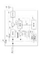
図1は、本発明による送信機のブロック図の一例である。送信機100は、アンテナANT、取得部120、算出部130、送信部140、及びピーク抑圧部150を備える。取得部120は、変調方式検出部122を備える。また、ピーク抑圧部150は、遅延部152、振幅制限部153、フィルタ適用部156、及び減算部157を備え、振幅制限部153は、リミッタ154及び減算部155を備える。送信機100は、ベースバンド信号を処理してOFDMA信号を生成する外部装置(図示せず)から、サブキャリアによって異なる変調方式が割り当てられたサブキャリアで構成される送信すべき信号を受信する。ピーク抑圧部150は、送信すべき信号のピーク電圧を抑圧(低減)する処理を行う(詳細は後述する。)。取得部120は、送信すべき信号の各サブキャリアに割り当てられている変調方式に関する情報を取得する。算出部130は、取得部120で検出した情報に基づき、送信すべき信号に適用する帯域通過フィルタの形状(周波数特性)を求め、当該フィルタのインパルス応答を算出する。算出部130で算出したインパルス応答に基づき、ピーク抑圧部150に含まれるフィルタ適用部156において、送信すべき信号のフィルタリングが行われる。
FIG. 1 is an example of a block diagram of a transmitter according to the present invention. The
ピーク抑圧部150における処理について説明する。ピーク抑圧部150は、振幅制御部153、フィルタ適用部156、及び減算部157を具え、振幅制限部153は、リミッタ154及び減算部155を具える。まず、リミッタ154は、送信すべき信号における振幅値が所定の閾値を超えないように制限する。所定の閾値は、送信機100が、受信機(図示せず)から送信機100に送信された信号をもとに推定した伝送路特性に基づき適宜設定することができる。減算部155は、元の送信すべき信号から、リミッタ154によって振幅値を制限された信号を差し引く処理を行う。従って、振幅制限部153によって取り出される信号(差分データ)は、送信すべき信号のうち振幅値が所定の閾値を超過した部分の信号となる。
Processing in the
振幅制限部153によって取り出された信号(差分データ)を、元の送信から差し引くことによって、送信すべき信号のピーク電力を抑圧することができるが、上述のように、ピーク電力の抑圧によりEVM等が悪化してしまうという問題がある。従って、フィルタ適用部156によって、悪化が及ぶ範囲を所定のサブキャリアのみに制限するためのフィルタリングを行う。このために、本発明による送信機100は、算出部130において、送信すべき信号を構成するサブキャリアのうち相対的に劣化が許容される変調方式、即ち劣化に対する耐性の高い変調方式を割り当てられたサブキャリアを通過させるような帯域通過フィルタのインパルス応答を求める。そして、フィルタ適用部156において、振幅制限部153によって取り出された信号に畳み込むことで、ピーク抑圧信号を相対的に劣化が許容される変調方式が割り当てられたサブキャリアに制限する。相対的に劣化が許容される変調方式は、例えば送信信号のタイムスロットにQPSK,16QAM及び64QAMの変調方式が割り当てられたサブキャリアが混在する場合は、相対的に伝送速度の低いQPSKとなる。減算部157は、遅延部152によって上述のフィルタリング処理に要する時間分遅延された元の送信すべき信号と、フィルタ適用部156によってフィルタリングされた信号との差分信号を生成する。従って、減算部157によって生成された差分信号は、ピーク電力の低減への耐性が高い変調方式が割り当てられたサブキャリアに対して、ピーク電力が低減された信号となる。送信部140は、ピーク抑圧部150から出力された信号を送信する。
By subtracting the signal (difference data) extracted by the
なお、取得部120が、送信すべき信号の各サブキャリアに割り当てられている変調方式に関する情報を取得する手法としては多数考えられるが、例えば、変調方式検出部122によって、外部装置から送信されるベースバンド信号に含まれる制御情報(フレーム制御ヘッダ等)を読み取るか、送信すべき信号をFFT(高速フーリエ変換)し、含まれている基準信号(パイロット信号)から変調方式の推定を行う。
There are many possible methods for the
次に、算出部130がインパルス応答を算出する、送信すべき信号に適用する帯域通過フィルタによるフィルタリング処理について、図を用いて説明する。図2は、本発明によるフィルタリング処理を説明する概略図である。図2は、OFDMAのようなマルチキャリア伝送方式による送信フレームの一例を示す。マルチキャリア伝送方式においては、周波数軸及び時間軸方向のリソースを区切って複数のユーザに割当てることができ、ユーザの伝送するデータに応じて適応的に変調方式を割り当てることが可能なため、図2のように、フレーム内に複数の変調方式が混在した形となる。ここで、図におけるスロットは、時間軸方向におけるリソースを割り当てる単位を意味する。例えばN番目のスロットにおいては、QPSK、16QAM、64QAMの変調信号が存在し、周波数軸方向の中心付近に、最も多値数の小さい(伝送速度の低い)QPSK変調信号が存在している。
Next, the filtering process by the band pass filter applied to the signal to be transmitted, in which the
取得部120は、上述した手法を用いて、各サブキャリアに割り当てられた変調方式(図2)に関する情報を取得する。この情報の取得は、タイムスロット毎に行う。例えばN番目のスロットにおいてはピーク電力の低減処理に起因するEVMの劣化に対する許容レベルが高いのは、QPSKが割り当てられたサブキャリアである。すなわち、ピーク電力を低減する信号を、そのサブキャリア領域に制限すれば、送信すべき信号全体の通信品質に及ぼす影響を最小限にすることができる。従って、ピーク低減処理に使用するフィルタの周波数応答は、図2のFT1に示す形状とすればよい。フィルタ適用部156において、振幅制限部153を通過した信号とフィルタFT1のインパルス応答との畳み込み演算が行われ、減算部157によって元の送信すべき信号から差し引かれる余分な信号(所定の閾値を超過した信号)は、ピーク電力の抑制による影響に対する耐性の高い変調方式が割り当てられたサブキャリアで送信される信号となる。ここで、図2のように、各サブキャリアに対する変調方式の割当はスロット毎に変わることも考えられるため、スロットN+1及びスロットN+2に対しては、適用すべきフィルタの形状がそれぞれFT2,FT3のように異なる。従って、それぞれのフィルタのインパルス応答をスロットごとに適応的に算出することによって、常にEVMの劣化による悪影響を最小限に留めることが可能となる。
The
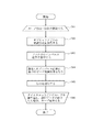
上述のピーク低減処理を、フローチャートを用いて説明する。図4は、本発明の送信機によるピーク低減処理のフローチャートの一例である。送信機100は、タイムスロットごとに、ループ(ステップS12〜S15)を繰り返す。まず、サブキャリアに割り当てられた変調方式に関する情報を取得する(ステップS12)。その後、取得した情報に基づき、タイムスロットのサブキャリアのうち相対的に伝送速度の低い変調方式を割り当てられたサブキャリアの信号を通過させるフィルタのインパルス応答を算出する(ステップS13)。次に、算出したインパルス応答に基づき、上述したピーク低減処理を行い(ステップS14)、ピーク電力を低減した信号を送信する(ステップS15)。そして、送信すべきデータが終了するまで、各タイムスロットでループを繰り返す(ステップS16)。
The peak reduction process described above will be described using a flowchart. FIG. 4 is an example of a flowchart of peak reduction processing by the transmitter of the present invention. The
なお、上述の実施例では、ベースバンド信号の処理を行う外部装置から、既に送信するデータを変調しサブキャリアに割り当てた信号(IQデータを各サブキャリアへマッピングした信号)を受信した態様について説明した。しかしながら、本発明による送信機は、サブキャリアへの割り当て前(マッピング前)のデータを受信し、自装置において、所定の変調方式を所定のサブキャリア領域に割り当てた信号を生成してもよい。更に、その変調方式の割り当て結果を、取得部120に通知するような構成にすることができる。図3に、この場合の本発明の送信機の概略ブロック図を示す。送信機100Aにおいて、図2の送信機100と同様の機能を有する構成部には、同様の符号を付す。図3に示す送信機100Aは、図1に示す送信機100において、送信データ生成部110をさらに具える。送信データ生成部110は、データ割当部112及びIFFT(逆フーリエ変換)部114を具える。データ割当部112は、パケット毎に異なる変調方式で変調されたIQデータを外部装置から受信し、これらのデータを、サブキャリア上にマッピングする。その際、各スロットにおいて、相対的に伝送速度の低い変調方式を所定のサブキャリアにまとめて割り当て、その割当情報を取得部120へ送信する。その後、算出部130は、取得部120から送信された割当て情報に基づいてフィルタのインパルス応答を算出し、ピーク抑圧部150は、ピーク低減処理を行う。その他の機能部及びピーク低減処理は、上述の実施例と同様であるため説明を省略する。なお、取得部120を設けず、送信データ生成部110から直接算出部130へ割当て情報を送信してもよい。本実施例では変調方式の検出を行わないため、EVMの劣化による悪影響を最小限に留めるという利点とともに、処理負荷が軽減されるという利点がある。
In the above-described embodiment, a mode is described in which a signal (modulated IQ data is mapped to each subcarrier) received by modulating an already transmitted data and assigning it to a subcarrier from an external device that performs baseband signal processing is described. did. However, the transmitter according to the present invention may receive data before allocation to subcarriers (before mapping) and generate a signal in which a predetermined modulation scheme is allocated to a predetermined subcarrier region in its own device. Furthermore, it is possible to adopt a configuration that notifies the
本発明による同期制御方法の利点を再度述べる。本発明によれば、OFDMA等のマルチチャネル伝送方式においてQPSKや64QAMといった複数の変調方式が同一タイムスロットに混在する場合に、ピーク抑圧によるEVMの劣化が及ぶ範囲を、大きな劣化が許容されるサブキャリアのみに制限することが可能となる。また、タイムスロット毎に取得したサブキャリアへの変調方式の割当て情報をに基づいて適応的にフィルタを生成するため、全通信にわたって高品質な通信を行うことができる。さらに、送信する信号の変調方式の割当て情報を自装置にて検出するため、ベースバンド信号を処理する外部装置に対する制約がないという利点がある。加えて、振幅(ピーク電力)の抑圧を多値数の小さい変調方式に対して行うため、振幅の情報をデータの判別に用いる多値数の大きい変調方式と比べ、受信側での復調の誤りは少なくなる。 The advantages of the synchronous control method according to the present invention will be described again. According to the present invention, when a plurality of modulation schemes such as QPSK and 64QAM are mixed in the same time slot in a multi-channel transmission scheme such as OFDMA, a sub-range in which large degradation is allowed within a range where degradation of EVM due to peak suppression extends. It is possible to limit only to carriers. In addition, since the filter is adaptively generated based on the allocation information of the modulation scheme to the subcarrier acquired for each time slot, high-quality communication can be performed over all communication. Further, since the allocation information of the modulation scheme of the signal to be transmitted is detected by the own apparatus, there is an advantage that there is no restriction on the external apparatus that processes the baseband signal. In addition, since the amplitude (peak power) is suppressed for a modulation system with a small multi-level number, demodulation errors on the receiving side are compared with those for a modulation system with a large multi-level number that uses amplitude information for data discrimination. Will be less.
本発明を諸図面や実施例に基づき説明してきたが、当業者であれば本開示に基づき種々の変形や修正を行うことが容易であることに注意されたい。従って、これらの変形や修正は本発明の範囲に含まれることに留意されたい。例えば、各手段、各ステップなどに含まれる機能などは論理的に矛盾しないように再配置可能であり、複数の手段やステップなどを1つに組み合わせたり、あるいは分割したりすることが可能である。 Although the present invention has been described based on the drawings and examples, it should be noted that those skilled in the art can easily make various modifications and corrections based on the present disclosure. Therefore, it should be noted that these variations and modifications are included in the scope of the present invention. For example, the functions included in each means, each step, etc. can be rearranged so as not to be logically contradictory, and a plurality of means, steps, etc. can be combined into one or divided. .
100,100A 送信機
110 送信データ生成部
112 データ割当部
114 IFFT
120 取得部
122 変調方式検出部
130 算出部
140 送信部
150 ピーク抑圧部
152 遅延部
153 振幅制限部
154 リミッタ
155,157 減算部
156 フィルタ適用部
ANT アンテナ
FT1〜FT3 フィルタ特性
100,
DESCRIPTION OF
Claims (5)
送信すべき信号を構成するサブキャリアに割り当てられた変調方式に関する情報を取得する取得部と、
前記取得部で取得された情報に基づき、前記送信すべき信号を構成するサブキャリアのうち相対的に伝送速度の低い変調方式を割り当てられたサブキャリアで送信する信号のピーク電力の低減処理を行うピーク低減処理部と、
を備えることを特徴とする送信機。 A transmitter for adaptively allocating modulation schemes to the plurality of subcarriers and transmitting signals in an orthogonal frequency division multiple access scheme using a plurality of subcarriers;
An acquisition unit for acquiring information on a modulation scheme allocated to subcarriers constituting a signal to be transmitted;
Based on the information acquired by the acquisition unit, processing for reducing peak power of a signal transmitted on a subcarrier to which a modulation scheme having a relatively low transmission rate is assigned among subcarriers constituting the signal to be transmitted is performed. A peak reduction processing unit;
A transmitter comprising:
前記ピーク低減処理部は、前記送信すべき信号を構成するサブキャリアのうち最も伝送速度の低い変調方式を割り当てられたサブキャリアで送信する信号のピーク電力の低減処理を行う、
ことを特徴とする送信機。 The transmitter of claim 1, wherein
The peak reduction processing unit performs processing for reducing peak power of a signal to be transmitted on a subcarrier assigned a modulation scheme having the lowest transmission rate among subcarriers constituting the signal to be transmitted.
A transmitter characterized by that.
前記取得部は、
前記送信すべき信号に含まれる報知情報から当該送信すべき信号を構成するサブキャリアに割り当てられた変調方式を検出する、
ことを特徴とする送信機。 The transmitter according to claim 1 or 2,
The acquisition unit
Detecting a modulation scheme assigned to subcarriers constituting the signal to be transmitted from broadcast information included in the signal to be transmitted;
A transmitter characterized by that.
隣接する複数のサブキャリアに同一の変調方式を割り当てて前記送信すべき信号を生成する送信データ生成部をさらに含み、
前記取得部は、前記送信データ生成部から、前記サブキャリアに割り当てられた変調方式に関する情報を取得する、
ことを特徴とする送信機。 The transmitter according to claims 1-3.
A transmission data generation unit that generates the signal to be transmitted by allocating the same modulation scheme to a plurality of adjacent subcarriers;
The acquisition unit acquires information on a modulation scheme assigned to the subcarrier from the transmission data generation unit.
A transmitter characterized by that.
送信すべき信号を構成するサブキャリアに割り当てられた変調方式に関する情報を取得するステップと、
前記取得するステップで取得された情報に基づき、前記送信すべき信号を構成するサブキャリアのうち相対的に伝送速度の低い変調方式を割り当てられたサブキャリアで送信するピーク電力の低減処理を行うピーク低減処理ステップと、
を含むことを特徴とする送信制御方法。 A transmission control method for adaptively allocating modulation schemes to the plurality of subcarriers and transmitting signals in an orthogonal frequency division multiple access scheme using a plurality of subcarriers,
Obtaining information on modulation schemes assigned to subcarriers constituting a signal to be transmitted;
Based on the information acquired in the step of acquiring, a peak for performing reduction processing of peak power transmitted on a subcarrier to which a modulation scheme having a relatively low transmission rate is allocated among subcarriers constituting the signal to be transmitted Reduction processing steps;
Including a transmission control method.
Priority Applications (1)
| Application Number | Priority Date | Filing Date | Title |
|---|---|---|---|
| JP2008174359A JP5171439B2 (en) | 2008-07-03 | 2008-07-03 | Transmitter and transmission control method |
Applications Claiming Priority (1)
| Application Number | Priority Date | Filing Date | Title |
|---|---|---|---|
| JP2008174359A JP5171439B2 (en) | 2008-07-03 | 2008-07-03 | Transmitter and transmission control method |
Publications (2)
| Publication Number | Publication Date |
|---|---|
| JP2010016596A true JP2010016596A (en) | 2010-01-21 |
| JP5171439B2 JP5171439B2 (en) | 2013-03-27 |
Family
ID=41702287
Family Applications (1)
| Application Number | Title | Priority Date | Filing Date |
|---|---|---|---|
| JP2008174359A Expired - Fee Related JP5171439B2 (en) | 2008-07-03 | 2008-07-03 | Transmitter and transmission control method |
Country Status (1)
| Country | Link |
|---|---|
| JP (1) | JP5171439B2 (en) |
Cited By (1)
| Publication number | Priority date | Publication date | Assignee | Title |
|---|---|---|---|---|
| JP2020521399A (en) * | 2017-05-24 | 2020-07-16 | テレフオンアクチーボラゲット エルエム エリクソン(パブル) | Scheduling of wireless communication devices |
Citations (2)
| Publication number | Priority date | Publication date | Assignee | Title |
|---|---|---|---|---|
| JP2004104162A (en) * | 2002-09-04 | 2004-04-02 | Hitachi Kokusai Electric Inc | Amplitude limit apparatus |
| JP2005101975A (en) * | 2003-09-25 | 2005-04-14 | Matsushita Electric Ind Co Ltd | Radio communication apparatus and peak suppressing method |
-
2008
- 2008-07-03 JP JP2008174359A patent/JP5171439B2/en not_active Expired - Fee Related
Patent Citations (2)
| Publication number | Priority date | Publication date | Assignee | Title |
|---|---|---|---|---|
| JP2004104162A (en) * | 2002-09-04 | 2004-04-02 | Hitachi Kokusai Electric Inc | Amplitude limit apparatus |
| JP2005101975A (en) * | 2003-09-25 | 2005-04-14 | Matsushita Electric Ind Co Ltd | Radio communication apparatus and peak suppressing method |
Cited By (3)
| Publication number | Priority date | Publication date | Assignee | Title |
|---|---|---|---|---|
| JP2020521399A (en) * | 2017-05-24 | 2020-07-16 | テレフオンアクチーボラゲット エルエム エリクソン(パブル) | Scheduling of wireless communication devices |
| JP6999702B2 (en) | 2017-05-24 | 2022-01-19 | テレフオンアクチーボラゲット エルエム エリクソン(パブル) | Wireless communication device scheduling |
| US11523406B2 (en) | 2017-05-24 | 2022-12-06 | Telefonaktiebolaget Lm Ericsson (Publ) | Scheduling of wireless communication devices |
Also Published As
| Publication number | Publication date |
|---|---|
| JP5171439B2 (en) | 2013-03-27 |
Similar Documents
| Publication | Publication Date | Title |
|---|---|---|
| JP4575318B2 (en) | Base station, radio terminal and radio communication method | |
| US8705441B2 (en) | Joint use of multi-carrier and single-carrier multiplexing schemes for wireless communication | |
| KR100849749B1 (en) | Transmitter and transmission method | |
| US7983357B2 (en) | Method for transmitting and receiving data in a multi-carrier system | |
| US20090092195A1 (en) | Method and system for adaptive peak to average power ratio reduction in orthogonal frequency division multiplexing communication networks | |
| US9374204B2 (en) | Transmission method and apparatus for cancelling inter-carrier interference | |
| US20100067615A1 (en) | Method for Optimizing Signals with Multiple Subcarriers | |
| JP2004523945A (en) | Error reduction method and apparatus in quadrature modulation system | |
| WO2009089753A1 (en) | A method and device for peak-to-average ratio suppression in multi-carrier orthogonal frequency division multiplexing system | |
| JP5061892B2 (en) | Signal multiplexing method, transmitting station and receiving station in radio communication system | |
| KR20060131094A (en) | Method of transmitting pilot signal for dft spread orthogonal frequency division multiple access system | |
| WO2008106857A1 (en) | Method, device for reducing signal peak value and transmitting device | |
| WO2011105275A1 (en) | Wireless communication system, radio transmitting apparatus and radio transmitting method | |
| JP2006287344A (en) | Multicarrier wireless communication apparatus and subcarrier assigning method thereof | |
| US8588153B2 (en) | Method and apparatus for transmitting uplink control channel in a mobile communication system | |
| CA3039968A1 (en) | Method for determining reserved tones and transmitter for performing papr reduction using tone reservation | |
| WO2019176931A1 (en) | Communication system using wired transmission line and multi-carrier modulation | |
| JP5646494B2 (en) | Telecommunications method and system | |
| US10361897B2 (en) | Peak-to-average power ratio reduction in a multi-carrier signal | |
| WO2017114038A1 (en) | Signal processing method and apparatus, transmission node and storage medium | |
| JP5171439B2 (en) | Transmitter and transmission control method | |
| JP2010206385A (en) | Transmitter, receiver, power amplification method, and signal demodulation method | |
| US20130070811A1 (en) | Transmission/reception apparatus and method for filtered multi-tone system | |
| US8477882B2 (en) | Radio apparatus | |
| AU2019203584C1 (en) | Method for determining reserved tones and transmitter for performing papr reduction using tone reservation |
Legal Events
| Date | Code | Title | Description |
|---|---|---|---|
| A621 | Written request for application examination |
Free format text: JAPANESE INTERMEDIATE CODE: A621 Effective date: 20110628 |
|
| A977 | Report on retrieval |
Free format text: JAPANESE INTERMEDIATE CODE: A971007 Effective date: 20120913 |
|
| A131 | Notification of reasons for refusal |
Free format text: JAPANESE INTERMEDIATE CODE: A131 Effective date: 20120918 |
|
| A521 | Written amendment |
Free format text: JAPANESE INTERMEDIATE CODE: A523 Effective date: 20121116 |
|
| TRDD | Decision of grant or rejection written | ||
| A01 | Written decision to grant a patent or to grant a registration (utility model) |
Free format text: JAPANESE INTERMEDIATE CODE: A01 Effective date: 20121218 |
|
| A61 | First payment of annual fees (during grant procedure) |
Free format text: JAPANESE INTERMEDIATE CODE: A61 Effective date: 20121225 |
|
| R150 | Certificate of patent or registration of utility model |
Ref document number: 5171439 Country of ref document: JP Free format text: JAPANESE INTERMEDIATE CODE: R150 |
|
| LAPS | Cancellation because of no payment of annual fees | ||
| S111 | Request for change of ownership or part of ownership |
Free format text: JAPANESE INTERMEDIATE CODE: R313111 |
|
| R360 | Written notification for declining of transfer of rights |
Free format text: JAPANESE INTERMEDIATE CODE: R360 |
|
| R360 | Written notification for declining of transfer of rights |
Free format text: JAPANESE INTERMEDIATE CODE: R360 |
|
| R371 | Transfer withdrawn |
Free format text: JAPANESE INTERMEDIATE CODE: R371 |