JP2010015985A - Mechanical fastener for coupling with electric terminal and method for coupling with electric terminal in battery module - Google Patents
Mechanical fastener for coupling with electric terminal and method for coupling with electric terminal in battery module Download PDFInfo
- Publication number
- JP2010015985A JP2010015985A JP2009153748A JP2009153748A JP2010015985A JP 2010015985 A JP2010015985 A JP 2010015985A JP 2009153748 A JP2009153748 A JP 2009153748A JP 2009153748 A JP2009153748 A JP 2009153748A JP 2010015985 A JP2010015985 A JP 2010015985A
- Authority
- JP
- Japan
- Prior art keywords
- plate
- cover
- trapezoidal plate
- hole
- mechanical fastener
- Prior art date
- Legal status (The legal status is an assumption and is not a legal conclusion. Google has not performed a legal analysis and makes no representation as to the accuracy of the status listed.)
- Granted
Links
- 230000008878 coupling Effects 0.000 title claims abstract description 33
- 238000010168 coupling process Methods 0.000 title claims abstract description 33
- 238000005859 coupling reaction Methods 0.000 title claims abstract description 33
- 238000000034 method Methods 0.000 title claims abstract description 10
- 230000000712 assembly Effects 0.000 description 5
- 238000000429 assembly Methods 0.000 description 5
- RYGMFSIKBFXOCR-UHFFFAOYSA-N Copper Chemical compound [Cu] RYGMFSIKBFXOCR-UHFFFAOYSA-N 0.000 description 4
- 229910052802 copper Inorganic materials 0.000 description 4
- 239000010949 copper Substances 0.000 description 4
- PXHVJJICTQNCMI-UHFFFAOYSA-N Nickel Chemical compound [Ni] PXHVJJICTQNCMI-UHFFFAOYSA-N 0.000 description 2
- 229910000831 Steel Inorganic materials 0.000 description 2
- 238000001514 detection method Methods 0.000 description 2
- 239000000463 material Substances 0.000 description 2
- 238000012986 modification Methods 0.000 description 2
- 230000004048 modification Effects 0.000 description 2
- 239000010959 steel Substances 0.000 description 2
- 239000004020 conductor Substances 0.000 description 1
- 238000010586 diagram Methods 0.000 description 1
- 230000000694 effects Effects 0.000 description 1
- -1 for example Substances 0.000 description 1
- 238000004519 manufacturing process Methods 0.000 description 1
- 229910052759 nickel Inorganic materials 0.000 description 1
- 238000007747 plating Methods 0.000 description 1
- 238000003825 pressing Methods 0.000 description 1
Images


Classifications
-
- H—ELECTRICITY
- H01—ELECTRIC ELEMENTS
- H01M—PROCESSES OR MEANS, e.g. BATTERIES, FOR THE DIRECT CONVERSION OF CHEMICAL ENERGY INTO ELECTRICAL ENERGY
- H01M50/00—Constructional details or processes of manufacture of the non-active parts of electrochemical cells other than fuel cells, e.g. hybrid cells
- H01M50/50—Current conducting connections for cells or batteries
- H01M50/502—Interconnectors for connecting terminals of adjacent batteries; Interconnectors for connecting cells outside a battery casing
- H01M50/514—Methods for interconnecting adjacent batteries or cells
- H01M50/517—Methods for interconnecting adjacent batteries or cells by fixing means, e.g. screws, rivets or bolts
-
- H—ELECTRICITY
- H01—ELECTRIC ELEMENTS
- H01M—PROCESSES OR MEANS, e.g. BATTERIES, FOR THE DIRECT CONVERSION OF CHEMICAL ENERGY INTO ELECTRICAL ENERGY
- H01M6/00—Primary cells; Manufacture thereof
- H01M6/42—Grouping of primary cells into batteries
Abstract
Description
本願は、概して、バッテリモジュールにおける電気端子に結合するための機械的ファスナー及び電気端子に結合するための方法に関する。 The present application relates generally to mechanical fasteners for coupling to electrical terminals in battery modules and methods for coupling to electrical terminals.
バッテリパックは、一般に、複数のバッテリセルを備えてなる。各バッテリセルは、ファスナーを介して他のバッテリセルの端子に結合される端子を更に備えてなる。しかしながら、ファスナーを製造工程中に取り付けることは、比較的困難である。 A battery pack generally includes a plurality of battery cells. Each battery cell further includes a terminal coupled to a terminal of another battery cell via a fastener. However, attaching fasteners during the manufacturing process is relatively difficult.
従って、本件発明者等は、上記欠点を最小限にする及び/又は解消する、改良された機械的ファスナーに対する必要性を認識していた。 Accordingly, the inventors have recognized the need for an improved mechanical fastener that minimizes and / or eliminates the above disadvantages.
例示的な実施形態によるバッテリモジュールにおける電気端子に結合するための機械的ファスナーが提供される。本発明のバッテリモジュールは、上面、底面、並びに第一側面及び第二側面を有する台形形状のプレートを備えてなる。第一側面及び第二側面が前記上面と前記底面との間に延出してなる。前記台形形状のプレートが前記上面から前記台形形状のプレート内に延出する第一孔部を有してなる。第一孔部が第一螺合領域を画成してなる。本発明のバッテリモジュールは、第一プレート並びに第一脚部及び第二脚部を有してなるカバー部を更に備えてなる。第一脚部及び第二脚部が第一プレートの両端部に設置され、かつ、第一プレートと一体化されてなる。第一脚部及び第二脚部が第一プレートから外側に延出してなる。第一プレートが第一プレートを通じて延出する第二孔部を有してなる。第一プレートの底面が前記台形形状のプレートの前記上面に支持されてなる。本発明のバッテリモジュールは、第一結合部材を更に備えてなり、第一結合部材が、第一孔部及び第二孔部を通じて延出し、かつ、第一螺合領域に係合し、前記カバー部を前記台形形状のプレートに向けて押圧して、前記台形形状のプレートにおける第一側面及び第二側面の各々に隣接して配置された第一電気端子及び第二電気端子が、第一側面及び第二側面の各々と、前記カバー部の第一脚部及び第二脚部の各々との間に固定されてなる。 A mechanical fastener is provided for coupling to electrical terminals in a battery module according to an exemplary embodiment. The battery module of the present invention includes a trapezoidal plate having a top surface, a bottom surface, and a first side surface and a second side surface. A first side surface and a second side surface extend between the upper surface and the bottom surface. The trapezoidal plate has a first hole extending from the upper surface into the trapezoidal plate. The first hole portion defines a first screwing region. The battery module of the present invention further includes a first plate and a cover portion having a first leg portion and a second leg portion. A 1st leg part and a 2nd leg part are installed in the both ends of a 1st plate, and are integrated with a 1st plate. A first leg and a second leg extend outward from the first plate. The first plate has a second hole extending through the first plate. The bottom surface of the first plate is supported on the top surface of the trapezoidal plate. The battery module of the present invention further includes a first coupling member, the first coupling member extends through the first hole and the second hole, and engages with the first screw region, and the cover A first electric terminal and a second electric terminal disposed adjacent to each of the first side surface and the second side surface of the trapezoidal plate by pressing the portion toward the trapezoidal plate; And it fixes between each of a 2nd side surface, and each of the 1st leg part of the said cover part, and a 2nd leg part.
他の例示的な実施形態による、機械的ファスナーを用いたバッテリモジュールにおける電気端子に結合するための方法が提供される。前記機械的ファスナーが台形形状のプレートとカバー部を有してなる。前記台形形状のプレートが第一孔部を有してなり、前記カバー部が第二孔部を有してなる。本発明の方法は、前記台形形状のプレートを第一電気端子及び第二電気端子に隣接して配置し、第一電気端子及び第二電気端子を、前記台形形状のプレートの両傾斜面(対向する傾斜面)に配置することを含んでなる。本発明の方法は、前記カバー部を前記台形形状のプレートの一部を覆うように配置し、第一電気端子及び第二電気端子を、前記カバー部と前記台形形状のプレートの前記両傾斜面(対向する傾斜面)との間に配置することを更に含んでなる。本発明の方法は、第一孔部及び第二孔部を通じて結合部材を配置し、前記台形形状のプレートを前記カバー部に向けて移動させ、第一電気端子及び第二電気端子を前記台形形状のプレートと前記カバー部との間にそれぞれ固定することを更に含んでなる。 In accordance with another exemplary embodiment, a method for coupling to electrical terminals in a battery module using a mechanical fastener is provided. The mechanical fastener has a trapezoidal plate and a cover portion. The trapezoidal plate has a first hole, and the cover has a second hole. According to the method of the present invention, the trapezoidal plate is disposed adjacent to the first electrical terminal and the second electrical terminal, and the first electrical terminal and the second electrical terminal are disposed on both inclined surfaces (opposite surfaces) of the trapezoidal plate. To be disposed on an inclined surface). In the method of the present invention, the cover part is arranged so as to cover a part of the trapezoidal plate, and the first electric terminal and the second electric terminal are arranged on the both inclined surfaces of the cover part and the trapezoidal plate. It further includes disposing between (facing inclined surfaces). According to the method of the present invention, the coupling member is disposed through the first hole and the second hole, the trapezoidal plate is moved toward the cover, and the first electric terminal and the second electric terminal are moved to the trapezoidal shape. And fixing between the plate and the cover part.
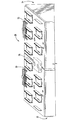
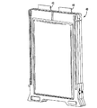
図1及び2において、例示的な実施形態による、電力を提供するためのバッテリアセンブリ20が示されている。バッテリアセンブリ20は、バッテリモジュール22と、連結アセンブリ23と、バッテリモジュール24と、連結アセンブリ25と、及び機械的ファスナー26を備えてなる。機械的ファスナー26の利点は、ファスナー26が、バッテリモジュール22からの電気端子とバッテリモジュール24における電気端子の両方に物理的に結合し、これによりこれらの電気端子を互いに電気的に結合できることである。理解を期すために、バッテリセルアセンブリは、少なくともハウジングと、その内部に収容されたバッテリセルを備えてなる。バッテリモジュールは、その内部に所望の構成で互いに電気的に結合された複数のバッテリセルアセンブリを備えてなる。
1 and 2, a
図2及び3において、バッテリモジュール22が、電流及び電圧を発生するように構成されている。バッテリモジュール22は、互いに電気的に結合された複数のバッテリセルアセンブリを備えてなる。例えば、バッテリモジュール22は、バッテリセルアセンブリ30を備えてなる。このバッテリセルアセンブリ30は、バッテリモジュール22の内部に収容された複数のバッテリセルアセンブリのうちの一つの例示である。バッテリセルアセンブリ30は、電気端子32、34を備えてなる。
2 and 3, the
連結アセンブリ23は、バッテリモジュール22の電気端子を互いに結合するように構成されている。連結アセンブリ23は、バッテリモジュール22の上面に設置されている。
The
図2及び図4において、バッテリモジュール24が、電流及び電圧を発生するように構成されている。バッテリモジュール24は、互いに電気的に結合された複数のバッテリセルアセンブリを備えてなる。例えば、バッテリモジュール24は、バッテリアセンブリ40を備えてなる。このバッテリアセンブリ40は、バッテリモジュール24の内部に収容された複数のバッテリセルアセンブリのうちの一つの例示である。バッテリセルアセンブリ24は、電気端子42、44を備えてなる。
2 and 4, the
連結アセンブリ25は、バッテリモジュール24の電気端子を互いに結合するように構成されている。連結アセンブリ25は、バッテリモジュール24の上面に設置されている。
The
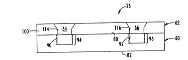
図5、7、及び8において、機械的ファスナー26は、バッテリモジュール22からの一つ又はそれ以上の電気端子、及びバッテリモジュール24からの一つ又はそれ以上の電気端子に結合するように設けられている。特に、機械的ファスナー26は、バッテリモジュール22のバッテリセルアセンブリ30の電気端子34、及びバッテリモジュール24のバッテリセルアセンブリ40の電気端子44に結合するように構成されている。従って、電気端子34及び44は、互いに電気的に結合される。機械的ファスナー26は、台形形状のプレート60と、カバー部62と、及び結合部材64、66を備えてなる。
In FIGS. 5, 7, and 8,
台形形状のプレート60は、上面80と、底面82と、側面84、86と、前面87と、及び後面を備えてなる。上面80は、底面82に実質的に平行であり、底面82から離間して設けられている。前面87は、後面に実質的に平行であり、後面から離間して設けられている。側面84、86は、上面80と底面82の間に延出している。台形形状のプレート60は、上面80からプレート60内に延出する孔部90、92を更に備えてなる。孔部90、92は、プレート60の内部で螺合領域94、96を画成している。プレート60は、前面87からプレート60内に延出する孔部97、98を更に備えてなる。一つの例示的な実施形態において、プレート60はスチールから構成されている。もちろん、プレート60は、他の導電性材料、例えば銅やニッケルメッキした銅から構成することも可能である。図示のように、プレート60は、連結アセンブリ23と連結アセンブリ25の両方の上部に設置されている。
The
図5、6、7、及び8において、カバー部62は、台形形状のプレート60上に支持されるように構成されている。一つの例示的な実施形態において、カバー部62は、スチールから構成されている。もちろん、カバー部62は、他の導電性材料、例えば銅やニッケルメッキした銅から構成することも可能である。カバー部62は、プレート100及び脚部102、104を供えてなる。脚部102、104は、プレート100の両端部に設けられ、プレート100と一体的になされている。更に、脚部102、104は、プレート100から外側に延出している。プレート100は、上面110及び底面112を備えてなる。底面112は、上面110に実質的に平行であり、上面110から離間して設けられている。プレート100は、プレート100を通じて延出する孔部114、116を備えてなる。カバー部62がプレート60上に設置されたとき、孔部114、116は、台形形状のプレート60の孔部90、92とそれぞれ整列するように構成されている。脚部102は、鋸状面である傾斜面120を備えてなる。脚部104は、鋸状面である傾斜面122を備えてなる。
5, 6, 7, and 8, the
図5、7、及び8において、結合部材64、66は、カバー部62を台形形状のプレート60に結合するように設けられている。一つの例示的な実施形態において、結合部材64、66はボルトである。しかしながら、当業者に周知の他のタイプの結合部材を利用することも可能である。結合部材64が、カバー部62の孔部114とプレート60の孔部90を通じて設けられるとともに溝領域94に動作可能に係合すると、カバー部62はプレート60に向かって移動し、これにより、プレート60の各側面84、86に隣接して配置された電気端子34、44が、各側面84、86と各脚部102、104との間に、それぞれ固定される。更に、結合部材66が、カバー部62の孔部116とプレート60の孔部92を通じて設けられるとともに溝領域96に動作可能に係合すると、カバー部62はプレート60に向かって移動し、これによりプレート60の各側面84,86に隣接して配置された電気端子34、44が、各側面84、86と各脚部102、104との間に、それぞれ固定される。
In FIGS. 5, 7, and 8, the
図9において、機械的ファスナー26は、台形形状のプレート60に結合された電圧検出ワイヤ140、142を更に備えてもよい。電圧検出ライン140、142は、台形形状のプレート60において、孔部97、98内にそれぞれ延出する螺子を用いて互いに電気的に結合されてもよい。
In FIG. 9, the
図5、7、及び9を参照して、バッテリモジュールからの電気的端子を結合するための方法を説明する。最初に、電気端子34、44が台形形状のプレート60の側面84、86に隣接して配置されるように、プレート60を連結アセンブリ23、25上に配置する。
A method for coupling electrical terminals from a battery module will be described with reference to FIGS. Initially, the
次に、カバー部62を、台形形状のプレート60が覆われるように配置し、これにより、(i)電気端子34が、カバー部62の脚部102とプレート60の側面84との間に配置され、且つ(ii)電気端子44が、カバー部62の脚部104とプレート60の側面84との間に配置される。
Next, the
次に、結合部材64を、カバー部62の孔部114とプレート60の孔部90を通じて螺合領域94に動作可能に係合するように配置して、カバー部62をプレート60に向けて移動させる。これにより、プレート60の各側面84、86に隣接して配置された電気端子34、44が、プレート60の各側面84、86と各脚部102、104との間にそれぞれ固定される。従って、電気端子32と電気端子44は、機械的ファスナー26を用いて互いに電気的に結合される。
Next, the
次に、結合部材66を、カバー部62の孔部116とプレート60の孔部92を通じて螺合領域96に動作可能に係合するように配置して、カバー部62をプレート60に向けて移動させる。これにより、プレート60の各側面84,86に隣接して配置された電気端子34、44が、プレート60の各側面84、86と各脚部102、104との間にそれぞれ固定される。従って、電気端子32と電気端子44は、機械的ファスナー26を用いて互いに電気的に結合される。
Next, the
機械的ファスナー26は、他のファスナーに対して実質的な利点を提供する。特に、機械的ファスナー26は、台形形状のプレートとカバー部を用いて二つのバッテリモジュールにおける電気端子を互いに結合するという技術的効果を提供する。
本発明を例示的な実施形態を参照しつつ説明したが、当業者には本発明の範囲を逸脱せずに種々の変更が可能であり、且つ種々の構成要素を同等物に代えて用いることが可能であることが理解されるであろう。更に、本発明の本質的な範囲を逸脱せずに、特定の状況又は材料を本発明の教示に適合するように、本発明を様々に変形することができる。従って、本発明を実施するために開示された特定の実施形態に本発明を限定する意図はなく、本発明は添付の請求の範囲に該当する全ての実施形態を含むものである。更に、「第一」、「第二」等の用語の使用は、ある構成要素を他の構成要素から区別するために使用されている。また、「一つの」等の用語の使用は、個数を限定するものではなく、対象項目が少なくとも一つ存在するということを意味するものである。 Although the invention has been described with reference to exemplary embodiments, various modifications can be made by those skilled in the art without departing from the scope of the invention, and various components may be substituted for equivalents. It will be understood that this is possible. In addition, various modifications may be made to the invention to adapt a particular situation or material to the teachings of the invention without departing from the essential scope thereof. Accordingly, there is no intention to limit the invention to the specific embodiments disclosed for practicing the invention, and the invention includes all embodiments falling within the scope of the appended claims. Furthermore, the use of terms such as “first”, “second”, etc. is used to distinguish one component from another. The use of a term such as “one” does not limit the number, but means that there is at least one target item.
Claims (5)
台形形状のプレートと、
前記台形形状のプレートが、上面、底面、並びに第一側面及び第二側面を有してなり、第一側面及び第二側面が前記上面と前記底面との間に延出してなり、前記台形形状のプレートが前記上面から前記台形形状のプレート内に延出する第一孔部を有してなり、第一孔部が第一螺合領域を画成してなり、
カバー部と、及び
前記カバー部が第一プレート並びに第一脚部及び第二脚部を有してなり、第一脚部及び第二脚部が第一プレートの両端部に設置され、かつ、第一プレートと一体化されてなり、第一脚部及び第二脚部が第一プレートから外側に延出してなり、第一プレートが第一プレートを通じて延出する第二孔部を有してなり、第一プレートの底面が前記台形形状のプレートの前記上面に支持されてなり、
第一結合部材を備えてなり、
第一結合部材が、第一孔部及び第二孔部を通じて延出し、かつ、第一螺合領域に係合し、前記カバー部を前記台形形状のプレートに向けて押圧して、前記台形形状のプレートにおける第一側面及び第二側面の各々に隣接して配置された第一電気端子及び第二電気端子が、第一側面及び第二側面の各々と、前記カバー部の第一脚部及び第二脚部の各々との間に固定されてなる、機械的ファスナー。 A mechanical fastener for coupling to an electrical terminal in a battery module,
A trapezoidal plate,
The trapezoidal plate has a top surface, a bottom surface, and a first side surface and a second side surface, and the first side surface and the second side surface extend between the top surface and the bottom surface, and the trapezoidal shape The plate has a first hole extending from the upper surface into the trapezoidal plate, the first hole defining a first screwing region,
A cover part, and the cover part has a first plate and a first leg part and a second leg part, the first leg part and the second leg part are installed at both ends of the first plate, and Integrated with the first plate, the first leg and the second leg extend outward from the first plate, the first plate has a second hole extending through the first plate The bottom surface of the first plate is supported on the top surface of the trapezoidal plate,
Comprising a first coupling member,
The first coupling member extends through the first hole portion and the second hole portion, engages with the first screwing region, presses the cover portion toward the trapezoidal plate, and the trapezoidal shape. A first electrical terminal and a second electrical terminal disposed adjacent to each of the first side surface and the second side surface of the plate, each of the first side surface and the second side surface, the first leg portion of the cover portion, and A mechanical fastener fixed between each of the second legs.
前記機械的ファスナーが台形形状のプレートとカバー部を有してなり、前記台形形状のプレートが第一孔部を有してなり、前記カバー部が第二孔部を有してなるものであり、
前記台形形状のプレートを第一電気端子及び第二電気端子に隣接して配置し、第一電気端子及び第二電気端子を、前記台形形状のプレートの両傾斜面に配置し、
前記カバー部を前記台形形状のプレートの一部を覆うように配置し、第一電気端子及び第二電気端子を、前記カバー部と前記台形形状のプレートの前記両傾斜面との間に配置し、及び、
第一孔部及び第二孔部を通じて結合部材を配置し、前記台形形状のプレートを前記カバー部に向けて移動させ、第一電気端子及び第二電気端子を前記台形形状のプレートと前記カバー部との間にそれぞれ固定することを含んでなる、方法。 A method for coupling to an electrical terminal in a battery module using a mechanical fastener,
The mechanical fastener has a trapezoidal plate and a cover part, the trapezoidal plate has a first hole part, and the cover part has a second hole part. ,
The trapezoidal plate is disposed adjacent to the first electrical terminal and the second electrical terminal, the first electrical terminal and the second electrical terminal are disposed on both inclined surfaces of the trapezoidal plate,
The cover part is arranged so as to cover a part of the trapezoidal plate, and the first electric terminal and the second electric terminal are arranged between the cover part and the inclined surfaces of the trapezoidal plate. ,as well as,
A coupling member is disposed through the first hole and the second hole, the trapezoidal plate is moved toward the cover, and the first electric terminal and the second electric terminal are moved to the trapezoidal plate and the cover. Each comprising fixing between and a method.
Applications Claiming Priority (2)
| Application Number | Priority Date | Filing Date | Title |
|---|---|---|---|
| US12/164,843 US7563137B1 (en) | 2008-06-30 | 2008-06-30 | Mechanical fastener for coupling to electrical terminals of battery modules and method for coupling to electrical terminals |
| US12/164,843 | 2008-06-30 |
Publications (2)
| Publication Number | Publication Date |
|---|---|
| JP2010015985A true JP2010015985A (en) | 2010-01-21 |
| JP5108835B2 JP5108835B2 (en) | 2012-12-26 |
Family
ID=40821828
Family Applications (1)
| Application Number | Title | Priority Date | Filing Date |
|---|---|---|---|
| JP2009153748A Active JP5108835B2 (en) | 2008-06-30 | 2009-06-29 | Mechanical fastener for coupling to electrical terminals in a battery module and method for coupling to electrical terminals |
Country Status (6)
| Country | Link |
|---|---|
| US (1) | US7563137B1 (en) |
| EP (1) | EP2141757B1 (en) |
| JP (1) | JP5108835B2 (en) |
| KR (1) | KR100996957B1 (en) |
| CN (1) | CN101621119B (en) |
| AT (1) | ATE528809T1 (en) |
Cited By (4)
| Publication number | Priority date | Publication date | Assignee | Title |
|---|---|---|---|---|
| JP2011165628A (en) * | 2010-02-15 | 2011-08-25 | Toshiba Corp | Secondary battery device |
| JP2011526730A (en) * | 2008-06-30 | 2011-10-13 | エルジー・ケム・リミテッド | Battery module with rubber cooling manifold |
| WO2013132978A1 (en) * | 2012-03-08 | 2013-09-12 | 日産自動車株式会社 | Assembled battery |
| JP2015511384A (en) * | 2012-02-16 | 2015-04-16 | エルジー・ケム・リミテッド | Battery cell interconnection and voltage sensing assembly and method of manufacturing the assembly |
Families Citing this family (17)
| Publication number | Priority date | Publication date | Assignee | Title |
|---|---|---|---|---|
| US8163412B2 (en) * | 2008-06-30 | 2012-04-24 | Lg Chem, Ltd. | Battery cell interconnect and voltage sensing assembly and method for coupling a battery cell assembly thereto |
| US8035986B2 (en) * | 2008-06-30 | 2011-10-11 | Lg Chem, Ltd. | Battery cell interconnect and voltage sensing assembly and method for coupling battery cell assemblies thereto |
| US8098126B2 (en) * | 2009-04-22 | 2012-01-17 | Lg Chem, Ltd. | High voltage service disconnect assembly |
| KR101137365B1 (en) * | 2010-05-20 | 2012-04-20 | 에스비리모티브 주식회사 | Battery pack |
| KR101441423B1 (en) * | 2010-09-01 | 2014-10-20 | 에스케이이노베이션 주식회사 | High-Voltage Battery with Integrated Battery Connector |
| US9178192B2 (en) | 2011-05-13 | 2015-11-03 | Lg Chem, Ltd. | Battery module and method for manufacturing the battery module |
| US9496544B2 (en) | 2011-07-28 | 2016-11-15 | Lg Chem. Ltd. | Battery modules having interconnect members with vibration dampening portions |
| KR101287107B1 (en) | 2011-08-25 | 2013-07-17 | 로베르트 보쉬 게엠베하 | Battery module with connecting member |
| US8974938B2 (en) | 2011-08-30 | 2015-03-10 | Lg Chem, Ltd. | Battery system and method for coupling a battery cell assembly to an electrically non-conductive base member |
| US8871376B2 (en) | 2011-08-31 | 2014-10-28 | Lg Chem, Ltd. | Interconnection assemblies and methods for forming the interconnection assemblies in a battery module |
| JP6023416B2 (en) * | 2011-10-19 | 2016-11-09 | 矢崎総業株式会社 | Power supply |
| US9437859B2 (en) | 2014-04-07 | 2016-09-06 | Lg Chem, Ltd. | Battery cell interconnect and voltage sensing assembly and a battery module |
| US9620761B2 (en) | 2014-09-09 | 2017-04-11 | Lg Chem, Ltd. | Battery cell interconnect and voltage sensing assembly and a battery module |
| US9905892B2 (en) | 2015-02-09 | 2018-02-27 | Lg Chem, Ltd. | Battery module and method of coupling first and second electrical terminals of first and second battery cells to first and second voltage sense members of an interconnect assembly |
| US10020483B2 (en) | 2015-02-09 | 2018-07-10 | Lg Chem, Ltd. | Battery module and method of coupling first and second electrical terminals of first and second battery cells to a voltage sense member of an interconnect assembly |
| US11158890B2 (en) | 2017-08-18 | 2021-10-26 | Hyliion Inc. | Battery pack optimization for thermal management |
| US20230125261A1 (en) * | 2021-10-21 | 2023-04-27 | Hyliion Inc. | System and method for managing battery temperatures in a battery pack |
Citations (6)
| Publication number | Priority date | Publication date | Assignee | Title |
|---|---|---|---|---|
| JP2003323879A (en) * | 2002-05-07 | 2003-11-14 | Fuji Heavy Ind Ltd | Electrode connecting structure of flat battery |
| JP2004006141A (en) * | 2002-05-31 | 2004-01-08 | Fuji Heavy Ind Ltd | Connection structure of battery cell, and method of connection of battery cell |
| WO2006046585A1 (en) * | 2004-10-29 | 2006-05-04 | Nec Corporation | Coupling device, storing case and method for manufacturing electric device assembly |
| JP2007087907A (en) * | 2005-09-26 | 2007-04-05 | Fuji Heavy Ind Ltd | Case structure of power storage unit cell |
| JP2008071733A (en) * | 2006-09-11 | 2008-03-27 | Samsung Sdi Co Ltd | Battery module |
| JP2008516383A (en) * | 2004-10-06 | 2008-05-15 | バッツキャップ | A battery module comprising an energy storage element, wherein the contacts are activated by tightening the layers together |
Family Cites Families (7)
| Publication number | Priority date | Publication date | Assignee | Title |
|---|---|---|---|---|
| CN2077160U (en) * | 1990-09-13 | 1991-05-15 | 顾海涌 | Combined connecting terminal board |
| AU654400B2 (en) * | 1991-12-04 | 1994-11-03 | Gnb Industrial Battery Company | Galvanic cells and batteries having a novel grid, strap and intercell weld arrangement |
| JP3653131B2 (en) * | 1995-12-28 | 2005-05-25 | 日本発条株式会社 | Conductive contact |
| JP3990960B2 (en) * | 2002-08-30 | 2007-10-17 | 矢崎総業株式会社 | Battery connection plate and its mounting structure |
| KR100905391B1 (en) | 2004-12-24 | 2009-06-30 | 주식회사 엘지화학 | Terminal-linking Member of Secondary Battery Module |
| CN2819483Y (en) * | 2005-04-15 | 2006-09-20 | 金达时发展有限公司 | Thin-plated assembled connector of lithium battery |
| KR100684763B1 (en) * | 2005-07-29 | 2007-02-20 | 삼성에스디아이 주식회사 | Secondary battery module and connector |
-
2008
- 2008-06-30 US US12/164,843 patent/US7563137B1/en active Active
- 2008-07-26 KR KR1020080073268A patent/KR100996957B1/en active IP Right Grant
-
2009
- 2009-06-23 AT AT09163522T patent/ATE528809T1/en not_active IP Right Cessation
- 2009-06-23 EP EP09163522A patent/EP2141757B1/en active Active
- 2009-06-29 CN CN2009101506787A patent/CN101621119B/en active Active
- 2009-06-29 JP JP2009153748A patent/JP5108835B2/en active Active
Patent Citations (6)
| Publication number | Priority date | Publication date | Assignee | Title |
|---|---|---|---|---|
| JP2003323879A (en) * | 2002-05-07 | 2003-11-14 | Fuji Heavy Ind Ltd | Electrode connecting structure of flat battery |
| JP2004006141A (en) * | 2002-05-31 | 2004-01-08 | Fuji Heavy Ind Ltd | Connection structure of battery cell, and method of connection of battery cell |
| JP2008516383A (en) * | 2004-10-06 | 2008-05-15 | バッツキャップ | A battery module comprising an energy storage element, wherein the contacts are activated by tightening the layers together |
| WO2006046585A1 (en) * | 2004-10-29 | 2006-05-04 | Nec Corporation | Coupling device, storing case and method for manufacturing electric device assembly |
| JP2007087907A (en) * | 2005-09-26 | 2007-04-05 | Fuji Heavy Ind Ltd | Case structure of power storage unit cell |
| JP2008071733A (en) * | 2006-09-11 | 2008-03-27 | Samsung Sdi Co Ltd | Battery module |
Cited By (4)
| Publication number | Priority date | Publication date | Assignee | Title |
|---|---|---|---|---|
| JP2011526730A (en) * | 2008-06-30 | 2011-10-13 | エルジー・ケム・リミテッド | Battery module with rubber cooling manifold |
| JP2011165628A (en) * | 2010-02-15 | 2011-08-25 | Toshiba Corp | Secondary battery device |
| JP2015511384A (en) * | 2012-02-16 | 2015-04-16 | エルジー・ケム・リミテッド | Battery cell interconnection and voltage sensing assembly and method of manufacturing the assembly |
| WO2013132978A1 (en) * | 2012-03-08 | 2013-09-12 | 日産自動車株式会社 | Assembled battery |
Also Published As
| Publication number | Publication date |
|---|---|
| KR100996957B1 (en) | 2010-11-26 |
| EP2141757A1 (en) | 2010-01-06 |
| CN101621119B (en) | 2012-09-26 |
| JP5108835B2 (en) | 2012-12-26 |
| KR20100003133A (en) | 2010-01-07 |
| EP2141757B1 (en) | 2011-10-12 |
| US7563137B1 (en) | 2009-07-21 |
| CN101621119A (en) | 2010-01-06 |
| ATE528809T1 (en) | 2011-10-15 |
Similar Documents
| Publication | Publication Date | Title |
|---|---|---|
| JP5108835B2 (en) | Mechanical fastener for coupling to electrical terminals in a battery module and method for coupling to electrical terminals | |
| AU2012373356B2 (en) | Non-welded battery module | |
| JP3212318U (en) | Connection member, connection assembly, battery module support assembly, and battery module | |
| KR102247392B1 (en) | Battery module | |
| US20110052961A1 (en) | Battery With a Heat Conducting Plate and Several Individual Cells | |
| US20110027622A1 (en) | Battery pack and method of manufacturing battery pack | |
| EP2706828A2 (en) | Coupling assembly of power semiconductor device and PCB and method for manufacturing the same | |
| KR20120108396A (en) | Battery cell of lamination type | |
| JP2019003729A (en) | Battery pack | |
| CN109390539B (en) | Electrode contact structure of bus bar module | |
| US20130011718A1 (en) | Battery module | |
| CN105895847B (en) | A kind of lug attachment device, power battery module and automobile | |
| JP2014229681A (en) | Power storage unit | |
| TWM462957U (en) | Electrical core fixing device and the power battery pack thereof | |
| CN109065937B (en) | Tray type battery capacity-dividing cabinet | |
| CN205647423U (en) | Junction box of solar photovoltaic module | |
| US20120248594A1 (en) | Junction box and manufacturing method thereof | |
| JP6236438B2 (en) | Fuel cell component with embedded power connector | |
| CN201167110Y (en) | Circuit board connection structure for two-sided charged charger | |
| CN219457865U (en) | Battery module and battery pack | |
| CN213990598U (en) | Photovoltaic junction box and photovoltaic module | |
| KR200467903Y1 (en) | Connection apparatus for battery tab | |
| KR200467875Y1 (en) | Connection apparatus for battery tab | |
| JP3163020U (en) | Battery connection connector | |
| KR200489344Y1 (en) | Apparatus for cell balancing the battery module |
Legal Events
| Date | Code | Title | Description |
|---|---|---|---|
| A977 | Report on retrieval |
Free format text: JAPANESE INTERMEDIATE CODE: A971007 Effective date: 20120518 |
|
| A131 | Notification of reasons for refusal |
Free format text: JAPANESE INTERMEDIATE CODE: A131 Effective date: 20120525 |
|
| A521 | Request for written amendment filed |
Free format text: JAPANESE INTERMEDIATE CODE: A523 Effective date: 20120822 |
|
| TRDD | Decision of grant or rejection written | ||
| A01 | Written decision to grant a patent or to grant a registration (utility model) |
Free format text: JAPANESE INTERMEDIATE CODE: A01 Effective date: 20120907 |
|
| A01 | Written decision to grant a patent or to grant a registration (utility model) |
Free format text: JAPANESE INTERMEDIATE CODE: A01 |
|
| A61 | First payment of annual fees (during grant procedure) |
Free format text: JAPANESE INTERMEDIATE CODE: A61 Effective date: 20121005 |
|
| R150 | Certificate of patent or registration of utility model |
Ref document number: 5108835 Country of ref document: JP Free format text: JAPANESE INTERMEDIATE CODE: R150 Free format text: JAPANESE INTERMEDIATE CODE: R150 |
|
| FPAY | Renewal fee payment (event date is renewal date of database) |
Free format text: PAYMENT UNTIL: 20151012 Year of fee payment: 3 |
|
| S531 | Written request for registration of change of domicile |
Free format text: JAPANESE INTERMEDIATE CODE: R313531 |
|
| R371 | Transfer withdrawn |
Free format text: JAPANESE INTERMEDIATE CODE: R371 |
|
| S531 | Written request for registration of change of domicile |
Free format text: JAPANESE INTERMEDIATE CODE: R313531 |
|
| R350 | Written notification of registration of transfer |
Free format text: JAPANESE INTERMEDIATE CODE: R350 |
|
| RD02 | Notification of acceptance of power of attorney |
Free format text: JAPANESE INTERMEDIATE CODE: R3D02 |
|
| R250 | Receipt of annual fees |
Free format text: JAPANESE INTERMEDIATE CODE: R250 |
|
| R250 | Receipt of annual fees |
Free format text: JAPANESE INTERMEDIATE CODE: R250 |
|
| R250 | Receipt of annual fees |
Free format text: JAPANESE INTERMEDIATE CODE: R250 |
|
| R250 | Receipt of annual fees |
Free format text: JAPANESE INTERMEDIATE CODE: R250 |
|
| R250 | Receipt of annual fees |
Free format text: JAPANESE INTERMEDIATE CODE: R250 |
|
| R250 | Receipt of annual fees |
Free format text: JAPANESE INTERMEDIATE CODE: R250 |
|
| R250 | Receipt of annual fees |
Free format text: JAPANESE INTERMEDIATE CODE: R250 |
|
| S111 | Request for change of ownership or part of ownership |
Free format text: JAPANESE INTERMEDIATE CODE: R313111 |
|
| R350 | Written notification of registration of transfer |
Free format text: JAPANESE INTERMEDIATE CODE: R350 |
|
| R250 | Receipt of annual fees |
Free format text: JAPANESE INTERMEDIATE CODE: R250 |
|
| R250 | Receipt of annual fees |
Free format text: JAPANESE INTERMEDIATE CODE: R250 |