−第1の実施の形態−
本発明は、二次電池を利用した大型車両用電源装置の冷却性能を改善するように構成したことが特徴である。図1〜図9および図13〜図15を参照して、本発明を大型自動車用電源装置に適用した一実施の形態について説明する。
-First embodiment-
The present invention is characterized in that it is configured to improve the cooling performance of a power supply device for a large vehicle using a secondary battery. An embodiment in which the present invention is applied to a power supply device for a large automobile will be described with reference to FIGS.
以下に説明する一実施の形態では、大型車両用電源装置を、大型のハイブリッド自動車用駆動システムの駆動電源に適用した場合を例に挙げて説明する。大型のハイブリッド自動車としては、ハイブリッドバスなどの乗合自動車、ハイブリッドトラックなどの貨物自動車などがある。また、以下に説明する構成は、ハイブリッド電車などの鉄道車両などにも適用できる。
In an embodiment described below, a case where a power supply device for a large vehicle is applied to a drive power source of a drive system for a large hybrid vehicle will be described as an example. Large hybrid vehicles include passenger cars such as hybrid buses and freight vehicles such as hybrid trucks. The configuration described below can also be applied to railway vehicles such as hybrid trains.
<大型のハイブリッド自動車用駆動システムの概略構成>
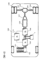
まず、図13を用いて、大型のハイブリッド自動車用駆動システムについて説明する。
図13は、大型のハイブリッド自動車用駆動システムの概略構成を示す。
<Schematic configuration of large hybrid vehicle drive system>
First, a drive system for a large hybrid vehicle will be described with reference to FIG.
FIG. 13 shows a schematic configuration of a drive system for a large hybrid vehicle.
本例のハイブリッド自動車100の駆動システムは、内燃機関であるエンジン101の回転動力を用いて発電機102を駆動し、この駆動によって発生した電力を用いて電動発電機103を駆動し、この駆動によって発生した回転動力を用いて駆動輪104(例えば後輪)を駆動する、いわゆるエンジン101から駆動輪104までのエネルギーの流れがシリーズであるシリーズハイブリッド方式により構成されている。このようなシリーズハイブリッド方式の駆動システムによれば、駆動輪104の駆動に関係なく、燃費及び排ガスの良好な領域においてエンジン101を定常運転できるので、通常のエンジン駆動車両に比べて燃費を向上できると共に、排ガス中に含まれる窒素酸化物なども半分以上低減できる。
The drive system of the hybrid vehicle 100 of this example drives the generator 102 using the rotational power of the engine 101 which is an internal combustion engine, drives the motor generator 103 using the electric power generated by this drive, and by this drive The driving power 104 (for example, the rear wheel) is driven using the generated rotational power, and the energy flow from the engine 101 to the driving wheel 104 is a series hybrid system that is a series. According to such a series hybrid type drive system, the engine 101 can be steadily operated in a region where fuel consumption and exhaust gas are good regardless of the driving of the drive wheels 104, so that the fuel consumption can be improved compared to a normal engine-driven vehicle. At the same time, nitrogen oxides contained in the exhaust gas can be reduced by more than half.
ハイブリッド車両の駆動システムとしては、駆動輪に対してエンジンと電動発電機とをエネルギーの流れ的に並列に配置(構造的にはエンジンと電動発電機とをクラッチを介して直列に接続)し、エンジンの回転動力による駆動輪の駆動、電動発電機の回転動力による駆動輪の駆動、及びエンジンと電動発電機の両方の回転動力による駆動輪の駆動ができる、いわゆるパラレルハイブリッド方式、或いはシリーズハイブリッド方式とパラレルハイブリッド方式とを組み合わせたシリーズ・パラレルハイブリッド方式(エンジンの回転動力の一部を発電用電動発電機に分配して発電させ、これにより得られた電力により駆動用電動発電機を駆動できるようにした方式)を採用してもよい。
As a drive system for a hybrid vehicle, an engine and a motor generator are arranged in parallel with respect to the drive wheels in a flow of energy (in terms of structure, the engine and the motor generator are connected in series via a clutch) The so-called parallel hybrid system or series hybrid system that can drive the drive wheel by the rotational power of the engine, drive the drive wheel by the rotational power of the motor generator, and drive the wheel by the rotational power of both the engine and the motor generator Series / Parallel Hybrid System (A part of the rotational power of the engine is distributed to the generator motor generator to generate power, and the motor motor generator for driving can be driven by the resulting power. May be adopted.
エンジン101及び発電機102は、電動発電機103の駆動に必要な電力を発生させる発電専用電力設備として搭載されている。エンジン101及び発電機102は、互いの回転軸が直結されることにより機械的に接続されている。エンジン101及び発電機102の機械的な接続としては、エンジン101及び発電機102のそれぞれの回転軸にプーリを取り付け、それらの間をベルトで連結する方式を採用してもよい。
The engine 101 and the generator 102 are mounted as power generation-dedicated power equipment that generates power necessary for driving the motor generator 103. The engine 101 and the generator 102 are mechanically connected by mutually connecting the rotation shafts. As a mechanical connection between the engine 101 and the generator 102, a system may be employed in which pulleys are attached to the respective rotation shafts of the engine 101 and the generator 102, and the pulleys are connected by a belt.
エンジン101は、発電機102の駆動に必要な回転動力を発生する原動機であり、軽油と空気との混合気を燃焼させて得られる熱エネルギーを機械エネルギー(回転動力)に変換するディーゼルエンジンである。エンジン101としては、ガソリンエンジン、ガスエンジン、バイオ燃料エンジン、水素エンジンなどを用いてもよい。また、エンジン101の代わりにガスタービンなど、他の原動機を採用してもよい。エンジン101の駆動は、図示省略されたエンジン制御装置によって複数の空気弁(スロットル弁、給排気弁)の駆動及び燃料弁の駆動が制御され、筒内に対する燃料の供給量及び空気の給排気が制御されることにより制御される。
The engine 101 is a prime mover that generates rotational power necessary for driving the generator 102, and is a diesel engine that converts thermal energy obtained by burning a mixture of light oil and air into mechanical energy (rotational power). . As the engine 101, a gasoline engine, a gas engine, a biofuel engine, a hydrogen engine, or the like may be used. Further, instead of the engine 101, another prime mover such as a gas turbine may be employed. The engine 101 is driven by a plurality of air valves (throttle valves, supply / exhaust valves) and fuel valves controlled by an engine control device (not shown), and the amount of fuel supplied to the cylinder and the supply / exhaust of air are controlled. It is controlled by being controlled.
発電機102は、エンジン101から出力された回転動力を受けて駆動され、電動発電機103の駆動に必要な電力を発生する回転電機であり、永久磁石の磁束を用いて三相交流電力を発生する永久磁石界磁式三相交流同期回転電機である。発電機102としては、巻線の励磁による磁束を用いて三相交流電力を発生する巻線界磁式三相交流同期回転電機、三相交流誘導回転電機などを採用してもよい。発電機102の発電は、エンジン101から出力される回転動力が制御され、発電機102の回転数が制御されることにより制御される。また、巻線界磁式三相交流同期回転電機による発電の場合には、発電機の回転数と同時に界磁巻線に流れる界磁電流が制御されることにより制御される。
The generator 102 is driven by the rotational power output from the engine 101 and is a rotating electrical machine that generates electric power necessary for driving the motor generator 103, and generates three-phase AC power using magnetic flux of a permanent magnet. This is a permanent magnet field type three-phase AC synchronous rotating electric machine. As the generator 102, a winding field type three-phase AC synchronous rotating electric machine, a three-phase AC induction rotating electric machine, or the like that generates three-phase AC power using a magnetic flux generated by exciting a winding may be adopted. The power generation of the generator 102 is controlled by controlling the rotational power output from the engine 101 and controlling the rotational speed of the generator 102. Further, in the case of power generation by a winding field type three-phase AC synchronous rotating electric machine, the field current flowing in the field winding is controlled simultaneously with the rotation speed of the generator.
尚、発電機102は、エンジン101の始動時、エンジン101の始動用回転動力を発生させるエンジン始動用電動機として用いてもよい。
The generator 102 may be used as an engine starting motor that generates rotational power for starting the engine 101 when the engine 101 is started.
発電機102には第1電力変換装置105を介して電源装置1が電気的に接続されている。電源装置1には第2電力変換装置106を介して電動発電機103が電気的に接続されている。
The power supply device 1 is electrically connected to the generator 102 via the first power conversion device 105. A motor generator 103 is electrically connected to the power supply device 1 via a second power conversion device 106.
第1及び第2電力変換装置105,106は、発電機102と電源装置1と電動発電機103との間の電力の授受を制御する制御装置であり、複数のスイッチング半導体素子(例えばMOSFET:金属酸化膜半導体型電界効果トランジスタ,IGBT:絶縁ゲート型バイポーラトランジスタ)から構成された電力変換回路を備えている。第1電力変換装置105の電力変換回路は、二つ(上アーム及び下アーム)のスイッチング半導体素子を電気的に直列に接続した直列回路(一相分のアーム)を三相分、電気的に並列に接続した三相ブリッジ回路により構成されており、六つのスイッチング半導体素子の作動(オン・オフ)が制御されることによって、発電機102と電源装置1との間の電力を変換する。また、第2電力変換装置106の電力変換回路も第1電力変換装置105と同様に構成されており、六つのスイッチング半導体素子の作動(オン・オフ)が制御されることによって、電源装置1と電動発電機103との間の電力を変換する。
The first and second power conversion devices 105 and 106 are control devices that control power transfer between the generator 102, the power supply device 1, and the motor generator 103, and include a plurality of switching semiconductor elements (for example, MOSFET: metal). It includes a power conversion circuit composed of an oxide semiconductor field effect transistor (IGBT: insulated gate bipolar transistor). The power conversion circuit of the first power conversion device 105 is an electrical circuit in which two switching semiconductor elements (an upper arm and a lower arm) are electrically connected in series. It is configured by a three-phase bridge circuit connected in parallel, and the electric power between the generator 102 and the power supply device 1 is converted by controlling the operation (on / off) of the six switching semiconductor elements. The power conversion circuit of the second power conversion device 106 is also configured in the same manner as the first power conversion device 105, and the operation (on / off) of the six switching semiconductor elements is controlled, so that the power supply device 1 The electric power between the motor generator 103 is converted.
各上アームの下アーム接続側とは反対側は電源装置1の直流正極側に、各下アームの上アーム接続側とは反対側は電源装置1の直流負極側にそれぞれ電気的に接続されている。第1電力変換装置105の電力変換回路における各アームの中点、すなわち上アームと下アームとの接続側は発電機102に電気的に接続されている。第2電力変換装置106の電力変換回路における各アームの中点、すなわち上アームと下アームとの接続側は電動発電機103に電気的に接続されている。
The side opposite to the lower arm connection side of each upper arm is electrically connected to the DC positive electrode side of the power supply device 1, and the side opposite to the upper arm connection side of each lower arm is electrically connected to the DC negative electrode side of the power supply device 1. Yes. The middle point of each arm in the power conversion circuit of the first power conversion device 105, that is, the connection side of the upper arm and the lower arm is electrically connected to the generator 102. The middle point of each arm in the power conversion circuit of the second power converter 106, that is, the connection side of the upper arm and the lower arm is electrically connected to the motor generator 103.
各電力変換回路の直流正極側と直流負極側との間には平滑コンデンサが電気的に並列に接続されている。平滑コンデンサは、電力変換回路を構成するスイッチング半導体素子の高速スイッチング(オン・オフ)動作及び変換回路に寄生するインダクタンスにより生じる電圧変動を抑制するために設けられている。平滑コンデンサには電解コンデンサ或いはフィルムコンデンサを用いている。
A smoothing capacitor is electrically connected in parallel between the positive DC side and the negative DC side of each power conversion circuit. The smoothing capacitor is provided in order to suppress voltage fluctuations caused by high-speed switching (on / off) operation of switching semiconductor elements constituting the power conversion circuit and inductance parasitic on the conversion circuit. An electrolytic capacitor or a film capacitor is used as the smoothing capacitor.
発電機102と電源装置1との間に電気的に設けられた第1電力変換装置105は、発電機102の発電時には、発電機4から出力された三相交流電力を直流電力に変換する交流−直流変換回路(整流回路)として機能し、発電機102をエンジン始動用電動機として作動させる時には、電源装置1から出力された直流電力を三相交流電力に変換する直流−交流変換回路(インバータ)として機能する。第1電力変換装置105の直流側には、電源装置1のモジュール電池の正負極端子が電気的に接続されている。第1電力変換装置105の電力変換回路を構成する三つの直列回路の中間(2つのスイッチング半導体素子の間)には、一つの直列回路の中間に発電機102の電機子巻線の一つの相の巻線が電気的に接続されるように、発電機102の電機子巻線が電気的に接続されている。
The first power converter 105 electrically provided between the generator 102 and the power supply device 1 is an AC that converts the three-phase AC power output from the generator 4 into DC power when the generator 102 generates power. -A DC-AC conversion circuit (inverter) that functions as a DC conversion circuit (rectifier circuit) and converts DC power output from the power supply device 1 into three-phase AC power when the generator 102 is operated as an engine starting motor. Function as. The positive and negative terminals of the module battery of the power supply device 1 are electrically connected to the direct current side of the first power conversion device 105. There is one phase of the armature winding of the generator 102 in the middle of one series circuit (between two switching semiconductor elements) in the middle of the three series circuits constituting the power conversion circuit of the first power converter 105. The armature windings of the generator 102 are electrically connected so that the other windings are electrically connected.
電動発電機103と電源装置1との間に電気的に設けられた第2電力変換装置106は、電動発電機103を電動機として作動させる時には、電源装置1から出力された直流電力を三相交流電力に変換する直流−交流変換回路として機能し、回生制動の際に電動発電機103を発電機として作動させる時には、電動発電機103から出力された三相交流電力を直流電力に変換する交流−直流変換回路として機能する。第2電力変換装置106の直流側には、電源装置1のモジュール電池の正負極端子が電気的に接続されている。第2電力変換装置106の電力変換回路を構成する三つの直列回路の中間(2つのスイッチング半導体素子の間)には、一つの直列回路の中間に電動発電機103の電機子巻線の一つの相の巻線が電気的に接続されるように、電動発電機103の電機子巻線が電気的に接続されている。
The second power conversion device 106 electrically provided between the motor generator 103 and the power supply device 1 converts the DC power output from the power supply device 1 into a three-phase AC when the motor generator 103 is operated as a motor. An AC-function that functions as a DC-AC conversion circuit that converts electric power and converts the three-phase AC power output from the motor generator 103 into DC power when the motor generator 103 is operated as a generator during regenerative braking. Functions as a DC conversion circuit. The positive and negative terminals of the module battery of the power supply device 1 are electrically connected to the DC side of the second power converter 106. The middle of the three series circuits (between two switching semiconductor elements) constituting the power conversion circuit of the second power converter 106 is one of the armature windings of the motor generator 103 in the middle of one series circuit. The armature windings of the motor generator 103 are electrically connected so that the phase windings are electrically connected.
尚、ここでは、第1及び第2電力変換装置105,106を別々のユニットとして構成した場合を例に挙げて説明したが、1つのユニットとして構成してもよい。
Here, the case where the first and second power converters 105 and 106 are configured as separate units has been described as an example, but may be configured as a single unit.
電動発電機103は、駆動輪104を駆動するための原動機であり、電機子(固定子)と、電機子に対向配置され、回転可能に保持された界磁(回転子)とを備え、電機子巻線に供給された三相交流電力により形成されて同期速度で回転する回転磁界と、永久磁石の磁束との磁気的な作用に基づいて、駆動輪104の駆動に必要な回転動力を発生する永久磁石界磁式三相交流同期回転電機である。
The motor generator 103 is a prime mover for driving the drive wheels 104, and includes an armature (stator) and a field (rotor) disposed opposite to the armature and rotatably held. Generates rotational power required to drive the drive wheel 104 based on the magnetic action of the rotating magnetic field that is formed by the three-phase AC power supplied to the slave winding and rotates at the synchronous speed, and the magnetic flux of the permanent magnet. This is a permanent magnet field type three-phase AC synchronous rotating electric machine.
電機子は、電動発電機103を電動機として駆動する時には、第2電力変換装置106によって制御された三相交流電力の供給を受けて回転磁界を発生させ、電動発電機103を発電機として駆動する時には、磁束の鎖交により三相交流電力を発生させる部位であり、磁性体である電機子鉄心(固定子鉄心)と、電機子鉄心に装着された三相の電機子巻線(固定子巻線)とを備えている。界磁は、電動発電機103を電動機或いは発電機として駆動する時、界磁磁束を発生させる部位であり、磁性体である界磁鉄心(回転子鉄心)と、界磁鉄心に装着された永久磁石とを備えている。
When the motor generator 103 is driven as a motor, the armature receives a supply of three-phase AC power controlled by the second power converter 106 to generate a rotating magnetic field, and drives the motor generator 103 as a generator. Sometimes it is a part that generates three-phase AC power by interlinkage of magnetic flux, and magnetic armature core (stator core) and three-phase armature winding (stator winding) attached to the armature core Line). The field is a part that generates a field magnetic flux when the motor generator 103 is driven as a motor or a generator, and a field core (rotor core) that is a magnetic body and a permanent that is attached to the field core. And a magnet.
電動発電機103としては、電機子巻線に供給された三相交流電力により形成されて同期速度で回転する回転磁界と、巻線の励磁による磁束との磁気的な作用に基づいて、回転動力を発生する巻線界磁式三相交流同期回転電機、或いは三相交流誘導回転電機などを採用してもよい。巻線界磁式三相交流同期回転電機の場合、電機子の構成は永久磁石界磁式三相交流同期回転電機と基本的に同じである。一方、界磁の構成は異なっており、磁性体である界磁鉄心に界磁巻線(回転子巻線)を巻く構成になっている。尚、巻線界磁式三相交流同期回転電機では、界磁巻線が巻かれた界磁鉄心に永久磁石を装着し、巻線による磁束の漏れを抑える場合もある。界磁巻線は外部電源から界磁電流の供給を受けて励磁されることにより磁束を発生する。
As the motor generator 103, the rotational power is based on the magnetic action of the rotating magnetic field that is formed by the three-phase AC power supplied to the armature winding and rotates at the synchronous speed, and the magnetic flux generated by the excitation of the winding. A winding field type three-phase AC synchronous rotating electric machine or a three-phase AC induction rotating electric machine that generates In the case of a wound field type three-phase AC synchronous rotating electric machine, the configuration of the armature is basically the same as that of a permanent magnet field type three-phase AC synchronous rotating electric machine. On the other hand, the configuration of the field is different, and a field winding (rotor winding) is wound around a field iron core that is a magnetic material. In a wound field type three-phase AC synchronous rotating electric machine, a permanent magnet may be attached to a field core around which a field winding is wound to suppress leakage of magnetic flux due to the winding. The field winding generates a magnetic flux when excited by receiving a field current from an external power source.
電動発電機103には変速機107,デファレンシャルギア108を介して駆動輪104の車軸109が機械的に接続されている。変速機107は、電動発電機103から出力された回転動力を変速してデファレンシャルギア108に伝達する。デファレンシャルギア108は、変速機107から出力された回転動力を左右の車軸109に伝達する。電動発電機103及び変速機107は一体のユニットで構成されていてもよい。変速機107とデファレンシャルギア108との間はプロペラシャフトにより機械的に接続されている。
An axle 109 of the drive wheel 104 is mechanically connected to the motor generator 103 via a transmission 107 and a differential gear 108. The transmission 107 changes the rotational power output from the motor generator 103 and transmits it to the differential gear 108. The differential gear 108 transmits the rotational power output from the transmission 107 to the left and right axles 109. The motor generator 103 and the transmission 107 may be configured as an integral unit. The transmission 107 and the differential gear 108 are mechanically connected by a propeller shaft.
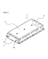
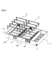
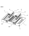
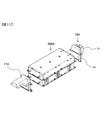
電源装置1は、電動発電機103が回生時に発生した電力及び発電機102が発生した電力を電動発電機103の駆動用電力として充電し、電動発電機103の駆動時、この駆動に必要な電力を放電する駆動用車載電源であり、高電圧、例えば600v以上の定格電圧を有するように、数百本のリチウムイオン電池により構成されたバッテリシステムである。
The power supply device 1 charges the electric power generated when the motor generator 103 is regenerated and the electric power generated by the generator 102 as driving electric power for the motor generator 103. When the motor generator 103 is driven, the electric power necessary for this driving is charged. Is a battery system composed of several hundreds of lithium ion batteries so as to have a high voltage, for example, a rated voltage of 600 V or higher.
尚、電源装置1の詳細な構成については後述する。
The detailed configuration of the power supply device 1 will be described later.
電源装置1には、電動発電機103および発電機102の他に、車載補機(たとえばパワーステアリング装置,エアーブレーキ)に動力を供給する電動アクチュエータ、電源装置1よりも定格電圧が低く、車内電装品(たとえばライト,オーディオ、車載電子制御装置)に駆動電力を供給する電装用電源である低圧バッテリなどがDC/DCコンバータを介して電気的に接続されている。DC/DCコンバータは、電源装置1の出力電圧を降圧して電動アクチュエータや低圧バッテリなどに供給したり、低圧バッテリの出力電圧を昇圧して電源装置1などに供給したりする昇降圧装置であり、電源装置1と同じ筐体内に収納されている場合もある。低圧バッテリには定格電圧24vの鉛バッテリを用いている。低圧バッテリとしては、同じ定格電圧を有するリチウムイオンバッテリ或いはニッケル水素バッテリを用いてもよい。
In addition to the motor generator 103 and the generator 102, the power supply device 1 includes an electric actuator that supplies power to an in-vehicle auxiliary device (for example, a power steering device, an air brake), a rated voltage lower than that of the power supply device 1, and A low-voltage battery or the like, which is an electric power supply for supplying driving power to a product (for example, a light, an audio, or an on-vehicle electronic control device), is electrically connected via a DC / DC converter. The DC / DC converter is a step-up / step-down device that steps down the output voltage of the power supply device 1 and supplies it to an electric actuator or a low-voltage battery, or boosts the output voltage of the low-voltage battery and supplies it to the power supply device 1 or the like. In some cases, the power supply device 1 is housed in the same housing. A lead battery having a rated voltage of 24v is used as the low voltage battery. As the low voltage battery, a lithium ion battery or a nickel metal hydride battery having the same rated voltage may be used.
電動発電機103,第1及び第2電力変換装置105,106,発電機102,エンジン101及び変速機107は、車両の床下のデファレンシャルギア108の近傍に配置されている。電源装置1は、ノンステップ式或いは低床式のハイブリッドバス、ハイブリッド電車の場合には、車両の屋根に設けられた収納部に配置される。この場合、収納部は、屋根から上方に突起するように形成される。また、電源装置1は、ステップ付きの高床式のハイブリッドバス、ハイブリッドトラックの場合には、車両の床下かつ第1及び第2電力変換装置105,106の近傍に配置される。第1及び第2電力変換装置105,106の近傍に電源装置1を設けることにより、第1及び第2電力変換装置105,106と電源装置1との間の電気配線長を短くでき、インダクタンスを低減できる。
The motor generator 103, the first and second power converters 105 and 106, the generator 102, the engine 101, and the transmission 107 are disposed in the vicinity of the differential gear 108 under the vehicle floor. In the case of a non-step type or low-floor type hybrid bus or hybrid train, the power supply device 1 is disposed in a storage portion provided on the roof of the vehicle. In this case, the storage portion is formed so as to protrude upward from the roof. Further, in the case of a stilt hybrid bus or hybrid truck with steps, the power supply device 1 is disposed under the floor of the vehicle and in the vicinity of the first and second power converters 105 and 106. By providing the power supply device 1 in the vicinity of the first and second power conversion devices 105 and 106, the electrical wiring length between the first and second power conversion devices 105 and 106 and the power supply device 1 can be shortened, and the inductance can be reduced. Can be reduced.
ハイブリッド自動車100の力行時(発進、加速、通常走行など)、モータコントローラ110に正のトルク指令が与えられて第2電力変換装置106の作動が制御されると、電源装置1に蓄電された直流電力は第2電力変換装置106により三相交流電力に変換されて電動発電機103に供給される。これにより、電動発電機103が駆動されて回転動力が発生する。発生した回転動力は変速機107及びデファレンシャルギア108を介して車軸109に伝達され、駆動輪104を駆動する。この駆動により、電源装置1の蓄電量が減少した場合にはエンジン101の作動によって発電機102を駆動し、三相交流電力を発生させる。発生した三相交流電力は第1電力変換装置105によって直流電力に変換され、電源装置1に充電される。
When the hybrid vehicle 100 is powered (starting, accelerating, normal traveling, etc.), when a positive torque command is given to the motor controller 110 and the operation of the second power converter 106 is controlled, the direct current stored in the power supply device 1 is stored. The electric power is converted into three-phase AC power by the second power converter 106 and supplied to the motor generator 103. As a result, the motor generator 103 is driven to generate rotational power. The generated rotational power is transmitted to the axle 109 via the transmission 107 and the differential gear 108 to drive the drive wheels 104. When the amount of power stored in the power supply device 1 decreases due to this driving, the generator 102 is driven by the operation of the engine 101 to generate three-phase AC power. The generated three-phase AC power is converted into DC power by the first power converter 105 and charged into the power supply device 1.
ハイブリッド自動車100の回生時(減速、制動など)、モータコントローラ110に負のトルク指令が与えられて第2電力変換装置106の作動が制御されると、駆動輪104の回転動力により駆動される電動発電機2から発生した三相交流電力は直流電力に変換されて電源装置1に供給される。これにより、変換された直流電力は電源装置1に充電される。
At the time of regeneration of the hybrid vehicle 100 (deceleration, braking, etc.), when a negative torque command is given to the motor controller 110 and the operation of the second power conversion device 106 is controlled, the electric drive driven by the rotational power of the drive wheels 104 Three-phase AC power generated from the generator 2 is converted into DC power and supplied to the power supply device 1. Thereby, the converted DC power is charged in the power supply device 1.
モータコントローラ110は、上位制御装置から出力されたトルク指令値から電流指令値を演算すると共に、電流指令値と、電動発電機102と第2電力変換装置106との間を流れる実電流との差分に基づいて電圧指令値を演算し、この演算された電圧指令値に基づいてPWM(パルス幅変調)信号を発生させ、そのPWM信号を第1及び第2電力変換装置105,106に出力する。
The motor controller 110 calculates a current command value from the torque command value output from the host control device, and difference between the current command value and the actual current flowing between the motor generator 102 and the second power converter 106. Based on the voltage command value, a PWM (pulse width modulation) signal is generated based on the calculated voltage command value, and the PWM signal is output to the first and second power converters 105 and 106.
<電源装置1の全体構成>
次に、図14を用いて、電源装置1の全体構成について説明する。
図14は、電源装置1の電気的な回路構成を示す。
電源装置1は、前述したように、電動発電機103を駆動するための車載電源であり、第2電力変換装置106を介して電動発電機103に電気的に接続され、第2電力変換装置106によって充放電が制御される。電源装置1は、大別すると、統括バッテリ制御装置(上位バッテリ制御装置)200、8個のモジュール電池セット500の直並列接続体から構成された電池モジュール部600、及び電池モジュール部600とパワーモジュール111との間の電気的な接続を制御するためのリレー部300から構成されている。
<Overall configuration of power supply 1>
Next, the overall configuration of the power supply device 1 will be described with reference to FIG.
FIG. 14 shows an electrical circuit configuration of the power supply device 1.
As described above, the power supply device 1 is an in-vehicle power supply for driving the motor generator 103, and is electrically connected to the motor generator 103 via the second power conversion device 106, and the second power conversion device 106. Is used to control charging and discharging. The power supply device 1 can be broadly divided into a general battery control device (upper battery control device) 200, a battery module unit 600 composed of a series-parallel connection of eight module battery sets 500, and a battery module unit 600 and a power module 111 is configured with a relay unit 300 for controlling electrical connection with 111.
第2電力変換装置106は、前述した電力変換(直流電力を三相交流電力に変換或いは三相交流電力を直流電力に変換)をスイッチング半導体素子の作動(オン・オフ)によって制御する電子機器であり、パワーモジュール111と、ドライバー装置112とを備えている。
The second power converter 106 is an electronic device that controls the above-described power conversion (converting DC power into three-phase AC power or converting three-phase AC power into DC power) by operating a switching semiconductor element (ON / OFF). The power module 111 and the driver device 112 are provided.
パワーモジュール111は、前述した電力変換回路を構成する部位であり、電池モジュール部600の正負極端子にリレー部300を介して直流正負極側が電気的に接続され、ドライバー装置112から出力された6アーム分(6つのスイッチング半導体素子分)の駆動信号によりスイッチング(オン・オフ)動作し、電池モジュール部600から出力された直流電力を三相交流電力に変換して電動発電機103に出力する、或いは電動発電機103から出力された三相交流電力を直流電力に変換して電源装置1に出力する。
The power module 111 is a part constituting the above-described power conversion circuit, and the DC positive / negative electrode side is electrically connected to the positive / negative terminal of the battery module unit 600 via the relay unit 300, and is output from the driver device 112. Switching (on / off) operation is performed by driving signals for the arms (for six switching semiconductor elements), and the DC power output from the battery module unit 600 is converted into three-phase AC power and output to the motor generator 103. Alternatively, the three-phase AC power output from the motor generator 103 is converted into DC power and output to the power supply device 1.
ドライバー装置112は、モータコントローラ110から出力された指令信号(PWM信号)に基づいて、パワーモジュール111を作動させるための駆動信号を生成し、この生成された駆動信号を六つのスイッチング半導体素子のゲート電極に出力する。六つのスイッチング半導体素子は、ドライバー装置112から出力された駆動信号に基づいてオン・オフする。
The driver device 112 generates a drive signal for operating the power module 111 based on the command signal (PWM signal) output from the motor controller 110, and uses the generated drive signal as a gate of six switching semiconductor elements. Output to electrode. The six switching semiconductor elements are turned on / off based on the drive signal output from the driver device 112.
リレー部300は、正極側メインコンタクタ310、負極側メインコンタクタ320、正極側プリチャージコンタクタ330、及び正極側プリチャージ抵抗340を備えている。正極側メインコンタクタ310、負極側メインコンタクタ320、正極側プリチャージコンタクタ330の開閉は、上位制御装置から出力された開閉指令信号に基づいて統括バッテリ制御装置200が制御する。
The relay unit 300 includes a positive side main contactor 310, a negative side main contactor 320, a positive side precharge contactor 330, and a positive side precharge resistor 340. The overall battery control device 200 controls the opening and closing of the positive side main contactor 310, the negative side main contactor 320, and the positive side precharge contactor 330 based on an opening / closing command signal output from the host controller.
正極側メインコンタクタ310の固定接点の一方側には電池モジュール部600の正極側が電気的に接続され、その他方側にはパワーモジュール111の正極側が強電ケーブルを介して電気的に接続されている。負極側メインコンタクタ320の固定接点の一方側には電池モジュール部600の負極側が電気的に接続され、その他方側にはパワーモジュール111の負極側が強電ケーブルを介して電気的に接続されている。正極側メインコンタクタ310の固定接点間には、正極側プリチャージコンタクタ330と正極側プリチャージ抵抗340とを電気的に直列に接続した正極側プリチャージ回路が電気的に並列に接続されている。
The positive side of the battery module unit 600 is electrically connected to one side of the fixed contact of the positive side main contactor 310, and the positive side of the power module 111 is electrically connected to the other side via a high voltage cable. The negative electrode side of the battery module unit 600 is electrically connected to one side of the fixed contact of the negative electrode side main contactor 320, and the negative electrode side of the power module 111 is electrically connected to the other side via a high voltage cable. A positive side precharge circuit in which a positive side precharge contactor 330 and a positive side precharge resistor 340 are electrically connected in series is electrically connected in parallel between fixed contacts of the positive side main contactor 310.
プリチャージコンタクタは、メインコンタクタの投入前に投入され、パワーモジュール111に電気的に並列に接続された平滑コンデンサを充電するために用いられる。これは、第2電力変換装置106の動作開始時、平滑コンデンサの電荷が略ゼロであり、この状態でメインコンタクタを投入すると、電池モジュール部600から第2電力変換装置106に向かって大きな初期電流が流れ込み、メインコンタクタ(特に正極側)の固定接点と可動接点が融着して破損する恐れがある。このため、メインコンタクタに対して電気的に並列にプリチャージ回路を設け、第2電力変換装置106の動作開始時、まず、プリチャージコンタクタを投入して平滑コンデンサを充電する。平滑コンデンサが所定の電圧まで充電されたら、メインコンタクタを投入してプリチャージコンタクタを開放する。これにより、メインコンタクタに流れる電流を許容電流以下にできるので、メインコンタクタを大電流から保護できると共に、電池モジュール部600及び第2電力変換装置106を流れる最大電流を許容最大電流以下に低減できる。
The precharge contactor is charged before charging the main contactor and is used to charge a smoothing capacitor electrically connected to the power module 111 in parallel. This is because the charge of the smoothing capacitor is substantially zero at the start of the operation of the second power conversion device 106, and when the main contactor is turned on in this state, a large initial current flows from the battery module unit 600 toward the second power conversion device 106. May flow and the fixed contact and the movable contact of the main contactor (especially the positive electrode side) may be fused and damaged. For this reason, a precharge circuit is provided in parallel with the main contactor, and when the operation of the second power converter 106 is started, first, the precharge contactor is turned on to charge the smoothing capacitor. When the smoothing capacitor is charged to a predetermined voltage, the main contactor is turned on to open the precharge contactor. As a result, the current flowing through the main contactor can be reduced below the allowable current, so that the main contactor can be protected from a large current, and the maximum current flowing through the battery module unit 600 and the second power conversion device 106 can be reduced below the allowable maximum current.
電池モジュール部600は、8個のモジュール電池セット500が電気的に直並列に接続されて構成された蓄電部であり、高電位側の電池モジュールブロックと低電位側の電池モジュールブロックとを備えている。高電位側の電池モジュールブロックは、4個のモジュール電池セット500が電気的に並列に接続されて構成されている。低電位側の電池モジュールブロックも同様に、4個のモジュール電池セット500が電気的に並列に接続されて構成されている。高電位側の電池モジュールブロックの負極側と低電位側の電池モジュールブロックの正極側は保守・点検用のSD(サービスディスコネクト)スイッチ700を介して電気的に直列に接続されている。SDスイッチ700は、スイッチ710とヒューズ720とを電気的に直列に接続した回路から構成されている。
The battery module unit 600 is a power storage unit configured by electrically connecting eight module battery sets 500 in series and parallel, and includes a battery module block on the high potential side and a battery module block on the low potential side. Yes. The battery module block on the high potential side is configured by electrically connecting four module battery sets 500 in parallel. Similarly, the battery module block on the low potential side includes four module battery sets 500 electrically connected in parallel. The negative electrode side of the battery module block on the high potential side and the positive electrode side of the battery module block on the low potential side are electrically connected in series via an SD (service disconnect) switch 700 for maintenance / inspection. The SD switch 700 includes a circuit in which a switch 710 and a fuse 720 are electrically connected in series.
各モジュール電池セット500は、単位電池モジュール510、及び単位電池モジュール510の状態を管理及び制御するためのモジュール電池セット制御装置520を備えている。
Each module battery set 500 includes a unit battery module 510 and a module battery set controller 520 for managing and controlling the state of the unit battery module 510.
単位電池モジュール510は二つの単位電池ブロック(或いは単位電池パック)、すなわち高電位側単位電池ブロック510a及び低電位側単位電池ブロック510bを電気的に直列に接続したものから構成されている。各単位電池ブロックには組電池が収納されている。各組電池は、複数のリチウム単電池(リチウムセル)を電気的に直列に接続したものから構成されている。
The unit battery module 510 includes two unit battery blocks (or unit battery packs), that is, a unit in which a high potential unit battery block 510a and a low potential unit battery block 510b are electrically connected in series. Each unit battery block contains an assembled battery. Each assembled battery is composed of a plurality of lithium single batteries (lithium cells) electrically connected in series.
モジュール電池セット制御装置520は、統括バッテリコントローラ200に対して下位に相当する下位バッテリコントローラ530、及び下位バッテリコントローラ530に対して下位に相当するセルコントローラ540から構成されている。
The module battery set control device 520 includes a lower battery controller 530 corresponding to a lower level with respect to the overall battery controller 200 and a cell controller 540 corresponding to a lower level with respect to the lower battery controller 530.
下位バッテリコントローラ530は、単位電池モジュール510の状態を管理及び制御すると共に、統括バッテリコントローラ200に単位電池モジュール510の状態などを通知するためのものである。単位電池モジュール510の状態の管理及び制御には、単位電池モジュール510の総電圧、総電流、温度などの計測、単位電池モジュール510の蓄電状態(SOC)、劣化状態(SOH)などの演算、セルコントローラ540に対する指令の出力などがある。
The lower battery controller 530 manages and controls the state of the unit battery module 510 and notifies the general battery controller 200 of the state of the unit battery module 510 and the like. For management and control of the state of the unit battery module 510, measurement of the total voltage, total current, temperature, etc. of the unit battery module 510, calculation of the storage state (SOC), deterioration state (SOH), etc. of the unit battery module 510, cell There is a command output to the controller 540 and the like.
単位電池モジュール510の充放電電流は、単位電池モジュール510の正極側に電気的に直列に接続された電流センサからの出力信号に基づいて下位バッテリコントローラ530が検出する。単位電池モジュール510の総電圧は、単位電池モジュール510の正負極間に電気的に並列に接続された電圧センサの出力信号に基づいて下位バッテリコントローラ530が検出する。各下位バッテリコントローラによって検出された総電圧、充放電電流は統括バッテリコントローラ200に情報伝達される。
The lower battery controller 530 detects the charging / discharging current of the unit battery module 510 based on an output signal from a current sensor electrically connected in series to the positive electrode side of the unit battery module 510. The lower battery controller 530 detects the total voltage of the unit battery module 510 based on an output signal of a voltage sensor electrically connected in parallel between the positive and negative electrodes of the unit battery module 510. The total voltage and charge / discharge current detected by each lower battery controller are transmitted to the general battery controller 200.
セルコントローラ540は、下位バッテリコントローラ530からの指令によって複数のリチウム単電池の状態を管理及び制御するためのものであり、複数の集積回路(IC)によって構成されている。複数のリチウム単電池の状態の管理及び制御には、各リチウム単電池の電圧の計測、各リチウム単電池の蓄電量の調整などがある。各集積回路は、対応する複数のリチウム単電池が決められており、対応する複数のリチウム単電池に対して状態の管理及び制御を行う。
The cell controller 540 is for managing and controlling the states of a plurality of lithium cells in accordance with commands from the lower battery controller 530, and is composed of a plurality of integrated circuits (ICs). The management and control of the states of the plurality of lithium cells include measurement of the voltage of each lithium cell, adjustment of the amount of electricity stored in each lithium cell. In each integrated circuit, a plurality of corresponding lithium cells are determined, and state management and control are performed on the corresponding plurality of lithium cells.
下位バッテリコントローラ530の電源には、車載補機、例えばライトやオーディオ機器などの電源として搭載された補機用バッテリ(大型の自動車の場合、公称出力電圧12vのバッテリを2個直列に接続した24vのバッテリ)を用いている。このため、下位バッテリコントローラ530には補機用バッテリからの電圧(例えば24v)が印加されている。下位バッテリコントローラ530は、印加された電圧をDC/DCコンバータ(直流−直流変換器)から構成された電源回路によって降圧(例えば5vに降圧)し、この降圧された電圧を、下位バッテリコントローラ530を構成する電子部品に駆動電圧として印加する。これにより、下位バッテリコントローラ530を構成する電子部品は作動する。
The power source of the lower battery controller 530 is an auxiliary battery mounted as a power source for an in-vehicle auxiliary device such as a light or an audio device (in the case of a large vehicle, a 24V battery in which two batteries having a nominal output voltage of 12v are connected in series) Battery). For this reason, the voltage (for example, 24v) from the battery for auxiliary machines is applied to the low-order battery controller 530. The lower battery controller 530 steps down the applied voltage by a power supply circuit composed of a DC / DC converter (DC-DC converter) (for example, steps down to 5 V), and lowers the lower voltage controller 530 to the lower battery controller 530. A drive voltage is applied to the electronic components to be configured. Thereby, the electronic components constituting the lower battery controller 530 operate.
セルコントローラ540を構成する集積回路の電源には、対応する複数のリチウム単電池を用いている。このため、セルコントローラ540と単位電池モジュール510の両者は接続線を介して電気的に接続されている。各集積回路には、対応する複数のリチウム単電池の最高電位の電圧が接続線を介して印加されている。各集積回路は、印加された電圧を電源回路によって降圧(例えば5vに降圧)し、これを動作電源として用いる。
A plurality of corresponding lithium single cells are used as the power source of the integrated circuit constituting the cell controller 540. For this reason, both the cell controller 540 and the unit battery module 510 are electrically connected via a connection line. The voltage of the highest potential of a corresponding plurality of lithium cells is applied to each integrated circuit via a connection line. Each integrated circuit steps down the applied voltage (for example, down to 5 V) by a power supply circuit, and uses this as an operation power supply.
統括バッテリ制御装置200は、電池モジュール部600を構成する8個のモジュール電池セット500のそれぞれと並列に通信を実施して8個のモジュール電池セット500のそれぞれの充電状態や動作状態などを監視すると共に、8個のモジュール電池セット500のそれぞれの充電状態の調整や異常検出などを行う電子回路装置であり、マイクロコンピュータを含む複数の電子回路部品が回路基板に実装されることにより構成されている。また、統括バッテリ制御装置200は、上位制御装置からの指令信号に基づいてリレー部300の開閉を制御する。さらに、統括バッテリ制御装置200は、上位制御装置と通信を実施し、電池モジュール部600から供給できる或いは電池モジュール部600で受け入れられる許容充放電電力或いは許容充放電電流の情報や異常検知結果、電池モジュール部600の充電状態の情報などを上位制御装置に出力すると共に、イグニションキースイッチの作動に基づく起動信号やリレー部300を開閉するための指令信号などを入力する。上位制御装置は、モータコントローラ110、さらにはその上位の車両制御装置などを示す。
The overall battery control device 200 communicates in parallel with each of the eight module battery sets 500 constituting the battery module unit 600 to monitor the charging state, the operating state, etc. of each of the eight module battery sets 500. At the same time, it is an electronic circuit device that adjusts the state of charge of each of the eight module battery sets 500 and detects an abnormality, and is configured by mounting a plurality of electronic circuit components including a microcomputer on a circuit board. . Further, the overall battery control device 200 controls the opening and closing of the relay unit 300 based on a command signal from the host control device. Further, the overall battery control device 200 communicates with the host control device, and information on allowable charge / discharge power or allowable charge / discharge current that can be supplied from the battery module unit 600 or accepted by the battery module unit 600, an abnormality detection result, a battery Information on the state of charge of the module unit 600 is output to the host controller, and an activation signal based on the operation of the ignition key switch, a command signal for opening and closing the relay unit 300, and the like are input. The host control device indicates the motor controller 110 and the host vehicle control device.
また、統括バッテリ制御装置200はリーク検出器400を備えている。リーク検出器400はリレー部300とパワーモジュール111との間に設けられ、電池モジュール部600と車体アースとの間におけるリークの有無を検出するための電気回路であり、直流正負極と車体アースとの間に半導体スイッチを介して電気的に接続された抵抗分圧回路を備えている。統括バッテリ制御装置200は、半導体スイッチを制御して抵抗分圧回路を直流正負極と車体アースとの間に電気的に接続すると共に、その接続によって抵抗分圧回路から得られる電圧情報を読み込み、電池モジュール部600と車体アースとの間におけるリークの有無を判断する。リークが有る場合、統括バッテリ制御装置200は、その旨を上位制御装置に通知すると共に、運転席の警告灯の点灯や音声通知によって運転者に警告を発する。これにより、必要な安全措置を講じた状態で車両を安全に駆動させることができるとともに、サービスセンタにおける早期点検・修理を運転者に促すことができる。
The overall battery control apparatus 200 includes a leak detector 400. The leak detector 400 is an electric circuit that is provided between the relay unit 300 and the power module 111 and detects the presence or absence of a leak between the battery module unit 600 and the vehicle body ground. A resistor voltage divider circuit electrically connected via a semiconductor switch is provided. The overall battery control device 200 controls the semiconductor switch to electrically connect the resistance voltage dividing circuit between the DC positive and negative electrodes and the vehicle body ground, and reads voltage information obtained from the resistance voltage dividing circuit by the connection, It is determined whether there is a leak between the battery module unit 600 and the vehicle body ground. If there is a leak, the overall battery control device 200 notifies the host control device to that effect, and issues a warning to the driver by turning on a warning light on the driver's seat or by voice notification. As a result, the vehicle can be safely driven in a state where necessary safety measures are taken, and the driver can be encouraged to perform early inspection and repair at the service center.
統括バッテリコントローラ200には、前述したように、イグニションキースイッチから出力された信号が入力されている。イグニションキースイッチから出力された信号は電源装置1の起動及び停止の合図になる。
As described above, the overall battery controller 200 receives the signal output from the ignition key switch. The signal output from the ignition key switch is a signal for starting and stopping the power supply device 1.
イグニションキースイッチがオンになると、統括バッテリコントローラ200では、イグニションキースイッチからの出力信号に基づいて電源回路が動作し、複数の電子回路部品に対して電源回路から駆動電圧が印加される。これにより、複数の電子回路部品が動作し、統括バッテリコントローラ200が起動する。統括バッテリコントローラ200が起動すると、各下位バッテリコントローラ530に対してパラレルに統括バッテリコントローラ200から起動信号が出力される。各下位バッテリコントローラ530では、起動信号に基づいて電源回路が動作し、複数の電子回路部品に対して電源回路から駆動電圧が印加される。これにより、複数の電子回路部品が動作し、各下位バッテリコントローラ530が起動する。
When the ignition key switch is turned on, in the overall battery controller 200, the power supply circuit operates based on the output signal from the ignition key switch, and the drive voltage is applied from the power supply circuit to a plurality of electronic circuit components. Thereby, a plurality of electronic circuit components operate, and the overall battery controller 200 is activated. When the overall battery controller 200 is activated, an activation signal is output from the overall battery controller 200 to each lower battery controller 530 in parallel. In each lower battery controller 530, the power supply circuit operates based on the activation signal, and the drive voltage is applied from the power supply circuit to the plurality of electronic circuit components. Thereby, a plurality of electronic circuit components operate, and each lower battery controller 530 is activated.
各下位バッテリコントローラ530が起動すると、対応するセルコントローラ540に対して下位バッテリコントローラ530から起動信号が出力される。セルコントローラ540では、起動指令に基づいて複数の集積回路の電源回路が順次動作する。これにより、複数の集積回路が順次起動し、セルコントローラ540が起動する。セルコントローラ540の起動後、各モジュール電池セット500では、所定の初期処理が実行され、電源装置1の起動が完了する。上位制御装置への完了報告は統括バッテリコントローラ200から出力される。
When each lower battery controller 530 is activated, an activation signal is output from the lower battery controller 530 to the corresponding cell controller 540. In the cell controller 540, the power supply circuits of a plurality of integrated circuits operate sequentially based on the start command. As a result, the plurality of integrated circuits are sequentially activated, and the cell controller 540 is activated. After activation of the cell controller 540, in each module battery set 500, predetermined initial processing is executed, and activation of the power supply device 1 is completed. A completion report to the host controller is output from the overall battery controller 200.
所定の初期処理としては、例えば各リチウム単電池の電圧の測定、異常診断、単位電池モジュール510全体の電圧、電流、温度の測定、単位電池モジュール510の蓄電状態、劣化状態の演算などがある。
Examples of the predetermined initial processing include measurement of voltage of each lithium cell, abnormality diagnosis, measurement of voltage, current, and temperature of the entire unit battery module 510, calculation of the storage state and deterioration state of the unit battery module 510, and the like.
イグニションキースイッチがオフになると、統括バッテリコントローラ200から各下位バッテリコントローラ530に対してパラレルに停止信号が出力される。各下位バッテリコントローラ530は、停止信号を受けると、対応するセルコントローラ540に対して停止信号を出力する。これにより、各モジュール電池セット500では、所定の終了処理が実行される。所定の終了処理が終了すると、まず、セルコントローラ540の各集積回路の電源回路がオフする。これにより、セルコントローラ540が停止する。対応するセルコントローラ540が停止し、セルコントローラ540との間において通信ができなくなると、各下位バッテリコントローラ530の電源回路の動作が停止し、複数の電子回路部品の動作が停止する。これにより、バッテリコントローラ530が停止する。各下位バッテリコントローラ530が停止し、各下位バッテリコントローラ530との間において通信ができなくなると、統括バッテリコントローラ200の電源回路の動作が停止し、複数の電子回路部品の動作が停止する。これにより、統括バッテリコントローラ200が停止し、電源装置1が停止する。
When the ignition key switch is turned off, a stop signal is output from the overall battery controller 200 to each lower battery controller 530 in parallel. When each lower battery controller 530 receives a stop signal, it outputs a stop signal to the corresponding cell controller 540. Thereby, in each module battery set 500, a predetermined end process is executed. When the predetermined end process ends, first, the power supply circuit of each integrated circuit of the cell controller 540 is turned off. Thereby, the cell controller 540 stops. When the corresponding cell controller 540 stops and communication with the cell controller 540 becomes impossible, the operation of the power supply circuit of each lower battery controller 530 is stopped, and the operation of a plurality of electronic circuit components is stopped. Thereby, the battery controller 530 stops. When each lower battery controller 530 stops and communication with each lower battery controller 530 becomes impossible, the operation of the power supply circuit of the overall battery controller 200 stops, and the operation of a plurality of electronic circuit components stops. As a result, the overall battery controller 200 stops and the power supply device 1 stops.
所定の終了処理としては、例えば各リチウム単電池の電圧の測定、各リチウム単電池の蓄電量の調整などがある。
Examples of the predetermined termination process include measurement of the voltage of each lithium cell and adjustment of the amount of power stored in each lithium cell.
統括バッテリコントローラ200とモータコントローラ110などの上位制御装置との間の情報伝達、及び統括バッテリコントローラ200と各下位バッテリコントローラ530との間の情報伝達には、車載ローカルエリアネットワークによる通信を用いている。下位バッテリコントローラ530とセルコントローラ540との間の情報伝達にはLIN通信を用いている。
Communication via the in-vehicle local area network is used for information transmission between the overall battery controller 200 and the host controller such as the motor controller 110, and information transmission between the overall battery controller 200 and each lower battery controller 530. . LIN communication is used for information transmission between the lower battery controller 530 and the cell controller 540.
リレー部300による電気的な導通及び遮断は、モータコントローラ110から出力された指令信号を受けて統括バッテリコントローラ200が制御する。モータコントローラ110は、車載電機システムの起動時には、電源装置1の起動完了の通知を統括バッテリコントローラ200から受けることにより、統括バッテリコントローラ200に対してリレー部300の導通の指令信号を出力する。統括バッテリコントローラ200は指令信号に基づいてリレー部300の動作電源に対して駆動信号を出力し、リレー部300が導通するように制御する。また、モータコントローラ110は、車載電機システムの停止時及び車載電機システムの異常時には、イグニションキースイッチからオフの出力信号或いは異常信号を受けることにより、統括バッテリコントローラ200に対してリレー部300の遮断の指令信号を出力する。統括バッテリコントローラ200は指令信号に基づいてリレー部300の動作電源に対して駆動信号出力し、リレー部300が導通するように制御する。リレー部140に対して遮断の指令信号を出力し、リレー部300が遮断するように制御する。
The overall battery controller 200 controls electrical continuity and interruption by the relay unit 300 in response to a command signal output from the motor controller 110. The motor controller 110 outputs a command signal for continuity of the relay unit 300 to the overall battery controller 200 by receiving a notification of completion of activation of the power supply device 1 from the overall battery controller 200 when the on-vehicle electric system is activated. The overall battery controller 200 outputs a drive signal to the operating power supply of the relay unit 300 based on the command signal, and controls the relay unit 300 to be conductive. Further, the motor controller 110 receives an output signal or an abnormality signal from the ignition key switch when the on-vehicle electric system is stopped or when the on-vehicle electric system is abnormal, thereby blocking the relay unit 300 from the overall battery controller 200. A command signal is output. The general battery controller 200 outputs a drive signal to the operating power supply of the relay unit 300 based on the command signal, and controls the relay unit 300 to be conductive. A control signal is output to the relay unit 140 so that the relay unit 300 is disconnected.
車載電機システムの起動時にあたっては、まず、負極側メインコンタクタ320が投入され、この後、プリチャージコンタクタ330が投入される。これにより、電池モジュール部600から供給された電流が抵抗340によって制限された後、第2電力変換装置106の平滑コンデンサに供給され、平滑コンデンサが充電される。平滑コンデンサが所定の電圧まで充電された後、正極側メインコンタクタ310が投入され、プリチャージコンタクタ330が開放される。これにより、電池モジュール部600から正極側メインコンタクタ310を介してパワーモジュール111に主電流が供給されるが、この時の主電流は、正極側メインコンタクタ310及び平滑コンデンサの許容電流以下になる。従って、車載電機システムの起動時、平滑コンデンサの電荷が略ゼロにあることに起因して、電池モジュール部600から瞬間的に大きな初期電流が第2電力変換装置106に流れ込み、平滑コンデンサが高発熱して損傷する、正極側メインコンタクタ310の固定接点と可動接点とが融着するなどの異常を招くことがなく、平滑コンデンサ及び正極側メインコンタクタ310を大きな電流から保護できる。
When starting the in-vehicle electric system, first, the negative-side main contactor 320 is turned on, and then the precharge contactor 330 is turned on. Thereby, after the current supplied from the battery module unit 600 is limited by the resistor 340, the current is supplied to the smoothing capacitor of the second power converter 106, and the smoothing capacitor is charged. After the smoothing capacitor is charged to a predetermined voltage, the positive side main contactor 310 is turned on, and the precharge contactor 330 is opened. As a result, the main current is supplied from the battery module unit 600 to the power module 111 via the positive-side main contactor 310. At this time, the main current is less than the allowable current of the positive-side main contactor 310 and the smoothing capacitor. Therefore, when the on-vehicle electric system is started, due to the electric charge of the smoothing capacitor being substantially zero, a large initial current instantaneously flows from the battery module unit 600 to the second power converter 106, and the smoothing capacitor generates high heat. Thus, the smoothing capacitor and the positive side main contactor 310 can be protected from a large current without causing an abnormality such as the fixed contact and the movable contact of the positive side main contactor 310 being fused.
尚、統括バッテリコントローラ200、下位バッテリコントローラ530、セルコントローラ540の各コントローラで扱う情報をまとめておくことにする。
Information handled by each controller of the overall battery controller 200, the lower battery controller 530, and the cell controller 540 is collected.
セルコントローラ540は、各リチウム単電池の電圧を検出し、この検出された電圧を対応する下位バッテリコントローラ530に情報伝達する。また、セルコントローラ540は、リチウム単電池或いは自己の内部回路に異常がある時には、異常フラグ及び異常内容を対応する下位バッテリコントローラ540に情報伝達する。
The cell controller 540 detects the voltage of each lithium cell and transmits the detected voltage to the corresponding lower battery controller 530. In addition, when there is an abnormality in the lithium cell or its own internal circuit, the cell controller 540 transmits information on the abnormality flag and the abnormality content to the corresponding lower battery controller 540.
下位バッテリコントローラ530は、対応するセルコントローラ540から情報伝達された各リチウム単電池の電圧、電圧センサから伝達された電圧検出値、電流センサから伝達された電流検出値、単位電池モジュール510内部に設けられた複数の温度センサ(例えばサーミスタ)から伝達された温度検出値を入力情報とすると共に、予め記憶されているリチウム単電池の初期情報及び入力情報に基づいて、対応する単位電池モジュール510の蓄電量(SOC)、劣化状態(SOH)、充放電許容電流、総電圧、充放電電流、温度の最大最小値、セル電圧の最大最小値を演算或いは検出し、それらを統括バッテリコントローラ200に情報伝達する。
The lower battery controller 530 is provided inside the unit battery module 510, the voltage of each lithium cell transmitted from the corresponding cell controller 540, the voltage detection value transmitted from the voltage sensor, the current detection value transmitted from the current sensor. The temperature detection values transmitted from the plurality of temperature sensors (for example, thermistors) are used as input information, and the power storage of the corresponding unit battery module 510 is performed based on the initial information and input information of the lithium cell stored in advance. Calculates or detects quantity (SOC), deterioration state (SOH), allowable charge / discharge current, total voltage, charge / discharge current, maximum / minimum value of temperature, and maximum / minimum value of cell voltage, and transmits them to general battery controller 200 To do.
統括バッテリコントローラ200は、各下位バッテリコントローラ530から情報伝達された蓄電量(SOC)、劣化状態(SOH)、充放電許容電流、総電圧、充放電電流、温度の最大最小値、セル電圧の最大最小値を入力情報とすると共に、入力情報に基づいて、電池モジュール部600の蓄電量(SOC)、充放電電流抑制率或いは許容充放電電力若しくは許容充放電電流、総電圧、充放電電流、温度、リチウム単電池電圧、劣化状態(SOH)を演算し、それらを上位制御装置に情報伝達する。
The overall battery controller 200 includes a storage amount (SOC), a deterioration state (SOH), a charge / discharge allowable current, a total voltage, a charge / discharge current, a maximum / minimum temperature, and a maximum cell voltage transmitted from each lower battery controller 530. The minimum value is set as the input information, and based on the input information, the storage amount (SOC) of the battery module unit 600, the charge / discharge current suppression rate, the allowable charge / discharge power or the allowable charge / discharge current, total voltage, charge / discharge current, temperature The lithium cell voltage and the deterioration state (SOH) are calculated, and the information is transmitted to the host controller.
ここで、電池モジュール部600の蓄電量(SOC)は、各下位バッテリコントローラ530から情報伝達された各単位電池モジュール510の蓄電量(SOC)の平均値である。電池モジュール部600の充放電電流抑制率或いは許容充放電電力若しくは許容充放電電流は、各下位バッテリコントローラ530から情報伝達された充放電許容電流、セル電圧の最大最小値、演算された電池モジュール部600の蓄電量(SOC)などの情報に基づいて演算される。電池モジュール部600の総電圧は、高電位側の電池モジュールブロックに属する単位電池モジュール510の総電圧の平均値と、低電位側の電池モジュールブロックに属する単位電池モジュール510の総電圧の平均値とを足し合わせた値である。電池モジュール部600の充電電流は、高電位側の電池モジュールブロックに属する単位電池モジュール510の充電電流の総和と、低電位側の電池モジュールブロックに属する単位電池モジュール510の充電電流の総和とのうちの最小値である。電池モジュール部600の放電電流は、高電位側の電池モジュールブロックに属する単位電池モジュール510の放電電流の総和と、低電位側の電池モジュールブロックに属する単位電池モジュール510の放電電流の総和とのうちの最小値である。電池モジュール部600の温度は、各下位バッテリコントローラ530から情報伝達された各単位電池モジュール510の最高値及び最低値である。電池モジュール部600のセル電圧は、各下位バッテリコントローラ530から情報伝達された各単位電池モジュール510のセル電圧のうちの最高値及び最低値である。電池モジュール部600の劣化状態(SOH)は、各下位バッテリコントローラ530から情報伝達された各単位電池モジュール510の劣化状態(SOH)のうちの最高値及び最低値である。
Here, the storage amount (SOC) of the battery module unit 600 is an average value of the storage amount (SOC) of each unit battery module 510 transmitted from each lower battery controller 530. The charging / discharging current suppression rate or the allowable charging / discharging power or the allowable charging / discharging current of the battery module unit 600 includes the charge / discharge allowable current transmitted from each lower battery controller 530, the maximum / minimum value of the cell voltage, and the calculated battery module unit It is calculated based on information such as 600 stored amount (SOC). The total voltage of the battery module unit 600 includes an average value of the total voltage of the unit battery modules 510 belonging to the battery module block on the high potential side and an average value of the total voltages of the unit battery modules 510 belonging to the battery module block on the low potential side. Is the sum of The charging current of the battery module unit 600 is the sum of the charging currents of the unit battery modules 510 belonging to the high potential side battery module block and the sum of the charging currents of the unit battery modules 510 belonging to the low potential side battery module block. Is the minimum value. The discharge current of the battery module unit 600 is the sum of the discharge currents of the unit battery modules 510 belonging to the battery module block on the high potential side and the sum of the discharge currents of the unit battery modules 510 belonging to the battery module block on the low potential side. Is the minimum value. The temperature of the battery module unit 600 is the highest value and the lowest value of each unit battery module 510 transmitted from each lower battery controller 530. The cell voltage of the battery module unit 600 is the highest value and the lowest value among the cell voltages of each unit battery module 510 transmitted from each lower battery controller 530. The deterioration state (SOH) of the battery module unit 600 is the highest value and the lowest value among the deterioration states (SOH) of each unit battery module 510 transmitted from each lower battery controller 530.
<モジュール電池セット制御装置の構成>
次に、図15を用いて、モジュール電池セット制御装置520について説明する。
図15は、モジュール電池セット制御装置520の電気的な接続構成を示す。
モジュール電池セット制御装置520のうち、下位バッテリコントローラ530は、マイクロコンピュータ531(以下、「マイコン531」と略称する)を含む複数の電子回路部品により構成されている。それらの電子回路部品は回路基板532に実装され、対応する単位電池モジュール510とは別体の筐体に収納されている。下位バッテリコントローラ530を収納した筐体は、制御用電子回路として、対応する単位電池モジュール510の近傍に配置されている。
<Configuration of module battery set control device>
Next, the module battery set control device 520 will be described with reference to FIG.
FIG. 15 shows an electrical connection configuration of the module battery set control device 520.
Of the module battery set control device 520, the lower battery controller 530 is composed of a plurality of electronic circuit components including a microcomputer 531 (hereinafter simply referred to as “microcomputer 531”). These electronic circuit components are mounted on a circuit board 532 and housed in a housing separate from the corresponding unit battery module 510. The housing that houses the lower battery controller 530 is disposed in the vicinity of the corresponding unit battery module 510 as a control electronic circuit.
セルコントローラ540は、リチウム単電池511に電気的に接続された24個の集積回路(IC)541A〜541Xを含む複数の電子回路部品により構成されている。それらの電子回路部品は、単位電池ブロック510a,510bに応じて、対応する回路基板542a、542bに分けられて実装されている。回路基板542a、542bは、対応する単位電池ブロック510a、510bの筐体に収納されていると共に、筐体の長手方向一方側端部に配置されている。
The cell controller 540 includes a plurality of electronic circuit components including 24 integrated circuits (ICs) 541A to 541X that are electrically connected to the lithium cell 511. These electronic circuit components are divided and mounted on corresponding circuit boards 542a and 542b according to the unit battery blocks 510a and 510b. The circuit boards 542a and 542b are housed in the housings of the corresponding unit battery blocks 510a and 510b, and are arranged at one end in the longitudinal direction of the housing.
また、セルコントローラ540は複数の抵抗543及び複数のフォトカプラ544などの複数の回路素子を備えている。抵抗543は、リチウム単電池511の充電量を調整する際に用いられ、リチウム単電池511から放出された電流を熱に変換して消費する消費用回路素子であり、各集積回路541A〜541Xに対して四つ(R1〜R4)ずつ設けられている。フォトカプラ544は、集積回路541A〜541Xのうちの最始端にあたる集積回路541Aとマイコン531との間、及び集積回路541A〜541Xのうちの最終端にあたる集積回路541Xとマイコン531との間の信号伝送路に設けられたインターフェース回路素子であり、集積回路541A,541Xとマイコン531との間において、電位レベルの異なる信号を送受信するための光学的絶縁素子である。
The cell controller 540 includes a plurality of circuit elements such as a plurality of resistors 543 and a plurality of photocouplers 544. The resistor 543 is a circuit element for consumption that is used when adjusting the charge amount of the lithium cell 511, and that converts the current discharged from the lithium cell 511 into heat and consumes it. Each of the integrated circuits 541A to 541X In contrast, four (R1 to R4) are provided. The photocoupler 544 transmits signals between the integrated circuit 541A corresponding to the start of the integrated circuits 541A to 541X and the microcomputer 531 and between the integrated circuit 541X corresponding to the final end of the integrated circuits 541A to 541X and the microcomputer 531. It is an interface circuit element provided on the path, and is an optical insulating element for transmitting and receiving signals having different potential levels between the integrated circuits 541A and 541X and the microcomputer 531.
複数のリチウム単電池511は各集積回路541A〜541Xに対応させて複数のグループに割り振られている。本実施例では、高電位側の単位電池ブロック510aの組電池を構成する48本のリチウム単電池511と、及び低電位側の単位電池ブロック510bの組電池を構成する48本のリチウム単電池511とを合わせた96本のリチウム単電池511を24グループに割り振っている。具体的には、電気的に直列に接続された96本のリチウム単電池511をその接続順にしたがって電位的に上位から順番に4つずつに区切り、24グループを構成している。すなわち電位的に1番目のリチウム単電池511から電位的に4番目のリチウム単電池511までの電気的に直列に接続されたリチウム単電池群を第1グループ、電位的に5番目のリチウム単電池511から電位的に8番目のリチウム単電池511までの電気的に直列に接続されたリチウム単電池群を第2グループ、・・・、電位的に89番目のリチウム単電池511から電位的に92番目のリチウム単電池511までの電気的に直列に接続されたリチウム単電池群を第23グループ、電位的に93番目のリチウム単電池511から電位的に96番目のリチウム単電池511までの電気的に直列に接続されたリチウム単電池群を第24グループというように、96本のリチウム単電池511をグループ分けしている。
The plurality of lithium cells 511 are allocated to a plurality of groups corresponding to the integrated circuits 541A to 541X. In the present embodiment, 48 lithium unit cells 511 constituting the assembled battery of the unit cell block 510a on the high potential side and 48 lithium unit cells 511 constituting the assembled battery of the unit cell block 510b on the low potential side. 96 lithium unit cells 511 including the above are allocated to 24 groups. Specifically, 96 lithium unit cells 511 electrically connected in series are divided into four groups in order from the top in terms of the connection order, thereby forming 24 groups. That is, a group of lithium cells electrically connected in series from the first lithium cell 511 to the fourth lithium cell 511 in potential is the first group, and the fifth lithium cell in potential. A group of lithium cells electrically connected in series from 511 to the eighth lithium cell 511 in potential is a second group,..., A potential 92 from the 89th lithium cell 511 in potential. A group of lithium cells connected in series up to the lithium ion cell 511 is the 23rd group, and the electric potential from the 93th lithium cell 511 to the 96th lithium cell 511 is potential. 96 lithium cell batteries 511 are grouped so that a group of lithium cell cells connected in series is called a 24th group.
尚、本実施例では、各電池ブロック毎に複数のリチウム単電池511を12グループに分けた場合を例に挙げて説明するが、グループの分け方としては、96本のリチウム単電池511を6本ずつ、16グループに分けてもよい。
In this embodiment, a case where a plurality of lithium unit cells 511 are divided into 12 groups for each battery block will be described as an example. However, as a method of grouping, 96 lithium unit cells 511 are divided into 6 groups. Each book may be divided into 16 groups.
集積回路541Aには、接続線548及び基板配線547を介して、第1グループを構成する4つのリチウム単電池511(BC1〜BC4)のそれぞれの正極側及び負極側が電気的に接続されている。これにより、集積回路541Aには、接続線548及び基板配線54を介して、第1グループを構成する4つのリチウム単電池511のそれぞれの端子電圧に基づくアナログ信号が取り込まれる。集積回路541Aは、アナログデジタル変換器を備えており、取り込まれたアナログ信号を順次、デジタル信号に変換し、第1グループを構成する4つのリチウム単電池511の端子電圧を検出する。集積回路541B〜541Xも集積回路541Aの場合と同様に、接続線547及び基板配線548を介して、対応するグループを構成する4つのリチウム単電池511のそれぞれの正極側及び負極側に電気的に接続され、対応するグループを構成する4つのリチウム単電池511のそれぞれの端子電圧を取り込んで検出する。
The positive electrode side and the negative electrode side of each of the four lithium single cells 511 (BC1 to BC4) constituting the first group are electrically connected to the integrated circuit 541A through the connection line 548 and the substrate wiring 547. As a result, the integrated circuit 541A receives analog signals based on the terminal voltages of the four lithium single cells 511 constituting the first group via the connection line 548 and the substrate wiring 54. The integrated circuit 541A includes an analog-to-digital converter, and sequentially converts the captured analog signals into digital signals, and detects the terminal voltages of the four lithium single cells 511 constituting the first group. Similarly to the integrated circuit 541A, the integrated circuits 541B to 541X are electrically connected to the positive electrode side and the negative electrode side of the four lithium unit cells 511 constituting the corresponding group via the connection line 547 and the substrate wiring 548, respectively. The terminal voltages of the four lithium cell cells 511 connected and constituting the corresponding group are captured and detected.
第1グループを構成する4つのリチウム単電池511のそれぞれの正極側と負極側との間(端子間)には、抵抗543(R1〜R4)と、集積回路541Aに内蔵されたスイッチング半導体素子とを電気的に直列に接続したバイパス直列回路が、接続線548及び基板配線547を介して、電気的に並列に接続されている。他のグループも、第1グループの場合と同様に、リチウム単電池511の正極側と負極側との間にバイパス直列回路が電気的に並列に接続されている。
Between each positive electrode side and the negative electrode side (between terminals) of the four lithium single cells 511 constituting the first group, there are resistors 543 (R1 to R4), switching semiconductor elements built in the integrated circuit 541A, and Are connected in series via a connection line 548 and a substrate wiring 547. In the other groups, as in the case of the first group, a bypass series circuit is electrically connected in parallel between the positive electrode side and the negative electrode side of the lithium cell 511.
集積回路541Aは、下位バッテリコントローラ530から出力された充電状態調整指令に基づいて、スイッチング半導体素子を所定時間、個別に導通させ、第1グループを構成する4つのリチウム単電池511の正極側と負極側との間にバイパス直列回路を個別に電気的に並列に接続させる。これにより、バイパス直列回路が電気的に並列に接続されたリチウム単電池511は放電し、充電状態SOC(State Of Charge)が調整される。集積回路541B〜541Xも集積回路541Aの場合と同様に、対応するグループを構成する4つのリチウム単電池511に電気的に並列に接続されたバイパス直列回路のスイッチング半導体素子の導通を個別に制御して、対応するグループを構成する4つのリチウム単電池511の充電状態SOCを個別に調整する。
Based on the charge state adjustment command output from the lower battery controller 530, the integrated circuit 541A causes the switching semiconductor elements to individually conduct for a predetermined time, and the positive and negative sides of the four lithium single cells 511 constituting the first group. The bypass series circuit is individually and electrically connected in parallel with each other. Thereby, the lithium cell 511 in which the bypass series circuit is electrically connected in parallel is discharged, and the state of charge (SOC) is adjusted. Similarly to the integrated circuit 541A, the integrated circuits 541B to 541X individually control the conduction of the switching semiconductor elements of the bypass series circuit electrically connected in parallel to the four lithium single cells 511 constituting the corresponding group. Thus, the state of charge SOC of the four lithium cells 511 constituting the corresponding group is individually adjusted.
以上のように、集積回路541A〜541Xによって、対応するグループを構成する4つのリチウム単電池511に電気的に並列に接続されたバイパス直列回路のスイッチング半導体素子の導通を個別に制御し、各グループを構成する4つのリチウム単電池511の充電状態SOCを個別に調整すれば、全グループのリチウム単電池511の充電状態SOCを均一にでき、リチウム単電池511の過充電などを抑制できる。
As described above, the integrated circuits 541A to 541X individually control the conduction of the switching semiconductor elements of the bypass series circuit electrically connected in parallel to the four lithium cells 511 constituting the corresponding group. If the charge state SOCs of the four lithium cell cells 511 constituting the battery are individually adjusted, the charge state SOCs of the lithium cell cells 511 of all groups can be made uniform, and overcharge of the lithium cell cells 511 can be suppressed.
集積回路541A〜541Xは、対応するグループを構成する4つのリチウム単電池511の異常状態を検出する。異常状態には過充電及び過放電がある。過充電及び過放電は、各集積回路541A〜541Xにおいて、対応するグループを構成する4つのリチウム単電池511の端子電圧の検出値と、過充電閾値及び過放電閾値のそれぞれとを比較することにより検出する。過充電は端子電圧の検出値が過充電閾値を越えた場合に、過放電は端子電圧の検出値が過放電閾値を下回った場合にそれぞれ判断される。また、集積回路541A〜541Xは、自己の内部回路の異常、例えば充電状態の調整に用いられるスイッチング半導体素子の異常、温度異常などを自己診断する。
The integrated circuits 541A to 541X detect an abnormal state of the four lithium single cells 511 constituting the corresponding group. Abnormal conditions include overcharge and overdischarge. In each of the integrated circuits 541A to 541X, overcharge and overdischarge are performed by comparing the detected value of the terminal voltage of the four lithium cells 511 constituting the corresponding group with each of the overcharge threshold and the overdischarge threshold. To detect. Overcharge is determined when the detected value of the terminal voltage exceeds the overcharge threshold, and overdischarge is determined when the detected value of the terminal voltage falls below the overdischarge threshold. Further, the integrated circuits 541A to 541X self-diagnose an abnormality of its own internal circuit, for example, an abnormality of a switching semiconductor element used for adjusting a charging state, an abnormality of temperature, and the like.
このように、集積回路541A〜541Xはいずれも同じ機能、すなわち対応するグループの4つのリチウム単電池511(BC1〜BC4)の端子電圧検出、充電状態の調整、異常状態の検出、及び自己の内部回路の異常診断を実行するように、同じ内部回路により構成されている。
As described above, the integrated circuits 541A to 541X all have the same function, that is, the terminal voltage detection of the four lithium single cells 511 (BC1 to BC4) of the corresponding group, the adjustment of the charging state, the detection of the abnormal state, and the inside of the self It is constituted by the same internal circuit so as to execute circuit abnormality diagnosis.
集積回路541A〜541Xのそれぞれの一辺側には、電池モジュール510側と電気的に接続される複数の端子が設けられている。複数の端子としては、電源端子(Vcc)、電圧端子(V1〜V4,GND)、及びバイパス端子(B1〜B4)を備えている。電圧端子(V1〜V4,GND)には、接続線548に電気的に接続される基板配線547が電気的に接続されている。バイパス端子(B1〜B4)には抵抗543のスイッチング半導体素子側が基板配線547を介して電気的に接続されている。抵抗543のスイッチング半導体素子側とは反対側は、基板配線547を介して電圧端子に電気的に接続された基板配線547に電気的に接続されている。電源端子(Vcc)には、電圧端子V1(最も高電位側のリチウム単電池511の正極側に電気的に接続される電圧端子)に電気的に接続された基板配線547に電気的に接続されている。
A plurality of terminals that are electrically connected to the battery module 510 side are provided on one side of each of the integrated circuits 541A to 541X. The plurality of terminals include a power supply terminal (Vcc), voltage terminals (V1 to V4, GND), and bypass terminals (B1 to B4). A substrate wiring 547 that is electrically connected to the connection line 548 is electrically connected to the voltage terminals (V1 to V4, GND). The switching semiconductor element side of the resistor 543 is electrically connected to the bypass terminals (B1 to B4) via the substrate wiring 547. The side opposite to the switching semiconductor element side of the resistor 543 is electrically connected to the substrate wiring 547 that is electrically connected to the voltage terminal via the substrate wiring 547. The power supply terminal (Vcc) is electrically connected to the substrate wiring 547 electrically connected to the voltage terminal V1 (voltage terminal electrically connected to the positive electrode side of the lithium battery cell 511 on the highest potential side). ing.
電圧端子(V1〜V4,GND)及びバイパス端子(B1〜B4)の両者は、電気的に接続されるリチウム単電池511の電位的の順にしたがって交互に配置されている。これにより、集積回路541A〜541Xのそれぞれと接続線348との電気的な接続回路を簡単に構成できる。
Both the voltage terminals (V1 to V4, GND) and the bypass terminals (B1 to B4) are alternately arranged according to the potential order of the lithium cells 511 that are electrically connected. Thereby, an electrical connection circuit between each of the integrated circuits 541A to 541X and the connection line 348 can be easily configured.
電圧端子GNDには、対応するグループを構成する4つのリチウム単電池511のうちの最低電位のリチウム単電池BC4の負極側に電気的に接続されている。これにより、各集積回路541A〜541Xは、対応するグループの最低電位を基準電位として動作する。このように、各集積回路541A〜541Xの基準電位が異なっていれば、電池モジュール510から各集積回路541A〜541Xに印加される電圧の差を小さくすることができるので、集積回路541A〜541Xの耐圧をより小さくできると共に、安全性や信頼性をより向上させることができる。
The voltage terminal GND is electrically connected to the negative electrode side of the lithium cell BC4 having the lowest potential among the four lithium cells 511 constituting the corresponding group. As a result, each of the integrated circuits 541A to 541X operates with the lowest potential of the corresponding group as the reference potential. In this way, if the reference potentials of the integrated circuits 541A to 541X are different, the difference in voltage applied from the battery module 510 to the integrated circuits 541A to 541X can be reduced. Therefore, the integrated circuits 541A to 541X The breakdown voltage can be further reduced, and safety and reliability can be further improved.
電源端子Vccには、応するグループを構成する4つのリチウム単電池511のうちの最高電位のリチウム単電池BC1の正極側に電気的に接続されている。これにより、各集積回路541A〜541Xは、対応するグループの最高電位の電圧から、内部回路を動作させるための電圧(例えば5v)を発生させている。このように、各集積回路541A〜541Xの内部回路の動作電圧を、対応するグループの最高電位の電圧から発生させるようになっていれば、対応するグループを構成する4つのリチウム単電池511から消費される電力を均等にでき、対応するグループを構成する4つのリチウム単電池511の充電状態SOCが不均衡になることを抑制できる。
The power supply terminal Vcc is electrically connected to the positive electrode side of the lithium single battery BC1 having the highest potential among the four lithium single batteries 511 constituting the corresponding group. Thereby, each of the integrated circuits 541A to 541X generates a voltage (for example, 5v) for operating the internal circuit from the voltage of the highest potential of the corresponding group. Thus, if the operating voltage of the internal circuit of each of the integrated circuits 541A to 541X is generated from the highest potential voltage of the corresponding group, it will be consumed from the four lithium single cells 511 constituting the corresponding group. It is possible to equalize the electric power to be used, and to prevent the state of charge SOC of the four lithium cells 511 constituting the corresponding group from becoming unbalanced.
集積回路541A〜541Xのそれぞれの他辺側(電圧系端子が設けられた一辺側に対向する辺側)には通信系の複数の端子が設けられている。複数の端子としては、通信コマンド信号を送受信するための通信コマンド信号用送受信端子(TX,RX)、及び異常信号や異常テスト信号を送受信するための異常信号用送受信端子(FFO,FFI)を備えている。
A plurality of communication terminals are provided on the other side of each of the integrated circuits 541A to 541X (the side opposite to the one side on which the voltage system terminals are provided). The plurality of terminals include communication command signal transmission / reception terminals (TX, RX) for transmitting / receiving communication command signals, and abnormal signal transmission / reception terminals (FFO, FFI) for transmitting / receiving abnormal signals and abnormal test signals. ing.
集積回路541A〜541Xの通信コマンド信号用送受信端子(TX,RX)は、対応するグループの電位の順にしたがって非絶縁状態で電気的に直列に接続されている。すなわち集積回路541A(上位電位の集積回路)の通信コマンド信号用送信端子(TX)と、集積回路541B(下位電位の集積回路であって、上位電位の集積回路に対して電位的に次の電位の集積回路)の通信コマンド信号用受信端子(RX)とを非絶縁状態で電気的に直列に接続し、集積回路541Bの通信コマンド信号用送信端子(TX)と、集積回路541Cの通信コマンド信号用受信端子(RX)とを非絶縁状態で電気的に直列に接続し、・・・、集積回路54dの通信コマンド信号用送信端子(TX)と、集積回路541Xの通信コマンド信号用受信端子(RX)とを非絶縁状態で電気的に直列に接続する、というように、通信コマンド信号用送信端子(TX)と通信コマンド信号用受信端子(RX)とを非絶縁状態で電気的に直列に接続している。このような接続方式を本実施例ではディジーチェーン接続方式と呼ぶ。
The communication command signal transmission / reception terminals (TX, RX) of the integrated circuits 541A to 541X are electrically connected in series in a non-insulated state according to the order of the potentials of the corresponding groups. That is, the communication command signal transmission terminal (TX) of the integrated circuit 541A (higher-potential integrated circuit) and the integrated circuit 541B (lower-potential integrated circuit, which is the next potential in terms of potential with respect to the higher-potential integrated circuit). The communication command signal receiving terminal (RX) of the integrated circuit) is electrically connected in series in a non-insulated state, and the communication command signal transmitting terminal (TX) of the integrated circuit 541B and the communication command signal of the integrated circuit 541C are connected. Are electrically connected in series in a non-insulated state,..., A communication command signal transmission terminal (TX) of the integrated circuit 54d, and a communication command signal reception terminal of the integrated circuit 541X ( RX) is electrically connected in series in a non-insulated state, and the communication command signal transmitting terminal (TX) and the communication command signal receiving terminal (RX) are electrically connected in a non-insulated state. They are connected in series. Such a connection method is called a daisy chain connection method in this embodiment.
集積回路541A〜541Xの異常信号用送受信端子(FFO,FFI)も通信コマンド信号用送受信端子(TX,RX)と同様の接続関係にあり、対応するグループの電位の順にしたがって非絶縁状態で電気的に直列に接続されている。すなわち上位電位の集積回路の異常信号用送信端子(FFO)と、上位電位の集積回路に対して電位的に次の電位となる下位電位の集積回路の異常信号用受信端子(FFI)とを非絶縁状態で電気的に直列に接続している。
The abnormal signal transmission / reception terminals (FFO, FFI) of the integrated circuits 541A to 541X have the same connection relationship as the communication command signal transmission / reception terminals (TX, RX), and are electrically isolated in the order of the potentials of the corresponding groups. Connected in series. In other words, the abnormal signal transmission terminal (FFO) of the higher potential integrated circuit and the abnormal signal reception terminal (FFI) of the lower potential integrated circuit that is the next potential to the upper potential integrated circuit are not connected. They are electrically connected in series in an insulated state.
複数のリチウム単電池511の最高電位のグループに対応する集積回路541Aの通信コマンド信号用受信端子(RX)にはフォトカプラ544a(PH1)の受光側が電気的に接続されている。フォトカプラ544aの発光側にはマイコン531の通信コマンド信号用送信端子(TX)が電気的に接続されている。また、複数のリチウム単電池511の最低電位のグループに対応する集積回路541Xの通信コマンド信号用送信端子(TX)にはフォトカプラ544c(PH3)の発光側が電気的に接続されている。フォトカプラ544cの受光側にはマイコン531の通信コマンド信号用受信端子(RX)が電気的に接続されている。それらの接続により、セルコントローラ540と下位バッテリコントローラ530との間には、それらの間において電気的に絶縁されると共に、マイコン531からフォトカプラ544a→集積回路541A→・・・→集積回路541X→フォトカプラ544cを順番に経由してマイコン531に至る通信コマンド信号用ループ伝送路545が形成される。そのループ伝送路545はシリアル伝送路である。
The light receiving side of the photocoupler 544a (PH1) is electrically connected to the communication command signal receiving terminal (RX) of the integrated circuit 541A corresponding to the highest potential group of the plurality of lithium cells 511. A communication command signal transmission terminal (TX) of the microcomputer 531 is electrically connected to the light emitting side of the photocoupler 544a. The light emitting side of the photocoupler 544c (PH3) is electrically connected to the communication command signal transmission terminal (TX) of the integrated circuit 541X corresponding to the lowest potential group of the plurality of lithium cells 511. A communication command signal receiving terminal (RX) of the microcomputer 531 is electrically connected to the light receiving side of the photocoupler 544c. With these connections, the cell controller 540 and the lower battery controller 530 are electrically insulated from each other, and from the microcomputer 531 to the photocoupler 544a → the integrated circuit 541A →... → the integrated circuit 541X → A communication command signal loop transmission path 545 that reaches the microcomputer 531 via the photocoupler 544c in order is formed. The loop transmission line 545 is a serial transmission line.
通信コマンド信号用ループ伝送路545には、マイコン531から出力された通信コマンド信号が伝送される。通信コマンド信号は、通信(制御)内容を示すデータ領域など、複数の領域が設けられた複数バイトの信号であり、上述の伝送順にしたがってループ状に伝送される。
The communication command signal output from the microcomputer 531 is transmitted to the communication command signal loop transmission line 545. The communication command signal is a multi-byte signal provided with a plurality of areas such as a data area indicating communication (control) contents, and is transmitted in a loop according to the above-described transmission order.
マイコン531から集積回路541A〜541Xに通信コマンド信号用ループ伝送路545を介して出力される通信コマンド信号には、リチウム単電池511の検出された端子電圧を要求するための要求信号、リチウム単電池511の充電状態を調整させるための指令信号、各集積回路541A〜541Xをスリープ状態からウエイクアップ状態、すなわち起動させるための起動信号、各集積回路541A〜541Hをウエイクアップ状態からスリープ状態、すなわち動作を停止させるための停止信号、各集積回路541A〜541Hの通信用のアドレスを設定するためのアドレス設定信号、集積回路541A〜545Hの異常状態を確認するための異常確認信号などが含まれている。
The communication command signal output from the microcomputer 531 to the integrated circuits 541A to 541X via the communication command signal loop transmission line 545 includes a request signal for requesting the detected terminal voltage of the lithium cell 511, the lithium cell 511, a command signal for adjusting the charging state, a wakeup state for each integrated circuit 541A to 541X from the sleep state, that is, a start signal for starting each integrated circuit 541A to 541H, a sleep state from the wakeup state, that is, an operation A stop signal for stopping the communication, an address setting signal for setting a communication address for each of the integrated circuits 541A to 541H, an abnormality confirmation signal for confirming an abnormal state of the integrated circuits 541A to 545H, and the like. .
尚、本実施例では、通信コマンド信号を集積回路541Aから集積回路541Xに向かって伝送する場合を例に挙げて説明するが、集積回路541Xから集積回路541Aに向って伝送するようにしても構わない。
In this embodiment, the case where the communication command signal is transmitted from the integrated circuit 541A toward the integrated circuit 541X will be described as an example. However, the communication command signal may be transmitted from the integrated circuit 541X toward the integrated circuit 541A. Absent.
さらに、複数のリチウム単電池511の最高電位のグループに対応する集積回路541Aの異常信号用受信端子(FFI)にはフォトカプラ544b(PH2)の受光側が電気的に接続されている。フォトカプラ544bの発行側にはマイコン531の異常テスト信号用送信端子(FFTEST)が電気的に接続されている。また、複数のリチウム単電池511の最低電位のグループに対応する集積回路544の異常信号用送信端子(FFO)にはフォトカプラ544d(PH4)の発行側が電気的に接続されている。フォトカプラ544dの受光側にはマイコン531の異常信号用受信端子(FF)が電気的に接続されている。それらの接続により、セルコントローラ540と下位バッテリコントローラ530との間には、それらの間において電気的に絶縁されると共に、マイコン531からフォトカプラ544a→集積回路541A→・・・→集積回路541X→フォトカプラ544cを順番に経由してマイコン531に至る異常信号用ループ伝送路546が形成される。そのループ伝送路546はシリアル伝送路である。
Further, the light receiving side of the photocoupler 544b (PH2) is electrically connected to the abnormal signal receiving terminal (FFI) of the integrated circuit 541A corresponding to the highest potential group of the plurality of lithium cells 511. An abnormal test signal transmission terminal (FFTEST) of the microcomputer 531 is electrically connected to the issue side of the photocoupler 544b. Further, the issue side of the photocoupler 544d (PH4) is electrically connected to the abnormal signal transmission terminal (FFO) of the integrated circuit 544 corresponding to the lowest potential group of the plurality of lithium cells 511. An abnormal signal receiving terminal (FF) of the microcomputer 531 is electrically connected to the light receiving side of the photocoupler 544d. With these connections, the cell controller 540 and the lower battery controller 530 are electrically insulated from each other, and from the microcomputer 531 to the photocoupler 544a → the integrated circuit 541A →... → the integrated circuit 541X → An abnormal signal loop transmission line 546 that reaches the microcomputer 531 through the photocoupler 544c in order is formed. The loop transmission line 546 is a serial transmission line.
異常信号用ループ伝送路546には、マイコン351から出力された異常テスト信号が伝送される。異常テスト信号は、集積回路541A〜541Xの異常や通信回路の断線などの異常を検出するために伝送される1ビットのHiレベル信号であり、上述の伝送順にしたがって伝送される。もし、異常がある場合には、異常テスト信号はLowレベルの信号としてマイコン531に戻ってくる。これにより、マイコン531は集積回路541A〜541Xの異常や通信回路の断線などの異常を検出できる。また、集積回路541A〜541Xのうちのいずれかにおいて異常を検出した場合、異常信号用ループ伝送路546には、異常を検出した集積回路、例えば集積回路541Cから異常を示す信号が出力される。異常を示す信号は1ビットの信号であり、集積回路541D→・・・→集積回路541X→フォトカプラ544dを順番に経由してマイコン531に伝送される。これにより、異常を検出した集積回路からマイコン531に対して異常を速やかに通知できる。
The abnormal test signal output from the microcomputer 351 is transmitted to the abnormal signal loop transmission line 546. The abnormality test signal is a 1-bit Hi level signal transmitted in order to detect an abnormality such as an abnormality in the integrated circuits 541A to 541X or a disconnection of the communication circuit, and is transmitted according to the above-described transmission order. If there is an abnormality, the abnormality test signal returns to the microcomputer 531 as a low level signal. Thereby, the microcomputer 531 can detect an abnormality such as an abnormality in the integrated circuits 541A to 541X or a disconnection of the communication circuit. When an abnormality is detected in any of the integrated circuits 541A to 541X, a signal indicating abnormality is output to the abnormal signal loop transmission path 546 from the integrated circuit that detected the abnormality, for example, the integrated circuit 541C. The signal indicating abnormality is a 1-bit signal, and is transmitted to the microcomputer 531 through the integrated circuit 541D →... → integrated circuit 541X → photocoupler 544d in order. Thus, the abnormality can be promptly notified to the microcomputer 531 from the integrated circuit that has detected the abnormality.
尚、本実施例では、異常テスト信号を集積回路541Aから集積回路541Xに向かって伝送する場合を例に挙げて説明するが、集積回路541Xから集積回路541Aに向って伝送するようにしても構わない。また、本実施例では、異常を示す信号を、異常を検出した集積回路から、電位的に下位の集積回路に向かって伝送する場合を例に挙げて説明するが、異常を検出した集積回路から、電位的に上位の集積回路に向って伝送するようにしても構わない。
In this embodiment, the case where the abnormality test signal is transmitted from the integrated circuit 541A toward the integrated circuit 541X will be described as an example. However, the abnormality test signal may be transmitted from the integrated circuit 541X toward the integrated circuit 541A. Absent. Further, in this embodiment, a case where a signal indicating abnormality is transmitted from an integrated circuit that has detected an abnormality toward an integrated circuit that is lower in potential is described as an example. Alternatively, the signal may be transmitted toward the upper integrated circuit in terms of potential.
フォトカプラ544a〜544d(PH1〜PH4)は、セルコントローラ540と下位バッテリコントローラ530との間において通信コマンド信号用ループ伝送路545及び異常信号用ループ伝送路546を電気的に絶縁すると共に、セルコントローラ540と下位バッテリコントローラ530との間において送受信される信号を光に変換して伝送する。前述したように、セルコントローラ540及び下位バッテリコントローラ530はその電源電位及び電源電圧が大きく異なる。このため、セルコントローラ540と下位バッテリコントローラ530との間を電気的に接続して信号伝送を実施しようとすると、伝送される信号の電位変換及び電圧変換が必要となり、セルコントローラ540と下位バッテリコントローラ530との間のインタフェース回路が大きくかつ高価になり、小型かつ安価な制御装置の提供ができなくなる。そこで、本実施例では、セルコントローラ540と下位バッテリコントローラ530との間の通信をフォトカプラ544a〜544d(PH1〜PH4)を用いて実施し、制御装置の小型化及び低コスト化を図っている。
The photocouplers 544a to 544d (PH1 to PH4) electrically insulate the communication command signal loop transmission path 545 and the abnormal signal loop transmission path 546 between the cell controller 540 and the lower battery controller 530, and Signals transmitted and received between 540 and the lower battery controller 530 are converted into light and transmitted. As described above, the cell controller 540 and the lower battery controller 530 have greatly different power supply potentials and power supply voltages. For this reason, if the cell controller 540 and the lower battery controller 530 are electrically connected to perform signal transmission, potential conversion and voltage conversion of the transmitted signal is required, and the cell controller 540 and the lower battery controller are required. The interface circuit with 530 becomes large and expensive, and it becomes impossible to provide a small and inexpensive control device. Therefore, in the present embodiment, communication between the cell controller 540 and the lower battery controller 530 is performed using the photocouplers 544a to 544d (PH1 to PH4) to reduce the size and cost of the control device. .
また、前述したように、各集積回路541A〜541H間においてもその電源電位が異なっている。しかし、本実施例では、組電池10の対応するグループの電位順にしたがって集積回路541A〜541Hを電気的に直列に接続、すなわちディジーチェーン方式により接続しているので、各集積回路541A〜541H間の信号伝送を電位変換(レベルシフト)によって簡単に実施できる。各集積回路541A〜541Hは信号受信側に電位変換(レベルシフト)回路を備えている。従って、本実施例では、他回路素子よりも高価なフォトカプラを設けることなく、各集積回路541A〜541H間の信号伝送を実施できるので、小型かつ安価な制御装置を提供できる。
As described above, the power supply potentials are different between the integrated circuits 541A to 541H. However, in this embodiment, the integrated circuits 541A to 541H are electrically connected in series according to the potential order of the corresponding group of the assembled battery 10, that is, connected by the daisy chain method, and therefore between the integrated circuits 541A to 541H. Signal transmission can be easily performed by potential conversion (level shift). Each of the integrated circuits 541A to 541H includes a potential conversion (level shift) circuit on the signal receiving side. Therefore, in this embodiment, since signal transmission between the integrated circuits 541A to 541H can be performed without providing a photocoupler that is more expensive than other circuit elements, a small and inexpensive control device can be provided.
マイコン531は、各種信号を入力し、その入力信号から得られた入力情報に基づいて或いはその入力情報から演算された演算情報に基づいて、前述した通信コマンド信号をセルコントローラ540に送信すると共に、上位制御装置(モータコントローラ110や車両コントローラ)に対して信号を出力する。
The microcomputer 531 inputs various signals, transmits the above-described communication command signal to the cell controller 540 based on input information obtained from the input signal or based on calculation information calculated from the input information, A signal is output to the host controller (motor controller 110 or vehicle controller).
マイコン351に入力される各種信号としては、各集積回路541A〜541Xから出力された各リチウム単電池511の端子電圧信号、集積回路541A〜541Xのうち、異常を検出した集積回路から出力された異常信号、単位電池モジュール510の充放電流を検出するための電流センサ550から出力された電流センサ信号、単位電池モジュール510の総電圧を検出するための電圧センサ551から出力された電圧センサ信号、単位電池モジュール510の内部に設けられ、組電池の温度を検出するための温度センサ(例えばサーミスタ素子)552から出力された温度センサ信号、イグニションキースイッチの動作に基づくオンオフ信号、及び上位制御装置(モータコントローラ110や車両コントローラ)から出力された信号などがある。
The various signals input to the microcomputer 351 include the terminal voltage signal of each lithium cell 511 output from each integrated circuit 541A to 541X, and the abnormality output from the integrated circuit that detected the abnormality among the integrated circuits 541A to 541X. Signal, current sensor signal output from current sensor 550 for detecting charge / discharge current of unit battery module 510, voltage sensor signal output from voltage sensor 551 for detecting total voltage of unit battery module 510, unit A temperature sensor signal provided from the temperature sensor (for example, the thermistor element) 552 for detecting the temperature of the assembled battery, an on / off signal based on the operation of the ignition key switch, and a host control device (motor) Controller 110 and vehicle controller) There is.
マイコン351から出力される各種信号としては、前述した通信コマンド信号、単位電池モジュール510の状態情報(例えば電圧、電流、温度など)に基づいて演算された充放電可能電力、充電状態SOC、及び劣化状態SOH(State Of Health)などの情報に対応する信号、及び単位電池モジュール510の状態を情報(例えば電圧、電流、温度など)に基づいて演算された結果や異常情報から判定された異常状態情報(例えば過充電、過放電、過温度など)に対応する信号などがある。
Various signals output from the microcomputer 351 include the above-described communication command signal, chargeable / dischargeable power calculated based on the state information (for example, voltage, current, temperature, etc.) of the unit battery module 510, charge state SOC, and deterioration. Abnormal state information determined from a signal corresponding to information such as state SOH (State Of Health) and the result of calculating the state of unit battery module 510 based on information (for example, voltage, current, temperature, etc.) and abnormality information There are signals corresponding to (for example, overcharge, overdischarge, overtemperature, etc.).
それらの出力信号のうち、充放電可能電力、充電状態SOC、及び劣化状態SOHなどの情報に対応する信号、及び異常状態情報(例えば過充電、過放電、過温度など)に対応する信号は、上位制御装置(モータコントローラ110や車両コントローラ)に対して出力される。
Among those output signals, signals corresponding to information such as chargeable / dischargeable power, charge state SOC, and deterioration state SOH, and signals corresponding to abnormal state information (for example, overcharge, overdischarge, overtemperature, etc.) It is output to the host controller (motor controller 110 or vehicle controller).
次に、図1から図5を用いて、実際の電源装置1の構造について説明する。
Next, the actual structure of the power supply device 1 will be described with reference to FIGS.
詳細な説明に先立って、一実施の形態の電源装置の概要を説明する。図1は電源装置1の外形形状を示している。電源装置1は、8個のモジュール電池セット500(図7参照)をケーシング(図1の下容器2と上蓋3から構成される)に収容して構成される。モジュール電池セット500は2個のモジュール電池5(図3参照)を上下に一体化して構成される(図7参照)。電池モジュールセット500にはファンユニット12と通気ダクト17が付設されている(図7参照)。図示は省略するが、モジュール電池5は、12個の組電池19(図4参照)をモジュールケース6(図3参照)に収容して構成される。モジュール電池5のそれぞれには吸気口7と排気口8とが設けられている(図3参照)。組電池19は、4つの単電池20をホルダで一体化して構成される(図5参照)。
Prior to detailed description, an outline of a power supply device according to an embodiment will be described. FIG. 1 shows the outer shape of the power supply device 1. The power supply device 1 is configured by accommodating eight module battery sets 500 (see FIG. 7) in a casing (consisting of the lower container 2 and the upper lid 3 in FIG. 1). The module battery set 500 is configured by vertically integrating two module batteries 5 (see FIG. 3) (see FIG. 7). The battery module set 500 is provided with a fan unit 12 and a ventilation duct 17 (see FIG. 7). Although illustration is omitted, the module battery 5 is configured by housing 12 assembled batteries 19 (see FIG. 4) in a module case 6 (see FIG. 3). Each module battery 5 is provided with an intake port 7 and an exhaust port 8 (see FIG. 3). The assembled battery 19 is configured by integrating four unit cells 20 with a holder (see FIG. 5).
一実施の形態の電源装置では、電池モジュールセット500に付設されたファンユニット12と通気ダクト17により、電源装置のケーシング内に冷却風を吸込み、個々の電池モジュールを効率よく冷却する。
In the power supply device according to the embodiment, the cooling air is sucked into the casing of the power supply device by the fan unit 12 and the ventilation duct 17 attached to the battery module set 500 to efficiently cool the individual battery modules.
図1〜図9に示すように一実施の形態の電源装置1は、下容器2と、下容器2の上部開口をネジ締結で封止する上蓋3とを有している。下容器2内には、モジュール電池セット500、制御用電子回路23(図2参照)、排気ダクト16(図2参照)、吸気ダクト18(図2参照)およびケーブル類が収容される。下容器2の長手方向に沿う一方の側面には、吸込み口10と通信コネクタ4が配設されている。通信コネクタ4には、大型車両全体を制御する車両制御システムと電源装置1との間で通信するためのケーブルが接続される。
As shown in FIGS. 1-9, the power supply device 1 of one Embodiment has the lower container 2 and the upper cover 3 which seals the upper opening of the lower container 2 by screw fastening. The lower container 2 accommodates a module battery set 500, a control electronic circuit 23 (see FIG. 2), an exhaust duct 16 (see FIG. 2), an intake duct 18 (see FIG. 2), and cables. A suction port 10 and a communication connector 4 are disposed on one side surface along the longitudinal direction of the lower container 2. The communication connector 4 is connected to a cable for communicating between the vehicle control system that controls the entire large vehicle and the power supply device 1.
図7はモジュール電池セット500を示す図である。モジュール電池セット500は、図3に示すモジュール電池5を上下に2段重ねて一体化して構成されている。モジュール電池5は、モジュールケース6内に、図4に示す組電池19を12個収容して構成されている。12個の組電池19は、6個ずつ2列としてモジュールケース6内に収容されている。
FIG. 7 is a diagram showing a module battery set 500. The module battery set 500 is configured by integrating the module batteries 5 shown in FIG. The module battery 5 is configured by housing 12 assembled batteries 19 shown in FIG. 4 in the module case 6. The twelve battery packs 19 are housed in the module case 6 in two rows of six.
図4に示すように、モジュールケース6に収容される組電池19は、4個の単電池20を縦2列横2列に配列して成り、長手方向両側の端部が電気絶縁樹脂製のホルダ21に保持固定されている。この組電池19では、電池極性が交互となるように各単電池20が配列され、各単電池20が銅製のブスバー22で電気的に直列に接続されている。
As shown in FIG. 4, the assembled battery 19 accommodated in the module case 6 is composed of four unit cells 20 arranged in two vertical rows and two horizontal rows, and ends on both sides in the longitudinal direction are made of an electrically insulating resin. The holder 21 is held and fixed. In the assembled battery 19, the unit cells 20 are arranged so that the battery polarities are alternated, and the unit cells 20 are electrically connected in series with a copper bus bar 22.
組電池19を構成する単電池20には、図5に示すように、マンガン酸リチウム等を主要構成材料とした円筒型リチウム二次電池が使用されている。単電池20は、正極および負極がセパレータを介して捲回された電極群が円筒形の金属容器内に収容されている。負極が容器内壁に接続され、正極が金属容器を封止する蓋に接続されている。金属容器内に電解液を注液後、蓋が金属容器にかしめ固定されている。このため、単電池20の長手方向一端の蓋側は正極の極性を有しており、他端の容器底部側は負極の極性を有しており、これら両極部は露出している。
As shown in FIG. 5, a cylindrical lithium secondary battery using lithium manganate or the like as a main constituent material is used for the unit cell 20 constituting the assembled battery 19. In the unit cell 20, an electrode group in which a positive electrode and a negative electrode are wound through a separator is housed in a cylindrical metal container. The negative electrode is connected to the inner wall of the container, and the positive electrode is connected to a lid that seals the metal container. After pouring the electrolyte into the metal container, the lid is caulked and fixed to the metal container. For this reason, the lid side of one end in the longitudinal direction of the unit cell 20 has the polarity of the positive electrode, the container bottom side of the other end has the polarity of the negative electrode, and both the electrode portions are exposed.
図6に示すように、下容器2内には、図7に示すモジュール電池セット500が4個ずつ2列に計8個収容されている。すなわち、4個のモジュール電池セット500をそれぞれ並列して配置した電池セット列が2列設けられている。下容器2の側面には、吸込み口10が形成されており、吸込み口10と反対の側面には、吐出し口11(図示省略)が形成されている。
As shown in FIG. 6, in the lower container 2, a total of eight module battery sets 500 shown in FIG. That is, two battery set rows in which four module battery sets 500 are arranged in parallel are provided. A suction port 10 is formed on the side surface of the lower container 2, and a discharge port 11 (not shown) is formed on the side surface opposite to the suction port 10.
図3に示すように、モジュール電池セット500を構成するモジュール電池5は、略直方体状のモジュールケース6を有している。モジュールケース6の長手方向に沿う両側側面の下部には、下容器2内にモジュール電池5をネジ締結で固定可能なフランジが形成されている。このフランジを利用してモジュール電池5が2段に重ねて一体化され、モジュール電池セット500が構成されている。
As shown in FIG. 3, the module battery 5 constituting the module battery set 500 has a substantially rectangular parallelepiped module case 6. At the lower part of both side surfaces along the longitudinal direction of the module case 6, a flange capable of fixing the module battery 5 in the lower container 2 by screw fastening is formed. Using this flange, the module batteries 5 are stacked and integrated in two stages to constitute a module battery set 500.
モジュールケース6の長手方向の一側端面の下部には、冷却風をモジュール電池5内に取り込むための吸気口7が形成されており、他側端面の下部には、モジュール電池5から冷却風を排気するための排気口8が形成されている。吸気口7および排気口8は長手方向と交差する幅方向にスリット状に形成されている。吸気口7が形成された端面には、モジュール電池5の2個の出力端子9a、9bが幅方向に並んで突設されている。
An air inlet 7 for taking cooling air into the module battery 5 is formed in the lower part of one end face in the longitudinal direction of the module case 6, and cooling air is supplied from the module battery 5 to the lower part of the other end face. An exhaust port 8 for exhausting is formed. The intake port 7 and the exhaust port 8 are formed in a slit shape in the width direction intersecting the longitudinal direction. Two output terminals 9a and 9b of the module battery 5 are projected from the end surface where the air inlet 7 is formed, side by side in the width direction.
図7に示すように、モジュール電池セット500のそれぞれには、ファンユニット12と通気ダクト17とが付設されている。ファンユニット12は、モジュールケース6の排気口8が形成された端面にネジで締結され、モジュール電池5からの冷却風を導出する。ファンユニット12は、ブロアファン13とファンダクト14とで構成され、ブロアファン13はファンダクト14にネジ締結で固定されている。ファンダクト14の上面には開口14aが形成されている。開口14aは、後述するように、排気ダクト16の底面に設けた開口と接続される。
As shown in FIG. 7, a fan unit 12 and a ventilation duct 17 are attached to each of the module battery sets 500. The fan unit 12 is fastened with screws to the end surface of the module case 6 where the exhaust port 8 is formed, and the cooling air from the module battery 5 is led out. The fan unit 12 includes a blower fan 13 and a fan duct 14, and the blower fan 13 is fixed to the fan duct 14 with screws. An opening 14 a is formed on the upper surface of the fan duct 14. The opening 14a is connected to an opening provided on the bottom surface of the exhaust duct 16, as will be described later.
図7に示すように、モジュールケース6の吸気口7が形成された端面には、モジュール電池5に冷却風を導入するための流路を形成する通気ダクト17が接続されている。通気ダクト17は、モジュールケース6の吸気口7が形成された端面にネジで締結されている。通気ダクト17の上面には開口17aが形成されている。開口17aは、後述するように、吸気ダクト18の底面に設けた開口と接続される。
As shown in FIG. 7, an air duct 17 that forms a flow path for introducing cooling air into the module battery 5 is connected to the end surface of the module case 6 where the air inlet 7 is formed. The ventilation duct 17 is fastened with screws to the end surface of the module case 6 where the air inlet 7 is formed. An opening 17 a is formed on the upper surface of the ventilation duct 17. The opening 17a is connected to an opening provided on the bottom surface of the intake duct 18 as will be described later.
各モジュール電池5の出力端子9a,9b(図3参照)には出力ケーブル9c、9dが結線されている。出力ケーブル9c、9dの端部には正極用コネクタ9eおよび負極用コネクタ9fが設けられている。これらのコネクタ9e,9fは、後述する端子台25に付設した強電ケーブルコネクタ26の正極用コネクタおよび負極用コネクタにそれぞれ接続され、電力が取り出される。
Output cables 9c and 9d are connected to output terminals 9a and 9b (see FIG. 3) of each module battery 5. A positive electrode connector 9e and a negative electrode connector 9f are provided at the ends of the output cables 9c and 9d. These connectors 9e and 9f are respectively connected to a positive electrode connector and a negative electrode connector of a high voltage cable connector 26 attached to a terminal block 25 described later, and electric power is taken out.
図6に示すように、各モジュールケース6の長手方向側面の両脇には門形の10個のダクト架台15が、下容器2にネジ締結で固定されている。図2,図9に示すように、ダクト架台15の上面には、通気ダクト17の上方に位置して、吸気ダクト18がモジュールケース6の長手方向と直交するように配置されている。吸気ダクト18は、ダクト架台15の上面にネジで固定されている。吸気ダクト18の長手方向の開放端部は、下容器2の側面に設けられている吸込み口10に接続されている。吸気ダクト18の底面には、各モジュール電池セット500に付設した通気ダクト17の開口17aが接続される開口(不図示)が所定ピッチで設けられ、開口には封止材を介して開口17aが接続される。
As shown in FIG. 6, ten gate-shaped duct mounts 15 are fixed to the lower container 2 by screw fastening on both sides of the longitudinal sides of each module case 6. As shown in FIGS. 2 and 9, on the upper surface of the duct mount 15, the intake duct 18 is disposed above the ventilation duct 17 so as to be orthogonal to the longitudinal direction of the module case 6. The intake duct 18 is fixed to the upper surface of the duct mount 15 with screws. An open end in the longitudinal direction of the intake duct 18 is connected to a suction port 10 provided on the side surface of the lower container 2. Openings (not shown) to which the openings 17a of the ventilation ducts 17 attached to the module battery sets 500 are connected are provided at a predetermined pitch on the bottom surface of the intake duct 18, and the openings 17a are provided in the openings via a sealing material. Connected.
ダクト架台15の上面にはまた、ファンユニット12の上方に位置して、排気ダクト16がモジュールケース6の長手方向と直交するように配置されている。排気ダクト16は、ダクト架台15の上面にネジで固定されている。排気ダクト16の長手方向の開放端部は、下容器2の側面に設けられている吐出し口11に接続されている。排気ダクト16は、断面が略L字状に形成され、突部底面には各モジュール電池セット500の開口14aが接続される開口(不図示)が所定ピッチで設けられ、開口には封止材を介して開口14aが接続される。
An exhaust duct 16 is also disposed on the upper surface of the duct mount 15 so as to be located above the fan unit 12 so as to be orthogonal to the longitudinal direction of the module case 6. The exhaust duct 16 is fixed to the upper surface of the duct mount 15 with screws. The open end of the exhaust duct 16 in the longitudinal direction is connected to the discharge port 11 provided on the side surface of the lower container 2. The exhaust duct 16 has a substantially L-shaped cross section, and openings (not shown) to which the openings 14a of the module battery sets 500 are connected are provided at a predetermined pitch on the bottom surface of the protrusion, and a sealing material is provided in the openings. The opening 14a is connected via
以上の構成により、ブロアファン13を回転すると、ケーシング(下容器2)の吸込み口10から吸い込まれた外部の空気が、吸気ダクト18,通気ダクト17,モジュールケース吸気口7,モジュールケース排気口8,ファンダクト14,排気ダクト16,吐出し口11を経由して流れる。その結果、冷却風が各モジュール電池に流通して、単電池20を冷却することができる。
With the above configuration, when the blower fan 13 is rotated, the external air sucked from the suction port 10 of the casing (lower container 2) becomes the intake duct 18, the ventilation duct 17, the module case intake port 7, and the module case exhaust port 8. , The fan duct 14, the exhaust duct 16, and the discharge port 11. As a result, the cooling air is distributed to each module battery, and the unit cell 20 can be cooled.
図2に示すように、モジュール電池セット500の上方には、モジュール電池セット500を構成する各単電池20の充放電状態を監視するための弱電系の制御回路(セルコントローラ)23が設置されている。図9を参照すると分かるように、セルコントローラ23は、排気ダクト16と吸気ダクト18の間において、制御回路支持架台24にネジ締結で固定されている。制御回路支持架台24は、ダクト架台15にネジ締結で固定されている。
As shown in FIG. 2, a weak electric system control circuit (cell controller) 23 for monitoring the charge / discharge state of each unit cell 20 constituting the module battery set 500 is installed above the module battery set 500. Yes. As can be seen with reference to FIG. 9, the cell controller 23 is fixed to the control circuit support base 24 with screws between the exhaust duct 16 and the intake duct 18. The control circuit support frame 24 is fixed to the duct frame 15 with screws.
制御回路23は、単電池20の単電池電圧を検出する電圧検出回路と、マイコンとを有している。マイコンは、中央演算処理装置として機能するCPU、基本制御プログラムが格納されたROM、CPUのワークエリアとして機能するRAM等を含んで構成されている。マイコンは、ADコンバータを内蔵しており、電圧検出回路で検出した単電池電圧をデジタル値として取り込むことができる。なお、マイコンが検出した単電池電圧は、インターフェースを介して車両制御システムに報知される。
The control circuit 23 includes a voltage detection circuit that detects a cell voltage of the cell 20 and a microcomputer. The microcomputer includes a CPU that functions as a central processing unit, a ROM that stores a basic control program, a RAM that functions as a work area of the CPU, and the like. The microcomputer has a built-in AD converter, and can take in the cell voltage detected by the voltage detection circuit as a digital value. The cell voltage detected by the microcomputer is notified to the vehicle control system via the interface.
図8に示すように、モジュール電池セット500の一方の長手方向端部、すなわち、モジュール電池5の出力端子9a,9bが突設されている端部側には、それぞれ端子台25が設けられている。すなわち、4個のモジュール電池セットで構成される電池セット列にそれぞれ対応して、一列に4個の端子台が二列設けられている。4個の端子台25は、下容器2の底板に所定ピッチでボルトにより締結されている。端子台25のそれぞれには、端子台ケーブル26が配設されている。端子台ケーブル26の先端には、モジュール電池5の出力ケーブル9c.9dのコネクタ9e,9fとコネクタ接続するためのコネクタが設けられている。各端子台25同士は図示しない強電ケーブルで接続され、8個の電池モジュール電池500による電力が電源装置1の強電ケーブル27から取り出される。強電ケーブル27は、3相交流モータを駆動するためのパワーモジュールに接続され、直流電力が交流電力に変換されて駆動モータが回転駆動される。
As shown in FIG. 8, terminal blocks 25 are respectively provided at one end in the longitudinal direction of the module battery set 500, that is, at the end where the output terminals 9 a and 9 b of the module battery 5 are projected. Yes. That is, two terminal blocks are provided in a row corresponding to each of the battery set rows formed of four module battery sets. The four terminal blocks 25 are fastened to the bottom plate of the lower container 2 with bolts at a predetermined pitch. Each terminal block 25 is provided with a terminal block cable 26. At the tip of the terminal block cable 26, the output cable 9c. Connectors for connecting to the 9d connectors 9e and 9f are provided. The terminal blocks 25 are connected to each other by a high-power cable (not shown), and power from the eight battery module batteries 500 is taken out from the high-power cable 27 of the power supply device 1. The high-power cable 27 is connected to a power module for driving a three-phase AC motor, and DC power is converted into AC power so that the drive motor is rotated.
(排気経路の構成)
次に、本実施形態の電源装置1の排気経路について説明する。
冷却風は次のように通過する。すなわち、ブロアファン13を駆動することで、外部の冷却風は、下容器2の側面に設けた2つの吸込み口10から、それぞれ2つの吸気ダクト18内に導入される。各吸気ダクト18に導入された冷却風は、4個のモジュール電池セット500にそれぞれ付設した各通気ダクト17に分岐され、吸気口7を介してモジュール電池5内に吸い込まれる。
(Exhaust path configuration)
Next, the exhaust path of the power supply device 1 of this embodiment will be described.
The cooling air passes as follows. That is, by driving the blower fan 13, external cooling air is introduced into the two intake ducts 18 from the two suction ports 10 provided on the side surface of the lower container 2. The cooling air introduced into each intake duct 18 is branched into each ventilation duct 17 attached to each of the four module battery sets 500, and is sucked into the module battery 5 through the intake port 7.
モジュール電池5内では、冷却風が各単電池20間、各組電池19間の隙間を通りながら排気口8側に向かって流れる。冷却風は、モジュール電池5内で熱交換し、単電池20を冷却する。熱交換により温度が上昇した冷却風は、排気口8から排出される。この排気冷却風は、ファンユニット12を介してモジュール電池5の長手方向一側端面に沿って上方に立ち上がり、ファンダクト14の開口14aを介して排気ダクト16に排出される。4つのファンユニット12から排気ダクト16に排出された冷却風は、排気ダクト16で集約され、下容器2の側面に設けた2つの吐出し口11から下容器2の外方に放出される。
In the module battery 5, the cooling air flows toward the exhaust port 8 while passing through the gaps between the single cells 20 and between the assembled batteries 19. The cooling air exchanges heat in the module battery 5 to cool the unit cell 20. The cooling air whose temperature has increased due to heat exchange is discharged from the exhaust port 8. The exhaust cooling air rises upward along one end surface in the longitudinal direction of the module battery 5 through the fan unit 12 and is discharged to the exhaust duct 16 through the opening 14 a of the fan duct 14. The cooling air discharged from the four fan units 12 to the exhaust duct 16 is collected in the exhaust duct 16 and discharged to the outside of the lower container 2 from the two discharge ports 11 provided on the side surface of the lower container 2.
(組立て手順)
電源装置1の組立て手順を、図6〜9を参照して説明する。
下容器2内において、モジュール電池5を上下2段に重ねながらボルトにより容器底面に締結し、2段に積層したモジュール電池5に通気ダクト17とファンユニット12をボルトで取り付ける(図7参照)。これにより、モジュール電池セット500が構成される。図6は、ここまで組み立てられた状態を示す。モジュール電池5の両脇にダクト架台15を配置し、下容器2にボルトにより固定する。
(Assembly procedure)
The assembly procedure of the power supply device 1 will be described with reference to FIGS.
In the lower container 2, the module battery 5 is fastened to the bottom of the container with bolts while being stacked in two upper and lower stages, and the ventilation duct 17 and the fan unit 12 are attached to the module battery 5 stacked in two stages with bolts (see FIG. 7). Thereby, the module battery set 500 is comprised. FIG. 6 shows the assembled state. Duct mounts 15 are arranged on both sides of the module battery 5 and fixed to the lower container 2 with bolts.
図8は、ダクト架台15を下容器2に固定した組立途中の状態を示す。図8まで組み立てた後、4個ずつ並ぶモジュール電池セット500の列と列との間において、各モジュール電池セット500ごとに端子台25を配置し、下容器2にボルトで固定する。固定された端子台25同士を強電ケーブルで接続する。各端子台25には、モジュール電池5の出力電力を強電ケーブル27に流す接続ケーブル26が設けられており、モジュール電池5の出力ケーブル9c、9dのコネクタ9e,9fと、接続ケーブル26のコネクタを、全ての部品の取り付けが完了した後に接続可能とされている。この結果、組立作業中の感電を防止することができる。
FIG. 8 shows a state during the assembly in which the duct base 15 is fixed to the lower container 2. After assembling up to FIG. 8, the terminal block 25 is arranged for each module battery set 500 between the rows of the module battery sets 500 arranged in groups of four and fixed to the lower container 2 with bolts. The fixed terminal blocks 25 are connected to each other with a high power cable. Each terminal block 25 is provided with a connection cable 26 that allows the output power of the module battery 5 to flow through the high-power cable 27. The connector cables 9 c and 9 d of the module battery 5 and the connector of the connection cable 26 are connected to each terminal block 25. The connection can be made after all the parts have been installed. As a result, electric shock during assembly work can be prevented.
下容器2の長手方向に沿う一側の側面に通信コネクタ4をボルトにより配置固定する。制御回路支持架台24上に、排気ダクト16、吸気ダクト18、制御回路23を予め組み付けておき、この制御回路支持架台24をダクト架台15にボルトにより取り付ける。
The communication connector 4 is arranged and fixed by a bolt on one side surface along the longitudinal direction of the lower container 2. The exhaust duct 16, the intake duct 18, and the control circuit 23 are assembled in advance on the control circuit support base 24, and the control circuit support base 24 is attached to the duct base 15 with bolts.
その後、通信ケーブルを配設し、一端を制御回路23に他端を通信コネクタ4に取り付ける。このとき、制御回路23と通信コネクタ4の間に、制御回路23を統括する制御回路を配設しても良い。モジュール電池5の出力ケーブル9c、9dのコネクタ9e,9fを端子台26から分岐している強電ケーブルのコネクタ26に挿入して結線する。最後に下容器2の上部開口に上蓋3をボルトにより締結して容器内部を封止する。
Thereafter, a communication cable is provided, and one end is attached to the control circuit 23 and the other end is attached to the communication connector 4. At this time, a control circuit that controls the control circuit 23 may be disposed between the control circuit 23 and the communication connector 4. The connectors 9e and 9f of the output cables 9c and 9d of the module battery 5 are inserted into the connector 26 of the high-voltage cable branched from the terminal block 26 and connected. Finally, the upper lid 3 is fastened to the upper opening of the lower container 2 with a bolt to seal the inside of the container.
一実施形態の電源装置1によれば、次のような作用効果が得られる。
(1)モジュール電池5を上下2段に積層し、ファンユニット12と通気ダクト17を付設して成る4つのモジュール電池セット500の列を2列に下容器2内に配置した。各列を構成する複数個のモジュール電池セット500には、共通の吸気ダクト16により下容器2の外部から冷却風を導入し、冷却後の冷却風を共通の排気ダクト18から下容器2の外部へ排気するようにした。吸気ダクト18と排気ダクト16を複数個のモジュール電池セット500に共通に用いたので、無駄な空間が少なく、システム全体の小型化を図ることができる。
According to the power supply device 1 of one embodiment, the following effects can be obtained.
(1) The module batteries 5 are stacked in two upper and lower stages, and four rows of module battery sets 500 each including the fan unit 12 and the ventilation duct 17 are arranged in the lower container 2 in two rows. Cooling air is introduced into the plurality of module battery sets 500 constituting each row from the outside of the lower container 2 by the common intake duct 16, and the cooled cooling air is supplied from the common exhaust duct 18 to the outside of the lower container 2. Exhausted. Since the intake duct 18 and the exhaust duct 16 are used in common for the plurality of module battery sets 500, there is little wasted space and the entire system can be downsized.
(2)本実施形態の電源装置1では、単電池20のSOCなどを検出して電池状態を監視するセルコントローラなどの電子制御回路23を下容器内に設置している。通常、埃や異物等が電子制御回路に付着すると電子制御回路の信頼性を損なう可能性がある。しかし、一実施の形態の電池装置では、下容器外部からの冷却風は吸気ダクト18を通ってモジュール電池セット500に導入され、排気ダクト16を通って下容器外部へ排気される。この結果、下容器内に導入した外部の空気がダクト内とモジュール電池内以外の場所を流れないので、埃や異物等が電子制御回路23に付着することを抑制することができる。換言すると、容器2の内部に設けられた電子制御回路23は、吸込み口10から吐出し口11へ流れる冷却風路に曝されない箇所に設置するのが好ましい。
(2) In the power supply device 1 of the present embodiment, an electronic control circuit 23 such as a cell controller that detects the SOC of the unit cell 20 and monitors the battery state is installed in the lower container. Usually, if dust or foreign matter adheres to the electronic control circuit, the reliability of the electronic control circuit may be impaired. However, in the battery device according to the embodiment, the cooling air from the outside of the lower container is introduced into the module battery set 500 through the intake duct 18 and exhausted to the outside of the lower container through the exhaust duct 16. As a result, since the external air introduced into the lower container does not flow in places other than the inside of the duct and the module battery, it can be suppressed that dust, foreign matter, etc. adhere to the electronic control circuit 23. In other words, the electronic control circuit 23 provided inside the container 2 is preferably installed at a location that is not exposed to the cooling air passage that flows from the suction port 10 to the discharge port 11.
(3)電源装置1の冷却風の吸込み口10と吐出し口11とが近接して形成されていると、モジュール電池5内で熱交換され放出された熱風を再び取り込む可能性があるため、電池モジュール内の温度が低下しない可能性がある。本実施形態の電源装置1では、吸込み口10と吐出し口11が下容器2の相対する側面にそれぞれ形成されている。このため、吐出し口11から放出された熱風を再び取り込むことが抑制されるので、冷却性を向上させることができる。
(3) If the cooling air suction port 10 and the discharge port 11 of the power supply device 1 are formed close to each other, there is a possibility that the hot air released by heat exchange in the module battery 5 may be taken in again. The temperature in the battery module may not decrease. In the power supply device 1 of the present embodiment, the suction port 10 and the discharge port 11 are respectively formed on the opposite side surfaces of the lower container 2. For this reason, since it is suppressed that the hot air discharge | released from the discharge outlet 11 is taken in again, cooling property can be improved.
−第2の実施の形態−
図10〜図12を参照して、本発明による電源装置の第2の実施の形態について説明する。第2の実施形態の電源装置1Aにおいて、第1の実施の形態で説明した電源装置1と同様の箇所には同様の符号を付し、相違点を主に説明する。
-Second Embodiment-
A second embodiment of the power supply device according to the present invention will be described with reference to FIGS. In the power supply device 1A of the second embodiment, the same reference numerals are given to the same parts as those of the power supply device 1 described in the first embodiment, and the differences will be mainly described.
第1の実施の形態との相違点は、8つのモジュール電池セット500に対して、1つの吸気ダクト18Aを用いた点である。図12に示すように、モジュール電池5を上下2段に積層し、ファンユニット12Aと通気ダクト17Aを付設して成るモジュール電池セット500が、4個ずつ2列に配列されて下容器2内に設置されている。
The difference from the first embodiment is that one intake duct 18 </ b> A is used for eight module battery sets 500. As shown in FIG. 12, module battery sets 500, in which module batteries 5 are stacked in two upper and lower stages and fan units 12A and ventilation ducts 17A are attached, are arranged in two rows of four in the lower container 2. is set up.
4つのモジュール電池セット500で構成されるモジュール電池セット列間において、モジュール電池5の吸気口7が互いに対向するようにされている。したがって、通気ダクト17Aも互いに対向している。対向する通気ダクト17Aには、下容器2の底面側に向かう開口が設けられている。4つのモジュール電池セット500で構成されるモジュール列間に吸気ダクト18Aが設けられている。吸気ダクト18Aの上面には、モジュール電池セット500の配列ピッチで開口が設けられ、これらの開口に通気ダクト17Aの開口が接続される。すなわち、2列のモジュール電池セット500で1つの通気ダクト18Aを共通に利用する。
Between the module battery set rows configured by the four module battery sets 500, the inlets 7 of the module batteries 5 are made to face each other. Accordingly, the ventilation ducts 17A are also opposed to each other. The facing ventilation duct 17A is provided with an opening toward the bottom surface side of the lower container 2. An air intake duct 18 </ b> A is provided between the module rows configured by the four module battery sets 500. Openings are provided on the upper surface of the intake duct 18A at an arrangement pitch of the module battery set 500, and the openings of the ventilation duct 17A are connected to these openings. That is, one ventilation duct 18 </ b> A is commonly used in the two rows of module battery sets 500.
図10、図12に示すように、吸気ダクト18Aの上面には、モジュール電池セット500を構成する各単電池20の充放電状態を監視するための弱電系の制御回路(セルコントローラ)23が設置されている。図12を参照すると分かるように、セルコントローラ23は、吸気ダクト18Aの上面において、制御回路支持架台24にネジ締結で固定されている。制御回路支持架台24は、吸気ダクト18Aの上面にネジ締結で固定されている。
As shown in FIGS. 10 and 12, a weak electric control circuit (cell controller) 23 for monitoring the charge / discharge state of each unit cell 20 constituting the module battery set 500 is installed on the upper surface of the intake duct 18 </ b> A. Has been. As can be seen from FIG. 12, the cell controller 23 is fixed to the control circuit support base 24 by screw fastening on the upper surface of the intake duct 18 </ b> A. The control circuit support frame 24 is fixed to the upper surface of the intake duct 18A with screws.
(排気経路の構成)
次に、第2の実施形態の電源装置1Aの排気経路について説明する。
冷却風は次のように通過する。すなわち、ブロアファン13を駆動することで、外部の冷却風は、下容器2の側面に設けた1つの吸込み口10(不図示)から1本の共通吸気ダクト18A内に導入される。共通吸気ダクト18Aに導入された冷却風は、4個のモジュール電池セット500にそれぞれ付設した各通気ダクト17Aに分岐され、吸気口7を介してモジュール電池5内に吸い込まれる。
(Exhaust path configuration)
Next, the exhaust path of the power supply device 1A of the second embodiment will be described.
The cooling air passes as follows. That is, by driving the blower fan 13, external cooling air is introduced into one common intake duct 18 </ b> A from one suction port 10 (not shown) provided on the side surface of the lower container 2. The cooling air introduced into the common intake duct 18 </ b> A is branched into each ventilation duct 17 </ b> A attached to each of the four module battery sets 500, and is sucked into the module battery 5 through the intake port 7.
モジュール電池5内では、冷却風が各単電池20間、各組電池19間の隙間を通りながら排気口8側に向かって流れる。冷却風は、モジュール電池5内で熱交換し、単電池20を冷却する。熱交換により温度が上昇した冷却風は、排気口8から排出される。この排気冷却風は、ファンユニット12Aを介してモジュール電池5の長手方向一側端面に沿って上方に立ち上がり、ファンダクト14の開口14aを介して排気ダクト16に排出される。8つのファンユニット12から排気ダクト16に排出された冷却風は、排気ダクト16で集約され、下容器2の側面に設けた2つの吐出し口11から下容器2の外方に放出される。
In the module battery 5, the cooling air flows toward the exhaust port 8 while passing through the gaps between the single cells 20 and between the assembled batteries 19. The cooling air exchanges heat in the module battery 5 to cool the unit cell 20. The cooling air whose temperature has increased due to heat exchange is discharged from the exhaust port 8. The exhaust cooling air rises upward along one longitudinal end surface of the module battery 5 through the fan unit 12 </ b> A, and is discharged to the exhaust duct 16 through the opening 14 a of the fan duct 14. The cooling air discharged from the eight fan units 12 to the exhaust duct 16 is collected by the exhaust duct 16 and discharged to the outside of the lower container 2 from the two discharge ports 11 provided on the side surface of the lower container 2.
第2の本実施形態の電源装置1Aによれば、第1の実施形態の電源装置1と同様の作用効果を奏するとともに、次の作用効果を奏する。
ファンユニット12Aの駆動により、下容器2の外部からの冷却風は、1本の共通吸気ダクト18Aから8つのモジュール電池セット500に流れ込み、2本の排気ダクト16から下容器2の外部へ吐き出される。それぞれが4個のモジュール電池セット500で構成されるモジュール列の間において、モジュール電池5の吸気口7を互いに対向させ、2列のモジュール電池セット500で1つの吸気ダクト17Aを共通に利用するようにした。したがって、第1の実施の形態に比べて、さらに無駄な空間が少なく、システム全体の小型化を図ることができる。
According to 1 A of power supply devices of 2nd this embodiment, while there exists an effect similar to the power supply device 1 of 1st Embodiment, there exists the following effect.
By driving the fan unit 12A, the cooling air from the outside of the lower container 2 flows into the eight module battery sets 500 from one common intake duct 18A and is discharged from the two exhaust ducts 16 to the outside of the lower container 2. . Between the module rows each composed of four module battery sets 500, the inlets 7 of the module batteries 5 are opposed to each other so that one module 18A is commonly used in the two rows of module battery sets 500. I made it. Therefore, compared to the first embodiment, there is less wasted space and the entire system can be downsized.
本発明は次のように変形して実施することもできる。
(1)上記実施形態では、大型自動車用電源装置1または1Aを例示したが、本発明はこれに限定されるものではなく、大電流充放電を要する大型電池モジュールに広く適用することができる。
(2)上記実施形態では、4本の単電池20を直列に接続した組電池19を6個並置したモジュール電池5を例示したが、本発明はモジュール電池5の構成や接続(直列、並列)に制限されるものではない。例えば、単電池20の本数を変えてもよく、組電池19の個数や配列を変えてもよい。
The present invention can also be carried out with the following modifications.
(1) In the said embodiment, although the large vehicle power supply device 1 or 1A was illustrated, this invention is not limited to this, It can apply widely to the large sized battery module which requires large current charging / discharging.
(2) In the above embodiment, the module battery 5 in which six battery packs 19 in which four unit cells 20 are connected in series is illustrated as an example, but the present invention is configured and connected (series and parallel) of the module battery 5. It is not limited to. For example, the number of unit cells 20 may be changed, and the number and arrangement of the assembled batteries 19 may be changed.
(3)上記実施形態では、モジュール電池5を2個上下に重ねて成るモジュール電池セット500を一列に並べて直列1群とし、下容器2の長手方向に2群並列配置した。しかし、スペースや電気容量により直列1群の数を3セットにしたり、モジュール群の並列配置を1や3にしてもよい。
(4)上記実施形態では、モジュール電池5を2個上下に重ねたモジュール電池セット500を下容器2に収容する例を示したが、2個上下に重ねずに1段構成のモジュール電池5を使用した大型自動車用の電源装置に本発明を適用してもよい。
(5)たとえば、モジュール電池5を2個上下に重ねて使用せずに、容器2内に少なくとも2つのモジュール電池5を吸気口同士が一側に並び、排気口同士が他側に並ぶように並列に配置させてもよい。この場合、少なくとも2つのモジュール電池セット500の吸気口7同士を1本の吸気ダクト18で連通し、排気口8同士を1本の排気ダクト19で連通する。
(3) In the above-described embodiment, the module battery set 500 in which the two module batteries 5 are stacked one above the other is arranged in a row to form a group in series, and two groups of batteries are arranged in parallel in the longitudinal direction of the lower container 2. However, the number of groups in a series may be set to three sets or the parallel arrangement of module groups may be set to 1 or 3 depending on space or electric capacity.
(4) In the above-described embodiment, an example in which the module battery set 500 in which the two module batteries 5 are vertically stacked is housed in the lower container 2 is shown. You may apply this invention to the power supply device for large sized used cars.
(5) For example, without using two module batteries 5 stacked one above the other, at least two module batteries 5 are arranged in the container 2 so that the intake ports are aligned on one side and the exhaust ports are aligned on the other side. You may arrange | position in parallel. In this case, the intake ports 7 of at least two module battery sets 500 communicate with each other through one intake duct 18, and the exhaust ports 8 communicate with each other through one exhaust duct 19.
(6)あるいは、モジュール電池5を2個上下に重ねて使用せずに、容器2内に少なくとも2つのモジュール電池を吸気口同士が互いに対向するように直列に配置し、各吸気口同士を共通の吸気ダクトで連通し、各排気口をそれぞれ別々の排気ダクトで連通するようにしてもよい。
(6) Alternatively, at least two module batteries are arranged in series in the container 2 so that the air inlets face each other without using two module batteries 5 stacked one above the other, and the air inlets are shared. The exhaust ducts may be communicated with each other, and the exhaust ports may be communicated with separate exhaust ducts.
(7)上記実施形態では、単電池20として、円筒型リチウム二次電池を例示したが、本発明はこれに限定されるものではない。例えば、単電池20の形状を角型、多角形としてもよく、ラミネートフィルムで外装した二次電池を使用するようにしてもよい。また、リチウム二次電池以外に、ニッケル水素電池等を使用することもできる。
(7) Although the cylindrical lithium secondary battery is illustrated as the single battery 20 in the above embodiment, the present invention is not limited to this. For example, the shape of the unit cell 20 may be a square shape or a polygonal shape, and a secondary battery covered with a laminate film may be used. In addition to a lithium secondary battery, a nickel metal hydride battery or the like can also be used.
(8)上記実施形態では、単電池20にリチウム二次電池を使用していることから、制御回路23が単電池20ごとに単電池電圧を検出する例を示したが、本発明はこれに限定されるものではない。例えば、単電池にニッケル水素電池を使用した場合には、ニッケル水素電池がリチウム二次電池と比べて過充電による問題発生が少ないため、組電池ごとに、または、複数の組電池ごとに組電池総電圧を検出するようにしてもよい。
(8) In the above embodiment, since the lithium secondary battery is used for the single battery 20, the control circuit 23 has shown an example in which the single battery voltage is detected for each single battery 20. However, the present invention is not limited to this. It is not limited. For example, when a nickel-metal hydride battery is used as a single battery, the nickel-metal hydride battery is less likely to cause problems due to overcharging than a lithium secondary battery, so the assembled battery for each assembled battery or for each assembled battery. The total voltage may be detected.
(9)上記実施形態では、モジュール電池5の吸気口7および排気口8をそれぞれ長手方向両側の端面の下部に形成する例を示したが、本発明はこれに限定されるものではない。例えば、吸気口7をモジュール電池5の端面の上部に形成すれば、冷却風の流れがモジュール電池5の長手方向に沿う側面から見て対角線方向となるので、冷却効果を高めることができる。また、長手方向に沿う側面に吸気口7を形成するようにしてもよい。
(9) In the above embodiment, the example in which the air inlet 7 and the air outlet 8 of the module battery 5 are formed below the end faces on both sides in the longitudinal direction has been shown, but the present invention is not limited to this. For example, if the air inlet 7 is formed in the upper part of the end surface of the module battery 5, the flow of the cooling air becomes a diagonal direction when viewed from the side surface along the longitudinal direction of the module battery 5, so that the cooling effect can be enhanced. Moreover, you may make it form the inlet port 7 in the side surface along a longitudinal direction.
本発明の特徴を損なわない限り、本発明は上記実施の形態に限定されるものではなく、複数のモジュール電池または複数のモジュール電池セットの吸気ダクト、排気ダクトをそれぞれ共通化する方式であれば、本発明の技術的思想の範囲内で考えられるその他の形態についても、本発明の範囲内に含まれる。
As long as the characteristics of the present invention are not impaired, the present invention is not limited to the above-described embodiment, and a plurality of module batteries or a plurality of module battery sets each having a common intake duct and exhaust duct, Other forms conceivable within the scope of the technical idea of the present invention are also included in the scope of the present invention.