JP2010014853A - Manufacturing method of magnetic carrier, and magnetic carrier manufactured by using the manufacturing method - Google Patents
Manufacturing method of magnetic carrier, and magnetic carrier manufactured by using the manufacturing method Download PDFInfo
- Publication number
- JP2010014853A JP2010014853A JP2008173124A JP2008173124A JP2010014853A JP 2010014853 A JP2010014853 A JP 2010014853A JP 2008173124 A JP2008173124 A JP 2008173124A JP 2008173124 A JP2008173124 A JP 2008173124A JP 2010014853 A JP2010014853 A JP 2010014853A
- Authority
- JP
- Japan
- Prior art keywords
- magnetic carrier
- coating
- resin composition
- resin
- heat treatment
- Prior art date
- Legal status (The legal status is an assumption and is not a legal conclusion. Google has not performed a legal analysis and makes no representation as to the accuracy of the status listed.)
- Granted
Links
Images


Abstract
Description
本発明は、電子写真法において、電子写真感光体である静電潜像担持体上に形成された静電潜像を二成分系現像剤で現像して、静電潜像担持体上にトナー像を形成する現像方法に用いられる磁性キャリアの製造方法、及び該製造方法を用いた磁性キャリアに関するものである。 The present invention relates to an electrophotographic method in which an electrostatic latent image formed on an electrostatic latent image carrier that is an electrophotographic photosensitive member is developed with a two-component developer, and a toner is formed on the electrostatic latent image carrier. The present invention relates to a manufacturing method of a magnetic carrier used in a developing method for forming an image, and a magnetic carrier using the manufacturing method.
近年、電子写真法に用いられる二成分系現像剤は、オフィスユースの加速度的なカラーシフト、グラフィック市場対応の高精彩化、軽印刷対応の高速化といった市場ニーズを満たすため、性能面での更なる高画質、高安定性が求められている。
現状、二成分系現像剤を構成する磁性キャリアは、フェライト粒子や磁性体分散型樹脂コア表面に被覆樹脂をコートしたコートキャリアが主流である。コート層は、トナーの帯電量分布を安定化させるためや、磁性キャリアから感光体への電荷の注入を抑制するといった役割を果たしている。しかし、磁性キャリアコア表面への被覆樹脂のコートに関しては未だ検討が不十分であり、コートを均一に行うことに関わる課題は未だ多い。
In recent years, two-component developers used in electrophotography have been renewed in terms of performance in order to meet market needs such as an accelerated color shift for office use, high definition for the graphics market, and high speed for light printing. High image quality and high stability are required.
At present, as the magnetic carrier constituting the two-component developer, a coated carrier in which a coating resin is coated on the surface of a ferrite particle or a magnetic material-dispersed resin core is mainly used. The coat layer plays the role of stabilizing the charge amount distribution of the toner and suppressing the injection of charges from the magnetic carrier to the photoreceptor. However, the coating of the coating resin on the surface of the magnetic carrier core is still insufficiently studied, and there are still many problems related to uniform coating.
従来の磁性キャリアの製造方法には、磁性キャリアコアと被覆樹脂溶液を攪拌しながら溶剤を揮発させ、磁性キャリアコア表面に被覆樹脂をコートする所謂浸漬法がある。又、磁性キャリアコアにより流動層を形成しながらスプレーノズルにより被覆樹脂溶液を吹き付け、磁性キャリアコア表面に被覆樹脂をコートする方法といった、湿式コート法によるものが多かった。
しかし、湿式コート法には、溶剤が揮発する際に磁性キャリア粒子の合一が発生しやすいという課題があった。一度合一が発生した磁性キャリアが攪拌によって解砕されると、その解砕面には磁性キャリアコア表面が露出し、磁性キャリアから感光体への電荷の注入現象である所謂リークが発生し易くなる。このリークが発生すると、感光体の表面電位が現像バイアスに収束して現像コントラストが確保できなくなり、白抜け画像が発生する場合がある。又、磁性キャリアコア表面が露出することで、特に高温高湿下ではトナーの電荷も保持できなくなり、長期耐久後のトナーの電荷が低いことによる画像不良等も発生しやすくなる。更には、磁性キャリアコア表面が露出することで、コア表面とコート層の界面からコート層が剥がれやすくなり、長期耐久後は、画像品質の低下を促進してしまう場合がある。
又、湿式コート法では、磁性キャリア粒子の合一が発生すると、収率も悪化する傾向にある。通常磁性キャリア製造工程の最終段階で分級を行うが、合一化し、且つ解砕されない磁性キャリアは除去されることになるからである。更には溶剤を完全に除去するための乾燥工程も必要であり、タクトアップの要因ともなることで、生産面からも湿式法に関しては未だ多くの課題が残る。
As a conventional method for producing a magnetic carrier, there is a so-called dipping method in which a solvent is volatilized while stirring a magnetic carrier core and a coating resin solution, and a coating resin is coated on the surface of the magnetic carrier core. In many cases, a wet coating method is used, such as a method in which a coating resin solution is sprayed by a spray nozzle while forming a fluidized bed with a magnetic carrier core and the coating resin is coated on the surface of the magnetic carrier core.
However, the wet coating method has a problem that coalescence of the magnetic carrier particles easily occurs when the solvent volatilizes. Once the magnetic carrier that has been coalesced is crushed by stirring, the surface of the magnetic carrier core is exposed on the crushed surface, and so-called leakage, which is a phenomenon of charge injection from the magnetic carrier to the photoreceptor, is likely to occur. Become. When this leak occurs, the surface potential of the photosensitive member converges on the developing bias, so that the development contrast cannot be secured, and a blank image may be generated. Further, since the surface of the magnetic carrier core is exposed, it becomes impossible to retain the charge of the toner, particularly under high temperature and high humidity, and image defects due to the low charge of the toner after long-term durability are likely to occur. Furthermore, the exposed surface of the magnetic carrier core makes it easier for the coat layer to peel off from the interface between the core surface and the coat layer, which may promote a reduction in image quality after long-term durability.
In the wet coating method, when the magnetic carrier particles are coalesced, the yield tends to deteriorate. Usually, classification is performed at the final stage of the magnetic carrier manufacturing process, but the magnetic carriers that are united and not crushed are removed. Furthermore, a drying process for completely removing the solvent is also necessary, and it causes a tact-up, so that many problems still remain with respect to the wet method from the viewpoint of production.
そこで、上記湿式コート法の課題を克服するものとして、乾式コート法が提案されている。例えば、高速攪拌混合機を用いて、粉体状の処理物を攪拌羽根で混合攪拌しながら、処理物に含有される被覆樹脂のガラス転移点(Tg)以上で熱的に被覆処理してキャリアを得る方法が開示されている(特許文献1)。しかし、この方法では、装置内全体をジャケットで加熱し、処理物全体の温度が処理物に含有される被覆樹脂のTg以上となるため、上述したような磁性キャリア粒子の合一が発生しやすく、均一なコートを行うという点では未だ不十分である。 Therefore, a dry coating method has been proposed to overcome the above-described problems of the wet coating method. For example, using a high-speed agitation mixer, the powdered processed product is mixed and stirred with a stirring blade, and the carrier is thermally coated at or above the glass transition point (Tg) of the coating resin contained in the processed product. Is disclosed (Patent Document 1). However, in this method, the inside of the apparatus is heated with a jacket, and the temperature of the entire processed product becomes equal to or higher than the Tg of the coating resin contained in the processed product. However, it is still insufficient in terms of uniform coating.
又、機械的衝撃力によって乾式コートを行う方法も提案されている(特許文献2)。例えば、ローターとライナーを有する表面処理装置を用いて、磁性体粒子表面に磁性体粒子
の1/10以下の粒径である樹脂粒子を被覆させる方法が開示されている。この方法では、キャリア表面に、被覆処理用の装置とは別の装置を用いて樹脂粒子を分散させており、分散用の装置が別に必要になるという不便さがある。分散用の装置を用いない場合には、樹脂粒子が遊離した状態のままとなり、キャリアコア表面への樹脂粒子の被覆処理を良好に行うことは困難である。又、被覆処理用の装置とは別の装置を用いて樹脂粒子をキャリアコア表面に付着させても、付着しきれない量の樹脂粒子を添加した場合、余剰の樹脂粒子は遊離した状態となってしまうため、これまた均一なコートを行うことは困難である。よって、この方法ではコート量が制限され、トナーの帯電量制御や、磁性キャリアから感光体への電荷の注入を抑制することは困難となってしまう場合がある。
In addition, a method of performing dry coating by mechanical impact force has also been proposed (Patent Document 2). For example, a method is disclosed in which resin particles having a particle size of 1/10 or less of magnetic particles are coated on the surface of magnetic particles using a surface treatment apparatus having a rotor and a liner. In this method, the resin particles are dispersed on the carrier surface using an apparatus different from the apparatus for coating treatment, and there is an inconvenience that a separate apparatus for dispersion is required. When a dispersion apparatus is not used, the resin particles remain in a released state, and it is difficult to satisfactorily perform the resin particle coating process on the surface of the carrier core. Even if resin particles are attached to the surface of the carrier core using an apparatus different from the apparatus for coating treatment, if an amount of resin particles that cannot be attached is added, excess resin particles are released. Therefore, it is difficult to perform uniform coating. Therefore, in this method, the coating amount is limited, and it may be difficult to control the toner charge amount and to suppress the injection of charges from the magnetic carrier to the photoconductor.
又、機械的衝撃力を用いた粉体処理方法として、回転翼型の装置の利点を生かしつつ、従来にない強力な力を処理物に与える粉体処理方法が提案されている(特許文献3)。この方法によれば、混合、乾燥処理のみならず、複合化(融合化)、表面改質、平滑化、形状制御(球形化等)などの各処理を行うことができる。しかし、この方法を、磁性キャリアコアの表面に樹脂組成物を乾式で被覆処理するための方法として用いるためには、処理条件等に関する検討が未だ不十分であった。
本発明の目的は、磁性キャリアコア表面への被覆樹脂のコートをより均一とし、且つコート層の密着性を高めた磁性キャリアの製造方法、及びその製造方法を用いた磁性キャリアを提供することである。それにより、トナーへの帯電付与性を向上するとともに現像性を向上することである。又、長期に渡って、磁性キャリアコア表面のコート層の耐磨耗性を向上することができ、特に高温高湿下におけるトナーの帯電量低下を抑制することで、画像濃度低下を抑制することができる磁性キャリアを得ることである。 An object of the present invention is to provide a magnetic carrier manufacturing method in which the coating of the coating resin on the surface of the magnetic carrier core is made more uniform and the adhesion of the coating layer is improved, and a magnetic carrier using the manufacturing method. is there. Thereby, the charge imparting property to the toner is improved and the developing property is improved. In addition, the wear resistance of the coating layer on the surface of the magnetic carrier core can be improved over a long period of time, and in particular, by suppressing the decrease in charge amount of the toner under high temperature and high humidity, the decrease in image density can be suppressed. It is to obtain a magnetic carrier that can be used.
上記の課題は、下記の本発明の構成により達成される。
[1]機械的衝撃力により被覆処理する手段を有する被覆処理装置を用いて、樹脂組成物を磁性キャリアコア表面に被覆処理する被覆処理工程、及び加熱手段を有する加熱処理装置を用いて、被覆処理した磁性キャリアを加熱処理する加熱処理工程とを有する、樹脂組成物によって磁性キャリアコア表面を被覆処理してなる磁性キャリアの製造方法であって、
前記被覆処理工程は、少なくとも複数の攪拌部材が表面に設置された回転体と、前記攪拌部材と間隙を有して設けられたケーシングとを有する被覆処理装置を用い、前記回転体を回転させ、前記被覆処理装置中に投入された前記磁性キャリアコア及び前記樹脂組成物を混合することで前記磁性キャリアコアの表面に前記樹脂組成物を被覆処理し、
前記被覆処理装置に投入される前記磁性キャリア及び前記樹脂組成物は、前記回転体と前記ケーシングの内周部との間の空間に対する、投入される磁性キャリアコア及び樹脂組成物の空間充填率が、50%以上、98%以下となるように投入量を調整され、
前記被覆処理装置に投入された前記磁性キャリアコアと前記樹脂組成物は、前記複数の攪拌部材の一部の攪拌部材により、前記回転体の軸方向の一方向に送られ、前記複数の攪拌部材の羽根の他の一部の攪拌部材により、前記回転体の軸方向の逆方向に戻され、送りと戻しとを行いながら前記磁性キャリア表面に前記樹脂組成物の被覆処理が行われ、前記加熱処理工程は、下記式(1)及び(2)を満たす条件により加熱処理することを特徴とする磁性キャリアの製造方法。
Tg(℃)≦Th(℃)≦Tg+50(℃)・・・(1)
1000(℃・min)≦Th×M(℃・min)≦30000(℃・min)・・・(2)
(Th:加熱処理工程における加熱処理温度、Tg:樹脂組成物に含まれる樹脂成分のガラス転移温度、M:加熱処理工程における加熱処理時間)
[2]前記被覆処理工程は、前記被服処理装置中の前記回転体に備えられた流路及び/又は前記ケーシングに備えられた流路に流体が導入されることで温度制御がされ、前記被覆処理工程における被覆処理温度Tc(℃)と、前記加熱処理工程における加熱処理温度Th(℃)が、下記式(3)を満たすことを特徴とする請求項1に記載の磁性キャリアの製造方法。
Tc(℃)≦Th(℃)・・・(3)
[3]前記加熱処理工程における加熱処理は、酸素濃度が10.0体積%以下で行われることを特徴とする請求項1又は2に記載の磁性キャリアの製造方法。
[4]前記樹脂組成物が、少なくとも樹脂成分と個数平均粒径(D1)が0.01μm以上、3.00μm以下の微粒子とを有することを特徴とする請求項1乃至3いずれかに記載の磁性キャリアの製造方法。
[5]請求項1乃至4のいずれかに記載の製造方法により製造された磁性キャリア。
[6]前記磁性キャリアは、体積基準の50%粒径(D50)が15μm以上、100μm以下であり、真比重が2.5g/cm3以上、5.2g/cm3以下であることを特徴とする請求項5に記載の磁性キャリア。
Said subject is achieved by the structure of the following this invention.
[1] Coating using a coating processing apparatus having a means for coating with a mechanical impact force, a coating processing step for coating the resin composition on the surface of the magnetic carrier core, and a heating processing apparatus having a heating means. A heat treatment step of heat-treating the treated magnetic carrier, and a method for producing a magnetic carrier obtained by coating the surface of the magnetic carrier core with a resin composition,
The coating treatment step uses a coating processing apparatus having a rotating body having at least a plurality of stirring members installed on the surface, and a casing provided with the stirring member and a gap, and rotates the rotating body, The resin composition is coated on the surface of the magnetic carrier core by mixing the magnetic carrier core and the resin composition introduced into the coating processing apparatus,
The magnetic carrier and the resin composition charged into the coating processing apparatus have a space filling rate of the magnetic carrier core and the resin composition to be charged with respect to a space between the rotating body and the inner peripheral portion of the casing. , The input amount is adjusted to be 50% or more and 98% or less,
The magnetic carrier core and the resin composition charged into the coating processing apparatus are sent in one axial direction of the rotating body by a part of the stirring members, and the plurality of stirring members The other part of the stirring member is returned to the reverse direction of the axial direction of the rotating body, and the magnetic carrier surface is coated with the resin composition while feeding and returning, and the heating The method of manufacturing a magnetic carrier, wherein the treatment step is heat-treated under conditions satisfying the following formulas (1) and (2).
Tg (° C.) ≦ Th (° C.) ≦ Tg + 50 (° C.) (1)
1000 (° C./min)≦Th×M (° C./min)≦30000 (° C./min) (2)
(Th: Heat treatment temperature in the heat treatment step, Tg: Glass transition temperature of the resin component contained in the resin composition, M: Heat treatment time in the heat treatment step)
[2] In the covering process, the temperature is controlled by introducing a fluid into a flow path provided in the rotating body and / or a flow path provided in the casing in the clothing processing apparatus, and the covering is performed. The method for producing a magnetic carrier according to
Tc (° C.) ≦ Th (° C.) (3)
[3] The method for producing a magnetic carrier according to claim 1 or 2, wherein the heat treatment in the heat treatment step is performed at an oxygen concentration of 10.0% by volume or less.
[4] The resin composition according to any one of
[5] A magnetic carrier manufactured by the manufacturing method according to any one of
[6] The magnetic carrier has a volume-based 50% particle size (D50) of 15 μm or more and 100 μm or less, and a true specific gravity of 2.5 g / cm 3 or more and 5.2 g / cm 3 or less. The magnetic carrier according to
本発明によれば、磁性キャリアコア表面への被覆樹脂のコートをより均一、且つコート層の密着性を高めた磁性キャリアを製造することができる。それにより、トナーへの帯電付与性を向上するとともに現像性も向上することができる。又、長期に渡って、磁性キャリアコア表面のコート層の耐磨耗性を向上することができ、特に高温高湿下におけるトナーの帯電量低下を抑制することで、画像濃度低下を抑制することができる磁性キャリアを得ることができる。 According to the present invention, it is possible to produce a magnetic carrier in which the coating of the coating resin on the surface of the magnetic carrier core is more uniform and the adhesion of the coating layer is improved. Thereby, it is possible to improve the charge imparting property to the toner and improve the developability. In addition, the wear resistance of the coating layer on the surface of the magnetic carrier core can be improved over a long period of time, and in particular, by suppressing the decrease in charge amount of the toner under high temperature and high humidity, the decrease in image density can be suppressed. Can be obtained.
以下、本発明を実施するための最良の形態を詳細に説明する。 Hereinafter, the best mode for carrying out the present invention will be described in detail.
本発明に係る磁性キャリアの製造方法は、機械的衝撃力により被覆処理する手段を有する被覆処理装置を用いて、樹脂組成物を磁性キャリアコア表面に被覆処理する被覆処理工程、及び加熱手段を有する加熱処理装置を用いて、被覆処理した磁性キャリアを加熱処理する加熱処理工程とを有している。
まず、本発明の磁性キャリアの被覆処理工程について詳しく説明する。
The method for producing a magnetic carrier according to the present invention includes a coating processing step of coating a resin composition on the surface of a magnetic carrier core using a coating processing apparatus having a coating processing means by mechanical impact force, and a heating means. And a heat treatment step of heat-treating the coated magnetic carrier using a heat treatment apparatus.
First, the magnetic carrier coating process of the present invention will be described in detail.
本発明における磁性キャリアの被覆処理工程は、少なくとも複数の攪拌部材が表面に設置された回転体と、上記攪拌部材と間隙を有して設けられたケーシングとを有する被覆処理装置を用い、上記回転体を回転させ、上記被覆処理装置中に投入された磁性キャリアコア及び樹脂組成物を混合することで上記磁性キャリアコアの表面に上記樹脂組成物を被覆処理し、
上記被覆処理装置に投入される磁性キャリア及び樹脂組成物は、上記回転体と上記ケーシングの内周部との間の空間に対する、投入される磁性キャリアコア及び樹脂組成物の空間充填率が、50%以上、98%以下となるように投入量を調整され、
上記被覆処理装置に投入された磁性キャリアコアと樹脂組成物は、上記複数の攪拌部材の一部の攪拌部材により、上記回転体の軸方向の一方向に送られ、上記複数の攪拌部材の羽根の他の一部の攪拌部材により、上記回転体の軸方向の逆方向に戻され、送りと戻しとを行いながら上記磁性キャリア表面に上記樹脂組成物の被覆処理が行われることを特徴としており、所謂乾式コート法である。以下、図1及び図2−1に示す乾式コート装置の模式図に従って、本発明を説明する。
The magnetic carrier coating processing step of the present invention uses a coating processing apparatus having a rotating body having at least a plurality of stirring members installed on the surface, and a casing provided with a gap between the stirring members and the above-described rotation. The surface of the magnetic carrier core is coated with the resin composition by rotating the body and mixing the magnetic carrier core and the resin composition put into the coating processing apparatus,
The magnetic carrier and resin composition charged into the coating treatment apparatus have a space filling rate of 50% of the magnetic carrier core and resin composition charged relative to the space between the rotating body and the inner periphery of the casing. %, And the input amount is adjusted to be 98% or less,
The magnetic carrier core and the resin composition charged into the coating processing apparatus are sent in one axial direction of the rotating body by some stirring members of the plurality of stirring members, and the blades of the plurality of stirring members The other part of the stirring member is returned to the reverse direction of the axial direction of the rotating body, and the resin composition is coated on the surface of the magnetic carrier while feeding and returning. This is a so-called dry coating method. Hereinafter, the present invention will be described with reference to schematic views of the dry coat apparatus shown in FIGS. 1 and 2-1.
本発明の被覆処理工程は、機械的衝撃力により被覆処理する手段を有する被覆処理装置を用いて行われるが、例えば以下のような構造の被覆処理装置を使用することができる。
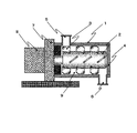
まず、図1中の投入口5より、磁性キャリアコア及び樹脂組成物からなる被処理物を投入する。ケーシング1の内周部と回転体2の間の空間9に対する、投入される処理物の空間充填率としては50%以上、98%以下である場合に、磁性キャリアコア表面への樹脂組成物の被覆処理が均一且つ迅速に行うことができる。より好ましくは70%以上、98%以下である。ここで空間充填率とは、[投入される被処理物の仕込み量(質量)]/[(ケーシング1の内周部と回転体2の間の空間9の体積)×(被処理物のゆるみ見掛け密度)]×100で表される。空間充填率が50%以上である場合には、回転体2表面に設けられた攪拌羽根3と処理物との衝突に加えて、被処理物同士の衝突が十分に行えるとともに、ケーシング1の内周部と攪拌羽根3の微小間隙における被覆処理が効率よく行える。又、空間充填率が従来の機械的衝撃力による乾式コート法よりも高くできるので、タクトアップも可能となる。空間充填率が50%未満である場合には、被処理物同士の衝突が不十分となり、余剰の樹脂組成物が遊離した状態となってしまうため、均一なコートを行うことは困難となってしまう。又、磁性キャリアコア表面へのコート層の密着性に関しても不十分となってしまう。空間充填率が98体積%を超える場合には、空間9における充填率が大きすぎることで、被処理物の移動経路が短くなり、被処理物同士の衝突が不十分となり、均一なコートを行うことは困難となってしまう。
The coating processing step of the present invention is performed using a coating processing apparatus having means for coating processing by mechanical impact force. For example, a coating processing apparatus having the following structure can be used.
First, an object to be processed consisting of a magnetic carrier core and a resin composition is introduced from the
又、被処理物の投入の仕方としては、磁性キャリアコアと被覆用の樹脂組成物は別々に投入してもよく、投入前にミキサーやミルで混合した状態にしてもよい。本発明の磁性キャリアの被覆処理方法である乾式コート法においては、空間充填率が50%以上、98%以下であるので、投入された被処理物同士の衝突が十分であることから、被処理物を別々に投入しても良好な処理が可能であることが利点である。 In addition, as a method of charging the object to be processed, the magnetic carrier core and the coating resin composition may be charged separately, or may be mixed with a mixer or a mill before charging. In the dry coating method, which is a coating treatment method of the magnetic carrier of the present invention, the space filling rate is 50% or more and 98% or less. It is an advantage that good treatment is possible even if the materials are charged separately.
次に、投入された被処理物は、回転体2表面に設けられた攪拌羽根3により攪拌・混合されながら、ケーシング1の内周部と攪拌羽根3との微小間隙において被覆処理された後、排出口6から排出される。尚、図1においては、回転体2は、下方に位置する攪拌羽根が紙面の前面を通って上方へと移動する方向に回転する。この際、図2−1に示す回転体2表面の攪拌羽根3aは、回転体2の軸方向の一方向(投入口5側→排出口6側)に被処理物を送るための送り攪拌機構として働き、攪拌羽根3bは、回転体2の軸方向の一方向とは逆方向(排出口6→投入口5)に被処理物を送るための戻し攪拌機構として働く。これらの機構により、被処理物は送りと戻しが繰り返され、ケーシング1内での被処理物の移動経路が複雑且つ長くなる。この送りと戻しにより、攪拌羽根3と被処理物の衝突、また被処理物同士の衝突をより十分に生じさせ、ケーシング1の内周部と攪拌羽根3の微小間隙における被覆処理をより効率よく行うことができる。その結果、磁性キャリアコア表面への樹脂組成物の被覆を均一且つ迅速に行うことができるようになった。
Next, the charged object to be processed is coated and processed in a minute gap between the inner peripheral portion of the
又、回転体2表面に設けられた攪拌羽根3の位置関係としては、以下の例のように配置されていることが好ましい。例えば攪拌羽根3bは、投入口5側の端部位置が、投入口5側の隣接する他の攪拌羽根3aの排出口6側の端部位置と、軸方向の位置において、重なっていることが好ましい。つまり、図2−1において、攪拌羽根3aの端部位置から垂直方向に線を引くと、攪拌羽根3aと3aに隣接する攪拌羽根3bとが幅dだけ重なる位置関係にあることが好ましい。他の攪拌羽根においても位置関係は同様である。攪拌羽根3aと攪拌羽根3bがこの位置関係にあると、処理物が攪拌羽根3aの端部から攪拌羽根3bの端部へと移動しやすくなり、回転体2の回転に伴い、処理物の送りと戻しをより効果的に行うことができる。なお、上記の攪拌羽根3aと攪拌羽根3bとが重なる幅dの長さは、羽根の回転体の軸方向の長さの50%以下であることが好ましい。
The positional relationship of the stirring blades 3 provided on the surface of the
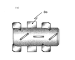
又、本発明に用いられる被覆処理装置の攪拌部材の形状としては、例えば図2に示したようなものを用いることができる。図2−1に示されるように、攪拌羽根3aもしくは3bといった、送り・戻しの攪拌羽根の他に、図2−2及び図2−3に示されるように回転体の軸方向と同方向に配置された攪拌羽根3cがあっても良い。また、攪拌部材の形状としては、図2−4に示されるように、パドル形状のものであってもよい。攪拌部材の形状・設置・角度に関しては、磁性キャリアコア及び樹脂組成物などの処理物の粒径、真比重、流動性で適宜調整可能である。
Moreover, as a shape of the stirring member of the coating processing apparatus used for this invention, what was shown, for example in FIG. 2 can be used. As shown in FIG. 2-1, in addition to the agitating / returning agitating blade such as the agitating
攪拌部材の周速としては、攪拌部材の最外端部で5m/sec以上、50m/sec以下であることが、磁性キャリアコア表面への樹脂組成物の被覆が均一且つ迅速に行えるという点で好ましい。より好ましくは10m/sec以上、20m/sec以下である。
攪拌部材の周速が上記の範囲内であれば、磁性キャリアコアに被覆されない樹脂組成物が残ってしまうこともなく、また、磁性キャリアコアの割れや欠けを発生させることもなく、安定して良好な被覆処理を行うことができる。
The peripheral speed of the stirring member is 5 m / sec or more and 50 m / sec or less at the outermost end portion of the stirring member in that the resin composition can be uniformly and rapidly coated on the surface of the magnetic carrier core. preferable. More preferably, it is 10 m / sec or more and 20 m / sec or less.
If the peripheral speed of the stirring member is within the above range, the resin composition that is not coated on the magnetic carrier core does not remain, and the magnetic carrier core is not cracked or chipped. Good coating treatment can be performed.
又、本発明に用いられる被覆処理装置の、ケーシングと攪拌部材との間隙としては0.5mm以上、30.0mm以下であることが、磁性キャリアコア表面への樹脂組成物の被覆が均一且つ迅速に行えるという点で好ましい。より好ましくは、1.0mm以上、10.0mm以下である。ケーシングと攪拌部材の間隙が上記の範囲内であれば、周速が前記範囲にある場合と同じく、安定して良好な処理を行うことができる。また、上記被覆処理装置を用いた上記被処理物の処理時間は、2分以上、60分以下であることが、好ましい。 In the coating processing apparatus used in the present invention, the gap between the casing and the stirring member is 0.5 mm or more and 30.0 mm or less, so that the surface of the magnetic carrier core can be uniformly and quickly coated. It is preferable in that it can be performed. More preferably, it is 1.0 mm or more and 10.0 mm or less. As long as the gap between the casing and the stirring member is within the above range, as in the case where the peripheral speed is within the above range, stable and satisfactory treatment can be performed. Moreover, it is preferable that the processing time of the said to-be-processed object using the said coating processing apparatus is 2 minutes or more and 60 minutes or less.
本発明における磁性キャリアの加熱処理工程は、上記の被覆処理工程に続いて、下記式(1)及び(2)を満たす条件により加熱処理することを特徴としている。
Tg(℃)≦Th(℃)≦Tg+50(℃)・・・(1)
1000(℃・min)≦Th×M(℃・min)≦30000(℃・min)・・・(2)
(Th:加熱処理工程における加熱処理温度、Tg:樹脂組成物に含まれる樹脂成分のガラス転移温度、M:加熱処理工程における加熱処理時間)
The heat treatment step of the magnetic carrier in the present invention is characterized in that the heat treatment is performed under the conditions satisfying the following formulas (1) and (2) following the above-described coating treatment step.
Tg (° C.) ≦ Th (° C.) ≦ Tg + 50 (° C.) (1)
1000 (° C./min)≦Th×M (° C./min)≦30000 (° C./min) (2)
(Th: Heat treatment temperature in the heat treatment step, Tg: Glass transition temperature of the resin component contained in the resin composition, M: Heat treatment time in the heat treatment step)
上記の被覆処理工程に続いて上記式(1)及び(2)を満たす加熱処理を行うことによって、理由は定かではないが、磁性キャリアにおけるコート層と磁性キャリアコアの密着性が向上し、長期に渡って良好な画像が得られる磁性キャリアを得ることができることを見出した。 Although the reason is not clear by performing the heat treatment satisfying the above formulas (1) and (2) following the coating treatment step, the adhesion between the coat layer and the magnetic carrier core in the magnetic carrier is improved, and long-term It has been found that a magnetic carrier capable of obtaining a good image can be obtained.
加熱処理工程における加熱処理温度Th(℃)が、式(1)の範囲にあることで、被覆処理後のコート層中の樹脂成分が半溶融状態となり、コート層と磁性キャリアコア表面のわずかな間隙が生じるのを防いだり、被覆処理された磁性キャリアコアと樹脂組成物間の接着面の歪みを緩和することができるものと考えられる。このことにより、磁性キャリアコアとの密着性の高いコート層を形成することができる。より好ましくは、Th(℃)がTg(℃)以上、Tg+30(℃)以下である。また、本発明における被覆処理工程が上記の方法であることで、加熱処理工程において加熱処理温度が樹脂成分のガラス転移温度よりも高くなったとしても、被覆処理時に余剰となった樹脂組成物が磁性キャリアの合一を促進することもない。加熱処理温度Th(℃)が樹脂組成物中に含有される樹脂成分のガラス転移温度Tg(℃)より低い場合は、被覆処理工程後の磁性キャリアにおけるコート層中の樹脂成分が半溶融状態になっていないものと考えられ、長期における磁性キャリアの表面の耐磨耗性の向上が望めない。又、加熱処理温度Th(℃)が樹脂組成物中に含有される樹脂成分のガラス転移温度Tg+50(℃)より高い場合は、被覆処理工程後の磁性キャリアにおけるコート層中の樹脂成分が溶融状態となってしまうものと考えられ、
加熱処理工程において磁性キャリアの合一が促進されてしまう。
When the heat treatment temperature Th (° C.) in the heat treatment step is in the range of the formula (1), the resin component in the coating layer after the coating treatment is in a semi-molten state, and the coating layer and the surface of the magnetic carrier core are slightly It is considered that the formation of a gap can be prevented, and the distortion of the adhesive surface between the coated magnetic carrier core and the resin composition can be reduced. This makes it possible to form a coat layer with high adhesion to the magnetic carrier core. More preferably, Th (° C.) is Tg (° C.) or more and Tg + 30 (° C.) or less. Moreover, even if the heat treatment temperature is higher than the glass transition temperature of the resin component in the heat treatment step because the coating treatment step in the present invention is the above method, the surplus resin composition at the time of the coating treatment is obtained. It does not promote the union of magnetic carriers. When the heat treatment temperature Th (° C.) is lower than the glass transition temperature Tg (° C.) of the resin component contained in the resin composition, the resin component in the coat layer in the magnetic carrier after the coating treatment step is in a semi-molten state. It is considered that the wear resistance of the surface of the magnetic carrier in the long term cannot be improved. When the heat treatment temperature Th (° C.) is higher than the glass transition temperature Tg + 50 (° C.) of the resin component contained in the resin composition, the resin component in the coat layer in the magnetic carrier after the coating treatment step is in a molten state. It is thought that will become,
The union of magnetic carriers is promoted in the heat treatment process.
更に、加熱処理工程における加熱処理温度Th(℃)と加熱処理工程における加熱処理時間M(min)の関係が、式(2)の範囲にあることで、磁性キャリアに適正な熱エネルギーを与えることができると考えられ、磁性キャリアコアとの密着性のより高いコート層を形成することができる。より好ましくは、Th×M(℃・min)が3000(℃・min)以上、15000(℃・min)以下である。Th×M(℃・min)が1000より小さい場合は、密着性の更なる向上は望めない。Th×M(℃・min)が30000より大きい場合は、与える熱エネルギーが大きすぎるためか、磁性キャリアの合一が発生してしまう場合がある。 Furthermore, when the relationship between the heat treatment temperature Th (° C.) in the heat treatment step and the heat treatment time M (min) in the heat treatment step is in the range of the formula (2), appropriate heat energy is given to the magnetic carrier. Therefore, it is possible to form a coat layer having higher adhesion to the magnetic carrier core. More preferably, Th × M (° C./min) is 3000 (° C./min) or more and 15000 (° C./min) or less. When Th × M (° C./min) is smaller than 1000, further improvement in adhesion cannot be expected. If Th × M (° C. · min) is greater than 30000, the thermal energy applied may be too large, or the magnetic carriers may be merged.
本発明における加熱処理工程に用いることのできる加熱処理装置としては、金属製や耐熱ガラスの容器に被覆処理物を入れて真空乾燥機で処理するようなバット式処理装置、被覆処理物を回転容器に入れて行うロータリー式加熱処理装置、攪拌翼及び加熱処理手段を備えたバッチ式混合機及び連続式ミルいずれの装置も使用可能である。本発明においては、磁性キャリアの合一を抑制し、均一に加熱処理ができるという点でロータリー式加熱処理装置を好ましく用いる。 As a heat treatment apparatus that can be used in the heat treatment step in the present invention, a bat-type treatment apparatus in which a coating treatment product is put in a metal or heat-resistant glass container and processed by a vacuum dryer, and the coating treatment article is a rotating container. Any of a rotary type heat treatment apparatus, a batch mixer equipped with a stirring blade and heat treatment means, and a continuous mill can be used. In the present invention, a rotary heat treatment apparatus is preferably used from the viewpoint that the coalescence of the magnetic carriers is suppressed and the heat treatment can be performed uniformly.
又、本発明における被覆処理工程は、被服処理装置中の回転体に備えられた流路及び/又はケーシングに備えられた流路に流体が導入されることで温度制御がされ、前記被覆処理工程における被覆処理温度Tc(℃)と、加熱処理工程における加熱処理温度Th(℃)が、下記式(3)を満たすことが好ましい。
Tc(℃)≦Th(℃)・・・(3)
従って本発明における被覆処理工程で用いる被覆処理装置は、被覆処理装置中の回転体及びケーシングに温度制御のための流路を備えていることが好ましい。例えば、図1の4で示されるように、ケーシング1中にジャケット4が存在し、そのジャケットを流路とすることが挙げられる。また、回転体中及び回転体軸を空洞とし、その空洞を流路とすることができる。
本発明における被覆処理工程においては、被覆処理温度Tcを樹脂成分のガラス転移温度Tgより低くしても均一な被覆処理が可能である。この理由としては、本発明における被覆処理装置に投入する被処理物の空間充填率の調整と被覆処理装置中の送り/戻しの機構により、ケーシングや攪拌部材と投入された被処理物との衝突に加えて、被処理物同士の衝突が効果的に生じることによる衝突熱で、Tcが局所的にTg以上となっていることが考えられる。そのため、Tcをより低い温度に設定して被覆処理を施し、ThをTc以上として加熱処理を行うことで、磁性キャリアコアとのより密着性の高いコート層を形成することができる。ThがTcより低い場合には、被覆処理後の磁性キャリアにおけるコート層中の樹脂成分が半溶融状態になっていないものと考えられ、長期における磁性キャリアの表面の耐磨耗性の向上が望めない。
Further, in the coating process in the present invention, the temperature is controlled by introducing a fluid into the channel provided in the rotating body and / or the channel provided in the casing in the clothing processing apparatus, and the coating process It is preferable that the coating treatment temperature Tc (° C.) in and the heat treatment temperature Th (° C.) in the heat treatment step satisfy the following formula (3).
Tc (° C.) ≦ Th (° C.) (3)
Therefore, it is preferable that the coating processing apparatus used in the coating processing step of the present invention is provided with a flow path for temperature control in the rotating body and the casing in the coating processing apparatus. For example, as shown by 4 in FIG. 1, a jacket 4 exists in the
In the coating treatment step of the present invention, uniform coating treatment is possible even when the coating treatment temperature Tc is lower than the glass transition temperature Tg of the resin component. The reason for this is that the casing and the stirring member collide with the input processing object by adjusting the space filling rate of the processing object to be input to the coating processing apparatus and the feed / return mechanism in the coating processing apparatus in the present invention. In addition, it is conceivable that Tc is locally greater than or equal to Tg due to the heat of collision caused by the effective collision between objects to be processed. Therefore, a coating layer having higher adhesion with the magnetic carrier core can be formed by performing a coating process with Tc set at a lower temperature and performing a heat treatment with Th set to Tc or higher. When Th is lower than Tc, it is considered that the resin component in the coat layer of the magnetic carrier after the coating treatment is not in a semi-molten state, and it is possible to improve the wear resistance of the surface of the magnetic carrier over a long period of time. Absent.
又、本発明における加熱処理工程の加熱処理は、酸素濃度が10.0体積%以下で行われることが好ましい。これは、磁性キャリアコアに用いる磁性体が、高温で酸素濃度が高い場合には、酸化されてしまうことがあるからである。磁性キャリアコアの酸化が進むと、調製された磁性キャリアの比抵抗が上がってしまい、良好な現像性が得られなくなる傾向がある。又、酸素濃度を10.0体積%以下にする手段としては、真空ポンプでの減圧処理及び窒素ガス等の不活性ガスのフローによって行う。本発明においては、窒素ガスのフローにより、酸素濃度を10.0体積%以下に抑制した条件で加熱処理を行うことで、磁性キャリアとしてトナーへの帯電付与性が向上し、磁性キャリアコアとコート層の密着性が高まるので、好ましく用いられる。 Moreover, it is preferable that the heat processing of the heat processing process in this invention are performed by oxygen concentration 10.0 volume% or less. This is because the magnetic material used for the magnetic carrier core may be oxidized when the oxygen concentration is high at high temperatures. As the oxidation of the magnetic carrier core proceeds, the specific resistance of the prepared magnetic carrier increases, and there is a tendency that good developability cannot be obtained. Further, as means for reducing the oxygen concentration to 10.0% by volume or less, it is performed by a decompression process using a vacuum pump and a flow of an inert gas such as nitrogen gas. In the present invention, by performing a heat treatment under a condition in which the oxygen concentration is suppressed to 10.0% by volume or less by the flow of nitrogen gas, the charge imparting property to the toner as a magnetic carrier is improved, and the magnetic carrier core and the coating are coated. Since the adhesiveness of a layer improves, it is used preferably.
又、本発明の磁性キャリアの製造方法においては、磁性キャリアコアを被覆する樹脂組
成物が、少なくとも樹脂成分と個数平均粒径(D1)が0.01μm以上、3.00μm以下の微粒子とを有していることが好ましい。これは、樹脂組成物の樹脂成分が磁性キャリアコア表面に被覆される際に、上記微粒子が磁性キャリアコア間に介在しスペーサー効果を発揮するためである。これにより、磁性キャリアの合一の発生を更に抑制し、コート均一性を更に向上することができる。又、加熱処理工程においても、上記微粒子が磁性キャリアコア間に介在しスペーサー効果を発揮するので、コート均一性が高く、耐磨耗性の高い磁性キャリアを得ることができる。上記微粒子としては、架橋性の樹脂粒子や金属酸化物、カーボンブラック等が好ましく使用され、形状としては球状のものが好ましく用いられる。又、上記微粒子の個数平均粒径が0.01μmより小さい場合は、スペーサー効果が得られず、更なるコート均一性の向上は望めない。一方、上記微粒子の個数平均粒径が3.00μmを超える場合は、スペーサー効果は得られるものの、微粒子の分散が不均一となってしまうために、トナーへの帯電付与にバラつきが生じる場合がある。
In the method for producing a magnetic carrier of the present invention, the resin composition covering the magnetic carrier core has at least a resin component and fine particles having a number average particle diameter (D1) of 0.01 μm or more and 3.00 μm or less. It is preferable. This is because when the resin component of the resin composition is coated on the surface of the magnetic carrier core, the fine particles are interposed between the magnetic carrier cores to exert a spacer effect. Thereby, generation | occurrence | production of the unification | combination of a magnetic carrier can further be suppressed, and coat uniformity can further be improved. Also in the heat treatment step, since the fine particles are interposed between the magnetic carrier cores and exhibit a spacer effect, a magnetic carrier with high coat uniformity and high wear resistance can be obtained. As the fine particles, crosslinkable resin particles, metal oxides, carbon black and the like are preferably used, and spherical shapes are preferably used. On the other hand, when the number average particle diameter of the fine particles is smaller than 0.01 μm, the spacer effect cannot be obtained, and further improvement in coat uniformity cannot be expected. On the other hand, when the number average particle diameter of the fine particles exceeds 3.00 μm, the spacer effect can be obtained, but the dispersion of the fine particles becomes non-uniform, and thus there may be variations in the charge imparted to the toner. .
本発明の製造方法により得られる磁性キャリアは、体積基準の50%粒径(D50)が15μm以上、100μm以下であり、真比重が2.5g/cm3以上、5.2g/cm3以下であることが好ましい。
本発明により得られる磁性キャリアは、D50が15μm以上、100μm以下であることで、磁性キャリア製造時の磁性キャリアコアと樹脂組成物の混合性も良好となり、コート均一性が向上する。又、得られた磁性キャリアを二成分現像剤として用いた際、現像極での磁気ブラシの密度が最適化されるとともに、トナーの帯電量分布をシャープにすることができるので、高画質化を図ることができる。
D50が100μmを超える場合は、製造時の被覆処理工程において磁性キャリアコアと樹脂組成物の混合性が不十分となり、偏在した樹脂組成物に起因して磁性キャリア間の合一が促進される傾向にある。又、得られた磁性キャリアを二成分現像剤として用いた際、現像極での磁気ブラシの密度が疎となって、画質が低下してしまう傾向にある。
D50が15μm未満の場合は、製造時の被覆処理工程において磁性キャリアコアと樹脂組成物の衝突力が不十分となってしまい、偏在した樹脂組成物に起因して磁性キャリア間の合一が促進される傾向にある。又、得られた磁性キャリアを二成分現像剤として用いた際、現像極での磁気ブラシの磁気拘束力が小さくなってしまい、感光体上への磁性キャリア付着が生じてしまう傾向にある。より好ましくは、D50が20μm以上、80μm以下である。
なお、本発明の製造方法により得られる磁性キャリアは、磁性キャリアコアの粒径及びコート量を調整することにより、体積基準の50%粒径(D50)を上記範囲に調整することができる。
The magnetic carrier obtained by the production method of the present invention has a volume-based 50% particle size (D50) of 15 μm or more and 100 μm or less, and a true specific gravity of 2.5 g / cm 3 or more and 5.2 g / cm 3 or less. Preferably there is.
When the magnetic carrier obtained by the present invention has a D50 of 15 μm or more and 100 μm or less, the mixing property of the magnetic carrier core and the resin composition during the production of the magnetic carrier is improved, and the coat uniformity is improved. In addition, when the obtained magnetic carrier is used as a two-component developer, the density of the magnetic brush at the development pole is optimized and the toner charge amount distribution can be sharpened. Can be planned.
When D50 exceeds 100 μm, the mixing property between the magnetic carrier core and the resin composition becomes insufficient in the coating treatment process at the time of manufacture, and the coalescence between the magnetic carriers tends to be promoted due to the unevenly distributed resin composition. It is in. Further, when the obtained magnetic carrier is used as a two-component developer, the density of the magnetic brush at the developing pole is sparse and the image quality tends to be lowered.
When D50 is less than 15 μm, the collision force between the magnetic carrier core and the resin composition becomes insufficient in the coating process during manufacturing, and the unification between the magnetic carriers is promoted due to the unevenly distributed resin composition. Tend to be. Further, when the obtained magnetic carrier is used as a two-component developer, the magnetic binding force of the magnetic brush at the developing pole is reduced, and the magnetic carrier tends to adhere to the photoreceptor. More preferably, D50 is 20 μm or more and 80 μm or less.
In the magnetic carrier obtained by the production method of the present invention, the volume-based 50% particle size (D50) can be adjusted to the above range by adjusting the particle size and the coating amount of the magnetic carrier core.
また、本発明により得られる磁性キャリアは、真比重を2.5g/cm3以上、5.2g/cm3以下とした場合、製造時の被覆処理工程において磁性キャリアコアと樹脂組成物の混合性と衝突力が良好となり、コート均一性がより向上する。又、得られた磁性キャリアを二成分現像剤として用いた場合、トナーと磁性キャリアとの真比重の差が良好となり、トナーへの帯電付与をより良好にすることができる。より好ましくは、2.5g/cm3以上、4.2g/cm3以下である。即ち、上記範囲に真比重を調整した場合には、現像器内でのトナーと磁性キャリアとの攪拌が最適化されるので、トナーの帯電が迅速に行われるようになる。また、トナーの劣化を抑制することができ、更に補給用現像剤用のキャリアとして用いた場合、補強用現像剤が補給されても、長期にわたって良好な画像を得ることができる。なお、本発明の製造方法により得られる磁性キャリアは、磁性キャリアコアの真比重及びコート量を調整することにより、真比重の値を上記範囲に調整することができる。 Further, the magnetic carrier obtained by the present invention has a mixing property of the magnetic carrier core and the resin composition in the coating treatment process at the time of manufacture when the true specific gravity is 2.5 g / cm 3 or more and 5.2 g / cm 3 or less. The impact force is improved and the coat uniformity is further improved. In addition, when the obtained magnetic carrier is used as a two-component developer, the difference in true specific gravity between the toner and the magnetic carrier becomes good, and charging to the toner can be made better. More preferably, it is 2.5 g / cm 3 or more and 4.2 g / cm 3 or less. That is, when the true specific gravity is adjusted within the above range, the toner and the magnetic carrier in the developing device are optimized to be charged, so that the toner is quickly charged. Further, toner deterioration can be suppressed, and when used as a carrier for a replenishing developer, a good image can be obtained over a long period of time even if the reinforcing developer is replenished. In the magnetic carrier obtained by the production method of the present invention, the value of the true specific gravity can be adjusted within the above range by adjusting the true specific gravity and the coating amount of the magnetic carrier core.
また、本発明の製造方法により得られる磁性キャリアは、電界強度5000V/cmにおける比抵抗値が、1.0×106Ω・cm以上、1.0×1015Ω・cm以下である
ことが好ましい。比抵抗値が1.0×10⁶Ω・cmより低くなると、磁性キャリアからの電荷がリークする可能性が高まり、磁性キャリアから静電潜像担持体表面の静電潜像に電荷が注入し、トナー層が形成されず画像が抜けてしまう、所謂リーク画像が発生してしまう傾向がある。比抵抗値が1.0×10¹⁵Ω・cmを超える場合は、現像性が低下し、エッジ強調された画像となってしまう、所謂白抜け画像が発生してしまう傾向がある。本発明の製造方法を用いる場合、樹脂組成物の磁性キャリアコアへの均一なコート性と磁性キャリアの合一が発生しにくいということから、磁性キャリアコアの抵抗値を上記範囲とすることで、十分な現像性が得られ、高い画像濃度が得られる。なお、本発明の製造方法により得られる磁性キャリアは、コート量の調整及び微粒子の抵抗を調整することにより、比抵抗値を上記範囲に調整することができる。
In addition, the magnetic carrier obtained by the production method of the present invention has a specific resistance value of 1.0 × 10 6 Ω · cm or more and 1.0 × 10 15 Ω · cm or less at an electric field strength of 5000 V / cm. preferable. If the specific resistance value is lower than 1.0 × 10 6 Ω · cm, the possibility of leakage of charges from the magnetic carrier increases, and charges are injected from the magnetic carrier into the electrostatic latent image on the surface of the electrostatic latent image carrier. Therefore, there is a tendency that a so-called leak image is generated in which a toner layer is not formed and an image is lost. When the specific resistance value exceeds 1.0 × 10 15 Ω · cm, the developability is lowered, and a so-called white-out image tends to be generated, which results in an edge-enhanced image. When the production method of the present invention is used, since the uniform coating property of the resin composition on the magnetic carrier core and the union of the magnetic carrier are less likely to occur, the resistance value of the magnetic carrier core is in the above range, Sufficient developability is obtained, and a high image density is obtained. In addition, the specific resistance value of the magnetic carrier obtained by the production method of the present invention can be adjusted to the above range by adjusting the coating amount and the resistance of the fine particles.
本発明に用いられる磁性キャリアコアとしては、公知のフェライト粒子、マグネタイト粒子、磁性体分散型樹脂キャリアコア等の磁性キャリアコアが使用でき、例えば以下に記載するように製造される。 As the magnetic carrier core used in the present invention, known magnetic carrier cores such as ferrite particles, magnetite particles, and magnetic material-dispersed resin carrier cores can be used. For example, the magnetic carrier core is manufactured as described below.
磁性キャリアコアは、磁性体を用いて製造される。磁性体としては、鉄、リチウム、ベリリウム、マグネシウム、カルシウム、ルビジウム、ストロンチウム、ニッケル、銅、亜鉛、コバルト、マンガン、クロム及びチタンから選ばれる一種または二種以上の元素を含む磁性フェライト粒子、又はマグネタイト粒子が挙げられる。好ましくは、マグネタイト粒子、又は、銅、亜鉛、マンガン、カルシウム、リチウム及びマグネシウムから選ばれる一種または二種以上の元素を少なくとも有する磁性フェライト粒子である。
具体的なフェライト用磁性体としては以下のものが挙げられる。Ca−Mg−Fe系フェライト、Li−Fe系フェライト、Ca−Li−Fe系フェライト、Mn−Mg−Fe系フェライト、Mn−Mg−Sr−Fe系フェライト、及びLi−Mg−Fe系フェライトの如き鉄系酸化物のフェライト磁性体。
The magnetic carrier core is manufactured using a magnetic material. Magnetic materials include magnetic ferrite particles containing one or more elements selected from iron, lithium, beryllium, magnesium, calcium, rubidium, strontium, nickel, copper, zinc, cobalt, manganese, chromium and titanium, or magnetite Particles. Preferably, it is a magnetite particle or a magnetic ferrite particle having at least one element selected from copper, zinc, manganese, calcium, lithium and magnesium.
Specific examples of the magnetic material for ferrite include the following. Such as Ca—Mg—Fe ferrite, Li—Fe ferrite, Ca—Li—Fe ferrite, Mn—Mg—Fe ferrite, Mn—Mg—Sr—Fe ferrite, and Li—Mg—Fe ferrite. Ferrite magnetic body of iron oxide.
鉄系酸化物のフェライトは、それぞれ金属の酸化物、炭酸塩、硝酸塩を湿式あるいは乾式にて混合し、所望のフェライト組成となるよう仮焼成することにより得られる。次いで、得られた鉄系酸化物のフェライトを、サブミクロンまで粉砕する。粉砕されたフェライトに、粒径を調整するための水を20〜50質量%加え、結着樹脂として例えばポリビニルアルコール(分子量500〜10,000)を0.1〜10質量%加えて、スラリーを調製する。このスラリーを、スプレードライヤーを用いて造粒を行い、焼成することでフェライトコアを得ることができる。 Ferrites of iron-based oxides can be obtained by mixing metal oxides, carbonates and nitrates in a wet or dry manner and pre-firing to obtain a desired ferrite composition. Next, the obtained iron-based oxide ferrite is pulverized to submicron. To the pulverized ferrite, 20 to 50% by mass of water for adjusting the particle size is added, and 0.1 to 10% by mass of polyvinyl alcohol (molecular weight of 500 to 10,000) is added as a binder resin. Prepare. The slurry is granulated using a spray dryer and fired to obtain a ferrite core.
又、磁性キャリアの真比重を調整するために、ポーラス状のフェライトコアを得る場合には、造粒時に、空孔密度をコントロールするための炭酸ナトリウムや炭酸カルシウム、及び各種の有機物の如き空孔調整剤を添加してスラリーを形成し、スプレードライヤーを用いて造粒を行い、焼成することで得ることができる。また、フェライト化反応中の粒子成長を阻害させるような材料を添加することにより、フェライト内部に複雑な空隙を形成することもできる。このような材料としては、酸化タンタル、酸化ジルコニウム等が挙げられる。 In addition, in order to adjust the true specific gravity of the magnetic carrier, when obtaining a porous ferrite core, the pores such as sodium carbonate and calcium carbonate and various organic substances are used for controlling the pore density during granulation. It can be obtained by adding a modifier to form a slurry, granulating using a spray dryer, and baking. Further, by adding a material that inhibits the particle growth during the ferritization reaction, a complicated void can be formed inside the ferrite. Examples of such materials include tantalum oxide and zirconium oxide.
また、磁性体分散型樹脂キャリアコアを製造するには、例えばビニル系または非ビニル系の熱可塑性樹脂、および磁性体ならびにその他の添加剤を、混合機により十分に混合する。得られた混合物を、加熱ロール、ニーダー、エクストルーダーの如き混練機を用いて溶融・混練する。冷却された溶融・混練物を粉砕して、さらに分級することにより、磁性体分散型樹脂キャリアコアを得ることができる。得られた磁性体分散型樹脂キャリアコアは、さらに熱又は機械的に球形化してもよい。さらに他の方法としては、磁性体分散型樹脂キャリアコアの結着樹脂を形成するためのモノマーを磁性体存在下で重合して得ることもできる。ここで結着樹脂を形成するためのモノマーとしては以下のものが挙げられる。
ビニル系モノマー、エポキシ樹脂を形成するためのビスフェノール類とエピクロルヒドリン;フェノール樹脂を生成するためのフェノール類とアルデヒド類;尿素樹脂を形成するための尿素とアルデヒド類、メラミンとアルデヒド類。
In order to produce a magnetic material-dispersed resin carrier core, for example, a vinyl-based or non-vinyl-based thermoplastic resin, a magnetic material, and other additives are sufficiently mixed by a mixer. The obtained mixture is melted and kneaded using a kneader such as a heating roll, a kneader, or an extruder. A magnetic material-dispersed resin carrier core can be obtained by pulverizing and classifying the cooled melt-kneaded product. The obtained magnetic material-dispersed resin carrier core may be further spheroidized thermally or mechanically. As another method, a monomer for forming the binder resin of the magnetic material-dispersed resin carrier core can be obtained by polymerizing in the presence of the magnetic material. Examples of the monomer for forming the binder resin include the following.
Bisphenols and epichlorohydrin to form vinyl monomers, epoxy resins; phenols and aldehydes to form phenolic resins; urea and aldehydes to form urea resins, melamine and aldehydes.
フェノール類とアルデヒド類からフェノール樹脂を合成する方法が特に好ましく、この場合は、水性媒体に磁性体およびフェノール類とアルデヒド類を添加し、水性媒体中のフェノール類とアルデヒド類を塩基性触媒の存在下で重合させることにより、磁性体分散型樹脂キャリアコアを製造することができる。 A method of synthesizing a phenol resin from phenols and aldehydes is particularly preferable. In this case, a magnetic substance, phenols and aldehydes are added to an aqueous medium, and the phenols and aldehydes in the aqueous medium are present in the presence of a basic catalyst. By polymerizing under the above, a magnetic material-dispersed resin carrier core can be produced.
フェノール樹脂を生成するためのフェノール類は、フェノール(ヒドロキシベンゼン)のほか、フェノール性水酸基を有する化合物であればよい。フェノール性水酸基を有する化合物としては、m−クレゾール、p−tert−ブチルフェノール、o−プロピルフェノール、レゾルシノール、ビスフェノールAの如きアルキルフェノール類;芳香環(例えばベンゼン環)の水素またはアルキル基の水素の一部または全部が、塩素原子や臭素原子で置換されたハロゲン化フェノール類が挙げられる。 The phenols for producing the phenol resin may be compounds having a phenolic hydroxyl group in addition to phenol (hydroxybenzene). Examples of the compound having a phenolic hydroxyl group include alkylphenols such as m-cresol, p-tert-butylphenol, o-propylphenol, resorcinol, and bisphenol A; hydrogen of an aromatic ring (for example, benzene ring) or part of hydrogen of an alkyl group Or, halogenated phenols, all of which are substituted with chlorine atoms or bromine atoms.
フェノール樹脂を生成するためのアルデヒド類としては以下のものが挙げられる。例えばホルマリン、パラホルムアルデヒドのいずれかの形態のホルムアルデヒド、およびフルフラールであり、より好ましくはホルムアルデヒドである。 Examples of aldehydes for producing a phenol resin include the following. For example, formalin, formaldehyde in any form of paraformaldehyde, and furfural, more preferably formaldehyde.
アルデヒド類のフェノール類に対するモル比は1乃至4であることが好ましく、1.2乃至3であることがより好ましい。アルデヒド類のフェノール類に対するモル比が1より小さいと、粒子が生成しにくかったり、生成したとしても樹脂の硬化が進行しにくいために、生成する粒子の強度が弱くなったりする傾向がある。一方、アルデヒド類のフェノール類に対するモル比が4よりも大きいと、反応後に水系媒体中に残留する未反応のアルデヒド類が増加し、造粒性が低下する場合がある。フェノール類とアルデヒド類との縮合は、塩基性触媒を用いて行うことができる。該塩基性触媒は通常のレゾール型樹脂の製造に使用されている触媒であればよく、該塩基性触媒の例にはアンモニア水、ヘキサメチレンテトラミン及びジメチルアミン、ジエチルトリアミン、ポリエチレンイミンの如きアルキルアミンが含まれる。これら塩基性触媒のフェノール類に対するモル比は0.02〜0.3であることが好ましい。 The molar ratio of aldehydes to phenols is preferably 1 to 4, and more preferably 1.2 to 3. If the molar ratio of aldehydes to phenols is less than 1, particles are difficult to produce, and even if they are produced, the resin does not easily cure, and the strength of the particles produced tends to be weak. On the other hand, when the molar ratio of aldehydes to phenols is larger than 4, unreacted aldehydes remaining in the aqueous medium after the reaction may increase, and the granulation property may decrease. The condensation of phenols with aldehydes can be performed using a basic catalyst. The basic catalyst may be any catalyst used in the production of ordinary resol type resins. Examples of the basic catalyst include aqueous ammonia, hexamethylenetetramine, dimethylamine, diethyltriamine, and alkylamines such as polyethyleneimine. Is included. The molar ratio of these basic catalysts to phenols is preferably 0.02 to 0.3.
次に本発明に用いられる、磁性キャリアコア表面を被覆する樹脂組成物に関して説明する。
本発明に用いられる樹脂組成物は少なくとも樹脂成分を含有する。樹脂成分としては、熱可塑性樹脂が好ましく用いられる。また、樹脂成分としては、一種類の樹脂であってもよく、二種以上の樹脂の組み合わせでもよい。樹脂成分としての熱可塑性樹脂の例には、ポリスチレン;ポリメチルメタクリレートやスチレン−アクリル酸共重合体等のアクリル樹脂;スチレン−ブタジエン共重合体;エチレン−酢酸ビニル共重合体;ポリ塩化ビニル;ポリ酢酸ビニル;ポリフッ化ビニリデン樹脂;フルオロカーボン樹脂;パーフルオロカーボン樹脂;溶剤可溶性パーフルオロカーボン樹脂;ポリビニルアルコール;ポリビニルアセタール;ポリビニルピロリドン;石油樹脂;セルロース;酢酸セルロース、硝酸セルロース、メチルセルロース、ヒドロキシメチルセルロース、ヒドロキシメチルセルロース、ヒドロキシプロピルセルロース等のセルロース誘導体;ノボラック樹脂;低分子量ポリエチレン;飽和アルキルポリエステル樹脂、ポリエチレンテレフタレート、ポリブチレンテレフタレート、ポリアリレートといったポリエステル樹脂;ポリアミド樹脂;ポリアセタール樹脂;ポリカーボネート樹脂;ポリエーテルスルホン樹脂;ポリスルホン樹脂;ポリフェニレンサルファイド樹脂;ポリエーテルケトン樹脂が含まれる。
Next, the resin composition for coating the magnetic carrier core surface used in the present invention will be described.
The resin composition used in the present invention contains at least a resin component. As the resin component, a thermoplastic resin is preferably used. Moreover, as a resin component, one type of resin may be sufficient and the combination of 2 or more types of resin may be sufficient. Examples of the thermoplastic resin as the resin component include polystyrene; acrylic resins such as polymethyl methacrylate and styrene-acrylic acid copolymer; styrene-butadiene copolymer; ethylene-vinyl acetate copolymer; polyvinyl chloride; Polyvinyl acetate; polyvinylidene fluoride resin; fluorocarbon resin; perfluorocarbon resin; solvent-soluble perfluorocarbon resin; polyvinyl alcohol; polyvinyl acetal; polyvinyl pyrrolidone; petroleum resin; cellulose; Cellulose derivatives such as propyl cellulose; novolak resin; low molecular weight polyethylene; saturated alkyl polyester resin, polyethylene terephthalate, Polybutylene terephthalate, such as polyarylate polyester resin; include polyether ketone resin; polyamide resin; polyacetal resin; polycarbonate resins; polyether sulfone resins; polysulfone resin; polyphenylene sulfide resin.
樹脂組成物に含まれる樹脂成分のテトラヒドロフラン(THF)可溶分の重量平均分子
量Mwは、15,000〜1,000,000であることが、磁性キャリアコアとの密着性や、被覆する際に特に均一に磁性キャリアコア表面を被覆することができるという点で好ましい。
When the weight average molecular weight Mw of the tetrahydrofuran (THF) soluble part of the resin component contained in the resin composition is 15,000 to 1,000,000, the adhesion to the magnetic carrier core and the coating are performed. This is particularly preferable in that the surface of the magnetic carrier core can be uniformly coated.
また、樹脂組成物に含まれる樹脂成分の示差走査熱量分析装置により測定されるガラス転移温度(Tg)については、50℃以上150℃以下が、本発明における加熱処理をするのに好ましい。 Moreover, about the glass transition temperature (Tg) measured with the differential scanning calorimetry apparatus of the resin component contained in a resin composition, 50 to 150 degreeC is preferable for performing the heat processing in this invention.
また、樹脂組成物は微粒子を含有していても良い。磁性キャリアコアを被覆する樹脂組成物における微粒子の含有量は、樹脂成分100質量部に対して、微粒子2乃至100質量部の割合で含有されることが好ましい。微粒子の含有量が上記範囲内にある場合には、微粒子の添加効果であるスペーサー効果が十分に発揮され、磁性キャリアコアに良好な樹脂被覆を行うことが可能となる。一方、被覆層の耐久性を損なうこともない。 Moreover, the resin composition may contain fine particles. The content of the fine particles in the resin composition covering the magnetic carrier core is preferably contained in a ratio of 2 to 100 parts by mass of the fine particles with respect to 100 parts by mass of the resin component. When the content of the fine particles is within the above range, the spacer effect that is the effect of adding the fine particles is sufficiently exhibited, and it is possible to perform good resin coating on the magnetic carrier core. On the other hand, the durability of the coating layer is not impaired.
本発明に用いる樹脂組成物に含まれる微粒子としては、有機材料および無機材料のいずれの微粒子であってもよいが、被覆する際に微粒子の形状を保持することができる強度を有している架橋樹脂微粒子、無機微粒子が好ましい。架橋樹脂微粒子を形成する架橋樹脂としては、架橋ポリメチルメタクリレート樹脂、架橋ポリスチレン樹脂、メラミン樹脂、グアナミン樹脂、尿素樹脂、フェノール樹脂及びナイロン樹脂が挙げられる。また、無機微粒子としては、マグネタイト、ヘマタイト、シリカ、アルミナ、チタニアが挙げられる。特に、上記の無機微粒子は、トナーへの帯電付与の促進、チャージアップの低減、及びトナーとの離型性の向上の点で好ましい。又、微粒子の形状としては、被覆処理時のスペーサー効果を得るために、球状のものが好ましく用いられる。 The fine particles contained in the resin composition used in the present invention may be any fine particles of an organic material and an inorganic material, but are crosslinked having a strength capable of maintaining the shape of the fine particles when coated. Resin fine particles and inorganic fine particles are preferred. Examples of the crosslinked resin forming the crosslinked resin fine particles include a crosslinked polymethyl methacrylate resin, a crosslinked polystyrene resin, a melamine resin, a guanamine resin, a urea resin, a phenol resin, and a nylon resin. Examples of the inorganic fine particles include magnetite, hematite, silica, alumina, and titania. In particular, the above-mentioned inorganic fine particles are preferable from the viewpoint of promoting charging imparted to the toner, reducing charge-up, and improving releasability from the toner. As the shape of the fine particles, a spherical shape is preferably used in order to obtain a spacer effect during the coating treatment.
また、本発明に用いる樹脂組成物は、導電性微粒子を含んでいてもよい。導電性微粒子は、体積抵抗が1×10⁸Ω・cm以下であることが好ましく、1×10⁶Ω・cm以下であることがより好ましい。また、平均一次粒径が10nm以上100nm以下であることが好ましい。導電性微粒子は、カーボンブラック微粒子、グラファイト微粒子、酸化亜鉛微粒子、および酸化錫微粒子が挙げられる。特に導電性微粒子としてカーボンブラック微粒子が好ましい。これらの導電性微粒子は、少ない添加量でその良導電性により、磁性キャリアの比抵抗を適宜コントロールすることができる。 Moreover, the resin composition used in the present invention may contain conductive fine particles. The conductive fine particles preferably have a volume resistance of 1 × 10 8 Ω · cm or less, and more preferably 1 × 10 6 Ω · cm or less. Moreover, it is preferable that an average primary particle diameter is 10 nm or more and 100 nm or less. Examples of the conductive fine particles include carbon black fine particles, graphite fine particles, zinc oxide fine particles, and tin oxide fine particles. In particular, carbon black fine particles are preferable as the conductive fine particles. These conductive fine particles can appropriately control the specific resistance of the magnetic carrier due to the good conductivity with a small addition amount.
本発明に用いられる樹脂組成物に含有される樹脂成分の製法の例としては、溶液重合法や乳化重合法、懸濁重合法といったいずれの重合法も適用可能である。樹脂組成物は、樹脂組成物の体積基準の50%粒径(D50)をDb(μm)、電子写真用キャリアコアのD50をDc(μm)としたとき、Db/Dcが0.10以上、50以下を満たす微粒子状にて装置に導入されることが好ましい。この粒径範囲の樹脂組成物は、重合反応時の条件変更や、重合反応後、乾燥させた後に結着樹脂を粉砕することで、得ることができる。又、樹脂組成物に微粒子を添加する場合は、重合反応時に添加しても、粉砕後にミキサーで混合しても良い。 As an example of the method for producing the resin component contained in the resin composition used in the present invention, any polymerization method such as a solution polymerization method, an emulsion polymerization method, and a suspension polymerization method can be applied. The resin composition has a Db / Dc of 0.10 or more, where 50% particle size (D50) of the resin composition is Db (μm) and D50 of the electrophotographic carrier core is Dc (μm). It is preferably introduced into the apparatus in the form of fine particles satisfying 50 or less. A resin composition in this particle size range can be obtained by changing the conditions during the polymerization reaction or by crushing the binder resin after drying after the polymerization reaction. Moreover, when adding microparticles | fine-particles to a resin composition, it may add at the time of a polymerization reaction, and may mix with a mixer after a grinding | pulverization.
又、樹脂成分を溶媒に溶解させた樹脂溶液をスプレードライ法でドライアップして、樹脂組成物として用いることも可能である。スプレードライ法により樹脂組成物を得る際に微粒子を添加する場合は、メディアを用いたビーズミルで樹脂溶液中に微粒子を分散させた後に、スプレードライ法でドライアップしても、ドライアップ後にミキサーで樹脂組成物と微粒子を混合しても良い。更には、樹脂組成物に用いられる樹脂成分が粒径の大きな固形物である場合は、樹脂成分と微粒子とを混合し、樹脂成分と微粒子とを二軸式押出機にて混練し、その後粉砕機にて粉砕することにより樹脂組成物を得る方法も好ましく用いられる。 Moreover, it is also possible to dry up the resin solution which melt | dissolved the resin component in the solvent by the spray-drying method, and to use it as a resin composition. When adding fine particles when obtaining a resin composition by the spray drying method, after the fine particles are dispersed in the resin solution with a bead mill using a medium, the particles may be dried up by the spray drying method. The resin composition and fine particles may be mixed. Furthermore, when the resin component used in the resin composition is a solid having a large particle size, the resin component and the fine particles are mixed, and the resin component and the fine particles are kneaded with a twin screw extruder, and then pulverized. A method of obtaining a resin composition by pulverizing with a machine is also preferably used.
本発明の磁性キャリアと共に用いられるトナーとしては、結着樹脂、着色剤、ワックス等からなる公知のものが使用でき特に限定されない。例えば、粉砕法、重合法、乳化凝集法、溶解懸濁法等のいずれの方法で製造されたものであってもよい。又、結着樹脂の主たる成分としては、ポリエステル樹脂、ビニル系樹脂、又はハイブリッド樹脂を用いることが好ましい。 The toner used with the magnetic carrier of the present invention is not particularly limited, and known toners such as a binder resin, a colorant, and wax can be used. For example, it may be produced by any method such as a pulverization method, a polymerization method, an emulsion aggregation method, and a dissolution suspension method. Further, it is preferable to use a polyester resin, a vinyl resin, or a hybrid resin as the main component of the binder resin.
以下に、本発明に関わる測定方法について詳細に述べる。
<被覆処理装置に投入される磁性キャリアコア及び樹脂組成物の空間充填率の測定方法>
まず、被覆処理装置を構成するケーシングの内周部と回転体との空間へ水を満たし、その水の体積(被覆処理装置中の空間体積)を測定する。次に、パウダーテスタPT−R(ホソカワミクロン社製)を用い、磁性キャリアと樹脂組成物の混合物のゆるみ見掛け密度(g/cm3)の測定を行う。測定環境は、23℃、50%RHで行った。また測定は、混合物を、目開き150μmの篩を用いて、振幅を1mmで振動させながらちょうど100ccとなるまで容積100ccの金属製カップに捕集した。そして、金属製カップに捕集した混合物量から、ゆるみ見掛け密度(g/cm3)を測定する。
ついで、下記に示した算出式により空間充填率(%)を得た。
空間充填率(%)=上記混合物の仕込み量(質量)/(混合物のゆるみ見掛け密度×上記空間の体積)×100
Below, the measuring method concerning this invention is described in detail.
<Method for Measuring Space Filling Ratio of Magnetic Carrier Core and Resin Composition Charged into Coating Treatment Apparatus>
First, water is filled in the space between the inner peripheral portion of the casing constituting the coating processing apparatus and the rotating body, and the volume of the water (space volume in the coating processing apparatus) is measured. Next, the loose apparent density (g / cm 3 ) of the mixture of the magnetic carrier and the resin composition is measured using a powder tester PT-R (manufactured by Hosokawa Micron). The measurement environment was 23 ° C. and 50% RH. For the measurement, the mixture was collected in a metal cup having a capacity of 100 cc using a sieve having an aperture of 150 μm and vibrating at an amplitude of 1 mm until it became exactly 100 cc. Then, the loose apparent density (g / cm 3 ) is measured from the amount of the mixture collected in the metal cup.
Subsequently, the space filling rate (%) was obtained by the calculation formula shown below.
Space filling rate (%) = preparation amount (mass) of the mixture / (sloose apparent density of the mixture × volume of the space) × 100
<被覆用樹脂組成物に含有される樹脂成分のガラス転移点(Tg)測定>
樹脂組成物に含有される樹脂成分のガラス転移点(Tg)は、示差走査熱量分析装置「Q1000」(TA Instruments社製)を用いてASTM D3418−82に準じて測定する。装置検出部の温度補正はインジウムと亜鉛の融点を用い、熱量の補正についてはインジウムの融解熱を用いる。具体的には、樹脂組成物を約10mgを精秤し、アルミニウム製のパンの中に入れ、リファレンスとして空のアルミニウム製のパンを用い、測定範囲30乃至200℃の間で、昇温速度10℃/minで測定を行う。この昇温過程で、温度40℃乃至100℃の範囲において比熱変化が得られる。このときの比熱変化が出る前と出た後のベースラインの中間点の線と示差熱曲線との交点を、樹脂組成物に含有される樹脂成分のガラス転移温度Tgとする。
<Measurement of glass transition point (Tg) of resin component contained in coating resin composition>
The glass transition point (Tg) of the resin component contained in the resin composition is measured according to ASTM D3418-82 using a differential scanning calorimeter “Q1000” (manufactured by TA Instruments). The temperature correction of the device detection unit uses the melting points of indium and zinc, and the correction of heat uses the heat of fusion of indium. Specifically, about 10 mg of the resin composition is precisely weighed and placed in an aluminum pan, and an empty aluminum pan is used as a reference. Measurement is performed at ° C / min. In this temperature rising process, a specific heat change is obtained in the temperature range of 40 ° C to 100 ° C. At this time, the intersection of the intermediate point line of the baseline before and after the specific heat change and the differential heat curve is defined as the glass transition temperature Tg of the resin component contained in the resin composition.
<被覆用樹脂組成物に含有される微粒子の個数平均粒径(D1)測定>
微粒子の粒度分布測定は、樹脂組成物に含有される樹脂成分が可溶な有機溶媒中に溶解し、微粒子が溶液中に分散した状態で行った。測定装置としては、レーザー回折粒度分布計LS−230型(ベックマンコールター製)を用いて少量モジュールを取り付けて測定した。測定の際に用いた光学モデルは、実数部1.5、虚数部0.3とし、溶媒の屈折率は使用した有機溶媒の屈折率を入力した。
<Measurement of number average particle diameter (D1) of fine particles contained in coating resin composition>
The particle size distribution of the fine particles was measured in a state where the resin component contained in the resin composition was dissolved in a soluble organic solvent and the fine particles were dispersed in the solution. As a measuring device, a laser diffraction particle size distribution analyzer LS-230 type (manufactured by Beckman Coulter) was used for measurement with a small amount of module attached. The optical model used in the measurement was a real part 1.5 and an imaginary part 0.3, and the refractive index of the organic solvent used was input as the refractive index of the solvent.
<被覆用樹脂組成物、磁性キャリアコア、及び磁性キャリアの体積基準の50%粒径(D50)測定>
粒度分布測定は、マイクロトラックMT3300EX(日機装社製)にて測定を行った。測定には、乾式測定用のTurbotrac試料供給機を装着して行った。粒径は体積基準の50%粒径(D50)を求めた。
<Measurement of volume-based 50% particle size (D50) of coating resin composition, magnetic carrier core, and magnetic carrier>
The particle size distribution was measured with Microtrac MT3300EX (Nikkiso Co., Ltd.). For the measurement, a Turbotrac sample feeder for dry measurement was attached. As the particle size, a volume-based 50% particle size (D50) was obtained.
<磁性キャリアコア、被覆用樹脂組成物、及び磁性キャリアの真比重測定>
サンプルの準備としては、磁性キャリア、磁性キャリアコア、樹脂組成物はそのまま測定できる。磁性キャリアコア及び樹脂組成物を磁性キャリアから分離する必要がある場合は、分離は以下の方法で行った。先ず、磁性キャリア100質量部を蓋つきのガラス瓶に量り取り、トルエン200質量部を添加し、振とう機(YS−8D型:(株)ヤヨイ製)にて振とうした。振とう機の振幅条件は200rpm、2分間とした。振とう後は、ビンの外側から磁性キャリアコアをマグネットにて捕集しつつ、トルエン溶液を分離した。こ
れを5回繰り返した後、真空乾燥機にて50℃、8時間乾燥させ、常温に冷却し、磁性キャリアコアを得、一方でトルエン溶液より、トルエンを除去することにより樹脂組成物を得て、それらを測定試料とした。
真比重の測定法としては、ヘリウムによるガス置換式の測定法を用いた。測定装置はアキュピック1330(島津製作所社製)を用いた。測定条件は、ステンレス製の内径18.5mm,長さ39.5mm,容量10cm3のセルに、測定サンプルを4g入れる。次いで、試料セル中のサンプルの容積をヘリウムの圧力変化によって測定し、求められた容積とサンプルの質量から真比重を求める。
<Measurement of true specific gravity of magnetic carrier core, coating resin composition, and magnetic carrier>
As sample preparation, the magnetic carrier, magnetic carrier core, and resin composition can be measured as they are. When it was necessary to separate the magnetic carrier core and the resin composition from the magnetic carrier, the separation was performed by the following method. First, 100 parts by mass of a magnetic carrier was weighed into a glass bottle with a lid, 200 parts by mass of toluene was added, and the mixture was shaken with a shaker (YS-8D type: manufactured by Yayoi Co., Ltd.). The amplitude condition of the shaker was 200 rpm for 2 minutes. After shaking, the toluene solution was separated while collecting the magnetic carrier core from the outside of the bottle with a magnet. After repeating this 5 times, it was dried in a vacuum dryer at 50 ° C. for 8 hours, cooled to room temperature to obtain a magnetic carrier core, while obtaining a resin composition by removing toluene from the toluene solution. These were used as measurement samples.
As a method for measuring the true specific gravity, a gas replacement method using helium was used. Accupic 1330 (manufactured by Shimadzu Corporation) was used as the measuring apparatus. Measurement conditions are as follows: 4 g of a measurement sample is put in a stainless steel cell having an inner diameter of 18.5 mm, a length of 39.5 mm, and a capacity of 10 cm 3 . Next, the volume of the sample in the sample cell is measured by changing the pressure of helium, and the true specific gravity is obtained from the obtained volume and the mass of the sample.
<被覆用樹脂組成物に含有される樹脂成分の分子量測定>
樹脂組成物に含有される樹脂成分のテトラヒドロフラン(THF)可溶分の分子量分布は、ゲルパーミエーションクロマトグラフィー(GPC)により、以下のようにして測定する。
まず、室温で24時間かけて、樹脂組成物をテトラヒドロフラン(THF)に溶解する。そして、得られた溶液を、ポア径が0.2μmの耐溶剤性メンブランフィルター「マエショリディスク」(東ソー社製)で濾過してサンプル溶液を得る。尚、サンプル溶液は、THFに可溶な成分の濃度が0.8質量%となるように調整する。このサンプル溶液を用いて、以下の条件で測定する。
装置:HLC8120 GPC(検出器:RI)(東ソー社製)
カラム:Shodex KF−801、802、803、804、805、806、807の7連(昭和電工社製)
溶離液:テトラヒドロフラン(THF)
流速:1.0ml/min
オーブン温度:40.0℃
試料注入量:0.10ml
試料の分子量の算出にあたっては、標準ポリスチレン樹脂(例えば、商品名「TSKスタンダード ポリスチレン F−850、F−450、F−288、F−128、F−80、F−40、F−20、F−10、F−4、F−2、F−1、A−5000、A−2500、A−1000、A−500」、東ソ−社製)を用いて作成した分子量校正曲線を使用する。
<Molecular weight measurement of resin component contained in resin composition for coating>
The molecular weight distribution of the tetrahydrofuran (THF) soluble part of the resin component contained in the resin composition is measured by gel permeation chromatography (GPC) as follows.
First, the resin composition is dissolved in tetrahydrofuran (THF) at room temperature over 24 hours. The obtained solution is filtered through a solvent-resistant membrane filter “Maescho Disc” (manufactured by Tosoh Corporation) having a pore diameter of 0.2 μm to obtain a sample solution. The sample solution is adjusted so that the concentration of the component soluble in THF is 0.8% by mass. Using this sample solution, measurement is performed under the following conditions.
Apparatus: HLC8120 GPC (detector: RI) (manufactured by Tosoh Corporation)
Column: Seven series of Shodex KF-801, 802, 803, 804, 805, 806, 807 (manufactured by Showa Denko KK)
Eluent: Tetrahydrofuran (THF)
Flow rate: 1.0 ml / min
Oven temperature: 40.0 ° C
Sample injection volume: 0.10 ml
In calculating the molecular weight of the sample, standard polystyrene resin (for example, trade name “TSK Standard Polystyrene F-850, F-450, F-288, F-128, F-80, F-40, F-20, F— 10, F-4, F-2, F-1, A-5000, A-2500, A-1000, A-500 ", manufactured by Tosoh Corporation) are used.
<磁性キャリアの比抵抗測定>
磁性キャリアの比抵抗は、図3に概略される測定装置を用いて測定される。抵抗測定セルAは、断面積2.4cm2の穴の開いた円筒状のホルダ15、下部電極(ステンレス製)11、下部電極台座(PTFE樹脂製)14、上部電極(ステンレス製)12から構成される。下部電極台座14上に円筒状のホルダ15を載せ、試料(例えば、キャリア)13を0.7g充填し、充填された試料13に上部電極12を載せ、試料の厚みを測定する。予め試料のないときの厚みをd’(ブランク)、0.7g充填したときの実際の試料の厚みd、試料を充填したときの厚みd’(試料)とすると、試料の厚みは下記式で表せる。
d=d’(試料)−d’(ブランク)
電極間に電圧を印加し、そのときに流れる電流を測定することによってキャリア及びキャリアコアの比抵抗を求めることができる。測定には、エレクトロメーター16(ケスレー6517 ケスレー社製)及び制御用に処理コンピュータ17を用いる。
測定条件は、磁性成分と電極との接触面積S=2.4cm2、上部電極の荷重240gとする。電圧の印加条件は、エレクトロメーターの内部プログラムを利用し、まず最大1000V印加可能かどうか(電流のリミッターを超えない範囲)をエレクトロメーター自身が判断し、印加電圧の最大値を自動的に決める。その最大電圧値を5分割した電圧をステップとして30秒間保持させた後の電流値を測定する。例えば、最大印加電圧が1000Vの場合には、1000V、800V、600V、400V、200Vを印加し、それ
ぞれのステップで30秒保持後の電流値を測定する。それをコンピュータにより処理することで、電界強度、比抵抗を算出して、グラフにプロットする。比抵抗、電界強度は、下記式にて求められる。
比抵抗(Ω・cm)=(印加電圧(V)/測定電流(A))×S(cm2)/d(cm)電界強度(V/cm)=印加電圧(V)/d(cm)
磁性キャリアの5000V/cmにおける比抵抗は、グラフ上5000V/cmにおける比抵抗をグラフから読み取る。グラフ上の5000V/cmの縦線と実測した比抵抗のラインの交点をもって、5000V/cm時の比抵抗値とする。また、交点が存在しない場合には、測定点の外挿を行い、5000V/cmの縦線の交点をもって、5000V/cm時の比抵抗値とする。
<Measurement of resistivity of magnetic carrier>
The specific resistance of the magnetic carrier is measured using a measuring device outlined in FIG. The resistance measuring cell A includes a
d = d ′ (sample) −d ′ (blank)
The specific resistance of the carrier and the carrier core can be obtained by applying a voltage between the electrodes and measuring the current flowing at that time. For the measurement, an electrometer 16 (manufactured by Kesley 6517 manufactured by Kesley) and a
The measurement conditions are a contact area S = 2.4 cm 2 between the magnetic component and the electrode, and a load of 240 g on the upper electrode. The voltage application condition uses an internal program of the electrometer. First, the electrometer itself determines whether a maximum of 1000 V can be applied (a range not exceeding the current limiter), and automatically determines the maximum value of the applied voltage. The voltage value obtained by dividing the maximum voltage value into five steps is used as a step, and the current value after being held for 30 seconds is measured. For example, when the maximum applied voltage is 1000 V, 1000 V, 800 V, 600 V, 400 V, and 200 V are applied, and the current value after holding for 30 seconds is measured in each step. By processing it by a computer, the electric field strength and the specific resistance are calculated and plotted on a graph. The specific resistance and the electric field strength are obtained by the following formula.
Specific resistance (Ω · cm) = (applied voltage (V) / measured current (A)) × S (cm 2 ) / d (cm) electric field strength (V / cm) = applied voltage (V) / d (cm)
The specific resistance at 5000 V / cm of the magnetic carrier is read from the specific resistance at 5000 V / cm on the graph. The intersection of the vertical line of 5000 V / cm on the graph and the measured specific resistance line is taken as the specific resistance value at 5000 V / cm. If there is no intersection point, extrapolation of the measurement point is performed, and the intersection point of the vertical line of 5000 V / cm is set to a specific resistance value at 5000 V / cm.
以下、具体的製造例及び実施例をもって本発明を更に詳しく説明するが、本発明は何らこれらに限定されるものではない。 Hereinafter, the present invention will be described in more detail with reference to specific production examples and examples, but the present invention is not limited thereto.
<磁性キャリアコア製造例1乃至3>
下記に示す材料を用いて磁性キャリアコア(a−1)を作製した。
・フェノール 10質量部
・ホルムアルデヒド溶液(37質量%水溶液) 6質量部
・マグネタイト粒子(個数平均粒径0.3μm) 84質量部
上記材料と、28質量%アンモニア水5質量部、水25質量部をフラスコに入れ、混合しながら30分間で85℃まで昇温・保持し、3時間重合反応させて硬化させた。その後、30℃まで冷却し、更に水を添加した後上澄み液を除去し、沈殿物を水洗した後風乾した。次いで、これを減圧下(5hPa以下)、60℃の温度で乾燥して、マグネタイト粒子がフェノール樹脂中に分散された磁性微粒子分散型の磁性キャリアコア(a−1)を得た。得られた磁性キャリアコア(a−1)の物性を表1に示す。又、水の量をそれぞれ10質量部、90質量部に変えることにより、粒径違いの磁性キャリアコア(a−2)及び(a−3)を得た。得られた磁性キャリアコア(a−2)及び(a−3)の物性を表1に示す。
<Magnetic carrier core production examples 1 to 3>
A magnetic carrier core (a-1) was produced using the materials shown below.
-Phenol 10 parts by mass-Formaldehyde solution (37% by mass aqueous solution) 6 parts by mass-Magnetite particles (number average particle size 0.3 μm) 84 parts by mass The above materials, 5 parts by mass of 28% by mass ammonia water, and 25 parts by mass water The mixture was placed in a flask, heated and maintained at 85 ° C. for 30 minutes with mixing, and polymerized for 3 hours to be cured. Then, it cooled to 30 degreeC, after adding water, the supernatant liquid was removed, the precipitate was washed with water, and then air-dried. Subsequently, this was dried under reduced pressure (5 hPa or less) at a temperature of 60 ° C. to obtain a magnetic carrier core (a-1) of a magnetic fine particle dispersed type in which magnetite particles were dispersed in a phenol resin. Table 1 shows the physical properties of the magnetic carrier core (a-1) obtained. Moreover, magnetic carrier cores (a-2) and (a-3) having different particle diameters were obtained by changing the amounts of water to 10 parts by mass and 90 parts by mass, respectively. Table 1 shows the physical properties of the magnetic carrier cores (a-2) and (a-3) thus obtained.
<磁性キャリアコア製造例4>
下記の材料を用いて、フェライトキャリアコアを作製した。
Fe2O3 66.5質量部
MnCO3 28.1質量部
Mg(OH)2 4.8質量部
SrCO3 0.6質量部
となるようにフェライト組成物を湿式混合した後、900℃で2時間仮焼し、仮焼されたフェライト組成物をボールミルで粉砕した。得られた粉砕物の個数平均粒径は0.4μmであった。
得られた粉砕物に、水(粉砕物に対して300質量部)と重量平均分子量5,000のポリビニルアルコール(粉砕物に対して3質量部)を加え、スプレードライヤーにより造粒した。電気炉にて、酸素濃度1.0%の窒素雰囲気下、造粒物を1300℃で6時間焼結した後に粉砕し、さらに分級することによりMn−Mg−Sr−Feフェライト組成の磁性キャリアコア(a−4)を得た。得られた磁性キャリアコア(a−4)の物性を表1に示す。
<Magnetic carrier core production example 4>
A ferrite carrier core was produced using the following materials.
Fe 2 O 3 66.5 parts by mass MnCO 3 28.1 parts by mass Mg (OH) 2 4.8 parts by mass SrCO 3 0.6 parts by mass After wet mixing the ferrite composition at 900 ° C. 2 The time-calcined and calcined ferrite composition was pulverized with a ball mill. The number average particle size of the obtained pulverized product was 0.4 μm.
Water (300 parts by mass with respect to the pulverized product) and polyvinyl alcohol having a weight average molecular weight of 5,000 (3 parts by mass with respect to the pulverized product) were added to the obtained pulverized product, and granulated with a spray dryer. In an electric furnace, the granulated product is sintered at 1300 ° C. for 6 hours in a nitrogen atmosphere with an oxygen concentration of 1.0%, and then pulverized and further classified to form a magnetic carrier core having a Mn—Mg—Sr—Fe ferrite composition (A-4) was obtained. Table 1 shows the physical properties of the magnetic carrier core (a-4) obtained.
<磁性キャリアコア製造例5>
下記の材料を用いて、フェライトキャリアコアを作製した。
Fe2O3 66.5質量部
MnCO3 28.1質量部
Mg(OH)2 4.8質量部
SrCO3 0.6質量部
となるようにフェライト組成物を湿式混合した後、900℃で2時間仮焼し、仮焼されたフェライト組成物をボールミルで粉砕した。得られた粉砕物の平均粒径は0.4μmであった。
得られた粉砕物に、水(粉砕物に対して300質量部)と重量平均分子量5,000のポリビニルアルコール(粉砕物に対して2質量部)、空孔形成剤として炭酸ナトリウム(個数平均粒径2μm)を5質量部加え、スプレードライヤーにより造粒した。電気炉にて、酸素濃度1.0%の窒素雰囲気下、1150℃で4時間焼成し、更に酸素を含まない窒素雰囲気下で、750℃、30分間焼結した後に粉砕し、さらに分級することによりポーラス状のMn−Mg−Sr−Feフェライト組成の磁性キャリアコア(a−5)を得た。得られた磁性キャリアコア(a−5)の物性を表1に示す。
<Magnetic carrier core production example 5>
A ferrite carrier core was produced using the following materials.
Fe 2 O 3 66.5 parts by mass MnCO 3 28.1 parts by mass Mg (OH) 2 4.8 parts by mass SrCO 3 0.6 parts by mass After wet mixing the ferrite composition at 900 ° C. 2 The time-calcined and calcined ferrite composition was pulverized with a ball mill. The average particle size of the obtained pulverized product was 0.4 μm.
To the obtained pulverized product, water (300 parts by mass with respect to the pulverized product), polyvinyl alcohol having a weight average molecular weight of 5,000 (2 parts by mass with respect to the pulverized product), and sodium carbonate (number average particles as a pore-forming agent). 5 parts by mass (
<磁性キャリアコア製造例6>
下記に示す材料を用いて磁性キャリアコア(a−6)を作製した。
・ポリメチルメタクリレート樹脂(重量平均分子量80000) 30質量部
・マグネタイト粒子(個数平均粒径0.3μm) 70質量部
上記材料をヘンシェルミキサー等で混合した後、二軸式押出機にて溶融混練した。得られた混練物を冷却し、ハンマーミルにて1mm以下に粗粉砕し、更に機械式粉砕機を用いて微粉砕した。次に、微粉砕物を風力式分級機により分級した後、ハイブリタイゼーションシステム(奈良機械社製)を用いて表面改質処理を行うことにより磁性キャリアコア(a−6)を得た。得られた磁性キャリアコア(a−6)の物性を表1に示す。
<Magnetic carrier core production example 6>
A magnetic carrier core (a-6) was produced using the materials shown below.
・ Polymethylmethacrylate resin (weight average molecular weight 80000) 30 parts by mass ・ Magnetite particles (number average particle size 0.3 μm) 70 parts by mass After the above materials were mixed with a Henschel mixer or the like, they were melt-kneaded with a twin screw extruder. . The obtained kneaded material was cooled, coarsely pulverized to 1 mm or less with a hammer mill, and further finely pulverized using a mechanical pulverizer. Next, after classifying the finely pulverized product with a wind classifier, a magnetic carrier core (a-6) was obtained by performing surface modification using a hybridization system (manufactured by Nara Machinery Co., Ltd.). Table 1 shows the physical properties of the magnetic carrier core (a-6) obtained.
<磁性キャリアコア製造例7>
マグネタイト粒子(個数平均粒径0.3μm)と水(マグネタイト粒子100質量部に対して300質量部)と重量平均分子量5,000のポリビニルアルコール(粉砕物に対して3質量部)を加え、スプレードライヤーにより造粒した。電気炉にて、酸素濃度1.0%の窒素雰囲気下、造粒物を1300℃で6時間焼結した後に粉砕し、さらに分級することによりマグネタイト組成の磁性キャリアコア(a−7)を得た。得られた磁性キャリアコア(a−7)の物性を表1に示す。
<Magnetic carrier core production example 7>
Add magnetite particles (number average particle size 0.3 μm), water (300 parts by mass with respect to 100 parts by mass of magnetite particles) and polyvinyl alcohol having a weight average molecular weight of 5,000 (3 parts by mass with respect to the pulverized product), and spray. Granulated with a dryer. In an electric furnace, the granulated product is sintered at 1300 ° C. for 6 hours in a nitrogen atmosphere with an oxygen concentration of 1.0%, pulverized, and further classified to obtain a magnetic carrier core (a-7) having a magnetite composition. It was. Table 1 shows the physical properties of the magnetic carrier core (a-7) obtained.

<樹脂組成物の製造例1>
メタクリル酸メチルモノマー100質量部を、還流冷却器、温度計、窒素吸い込み管、及びすり合わせ方式撹拌装置を有する四つ口フラスコに加えた。さらにトルエン90質量
部、メチルエチルケトン110質量部、及びアゾビスイソバレロニトリル2.0質量部を加えた。得られた混合物を、窒素気流下70℃で10時間保持し、MMA重合体溶液を得た。この溶液から溶剤を除去し、得られた固形物をハンマーミルにて粗粉砕し、更に機械式粉砕機を用いて微粉砕を行うことにより樹脂成分を得た。得られた樹脂成分100質量部に対して、平均一次粒径が20nm、体積抵抗値が9.8×10⁻²Ω・cmのカーボンブラック(c−1)を10質量部加えて、ヘンシェルミキサーを用いて2分間攪拌・混合を行い、樹脂成分と導電剤の混合物であるである樹脂組成物(b−1)を得た。得られた樹脂組成物(b−1)の物性を表2に示す。
<Production Example 1 of Resin Composition>
100 parts by weight of methyl methacrylate monomer was added to a four-necked flask having a reflux condenser, a thermometer, a nitrogen suction tube, and a friction stirrer. Further, 90 parts by mass of toluene, 110 parts by mass of methyl ethyl ketone, and 2.0 parts by mass of azobisisovaleronitrile were added. The obtained mixture was kept at 70 ° C. for 10 hours under a nitrogen stream to obtain an MMA polymer solution. The solvent was removed from the solution, and the resulting solid was roughly pulverized with a hammer mill, and further pulverized with a mechanical pulverizer to obtain a resin component. 10 parts by mass of carbon black (c-1) having an average primary particle size of 20 nm and a volume resistance of 9.8 × 10 −2 Ω · cm is added to 100 parts by mass of the obtained resin component, and a Henschel mixer is added. The mixture was stirred and mixed for 2 minutes to obtain a resin composition (b-1) which is a mixture of a resin component and a conductive agent. Table 2 shows the physical properties of the obtained resin composition (b-1).
<樹脂組成物の製造例2>
樹脂組成物の製造例1において、カーボンブラック(c−1)の添加量を20質量部に変更し、更に個数平均粒径0.3μmの架橋ポリメチルメタクリレート微粒子(d−1)を30質量部添加した以外は、樹脂組成物の製造例1と同様にして樹脂組成物(b−2)を得た。得られた樹脂組成物(b−2)の物性を表2に示す。
<Production Example 2 of Resin Composition>
In Production Example 1 of the resin composition, the amount of carbon black (c-1) added was changed to 20 parts by mass, and the crosslinked polymethyl methacrylate fine particles (d-1) having a number average particle size of 0.3 μm were further 30 parts by mass. Except for the addition, a resin composition (b-2) was obtained in the same manner as in Production Example 1 of the resin composition. Table 2 shows the physical properties of the obtained resin composition (b-2).
<トナー製造例>
ポリオキシプロピレン(2.2)−2,2−ビス(4−ヒドロキシフェニル)プロパン30質量部、ポリオキシエチレン(2.2)−2,2−ビス(4−ヒドロキシフェニル)プロパン20質量部、テレフタル酸20質量部、無水トリメリット酸3質量部、フマル酸27質量部及び酸化ジブチル錫をガラス製4リットルの四つ口フラスコに入れ、温度計、撹拌棒、コンデンサー及び窒素導入管を四つ口フラスコに取りつけ、この四つ口フラスコをマントルヒーター内に設置した。窒素雰囲気下210℃で3時間反応を進め、ポリエステル樹脂を得た。得られたポリエステル樹脂のピーク分子量Mpは6500、ガラス転移温度Tgは65℃であった。
次に下記に示す材料及び製法を用いて評価用トナーを作製した。
・上記ポリエステル樹脂 100質量部
・C.I.ピグメントブルー15:3 5質量部
・パラフィンワックス(融点75℃) 5質量部
・3,5−ジ−t−ブチルサリチル酸アルミニウム化合物 0.5質量部
上記の材料をヘンシェルミキサー(FM−75型、三井三池化工機(株)製)で混合した後、二軸式押出機(PCM−30型、池貝製作所製)にて溶融混練した。得られた混練物を冷却し、ハンマーミルにて1mm以下に粗粉砕し、トナー粗砕物を得た。得られたトナー粗砕物を、機械式粉砕機を用いて微粉砕した後、風力分級機により分級し、トナー分級品を得た。得られたトナー分級品100質量部に対して、BET比表面積100m2/gのアナターゼ型の酸化チタンを1.0質量部、BET比表面積130m2/gの疎水性シリカ1.0質量部を添加し、ヘンシェルミキサー(FM−75型、三井三池化工機(株)製)で混合して、評価用トナーを得た。得られたトナーの重量平均粒径(D4)は6.4μmであった。
<Example of toner production>
30 parts by mass of polyoxypropylene (2.2) -2,2-bis (4-hydroxyphenyl) propane, 20 parts by mass of polyoxyethylene (2.2) -2,2-bis (4-hydroxyphenyl) propane, Put 20 parts by mass of terephthalic acid, 3 parts by mass of trimellitic anhydride, 27 parts by mass of fumaric acid and dibutyltin oxide into a 4 liter glass four-necked flask, and add four thermometers, stirring rods, condensers and nitrogen inlet tubes. The flask was attached to a neck flask, and this four-neck flask was placed in a mantle heater. The reaction was allowed to proceed for 3 hours at 210 ° C. in a nitrogen atmosphere to obtain a polyester resin. The obtained polyester resin had a peak molecular weight Mp of 6500 and a glass transition temperature Tg of 65 ° C.
Next, a toner for evaluation was produced using the following materials and production method.
-100 mass parts of said polyester resin-C.I. I. Pigment Blue 15: 3 5 parts by mass, paraffin wax (melting point 75 ° C.) 5 parts by mass, 3,5-di-t-butylsalicylic acid aluminum compound 0.5 part by mass Henshell mixer (FM-75 type, Mitsui) After mixing with Miike Chemical Industries, Ltd., the mixture was melt-kneaded with a twin-screw extruder (PCM-30, manufactured by Ikegai Seisakusho). The obtained kneaded product was cooled and coarsely pulverized to 1 mm or less with a hammer mill to obtain a coarsely pulverized toner. The resulting coarsely pulverized toner was finely pulverized using a mechanical pulverizer and then classified by an air classifier to obtain a toner classified product. To 100 parts by mass of the obtained toner classified product, 1.0 part by mass of anatase-type titanium oxide having a BET specific surface area of 100 m 2 / g and 1.0 part by mass of hydrophobic silica having a BET specific surface area of 130 m 2 / g were added. The toner was added and mixed with a Henschel mixer (FM-75 type, manufactured by Mitsui Miike Chemical Co., Ltd.) to obtain a toner for evaluation. The obtained toner had a weight average particle diameter (D4) of 6.4 μm.
<実施例1>
下記に示した材料及び製法を用いて磁性キャリアを作製した。
・磁性キャリアコア(a−1) 100質量部
・樹脂組成物(b−1) 4質量部
上記材料を図1に示した被覆処理装置を用いて磁性キャリアコア表面への樹脂組成物の被覆を行った。被覆処理条件としては、充填率を95体積%、攪拌羽根の最外端部周速を12m/sec、攪拌羽根とケーシングの間隙を3.0mm、処理時間を20分間とした。尚、温度制御のためのケーシング内の流路(ジャケット)には15℃の冷却水を導入した。被覆処理時の温度は80℃であった。
次に得られた被覆処理物を加熱処理した。加熱処理条件としては、被覆処理物をステンレス製の容器に入れ、真空乾燥機(装置i:DP63、ヤマト科学)にて処理温度100
℃、処理時間120min、酸素濃度0.1体積%とした。コート条件、加熱処理条件を表3、得られた磁性キャリアの物性を表4、現像性の評価結果を表5に示す。尚、得られた磁性キャリアの物性評価及び現像性評価の基準を以下に示す。
<Example 1>
Magnetic carriers were prepared using the materials and manufacturing methods shown below.
Magnetic carrier core (a-1) 100 parts by mass Resin composition (b-1) 4 parts by mass The resin composition is coated on the surface of the magnetic carrier core using the coating apparatus shown in FIG. went. As coating treatment conditions, the filling rate was 95% by volume, the outer peripheral edge peripheral speed of the stirring blade was 12 m / sec, the gap between the stirring blade and the casing was 3.0 mm, and the processing time was 20 minutes. In addition, 15 degreeC cooling water was introduce | transduced into the flow path (jacket) in the casing for temperature control. The temperature during the coating process was 80 ° C.
Next, the obtained coating treatment was heat-treated. As the heat treatment conditions, the coated product is put in a stainless steel container and treated at a treatment temperature of 100 with a vacuum dryer (apparatus i: DP63, Yamato Science).
The treatment temperature was 120 ° C., the oxygen concentration was 0.1 volume%. Table 3 shows coating conditions and heat treatment conditions, Table 4 shows physical properties of the obtained magnetic carrier, and Table 5 shows evaluation results of developability. In addition, the reference | standard of physical property evaluation of the obtained magnetic carrier and developability evaluation is shown below.
<評価項目>
[磁性キャリアの合一度合いの評価]
得られた磁性キャリアを電子顕微鏡(SEM)で観察を行った。一視野に磁性キャリアが100個程度入るように、倍率としては250倍程度で観察した。この観察を10回行い、以下の基準で判断した。
A:合一磁性キャリアが3個未満。
B:合一磁性キャリアが3個以上、6個未満。
C:合一磁性キャリアが6個以上、10個未満。
D:合一磁性キャリアが10個以上、15個未満
E:合一磁性キャリアが15個以上。
<Evaluation items>
[Evaluation of unity degree of magnetic carriers]
The obtained magnetic carrier was observed with an electron microscope (SEM). The magnification was observed at about 250 times so that about 100 magnetic carriers could be included in one field of view. This observation was performed 10 times and judged according to the following criteria.
A: Less than 3 united magnetic carriers.
B: 3 or more and less than 6 united magnetic carriers.
C: The number of united magnetic carriers is 6 or more and less than 10.
D: 10 or more and less than 15 united magnetic carriers E: 15 or more united magnetic carriers
[実効コート量]
得られた磁性キャリア10gを蓋つきのガラス瓶に量り取り、トルエン20gを添加し、振とう機(YS−8D型:(株)ヤヨイ)にて振とうした。振とう機の振幅条件は200rpm、2分間とした。振とう後は、ビンの外側から磁性キャリアをマグネットにて捕集しつつ、トルエンを除去した。これを5回繰り返した後、真空乾燥機にて50℃、8時間乾燥させ、常温に冷却した後、残りの質量M2を測定し、(10−M2)/(磁性キャリアコアに対する樹脂組成物の割合[%]/100)×100=実効コート量(%)とした。尚、実効コート量が100%に近いほど、被覆処理が良好に行われているものと判断した。又、100%にならない理由としては、被覆処理しきれない樹脂組成物の偏在や合一粒子の偏在によるもの、装置への融着や付着によるものと考えられる。実効コート量の評価としては、以下の基準で判断した。尚、評価B以上を実用可能レベルとした。
A:仕込み量に対する実効コート量が90%以上。
B:仕込み量に対する実効コート量が80%以上、90%未満。
C:仕込み量に対する実効コート量が70%以上、80%未満。
D:仕込み量に対する実効コート量が60%以上、70%未満。
E:仕込み量に対する実効コート量が60%未満。
[Effective coat amount]
10 g of the obtained magnetic carrier was weighed into a glass bottle with a lid, 20 g of toluene was added, and the mixture was shaken with a shaker (YS-8D type: Yayoi Co., Ltd.). The amplitude condition of the shaker was 200 rpm for 2 minutes. After shaking, toluene was removed while collecting the magnetic carrier from the outside of the bottle with a magnet. After repeating this 5 times, it was dried at 50 ° C. for 8 hours in a vacuum dryer, cooled to room temperature, then the remaining mass M2 was measured, and (10−M2) / (of the resin composition relative to the magnetic carrier core) Ratio [%] / 100) × 100 = effective coating amount (%). In addition, it was judged that the coating process was performed favorably, so that the effective coating amount was close to 100%. Further, the reason why it does not become 100% is considered to be due to uneven distribution of the resin composition that cannot be covered or due to uneven distribution of coalesced particles, or due to fusion or adhesion to the apparatus. The evaluation of the effective coat amount was judged according to the following criteria. Note that the evaluation B or higher was regarded as a practical level.
A: The effective coat amount with respect to the charged amount is 90% or more.
B: The effective coat amount with respect to the charged amount is 80% or more and less than 90%.
C: The effective coat amount with respect to the charged amount is 70% or more and less than 80%.
D: The effective coat amount with respect to the charged amount is 60% or more and less than 70%.
E: The effective coat amount with respect to the charged amount is less than 60%.
[画像濃度の維持性]
まず、得られた磁性キャリア90質量部と前記評価用トナー10質量部をV型混合機にて混合し二成分現像剤とした。得られた二成分現像剤をキヤノン製フルカラー複写機IRC3220Nを用いて、通常の画像濃度が得られるかどうか評価した。評価は、高温高湿下H/H(30℃、80RH)にて、感光体上のトナーの載り量が0.6g/cm2となるように現像バイアスを調整し、画像を出力した。画像濃度は、ベタ画像を出力し、濃度計X−Rite500型により濃度測定を行い、6点の平均値をとって画像濃度とした。
この初期の画像濃度を100%とし、続いて35℃、90RHの環境下、印字比率10
%の画像にて5万枚(50k)耐久し、50k耐久後のH/H画像濃度の維持率を算出して以下の基準で判断した。尚、評価C以上が実用可能レベルとした。
A:50k耐久後の画像濃度の維持率が90%以上。
B:50k耐久後の画像濃度の維持率が80%以上、90%未満。
C:50k耐久後の画像濃度の維持率が70%以上、80%未満。
D:50k耐久後の画像濃度の維持率が60%以上、70%未満。
E:50k耐久後の画像濃度の維持率が60%未満。
[Image density maintenance]
First, 90 parts by mass of the obtained magnetic carrier and 10 parts by mass of the toner for evaluation were mixed with a V-type mixer to obtain a two-component developer. The obtained two-component developer was evaluated using a Canon full-color copier IRC3220N to determine whether a normal image density could be obtained. The evaluation was performed by adjusting the developing bias so that the applied amount of toner on the photoconductor was 0.6 g / cm 2 at high temperature and high humidity (H / H (30 ° C., 80 RH)) and outputting an image. For the image density, a solid image was output, density measurement was performed with a densitometer X-Rite500 type, and an average value of 6 points was taken as the image density.
The initial image density is set to 100%, and then the printing ratio is 10 in an environment of 35 ° C. and 90 RH.
Durability of 50,000 sheets (50k) with% image was calculated, and the maintenance ratio of H / H image density after 50k durability was calculated and judged according to the following criteria. In addition, the evaluation C or higher was regarded as a practical level.
A: Image density maintenance rate after 50k durability is 90% or more.
B: Image density maintenance rate after 50k durability is 80% or more and less than 90%.
C: Image density maintenance rate after 50k durability is 70% or more and less than 80%.
D: Image density maintenance rate after 50k durability is 60% or more and less than 70%.
E: Image density maintenance rate after 50k durability is less than 60%.
[感光体上Q/M(mC/kg)の維持性]
上記画像濃度の維持性評価の際、感光体上のトナーの載り量が0.6g/cm2となった時点で、感光体上のトナーを、金属円筒管と円筒フィルターにより吸引捕集した。その際金属円筒管を通じてコンデンサーに蓄えられた電荷量Q及び捕集されたトナー質量Mとを測定し、それより単位質量当たりの電荷量Q/M(mC/kg)を計算し、感光体上Q/M(mC/kg)とした。
この初期の感光体上Q/Mを100%とし、続いて35℃、90RHの環境下、印字比率10%の画像にて5万枚(50k)耐久し、50k耐久後の感光体上Q/Mの維持率を算出して以下の基準で判断した。尚、評価C以上が実用可能レベルとした。
A:50k耐久後の感光体上Q/Mの維持率が90%以上。
B:50k耐久後の感光体上Q/Mの維持率が80%以上、90%未満。
C:50k耐久後の感光体上Q/Mの維持率が70%以上、80%未満。
D:50k耐久後の感光体上Q/Mの維持率が60%以上、70%未満。
E:50k耐久後の感光体上Q/Mの維持率が60%未満。
[Maintenance of Q / M (mC / kg) on the photoreceptor]
When the toner density on the photoconductor reached 0.6 g / cm 2 during the evaluation of image density maintenance, the toner on the photoconductor was collected by suction with a metal cylindrical tube and a cylindrical filter. At that time, the charge quantity Q stored in the condenser through the metal cylindrical tube and the collected toner mass M are measured, and the charge quantity Q / M (mC / kg) per unit mass is calculated from the measured quantity. Q / M (mC / kg).
The initial Q / M on the photoconductor is assumed to be 100%. Subsequently, the image is subjected to 50,000 sheets (50k) in an image with a printing ratio of 10% in an environment of 35 ° C. and 90RH, and the Q / M on the photoconductor after 50k is used. The maintenance rate of M was calculated and judged according to the following criteria. In addition, the evaluation C or higher was regarded as a practical level.
A: The maintenance ratio of Q / M on the photoreceptor after 50k durability is 90% or more.
B: The maintenance ratio of Q / M on the photoconductor after 50k durability is 80% or more and less than 90%.
C: The maintenance ratio of Q / M on the photoconductor after 50k durability is 70% or more and less than 80%.
D: The maintenance ratio of Q / M on the photoreceptor after 50k durability is 60% or more and less than 70%.
E: The maintenance ratio of Q / M on the photoconductor after 50k durability is less than 60%.
[コート層の耐磨耗性]
初期の磁性キャリアの実効コート量を100%とし、続いて35℃、90RHの環境下、印字比率10%の画像にて5万枚(50k)耐久し、50k耐久後の磁性キャリアの実効コート量の維持率を算出して以下の基準で判断した。尚、評価C以上が実用可能レベルとした。
A:50k耐久後の実効コート量の維持率が90%以上。
B:50k耐久後の実効コート量の維持率が80%以上、90%未満。
C:50k耐久後の実効コート量の維持率が70%以上、80%未満。
D:50k耐久後の実効コート量の維持率が60%以上、70%未満。
E:50k耐久後の実効コート量の維持率が60%未満。
[Abrasion resistance of coat layer]
The initial effective coat amount of the magnetic carrier is assumed to be 100%, followed by 50,000 sheets (50k) with an image of 10% printing ratio in an environment of 35 ° C and 90RH, and the effective coat amount of the magnetic carrier after 50k endurance. The maintenance ratio was calculated based on the following criteria. In addition, the evaluation C or higher was regarded as a practical level.
A: The maintenance ratio of the effective coat amount after 50k durability is 90% or more.
B: The maintenance ratio of the effective coat amount after 50k durability is 80% or more and less than 90%.
C: The maintenance ratio of the effective coat amount after 50k durability is 70% or more and less than 80%.
D: The maintenance ratio of the effective coat amount after 50k durability is 60% or more and less than 70%.
E: Maintenance rate of effective coat amount after 50k durability is less than 60%.
<実施例2>
実施例1において、加熱処理装置を装置(i)からドラムミキサー(UD−LH−00
1型:杉山重工製、装置ii)に変えて、加熱処理時に窒素をフローさせて酸素濃度を8.0体積%にした以外は実施例1と同様にして磁性キャリアを作製し、各評価を行った。得られた磁性キャリアの物性を表4、現像性の評価結果を表5に示す。
<Example 2>
In Example 1, the heat treatment apparatus is changed from the apparatus (i) to the drum mixer (UD-LH-00).
Type 1: Made of Sugiyama Heavy Industries, apparatus ii), a magnetic carrier was prepared in the same manner as in Example 1 except that nitrogen was flowed during the heat treatment to make the oxygen concentration 8.0% by volume. went. Table 4 shows the physical properties of the obtained magnetic carrier, and Table 5 shows the evaluation results of developability.
<実施例3乃至9>
実施例2において、製造条件を表3に示したように変えた以外は、実施例2と同様にして磁性キャリアを作製し、各評価を行った。得られた磁性キャリアの物性を表4、現像性の評価結果を表5に示す。
<Examples 3 to 9>
In Example 2, a magnetic carrier was prepared and evaluated in the same manner as in Example 2 except that the manufacturing conditions were changed as shown in Table 3. Table 4 shows the physical properties of the obtained magnetic carrier, and Table 5 shows the evaluation results of developability.
<実施例10>
実施例1において、加熱処理装置を装置()からハイフレックスグラル(LFS−GS−2J型:深江パウテック製、装置iii)に変えて、加熱処理条件を表3に示したように
変えた以外は実施例1と同様にして磁性キャリアを作製し、各評価を行った。得られた磁性キャリアの物性を表4、現像性の評価結果を表5に示す。
<Example 10>
In Example 1, except that the heat treatment apparatus was changed from the apparatus () to Hiflex glal (LFS-GS-2J type: Fukae Powtech, apparatus iii), and the heat treatment conditions were changed as shown in Table 3. A magnetic carrier was prepared in the same manner as in Example 1, and each evaluation was performed. Table 4 shows the physical properties of the obtained magnetic carrier, and Table 5 shows the evaluation results of developability.
<実施例11>
実施例1において、加熱処理装置を装置(i)からソリッドエアー(ホソカワミクロン
製、装置iv)に変えて、加熱処理条件を表3に示したように変えた以外は実施例1と同様にして磁性キャリアを作製し、各評価を行った。得られた磁性キャリアの物性を表4、現像性の評価結果を表5に示す。
<Example 11>
In Example 1, the magnetic treatment was performed in the same manner as in Example 1 except that the heat treatment apparatus was changed from the apparatus (i) to solid air (manufactured by Hosokawa Micron, apparatus iv), and the heat treatment conditions were changed as shown in Table 3. Carriers were prepared and evaluated. Table 4 shows the physical properties of the obtained magnetic carrier, and Table 5 shows the evaluation results of developability.
<実施例12乃至20>
実施例2において、製造条件を表3に示したように変えた以外は、実施例2と同様にして磁性キャリアを作製し、各評価を行った。得られた磁性キャリアの物性を表4、現像性の評価結果を表5に示す。
<Examples 12 to 20>
In Example 2, a magnetic carrier was prepared and evaluated in the same manner as in Example 2 except that the manufacturing conditions were changed as shown in Table 3. Table 4 shows the physical properties of the obtained magnetic carrier, and Table 5 shows the evaluation results of developability.
<比較例1>
実施例2において、加熱処理を行わなかった以外は、実施例2と同様にして磁性キャリアを作製し、各評価を行った。得られた磁性キャリアの物性を表4、現像性の評価結果を表5に示す。
<Comparative Example 1>
In Example 2, a magnetic carrier was produced in the same manner as in Example 2 except that no heat treatment was performed, and each evaluation was performed. Table 4 shows the physical properties of the obtained magnetic carrier, and Table 5 shows the evaluation results of developability.
<比較例2乃至6>
実施例2において、製造条件を表3に示したように変えた以外は、実施例2と同様にして磁性キャリアを作製し、各評価を行った。得られた磁性キャリアの物性を表4、現像性の評価結果を表5に示す。
<Comparative Examples 2 to 6>
In Example 2, a magnetic carrier was prepared and evaluated in the same manner as in Example 2 except that the manufacturing conditions were changed as shown in Table 3. Table 4 shows the physical properties of the obtained magnetic carrier, and Table 5 shows the evaluation results of developability.
<比較例7>
実施例2において、被覆処理装置を、熱的な乾式コート装置であるハイフレックスグラル(深江パウテック製)に変えた以外は実施例2と同様にして磁性キャリアを作製し、各評価を行った。得られた磁性キャリアの物性を表4、現像性の評価結果を表5に示す。
<Comparative Example 7>
In Example 2, a magnetic carrier was prepared and evaluated in the same manner as in Example 2 except that the coating treatment apparatus was changed to Hiflex glal (manufactured by Fukae Powtech), which is a thermal dry coat apparatus. Table 4 shows the physical properties of the obtained magnetic carrier, and Table 5 shows the evaluation results of developability.
<比較例8>
実施例2において、被覆処理装置を、機械的衝撃力を用いた乾式コート装置であるハイブリタイザー(奈良機械製)に変えた以外は実施例2と同様にして磁性キャリアを作製し、各評価を行った。得られた磁性キャリアの物性を表4、現像性の評価結果を表5に示す。
<Comparative Example 8>
In Example 2, a magnetic carrier was prepared in the same manner as in Example 2 except that the coating treatment apparatus was changed to a hybridizer (manufactured by Nara Machinery), which is a dry coating apparatus using mechanical impact force. went. Table 4 shows the physical properties of the obtained magnetic carrier, and Table 5 shows the evaluation results of developability.
1:ケーシング
2:回転体
3、3a、3b、3c:攪拌羽根
4:ジャケット
5:投入口
6:排出口
7:支持体
8:駆動部
d:攪拌羽根の位置関係を示す間隔
11:下部電極
12:上部電極
13:サンプル
14:下部電極台座
15:ホルダ
16:エレクトロンメーター
17:処理コンピュータ
A:抵抗測定セル
d:サンプル高さ
1: Casing 2:
Claims (6)
前記被覆処理工程は、少なくとも複数の攪拌部材が表面に設置された回転体と、前記攪拌部材と間隙を有して設けられたケーシングとを有する被覆処理装置を用い、前記回転体を回転させ、前記被覆処理装置中に投入された前記磁性キャリアコア及び前記樹脂組成物を混合することで前記磁性キャリアコアの表面に前記樹脂組成物を被覆処理し、
前記被覆処理装置に投入される前記磁性キャリア及び前記樹脂組成物は、前記回転体と前記ケーシングの内周部との間の空間に対する、投入される磁性キャリアコア及び樹脂組成物の空間充填率が、50%以上、98%以下となるように投入量を調整され、
前記被覆処理装置に投入された前記磁性キャリアコアと前記樹脂組成物は、前記複数の攪拌部材の一部の攪拌部材により、前記回転体の軸方向の一方向に送られ、前記複数の攪拌部材の羽根の他の一部の攪拌部材により、前記回転体の軸方向の逆方向に戻され、送りと戻しとを行いながら前記磁性キャリア表面に前記樹脂組成物の被覆処理が行われ、
前記加熱処理工程は、下記式(1)及び(2)を満たす条件により加熱処理することを特徴とする磁性キャリアの製造方法。
Tg(℃)≦Th(℃)≦Tg+50(℃)・・・(1)
1000(℃・min)≦Th×M(℃・min)≦30000(℃・min)・・・(2)
(Th:加熱処理工程における加熱処理温度、Tg:樹脂組成物に含まれる樹脂成分のガラス転移温度、M:加熱処理工程における加熱処理時間) Using a coating processing apparatus having a means for coating by mechanical impact force, a coating processing step for coating the resin composition on the surface of the magnetic carrier core, and a magnetic film coated by using a heating processing apparatus having a heating means A heat treatment step of heat-treating the carrier, and a method for producing a magnetic carrier obtained by coating the surface of the magnetic carrier core with a resin composition,
The coating treatment step uses a coating processing apparatus having a rotating body having at least a plurality of stirring members installed on the surface, and a casing provided with the stirring member and a gap, and rotates the rotating body, The resin composition is coated on the surface of the magnetic carrier core by mixing the magnetic carrier core and the resin composition introduced into the coating processing apparatus,
The magnetic carrier and the resin composition charged into the coating processing apparatus have a space filling rate of the magnetic carrier core and the resin composition to be charged with respect to a space between the rotating body and the inner peripheral portion of the casing. , The input amount is adjusted to be 50% or more and 98% or less,
The magnetic carrier core and the resin composition charged into the coating processing apparatus are sent in one axial direction of the rotating body by a part of the stirring members, and the plurality of stirring members The other stirring member of the blade is returned in the reverse direction of the axial direction of the rotating body, and the coating treatment of the resin composition is performed on the surface of the magnetic carrier while performing feeding and returning,
The said heat processing process heat-processes on the conditions which satisfy | fill following formula (1) and (2), The manufacturing method of the magnetic carrier characterized by the above-mentioned.
Tg (° C.) ≦ Th (° C.) ≦ Tg + 50 (° C.) (1)
1000 (° C./min)≦Th×M (° C./min)≦30000 (° C./min) (2)
(Th: Heat treatment temperature in the heat treatment step, Tg: Glass transition temperature of the resin component contained in the resin composition, M: Heat treatment time in the heat treatment step)
Tc(℃)≦Th(℃)・・・(3) In the covering process, the temperature is controlled by introducing a fluid into the flow path provided in the rotating body and / or the flow path provided in the casing in the clothing processing apparatus. The method for producing a magnetic carrier according to claim 1, wherein the coating temperature Tc (° C.) and the heat treatment temperature Th (° C.) in the heat treatment step satisfy the following formula (3).
Tc (° C.) ≦ Th (° C.) (3)
The magnetic carrier has a volume-based 50% particle size (D50) of 15 μm or more and 100 μm or less, and a true specific gravity of 2.5 g / cm 3 or more and 5.2 g / cm 3 or less. Item 6. The magnetic carrier according to Item 5.
Priority Applications (1)
| Application Number | Priority Date | Filing Date | Title |
|---|---|---|---|
| JP2008173124A JP5197195B2 (en) | 2008-07-02 | 2008-07-02 | Magnetic carrier manufacturing method and magnetic carrier using the manufacturing method |
Applications Claiming Priority (1)
| Application Number | Priority Date | Filing Date | Title |
|---|---|---|---|
| JP2008173124A JP5197195B2 (en) | 2008-07-02 | 2008-07-02 | Magnetic carrier manufacturing method and magnetic carrier using the manufacturing method |
Publications (3)
| Publication Number | Publication Date |
|---|---|
| JP2010014853A true JP2010014853A (en) | 2010-01-21 |
| JP2010014853A5 JP2010014853A5 (en) | 2011-08-18 |
| JP5197195B2 JP5197195B2 (en) | 2013-05-15 |
Family
ID=41701036
Family Applications (1)
| Application Number | Title | Priority Date | Filing Date |
|---|---|---|---|
| JP2008173124A Expired - Fee Related JP5197195B2 (en) | 2008-07-02 | 2008-07-02 | Magnetic carrier manufacturing method and magnetic carrier using the manufacturing method |
Country Status (1)
| Country | Link |
|---|---|
| JP (1) | JP5197195B2 (en) |
Cited By (3)
| Publication number | Priority date | Publication date | Assignee | Title |
|---|---|---|---|---|
| WO2013180212A1 (en) * | 2012-05-31 | 2013-12-05 | 戸田工業株式会社 | Magnetic carriers for electrophotographic developer, processes for producing same, and two-component developer |
| JP2016075953A (en) * | 2016-01-07 | 2016-05-12 | 戸田工業株式会社 | Magnetic carrier for electrophotographic developer, manufacturing method of the same, and two-component developer |
| JP2016170314A (en) * | 2015-03-13 | 2016-09-23 | 富士ゼロックス株式会社 | Method for manufacturing two component development carrier |
Families Citing this family (1)
| Publication number | Priority date | Publication date | Assignee | Title |
|---|---|---|---|---|
| JP2012220883A (en) * | 2011-04-13 | 2012-11-12 | Casio Electronics Co Ltd | Negatively chargeable decoloring electrophotographic toner and method for manufacturing the same |
-
2008
- 2008-07-02 JP JP2008173124A patent/JP5197195B2/en not_active Expired - Fee Related
Cited By (6)
| Publication number | Priority date | Publication date | Assignee | Title |
|---|---|---|---|---|
| WO2013180212A1 (en) * | 2012-05-31 | 2013-12-05 | 戸田工業株式会社 | Magnetic carriers for electrophotographic developer, processes for producing same, and two-component developer |
| JP2013250455A (en) * | 2012-05-31 | 2013-12-12 | Toda Kogyo Corp | Magnetic carrier for electrophotographic developer and production method of the same, and two-component developer |
| CN104350429A (en) * | 2012-05-31 | 2015-02-11 | 户田工业株式会社 | Magnetic carriers for electrophotographic developer, processes for producing same, and two-component developer |
| US9952524B2 (en) | 2012-05-31 | 2018-04-24 | Toda Kogyo Corp. | Magnetic carrier for electrophotographic developer and process for producing the same, and two-component system developer |
| JP2016170314A (en) * | 2015-03-13 | 2016-09-23 | 富士ゼロックス株式会社 | Method for manufacturing two component development carrier |
| JP2016075953A (en) * | 2016-01-07 | 2016-05-12 | 戸田工業株式会社 | Magnetic carrier for electrophotographic developer, manufacturing method of the same, and two-component developer |
Also Published As
| Publication number | Publication date |
|---|---|
| JP5197195B2 (en) | 2013-05-15 |
Similar Documents
| Publication | Publication Date | Title |
|---|---|---|
| JP4739316B2 (en) | Electrophotographic carrier production method and electrophotographic carrier produced using the production method | |
| JP6012328B2 (en) | Manufacturing method of magnetic carrier | |
| KR101396011B1 (en) | Method for producing magnetic carrier | |
| JP6848566B2 (en) | Carrier, developer, replenisher developer, image forming apparatus, image forming method and process cartridge | |
| JP2016020968A (en) | Toner for electrostatic charge image development and manufacturing method of the same, electrostatic charge image developer, toner cartridge, process cartridge, image forming apparatus, and image forming method | |
| JP5197195B2 (en) | Magnetic carrier manufacturing method and magnetic carrier using the manufacturing method | |
| JP6385127B2 (en) | Two-component developer | |
| JP5495633B2 (en) | Magnetic carrier and two-component developer | |
| JP4557168B2 (en) | Magnetic carrier for electrophotographic developer, method for producing the same, and two-component developer | |
| JP2007057743A (en) | Carrier for electrostatic latent image development, developer for electrostatic latent image development and developing device | |
| JP5361558B2 (en) | Magnetic carrier manufacturing method and magnetic carrier manufactured using the manufacturing method | |
| JP5197194B2 (en) | Magnetic carrier manufacturing method and magnetic carrier manufactured by the manufacturing method | |
| JP2011033861A (en) | Magnetic carrier, two-component developer and developer for replenishment | |
| JP4258356B2 (en) | Electrostatic latent image developer carrier and manufacturing method thereof, electrostatic latent image developer, image forming method, and image forming apparatus | |
| JP5398373B2 (en) | Method for producing electrophotographic carrier | |
| JP5899185B2 (en) | Two-component developer and method for producing two-component developer | |
| JP4766713B2 (en) | Manufacturing method of magnetic carrier | |
| JP5539107B2 (en) | Magnetic carrier | |
| JP5694635B2 (en) | Magnetic carrier for electrophotographic developer, method for producing the same, two-component developer | |
| JP4979072B2 (en) | Carrier for two-component developer | |
| JP2011007857A (en) | Development method | |
| JP2004271851A (en) | Two-component type developer | |
| JP2015084118A (en) | Magnetic carrier for electrophotographic developer, production method of the carrier, and two-component developer | |
| JP2011248084A (en) | Toner |
Legal Events
| Date | Code | Title | Description |
|---|---|---|---|
| A521 | Written amendment |
Free format text: JAPANESE INTERMEDIATE CODE: A523 Effective date: 20110627 |
|
| A621 | Written request for application examination |
Free format text: JAPANESE INTERMEDIATE CODE: A621 Effective date: 20110627 |
|
| A977 | Report on retrieval |
Free format text: JAPANESE INTERMEDIATE CODE: A971007 Effective date: 20121219 |
|
| TRDD | Decision of grant or rejection written | ||
| A01 | Written decision to grant a patent or to grant a registration (utility model) |
Free format text: JAPANESE INTERMEDIATE CODE: A01 Effective date: 20130108 |
|
| A61 | First payment of annual fees (during grant procedure) |
Free format text: JAPANESE INTERMEDIATE CODE: A61 Effective date: 20130205 |
|
| FPAY | Renewal fee payment (event date is renewal date of database) |
Free format text: PAYMENT UNTIL: 20160215 Year of fee payment: 3 |
|
| R151 | Written notification of patent or utility model registration |
Ref document number: 5197195 Country of ref document: JP Free format text: JAPANESE INTERMEDIATE CODE: R151 |
|
| FPAY | Renewal fee payment (event date is renewal date of database) |
Free format text: PAYMENT UNTIL: 20160215 Year of fee payment: 3 |
|
| LAPS | Cancellation because of no payment of annual fees |