JP2010014836A - Display apparatus and display method - Google Patents
Display apparatus and display method Download PDFInfo
- Publication number
- JP2010014836A JP2010014836A JP2008173006A JP2008173006A JP2010014836A JP 2010014836 A JP2010014836 A JP 2010014836A JP 2008173006 A JP2008173006 A JP 2008173006A JP 2008173006 A JP2008173006 A JP 2008173006A JP 2010014836 A JP2010014836 A JP 2010014836A
- Authority
- JP
- Japan
- Prior art keywords
- user
- monitor
- enhancement processing
- video information
- video
- Prior art date
- Legal status (The legal status is an assumption and is not a legal conclusion. Google has not performed a legal analysis and makes no representation as to the accuracy of the status listed.)
- Granted
Links
- 238000000034 method Methods 0.000 title claims abstract description 62
- 238000001514 detection method Methods 0.000 claims abstract description 45
- 230000008569 process Effects 0.000 description 28
- 238000010586 diagram Methods 0.000 description 15
- 230000006870 function Effects 0.000 description 6
- 238000012804 iterative process Methods 0.000 description 2
- 230000003044 adaptive effect Effects 0.000 description 1
- 230000008859 change Effects 0.000 description 1
- 238000005516 engineering process Methods 0.000 description 1
- 230000010354 integration Effects 0.000 description 1
- 238000012986 modification Methods 0.000 description 1
- 230000004048 modification Effects 0.000 description 1
- 230000001172 regenerating effect Effects 0.000 description 1
- 230000003313 weakening effect Effects 0.000 description 1
Images


Classifications
-
- H—ELECTRICITY
- H04—ELECTRIC COMMUNICATION TECHNIQUE
- H04N—PICTORIAL COMMUNICATION, e.g. TELEVISION
- H04N5/00—Details of television systems
- H04N5/44—Receiver circuitry for the reception of television signals according to analogue transmission standards
- H04N5/57—Control of contrast or brightness
-
- G—PHYSICS
- G09—EDUCATION; CRYPTOGRAPHY; DISPLAY; ADVERTISING; SEALS
- G09G—ARRANGEMENTS OR CIRCUITS FOR CONTROL OF INDICATING DEVICES USING STATIC MEANS TO PRESENT VARIABLE INFORMATION
- G09G5/00—Control arrangements or circuits for visual indicators common to cathode-ray tube indicators and other visual indicators
-
- H—ELECTRICITY
- H04—ELECTRIC COMMUNICATION TECHNIQUE
- H04N—PICTORIAL COMMUNICATION, e.g. TELEVISION
- H04N21/00—Selective content distribution, e.g. interactive television or video on demand [VOD]
- H04N21/40—Client devices specifically adapted for the reception of or interaction with content, e.g. set-top-box [STB]; Operations thereof
- H04N21/41—Structure of client; Structure of client peripherals
- H04N21/422—Input-only peripherals, i.e. input devices connected to specially adapted client devices, e.g. global positioning system [GPS]
- H04N21/4223—Cameras
-
- H—ELECTRICITY
- H04—ELECTRIC COMMUNICATION TECHNIQUE
- H04N—PICTORIAL COMMUNICATION, e.g. TELEVISION
- H04N21/00—Selective content distribution, e.g. interactive television or video on demand [VOD]
- H04N21/40—Client devices specifically adapted for the reception of or interaction with content, e.g. set-top-box [STB]; Operations thereof
- H04N21/43—Processing of content or additional data, e.g. demultiplexing additional data from a digital video stream; Elementary client operations, e.g. monitoring of home network or synchronising decoder's clock; Client middleware
- H04N21/431—Generation of visual interfaces for content selection or interaction; Content or additional data rendering
- H04N21/4318—Generation of visual interfaces for content selection or interaction; Content or additional data rendering by altering the content in the rendering process, e.g. blanking, blurring or masking an image region
-
- H—ELECTRICITY
- H04—ELECTRIC COMMUNICATION TECHNIQUE
- H04N—PICTORIAL COMMUNICATION, e.g. TELEVISION
- H04N21/00—Selective content distribution, e.g. interactive television or video on demand [VOD]
- H04N21/40—Client devices specifically adapted for the reception of or interaction with content, e.g. set-top-box [STB]; Operations thereof
- H04N21/43—Processing of content or additional data, e.g. demultiplexing additional data from a digital video stream; Elementary client operations, e.g. monitoring of home network or synchronising decoder's clock; Client middleware
- H04N21/442—Monitoring of processes or resources, e.g. detecting the failure of a recording device, monitoring the downstream bandwidth, the number of times a movie has been viewed, the storage space available from the internal hard disk
- H04N21/44213—Monitoring of end-user related data
- H04N21/44218—Detecting physical presence or behaviour of the user, e.g. using sensors to detect if the user is leaving the room or changes his face expression during a TV program
-
- H—ELECTRICITY
- H04—ELECTRIC COMMUNICATION TECHNIQUE
- H04N—PICTORIAL COMMUNICATION, e.g. TELEVISION
- H04N5/00—Details of television systems
- H04N5/44—Receiver circuitry for the reception of television signals according to analogue transmission standards
- H04N5/52—Automatic gain control
-
- H—ELECTRICITY
- H04—ELECTRIC COMMUNICATION TECHNIQUE
- H04N—PICTORIAL COMMUNICATION, e.g. TELEVISION
- H04N5/00—Details of television systems
- H04N5/66—Transforming electric information into light information
-
- G—PHYSICS
- G09—EDUCATION; CRYPTOGRAPHY; DISPLAY; ADVERTISING; SEALS
- G09G—ARRANGEMENTS OR CIRCUITS FOR CONTROL OF INDICATING DEVICES USING STATIC MEANS TO PRESENT VARIABLE INFORMATION
- G09G2320/00—Control of display operating conditions
- G09G2320/06—Adjustment of display parameters
- G09G2320/0686—Adjustment of display parameters with two or more screen areas displaying information with different brightness or colours
-
- G—PHYSICS
- G09—EDUCATION; CRYPTOGRAPHY; DISPLAY; ADVERTISING; SEALS
- G09G—ARRANGEMENTS OR CIRCUITS FOR CONTROL OF INDICATING DEVICES USING STATIC MEANS TO PRESENT VARIABLE INFORMATION
- G09G2354/00—Aspects of interface with display user
Abstract
Description
本発明は、表示装置及び表示方法に関する。詳しくは、ユーザの視線に応じて遠近感のある映像を表示することが可能な表示装置及び表示方法に関する。 The present invention relates to a display device and a display method. More specifically, the present invention relates to a display device and a display method capable of displaying a perspective image according to a user's line of sight.
従来、モニタに出力する映像自体に適応したエンハンス処理が行われている。ここで、エンハンス処理とは、ユーザに対して鮮明な映像を見せるために、映像の鮮鋭度を向上する処理のことをいう。しかし、モニタに出力する映像自体に適応したエンハンス処理は、映像自体に3次元情報が付加されていない場合がほとんどであるため、処理後の映像が、ユーザの嗜好するものと異なる場合があった。 Conventionally, enhancement processing adapted to the video itself output to the monitor has been performed. Here, the enhancement process refers to a process for improving the sharpness of a video in order to show a clear video to the user. However, enhancement processing adapted to the video itself to be output to the monitor is mostly not added with 3D information on the video itself, so the processed video may differ from what the user likes. .
また、例えば、特許文献1には、カメラでユーザを撮影して、撮影した映像を用いてユーザの視線を検出し、検出した結果に応じて画像処理を行う技術が開示されている。
For example,
しかしながら、前記した特許文献1に開示された技術によれば、ユーザの視線に応じた画像処理を行うことは可能であるが、ユーザの視線に応じて遠近感のある映像を表示することができないという問題があった。
However, according to the technique disclosed in
本発明は、上記問題に鑑みてなされたものであり、本発明の目的とするところは、ユーザの視線に応じて遠近感のある映像を表示することが可能な技術を提供することにある。 The present invention has been made in view of the above problems, and an object of the present invention is to provide a technique capable of displaying a perspective image according to a user's line of sight.
上記目的を達成するために、本発明のある観点によれば、モニタに表示される映像のもとになる表示映像情報の入力を受け付ける表示映像情報入力部と、カメラによって取得された、モニタに表示される映像を見るユーザの映像情報であるユーザ映像情報の入力を受け付けるユーザ映像情報入力部と、ユーザ映像情報入力部が入力を受け付けたユーザ映像情報を解析してユーザの視線を検出する視線検出部と、視線検出部が検出したユーザの視線とモニタの映像表示面との交点をユーザが注目している点である注目点として検出し、注目点との距離が大きい位置から小さい位置に向けて段階的に高いゲイン量を設定することでモニタに対するエンハンス処理を行うエンハンス処理部と、エンハンス処理部が設定したゲイン量と表示映像情報入力部が入力を受け付けた表示映像情報とに基づいて、モニタを介して映像を出力する表示映像出力制御部と、を備える表示装置が提供される。 In order to achieve the above object, according to one aspect of the present invention, there is provided a display video information input unit that receives input of display video information that is a source of video displayed on a monitor, and a monitor acquired by a camera. A user video information input unit that receives input of user video information that is video information of a user who views the displayed video, and a line of sight that detects the user's line of sight by analyzing the user video information received by the user video information input unit The intersection between the detection unit and the user's line of sight detected by the line-of-sight detection unit and the video display surface of the monitor is detected as a point of interest which is a point of interest by the user, and the distance from the point of interest is changed from a large position to a small position The enhancement processing unit performs enhancement processing on the monitor by setting a high gain amount step by step, and the gain amount set by the enhancement processing unit and the display video information input. Parts is based on the display image information, the input of which is accepted, the display device and a display video output control unit for outputting video via the monitor is provided.
かかる構成によれば、ユーザによる注目度合いの高い部分に表示される映像の先鋭度を向上することができる。そのため、ユーザの視線に応じて遠近感のある映像を表示することが可能となる。 According to such a configuration, it is possible to improve the sharpness of the video displayed in the portion where the degree of attention by the user is high. For this reason, it is possible to display a perspective image according to the user's line of sight.
本発明によれば、ユーザの視線に応じて遠近感のある映像を表示することが可能となる。 According to the present invention, it is possible to display an image with perspective according to the user's line of sight.
以下に添付図面を参照しながら、本発明の好適な実施の形態について詳細に説明する。なお、本明細書および図面において、実質的に同一の機能構成を有する構成要素については、同一の符号を付することにより重複説明を省略する。 Exemplary embodiments of the present invention will be described below in detail with reference to the accompanying drawings. In the present specification and drawings, components having substantially the same functional configuration are denoted by the same reference numerals, and redundant description is omitted.
《本実施形態の概要について》
先ず、本実施形態に対する理解を容易とするために、本実施形態の概要について説明する。
<< Outline of this embodiment >>
First, in order to facilitate understanding of the present embodiment, an outline of the present embodiment will be described.
図1は、本実施形態の概要を説明するための図(その1)である。図1に示すように、ユーザ30は、テレビなどの表示装置(不図示)が備えるモニタ19に表示される映像を見る者である。本実施形態は、ユーザ30の視線に応じてエンハンス処理を行うことで、遠近感のある映像を表示することを可能とするものである。ここでエンハンス処理とは、映像をより鮮鋭にユーザ30に見せるように映像処理を行うことを示している。あるいは、前記したように、ユーザ30に対して鮮明な映像を見せるために、映像の鮮鋭度を向上する処理のことをいう。モニタ19にはカメラ11が具備されており、カメラ11は、ユーザ30を撮影する機能を有するものとする。モニタ19を備える表示装置(不図示)の内部には、映像処理を行う機能があり、エンハンス処理は、例えば、その機能で実現できるものとする。
FIG. 1 is a diagram (part 1) for explaining an overview of the present embodiment. As shown in FIG. 1, the
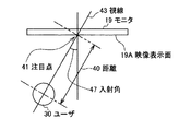
図2は、本実施形態の概要を説明するための図(その2)である。図2は、図1に示したモニタ19を上方から俯瞰した様子を示した図となっている。
FIG. 2 is a diagram (part 2) for explaining the outline of the present embodiment. FIG. 2 is a diagram showing a state where the
図2に示すように、ユーザ30がモニタ19上で注目している点を注目点41とする。注目点41は、ユーザ30の視線43とモニタ19の映像表示面19Aとの交点である。また、視線43の映像表示面19Aに対する入射角47、ユーザ30と注目点41との最短距離である距離40が規定されている。本実施形態では、入射角47、距離40のそれぞれに応じたエンハンス処理についても説明する。
As shown in FIG. 2, the point of interest of the
本実施形態では、表示装置(不図示)が、カメラ11(図1参照)を用いて、ユーザ30の視線43の方向を検出し、その方向に基づいて、モニタ19に出力する映像のエンハンス処理を行う。エンハンス処理では、注目点41に近い位置にあるモニタ19上の画素に高いゲイン量を設定する。これによって、ユーザ30にとって見やすく、かつ、遠近感がある映像をユーザ30に提供することができる。ここで、ゲイン量は、モニタ19を構成する各画素の明るさを示す値であり、色を構成する赤色、緑色、青色のそれぞれの輝度をいうものとする。
In the present embodiment, the display device (not shown) detects the direction of the line of sight 43 of the
《表示装置10の機能構成について》
図3は、本実施形態に係る表示装置の機能構成を示す機能構成図である。図3を参照して(適宜図1及び図2参照)、本実施形態に係る表示装置の機能構成について説明する。
<< Functional Configuration of
FIG. 3 is a functional configuration diagram illustrating a functional configuration of the display device according to the present embodiment. With reference to FIG. 3 (refer to FIG. 1 and FIG. 2 as appropriate), the functional configuration of the display device according to the present embodiment will be described.
図3に示すように、映像を表示する装置(テレビなど)である表示装置10は、少なくとも、カメラ11と、チューナ12と、ユーザ映像情報入力部110と、視線検出部120と、表示映像情報入力部150と、エンハンス処理部160と、表示映像出力制御部170と、モニタ19とを備える。また、図3に示すように、表示装置10は、ユーザ位置検出部130をさらに備えてもよいし、距離算出部140をさらに備えてもよい。
As shown in FIG. 3, a
カメラ11は、ユーザ30を撮影して、ユーザ30の映像情報を取得するものである。カメラ11は、図3に示したように、表示装置10に内蔵されているものでるとしてもよいし、表示装置10に外付けで接続できるものであってもよい。
The
ユーザ映像情報入力部110は、カメラ11によって取得された、モニタ19に表示される映像を見るユーザ30の映像情報であるユーザ映像情報の入力を受け付けるものである。ユーザ映像情報入力部110は、例えば、USB(Universal Serial Bus)インタフェース等によって構成される。
The user video
視線検出部120は、ユーザ映像情報入力部110が入力を受け付けたユーザ映像情報を解析してユーザ30の視線を検出するものである。ユーザ30の視線を検出する技術については、特に限定されるものではない。この技術は、例えば、「栗原謙三教授、[online]、[平成20年6月11日検索]、インターネット<URL:http://joint.idec.or.jp/koryu/020426_2.php>」等に記載されている。視線検出部120は、CPU(Central Processing Unit)等によって構成される。この場合には、CPUがROM(Read Only Memory)等に記憶されたプログラムをRAM(Random Access Memory)等に展開し、展開したRAM上のプログラムを実行することによって視線検出部120の機能が実現される。視線検出部120は、例えば、専用のハードウェア等によって構成されることとしてもよい。
The line-of-
チューナ12は、受信した電波から目的とする周波数の電波を選択して、選択した電波から、モニタ19に表示される映像を再生するものである。なお、チューナ12の代わりにDVD(digital versatile disk)プレーヤ等を用いて、映像を再生することとしてもよい。
The
表示映像情報入力部150は、モニタ19に表示される映像のもとになる表示映像情報の入力を受け付けるものである。表示映像情報入力部150は、例えば、専用のハードウェア等によって構成される。
The display video
エンハンス処理部160は、視線検出部120が検出したユーザ30の視線43とモニタ19の映像表示面19Aとの交点をユーザ30が注目している点である注目点41として検出するものである。また、エンハンス処理部160は、検出した注目点41との距離が大きい位置から小さい位置に向けて段階的に高いゲイン量を設定することでモニタ19に対するエンハンス処理を行うものである。
The
また、エンハンス処理部160は、ゲイン量を設定する際に、注目点41を中心とした1または複数の同心円によって区分けされる複数の領域のうち、注目点41との距離が大きい領域から小さい領域に向けて段階的に高いゲイン量を設定することとしてもよい。
In addition, when the
さらに、エンハンス処理部160は、ゲイン量を設定する際に、1または複数の同心円のそれぞれの半径が、所定の長さを増分として注目点41との距離を順次に増加させたものであるとしてもよい(図4参照)。所定の長さは、例えば、エンハンス処理部160が保持するものとする。
Further, when the
また、エンハンス処理部160は、ゲイン量を設定する際に、所定の長さがモニタ19を構成する隣り合う画素間の距離以下であるとしてもよい(図5参照)。これよって、注目点41を中心とした1または複数の同心円によって区分けされる複数の領域を狭くすることが可能となり、ユーザ30から見て連続的にゲイン量が変化するようになる。したがって、モニタ19に表示される映像に対してさらに自然に遠近感を生じさせることができる。
Further, when the
さらに、エンハンス処理部160は、ゲイン量を設定する際に、注目点41を中心とした1または複数の同心円が、モニタ19の縦横比と一致する比率を長軸短軸比(短軸の長さに対する長軸の長さの比)とする楕円であるとしてもよい(図6参照)。これよって、モニタ19の形状に合わせて、モニタ19に表示される映像に対して遠近感を生じさせることができる。モニタ19の縦横比については、例えば、縦:横=16:9等とすることができるが、特に限定されるものではない。
Furthermore, when setting the amount of gain, the
エンハンス処理部160は、CPU等によって構成される。この場合には、CPUがROM等に記憶されたプログラムをRAM等に展開し、展開したRAM上のプログラムを実行することによってエンハンス処理部160の機能が実現される。エンハンス処理部160は、例えば、専用のハードウェア等によって構成されることとしてもよい。
The
表示映像出力制御部170は、エンハンス処理部160が設定したゲイン量と表示映像情報入力部150が入力を受け付けた表示映像情報とに基づいて、モニタ19を介して映像を出力するものである。例えば、専用のハードウェア等によって構成される。
The display video
モニタ19は、映像を表示するものである。モニタ19は、図1に示したように、表示装置10に含まれるものであるとしてもよいし、表示装置10に外付けで接続できるものであってもよい。
The
ユーザ位置検出部130は、ユーザ30の位置を検出するものである。ユーザ30の位置を検出する技術については、図8を参照して後述するが、これに限定されるものではない。
The user
ユーザ位置検出部130は、CPU等によって構成される。この場合には、CPUがROM等に記憶されたプログラムをRAM等に展開し、展開したRAM上のプログラムを実行することによってユーザ位置検出部130の機能が実現される。ユーザ位置検出部130は、例えば、専用のハードウェア等によって構成されることとしてもよい。
The user
表示装置10がユーザ位置検出部130をさらに備えることとした場合には、エンハンス処理部160は、前記した技術とは異なる技術によって、ゲイン量を設定することが可能となる。この技術については、図7を参照して後述する。
When the
距離算出部140は、モニタ19とユーザ30との距離を算出するものである。モニタ19とユーザ30との距離を算出する技術の一例については、図9を参照して後述するが、これに限定されるものではない。
The
表示装置10が距離算出部140をさらに備えることとした場合には、エンハンス処理部160は、前記した技術とは異なる技術によって、ゲイン量を設定することが可能となる。すなわち、距離算出部140が算出したモニタ19とユーザ30との距離が大きくなるにしたがって、段階的に高いゲイン量を設定することが可能となる。これによって、比較的近くから見ている場合には、弱めのエンハンス処理を、比較的遠くから見ている場合には、強めのエンハンス処理をそれぞれ行うことで、どちらの場合でも、ユーザ30から見て、大差ない見栄えの映像を表示することができる。
When the
なお、ユーザ映像情報入力部110、視線検出部120、ユーザ位置検出部130、距離算出部140、表示映像情報入力部150、エンハンス処理部160、表示映像出力制御部170等は、LSI(Large Scale Integration)等によって構成され、表示装置10の中心デバイスである。
Note that the user video
《エンハンス処理部160が行うエンハンス処理について》
図4は、本実施形態に係るエンハンス処理部が行うエンハンス処理の一例(その1)を模式的に示す図である。図4を参照して、本実施形態に係るエンハンス処理部が行うエンハンス処理の一例について説明する。
<< Enhancement processing performed by the
FIG. 4 is a diagram schematically illustrating an example (No. 1) of enhancement processing performed by the enhancement processing unit according to the present embodiment. With reference to FIG. 4, an example of enhancement processing performed by the enhancement processing unit according to the present embodiment will be described.
図4を参照すると、基準線50の上側にはモニタ19を正面から見た場合の様子が模式的に示され、基準線50の下側にはモニタ19を上から見た場合の様子が模式的に示されている(図6及び図7についても同様)。
Referring to FIG. 4, a state when the
視線検出部120は、ユーザ30の視線43を検出する。また、エンハンス処理部160は、視線検出部120が検出したユーザ30の視線43とモニタ19の映像表示面19Aとの交点をユーザ30が注目している点である注目点41として検出する。また、エンハンス処理部160は、検出した注目点41との距離が大きい位置から小さい位置に向けて段階的に高いゲイン量を設定することでモニタ19に対するエンハンス処理を行う。ここで、図4に示した一例では、エンハンス処理部160は、ゲイン量を設定する際に、2つの同心円のそれぞれの半径が、所定の長さを増分として注目点41との距離を順次に増加させたものであるとしている。
The line-of-
図5は、本実施形態に係るエンハンス処理部が行うエンハンス処理の一例(その2)を模式的に示す図である。図5を参照して、本実施形態に係るエンハンス処理部が行うエンハンス処理の一例について説明する。 FIG. 5 is a diagram schematically illustrating an example (No. 2) of enhancement processing performed by the enhancement processing unit according to the present embodiment. With reference to FIG. 5, an example of enhancement processing performed by the enhancement processing unit according to the present embodiment will be described.
図5を参照すると、モニタ19を正面から見た場合の様子が示され、その下側には「不連続なゲインの掛け方」「連続なゲインの掛け方」のそれぞれについて表すグラフが示されている。
Referring to FIG. 5, a state of the
モニタ19には、注目点41を中心とした2つの同心円が示され、これらの同心円によって映像表示面19Aが3つの領域に区分けされている。注目点41との距離が大きい領域から小さい領域に向けて段階的に高いゲイン量を設定すると、図5に示したグラフ「不連続なゲインの掛け方」のように、エンハンス処理部160によって、不連続なゲイン量が設定される。なお、ここで、モニタ19に示された2つの同心円のそれぞれの半径は、所定の長さを増分として注目点41との距離を順次に増加させたものである。
The
エンハンス処理部160は、この所定の長さを小さくすることによって、ユーザ30から見て連続的に変化するようにゲイン量を設定することができる。例えば、この所定の長さを、モニタ19を構成する隣り合う画素間の距離以下とすればよい。そうすれば、図5に示したグラフ「連続なゲインの掛け方」のように、エンハンス処理部160によって、連続なゲイン量が設定される。
The
図6は、本実施形態に係るエンハンス処理部が行うエンハンス処理の一例(その3)を模式的に示す図である。図6を参照して、本実施形態に係るエンハンス処理部が行うエンハンス処理の一例について説明する。 FIG. 6 is a diagram schematically illustrating an example (part 3) of the enhancement processing performed by the enhancement processing unit according to the present embodiment. An example of enhancement processing performed by the enhancement processing unit according to the present embodiment will be described with reference to FIG.
図6に示した一例では、エンハンス処理部160は、ゲイン量を設定する際に、注目点41を中心とした2つの同心円が、モニタ19の縦横比と一致する比率を長軸短軸比とする楕円であるとしている。
In the example illustrated in FIG. 6, when the
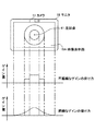
図7は、本実施形態に係るエンハンス処理部が行うエンハンス処理の一例(その4)を模式的に示す図である。図7を参照して、本実施形態に係るエンハンス処理部が行うエンハンス処理の一例について説明する。 FIG. 7 is a diagram schematically illustrating an example (part 4) of the enhancement processing performed by the enhancement processing unit according to the present embodiment. With reference to FIG. 7, an example of enhancement processing performed by the enhancement processing unit according to the present embodiment will be described.
図7に示した一例では、ユーザ位置検出部130によってユーザ30の位置が検出されている。このような場合には、エンハンス処理部160は、ゲイン量を設定する際に、ユーザ30の位置を基準点としてユーザ30の視線43と所定の角度をなす直線群とモニタ19の映像表示面19Aとの交点の集合を境界とする。図7に示した一例では、4本の補助線44のそれぞれが直線群に相当する。
In the example illustrated in FIG. 7, the position of the
エンハンス処理部160は、この角度を1または複数設定することで、境界によってモニタ19を複数の領域に区分けする。図7に示した一例では、この角度を2つ設定している。エンハンス処理部160は、この複数の領域のうち、注目点41との距離が大きい領域から小さい領域に向けて段階的に高いゲイン量を設定する。所定の角度は、例えば、エンハンス処理部160が保持するものとし、モニタ19の縦方向及び横方向において異なる角度を保持するものとしてもよい。
The
これによれば、ユーザ30がモニタ19から遠ざかると、モニタ19と補助線44との交点は変化し、それに伴って同心円も変化する。ユーザ30とモニタ19との距離が大きくなることで、同心円のサイズも大きくなる。例えば、最も内側の同心円領域におけるエンハンス処理の強さを同じにした場合、ユーザ30とモニタ19との距離が大きいと、相対的にエンハンス処理を強く行う領域のサイズも大きくなる。結果として、ユーザ30が見た見栄えを、ユーザ30とモニタ19との距離の大小に関わらず、ある程度一定にすることが可能となる。
According to this, when the
また、ユーザ30がモニタ19を斜めから見ている場合に、入射角47が大きくなるにつれて、前記した境界の形状は、長軸比が大きい楕円になる。したがって、ユーザ30がモニタ19を斜めから見ている場合であっても、モニタ19に表示される映像に対してさらに自然に遠近感を生じさせることができる。
Further, when the
《ユーザ位置検出部130が行うユーザ位置検出処理について》
図8は、本実施形態に係るユーザ位置検出部が行うユーザ位置検出処理の一例を模式的に示す図である。図8を参照して(適宜他の図参照)、本実施形態に係るユーザ位置検出部が行うユーザ位置検出処理の一例について説明する。
<< User position detection processing performed by the user
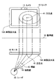
FIG. 8 is a diagram schematically illustrating an example of a user position detection process performed by the user position detection unit according to the present embodiment. With reference to FIG. 8 (refer to other figures as appropriate), an example of user position detection processing performed by the user position detection unit according to the present embodiment will be described.
図8は、カメラ11のレンズから見たユーザ30の様子を示すものである。図8には、さらに等距離線が追加されており、ズームなども一定とすると、モニタ19とユーザ30などのオブジェクトの距離は等距離線で表現される。図8に示すような映像をカメラ11が撮影し、その情報を、ユーザ映像情報入力部110を介してユーザ位置検出部130が取得し、解析する。ユーザ位置検出部130は、例えば、ユーザ映像情報入力部110が入力を受け付けたユーザ30の映像情報を解析することによって、検出したユーザ30の足元の位置を、ユーザ30の位置とすることができる。
FIG. 8 shows the state of the
エンハンス処理部160は、1または複数の角度のそれぞれが、所定の角度を増分として視線43となす角度を順次に増加させたものであるとして、ゲイン量を設定することとしてもよい。
The
《距離算出部140が行う距離算出処理について》
図9は、本実施形態に係る距離算出部が行う距離算出処理の一例を模式的に示す図である。図9を参照して、本実施形態に係る距離算出部が行う距離算出処理の一例について説明する。
<< Distance Calculation Process Performed by
FIG. 9 is a diagram schematically illustrating an example of a distance calculation process performed by the distance calculation unit according to the present embodiment. With reference to FIG. 9, an example of the distance calculation process performed by the distance calculation unit according to the present embodiment will be described.
図9に示すように、モニタ19に対するカメラ11の相対位置は確定している。したがって、この相対位置とユーザ位置検出部130が検出したカメラ11を基準位置としたユーザ30の相対位置とを用いて、モニタ19を基準位置としたユーザ30の位置を算出でき、距離40が算出できる。
As shown in FIG. 9, the relative position of the
エンハンス処理部160は、表示装置10が距離算出部140をさらに備える場合には、モニタ19とユーザ30との距離を考慮することで、その距離に応じた適切なエンハンス処理を行うことができる。例えば、モニタ19とユーザ30との距離が大きくなるにしたがって、段階的に高いゲイン量を設定することでモニタ19に対するエンハンス処理を行うことができる。このようにすれば、ユーザ30がモニタ19と離れていても鮮明な映像を見ることができる。
When the
《ユーザ30が複数存在する場合について》
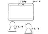
図10は、ユーザが複数存在する場合について説明するための図である。図10を参照して、ユーザが複数存在する場合について説明する。
<< When there are a plurality of
FIG. 10 is a diagram for explaining a case where there are a plurality of users. A case where there are a plurality of users will be described with reference to FIG.
図10には、ユーザ30が複数存在する場合の一例として、ユーザ30が2人存在する場合を示している。この場合には、ユーザ30が1人の場合の既存の処理を、2人分行うことで、より精度の高いエンハンス処理を行うことができる。
FIG. 10 shows a case where there are two
例えば、2人のユーザ30が同一の領域に視線を向けている場合には、その領域を中心により強いエンハンス処理を行うことができる。また、2人のユーザ30が別の領域に視線43を向けている場合には、それぞれの情報から異なる領域をエンハンス処理することも可能となる。この処理は三人以上のユーザ30が存在する場合にも同様に適用できる。
For example, when two
詳細には、視線検出部120は、複数の視線を複数のユーザ30それぞれの視線として検出することで、ユーザ30の視線を検出する。エンハンス処理部160は、視線検出部120が検出した複数のユーザ30それぞれの視線とモニタ19の映像表示面19Aとの交点を複数のユーザ30それぞれが注目している点である各注目点として検出する。エンハンス処理部160は、この各注目点から遠い位置から近い位置に向けて段階的に高いゲイン量をそれぞれ設定して、ゲイン量を各注目点について重ね合わせることで、エンハンス処理を行う。
Specifically, the line-of-
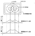
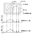
図11は、ユーザが複数存在する場合におけるゲインの掛け方について説明するための図である。図11を参照して、ユーザが複数存在する場合におけるゲインの掛け方について説明する。 FIG. 11 is a diagram for explaining how to apply gain when there are a plurality of users. With reference to FIG. 11, a description will be given of how to apply gain when there are a plurality of users.
図11を参照すると、2つの注目点41のそれぞれを中心とした同心円が重なっている。このような場合には、エンハンス処理部160が複数のユーザ30に対するゲイン量を別々に算出すると、それぞれのゲイン量は、図11の「重畳前のゲイン量」に示す通りになる。
When FIG. 11 is referred, the concentric circle centering on each of the two attention points 41 has overlapped. In such a case, when the
その後、エンハンス処理部160は、別々に算出した各ゲイン量を加算する。すなわち、各ゲイン量を重畳する。重畳した結果は、例えば、図11の「重畳後のゲイン量」に示す通りになる。但し、重畳した結果、重畳後のゲイン量が所定の範囲を超えたり、設定した閾値より大きくなったりした場合等には、重畳後のゲイン量に対して固定値の減算や1未満の値の乗算等の計算を施すことで、ゲイン量の調整を行うことができる。
Thereafter, the
《表示装置10が実行する処理の流れについて》
図12は、本実施形態に係る表示装置が実行する処理の流れを示すフローチャートである。図12を参照して(適宜他の図参照)、本実施形態に係る表示装置が実行する処理の流れについて説明する。なお、ここでは、ユーザ30がn人存在する場合を想定している。
<< Flow of processing executed by
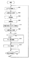
FIG. 12 is a flowchart showing a flow of processing executed by the display device according to the present embodiment. With reference to FIG. 12 (refer to other figures as appropriate), the flow of processing executed by the display device according to the present embodiment will be described. Here, it is assumed that there are
ユーザ映像情報入力部110は、カメラ11によって取得された、モニタ19に表示される映像を見るユーザ30の映像情報であるユーザ映像情報の入力を受け付ける。続いて、視線検出部120は、ユーザ映像情報入力部110が入力を受け付けたユーザ映像情報を解析してユーザ30の人数を検出する(ステップS101)。表示装置10は、視線検出部120が検出したユーザ30の人数(n人)分繰り返す処理(ステップS102〜ステップS106)を実行する。
The user video
繰り返し処理において、視線検出部120は、ユーザ30の視線43を検出する(ステップS103)。その後、距離算出部140は、ユーザ30とモニタ19との距離40を算出する(ステップS104)。エンハンス処理部160は、視線43と距離40とからモニタ19における各画素のゲイン量を算出する(ステップS105)。
In the iterative process, the line-of-
繰り返し処理が終わると、エンハンス処理部160は、ユーザ30の人数nが1より大きいか否かを判定する(ステップS107)。エンハンス処理部160は、ユーザ30の人数nが1より大きいと判定した場合には(ステップS107で「YES」)、算出したゲイン量を重畳し(ステップS108)、ステップS109に進む。エンハンス処理部160は、ユーザ30の人数nが1以下であると判定した場合には(ステップS107で「NO」)、ステップS109に進む。
When the iterative process ends, the
エンハンス処理部160は、ゲイン量を設定し(ステップS109)、所定時間が経過したか否かを判定する(ステップS110)。エンハンス処理部160は、所定時間が経過していないと判定した場合には(ステップS110で「NO」)、所定時間が経過するまで待機する。エンハンス処理部160は、所定時間が経過したと判定した場合には(ステップS110で「YES」)、ステップS101に戻って処理を繰り返す。
The
《カメラ11が複数存在する場合について》
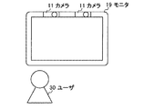
図13は、カメラが複数存在する場合について説明するための図である。図13を参照して、カメラが複数存在する場合について説明する。
<< When there are
FIG. 13 is a diagram for explaining a case where there are a plurality of cameras. A case where there are a plurality of cameras will be described with reference to FIG.
図13に示すように、カメラ11が複数存在する場合には、複数のカメラ11でユーザ30を撮影することで、ユーザ30の位置検出や視線43の検出において、より精度の高い検出を行うことが可能となることが期待できる。
As shown in FIG. 13, when there are a plurality of
《既存方式と組み合わせる場合について》
図14は、既存方式と本実施形態による方式とを組み合わせる場合について説明するための図である。図14を参照して、既存方式と本実施形態による方式とを組み合わせる場合について説明する。
<< When combining with existing methods >>
FIG. 14 is a diagram for explaining a case where the existing method and the method according to the present embodiment are combined. With reference to FIG. 14, the case where the existing system and the system by this embodiment are combined is demonstrated.
ここで、既存方式は、映像の内容に応じてゲイン量を設定する方式であるとする。図14に示すように、例えば、映像にビル19Bが含まれており、そのエッジについて既存方式でエンハンス処理が行われている。このような場合に、各方式でゲイン量を別々に算出すると、それぞれのゲイン量は、図14の「重畳前のゲイン量」に示す通りになる。
Here, it is assumed that the existing method is a method of setting the gain amount according to the content of the video. As shown in FIG. 14, for example, a
エンハンス処理部160は、既存方式によって設定されたゲイン量と本実施形態による方式によって設定されたゲイン量とを重畳する。重畳した結果は、例えば、図14の「重畳後のゲイン量」に示す通りになる。但し、重畳した結果、重畳後のゲイン量が所定の範囲を超えたり、設定した閾値より大きくなったりした場合等には、重畳後のゲイン量に対して固定値の減算や1未満の値の乗算等の計算を施すことで、ゲイン量の調整を行うことができる。
The
また、これに限らず、複数種類のエンハンス処理を複合して処理をすることが可能である。例えば、本実施形態による方式により、注目領域に対してエンハンス処理を行う方式を方式1する。また、映像自体の適応処理により顔の部分を検出し、その部分を、より好ましい映像にするために、エンハンス処理を弱くする処理を方式2とする。方式1と方式2との両方を考慮して、統合したエンハンス処理を行うことで、それぞれ別々にエンハンス処理を行うよりも、ユーザ30は、より好ましい映像を見ることができる。
Further, the present invention is not limited to this, and it is possible to perform processing by combining a plurality of types of enhancement processing. For example,
このように、映像自体に適応したエンハンス処理を行う既存方式と組み合わせることで、既存の方式の長所を確保したままエンハンス処理を行うことができる。 In this way, by combining with an existing method that performs enhancement processing adapted to the video itself, enhancement processing can be performed while securing the advantages of the existing method.
本実施形態によれば、ユーザ30自身が注目している注目点41を中心に、エンハンス処理の強弱を制御することで、映像自体の情報からエンハンス処理を行う場合と比較して、ユーザ30が嗜好するエンハンス処理を行うことができる。また、ユーザの視線に応じて遠近感のある映像を表示することが可能となる。
According to the present embodiment, by controlling the strength of the enhancement process around the attention point 41 that the
また、ユーザ30の位置や視線43を検出することで、正面から見ている場合と斜めから見ている場合など、異なる位置関係でも適切なエンハンス処理が可能となる。
Further, by detecting the position of the
上記では、添付図面を参照しながら本発明の好適な実施形態について説明したが、本発明は係る例に限定されないことは言うまでもない。当業者であれば、特許請求の範囲に記載された範疇内において、各種の変更例または修正例に想到し得ることは明らかであり、それらについても当然に本発明の技術的範囲に属するものと了解される。 In the above, the preferred embodiments of the present invention have been described with reference to the accompanying drawings, but it goes without saying that the present invention is not limited to such examples. It will be apparent to those skilled in the art that various changes and modifications can be made within the scope of the claims, and these are naturally within the technical scope of the present invention. Understood.
10 表示装置
11 カメラ
12 チューナ
19 モニタ
19A 映像表示面
19B ビル
30 ユーザ
40 距離
41 注目点
43 視線
44 補助線
47 入射角
50 基準線
110 ユーザ映像情報入力部
120 視線検出部
130 ユーザ位置検出部
140 距離算出部
150 表示映像情報入力部
160 エンハンス処理部
170 表示映像出力制御部
DESCRIPTION OF
Claims (10)
カメラによって取得された、前記モニタに表示される映像を見るユーザの映像情報であるユーザ映像情報の入力を受け付けるユーザ映像情報入力部と、
前記ユーザ映像情報入力部が入力を受け付けた前記ユーザ映像情報を解析して当該ユーザの視線を検出する視線検出部と、
前記視線検出部が検出した前記ユーザの視線と前記モニタの映像表示面との交点を前記ユーザが注目している点である注目点として検出し、当該注目点との距離が大きい位置から小さい位置に向けて段階的に高いゲイン量を設定することで前記モニタに対するエンハンス処理を行うエンハンス処理部と、
前記エンハンス処理部が設定した前記ゲイン量と前記表示映像情報入力部が入力を受け付けた前記表示映像情報とに基づいて、前記モニタを介して映像を出力する表示映像出力制御部と、
を備える、表示装置。 A display video information input unit that accepts input of display video information that is a source of video displayed on the monitor;
A user video information input unit that receives input of user video information, which is video information of a user who views the video displayed on the monitor, acquired by the camera;
A line-of-sight detection unit that analyzes the user video information received by the user video information input unit and detects the line of sight of the user;
An intersection between the user's line of sight detected by the line-of-sight detection unit and the video display surface of the monitor is detected as a point of interest, which is a point that the user is paying attention to. An enhancement processing unit that performs enhancement processing on the monitor by setting a high gain amount in a stepwise manner,
A display video output control unit for outputting video via the monitor based on the gain amount set by the enhancement processing unit and the display video information received by the display video information input unit;
A display device comprising:
前記注目点を中心とした1または複数の同心円によって区分けされる複数の領域のうち、前記注目点との距離が大きい領域から小さい領域に向けて段階的に高いゲイン量を設定することで、前記注目点との距離が大きい位置から小さい位置に向けて段階的に高いゲイン量を設定する、
請求項1に記載の表示装置。 The enhancement processing unit is
Of the plurality of regions divided by one or a plurality of concentric circles centered on the attention point, by setting a high gain amount in stages from a region having a large distance to the attention point to a small region, Set a high gain step by step from a position where the distance to the point of interest is large to a small position.
The display device according to claim 1.
前記1または複数の同心円のそれぞれの半径が、所定の長さを増分として前記注目点との距離を順次に増加させたものであるとして、前記ゲイン量を設定する、
請求項2に記載の表示装置。 The enhancement processing unit is
The gain amount is set on the assumption that the respective radii of the one or more concentric circles are obtained by sequentially increasing the distance from the point of interest by incrementing a predetermined length.
The display device according to claim 2.
前記所定の長さが前記モニタを構成する隣り合う画素間の距離以下であるとして、前記ゲイン量を設定する、
請求項3に記載の表示装置。 The enhancement processing unit is
The gain amount is set assuming that the predetermined length is equal to or less than a distance between adjacent pixels constituting the monitor.
The display device according to claim 3.
前記注目点を中心とした1または複数の同心円が、前記モニタの縦横比と一致する比率を長軸短軸比とする楕円であるとして、前記ゲイン量を設定する、
請求項2に記載の表示装置。 The enhancement processing unit is
The gain amount is set on the assumption that one or more concentric circles centered on the point of interest is an ellipse having a major axis / minor axis ratio equal to the aspect ratio of the monitor.
The display device according to claim 2.
前記エンハンス処理部は、
前記ユーザ位置検出部が検出した前記ユーザの位置を基準点として前記ユーザの視線と所定の角度をなす直線群と前記モニタの映像表示面との交点の集合を境界とし、前記角度を1または複数設定することで、前記境界によって前記モニタを複数の領域に区分けし、当該複数の領域のうち、前記注目点との距離が大きい領域から小さい領域に向けて段階的に高いゲイン量を設定することで、前記注目点との距離が大きい位置から小さい位置に向けて段階的に高いゲイン量を設定する、
請求項1に記載の表示装置。 A user position detecting unit for detecting the position of the user;
The enhancement processing unit is
With the user position detected by the user position detection unit as a reference point, a set of intersections between a group of straight lines that form a predetermined angle with the line of sight of the user and the video display surface of the monitor, and the angle is one or more By setting, the monitor is divided into a plurality of areas by the boundary, and a high gain amount is set stepwise from a large area to a small area among the plurality of areas. Then, a high gain amount is set stepwise from a position where the distance to the attention point is large to a small position.
The display device according to claim 1.
前記1または複数の角度のそれぞれが、所定の角度を増分として前記視線となす角度を順次に増加させたものであるとして、前記ゲイン量を設定する
請求項6に記載の表示装置。 The enhancement processing unit is
The display device according to claim 6, wherein the gain amount is set on the assumption that each of the one or more angles is obtained by sequentially increasing an angle formed with the line of sight by incrementing a predetermined angle.
前記エンハンス処理部は、
前記距離算出部が算出した前記モニタと前記ユーザとの距離が大きくなるにしたがって、段階的に高いゲイン量を設定することで前記モニタに対するエンハンス処理を行う、
請求項1乃至請求項7のいずれか1項に記載の表示装置。 A distance calculation unit for calculating a distance between the monitor and the user;
The enhancement processing unit is
As the distance between the monitor calculated by the distance calculation unit and the user increases, enhancement processing for the monitor is performed by setting a high gain amount in stages.
The display device according to claim 1.
複数の視線を複数のユーザそれぞれの視線として検出することで、前記ユーザの視線を検出し、
前記エンハンス処理部は、
前記視線検出部が検出した前記複数のユーザそれぞれの視線と前記モニタの映像表示面との交点を前記複数のユーザそれぞれが注目している点である各注目点として検出し、当該各注目点から遠い位置から近い位置に向けて段階的に高いゲイン量をそれぞれ設定し、当該ゲイン量を各注目点について重ね合わせることで、前記エンハンス処理を行う、
請求項1乃至請求項7のいずれか1項に記載の表示装置。 The line-of-sight detection unit
By detecting a plurality of gazes as a gaze for each of a plurality of users, the gaze of the user is detected,
The enhancement processing unit is
The intersection of the line of sight of each of the plurality of users detected by the line-of-sight detection unit and the video display surface of the monitor is detected as each point of interest that is a point that each of the plurality of users is paying attention to. A high gain amount is set stepwise from a distant position to a close position, and the enhancement processing is performed by superimposing the gain amount on each attention point.
The display device according to claim 1.
ユーザ映像情報入力部が、カメラによって取得された、前記モニタに表示される映像を見るユーザの映像情報であるユーザ映像情報の入力を受け付けるステップと、
視線検出部が、前記ユーザ映像情報入力部が入力を受け付けた前記ユーザ映像情報を解析して当該ユーザの視線を検出するステップと、
エンハンス処理部が、前記視線検出部が検出した前記ユーザの視線と前記モニタの映像表示面との交点を前記ユーザが注目している点である注目点として検出し、当該注目点との距離が大きい位置から小さい位置に向けて段階的に高いゲイン量を設定することで前記モニタに対するエンハンス処理を行うステップと、
表示映像出力制御部が、前記エンハンス処理部が設定した前記ゲイン量と前記表示映像情報入力部が入力を受け付けた前記表示映像情報とに基づいて、前記モニタを介して映像を出力するステップと、
を含む、表示方法。 A step in which a display video information input unit receives input of display video information which is a source of video displayed on a monitor;
A step of accepting input of user video information, which is video information of a user who views a video displayed on the monitor, acquired by a camera;
A step of detecting a line of sight of the user by analyzing the user video information received by the user video information input unit;
The enhancement processing unit detects an intersection between the user's line of sight detected by the line-of-sight detection unit and the video display surface of the monitor as a point of interest that is a point of interest by the user, and a distance from the point of interest is Performing enhancement processing on the monitor by setting a high gain amount in stages from a large position toward a small position;
A display video output control unit outputting a video via the monitor based on the gain amount set by the enhancement processing unit and the display video information received by the display video information input unit;
Including display method.
Priority Applications (5)
| Application Number | Priority Date | Filing Date | Title |
|---|---|---|---|
| JP2008173006A JP4743234B2 (en) | 2008-07-02 | 2008-07-02 | Display device and display method |
| US12/459,449 US8619195B2 (en) | 2008-07-02 | 2009-07-01 | Display apparatus and display method |
| CN2009101396823A CN101635861B (en) | 2008-07-02 | 2009-07-02 | Display apparatus and display method |
| EP09164394.0A EP2141921B1 (en) | 2008-07-02 | 2009-07-02 | Display apparatus and display method |
| US14/080,075 US8994883B2 (en) | 2008-07-02 | 2013-11-14 | Display apparatus and display method |
Applications Claiming Priority (1)
| Application Number | Priority Date | Filing Date | Title |
|---|---|---|---|
| JP2008173006A JP4743234B2 (en) | 2008-07-02 | 2008-07-02 | Display device and display method |
Publications (2)
| Publication Number | Publication Date |
|---|---|
| JP2010014836A true JP2010014836A (en) | 2010-01-21 |
| JP4743234B2 JP4743234B2 (en) | 2011-08-10 |
Family
ID=41172316
Family Applications (1)
| Application Number | Title | Priority Date | Filing Date |
|---|---|---|---|
| JP2008173006A Expired - Fee Related JP4743234B2 (en) | 2008-07-02 | 2008-07-02 | Display device and display method |
Country Status (4)
| Country | Link |
|---|---|
| US (2) | US8619195B2 (en) |
| EP (1) | EP2141921B1 (en) |
| JP (1) | JP4743234B2 (en) |
| CN (1) | CN101635861B (en) |
Cited By (5)
| Publication number | Priority date | Publication date | Assignee | Title |
|---|---|---|---|---|
| JP2013254358A (en) * | 2012-06-07 | 2013-12-19 | Sony Corp | Image processing apparatus, image processing method, and program |
| KR20150026564A (en) * | 2013-09-03 | 2015-03-11 | 엘지전자 주식회사 | Input module and image display device having the same |
| JP2019049705A (en) * | 2017-09-11 | 2019-03-28 | アップル インコーポレイテッドApple Inc. | Boundary gain system and method for electronic display |
| WO2019224868A1 (en) * | 2018-05-21 | 2019-11-28 | Necディスプレイソリューションズ株式会社 | Display device |
| US10642353B2 (en) | 2017-07-19 | 2020-05-05 | Fujitsu Limited | Non-transitory computer-readable storage medium, information processing apparatus, and information processing method |
Families Citing this family (17)
| Publication number | Priority date | Publication date | Assignee | Title |
|---|---|---|---|---|
| CN101894511B (en) * | 2010-07-15 | 2012-03-14 | 鸿富锦精密工业(深圳)有限公司 | Electronic looking board |
| US9800716B2 (en) | 2010-09-21 | 2017-10-24 | Cellepathy Inc. | Restricting mobile device usage |
| US11070661B2 (en) | 2010-09-21 | 2021-07-20 | Cellepathy Inc. | Restricting mobile device usage |
| US8750853B2 (en) | 2010-09-21 | 2014-06-10 | Cellepathy Ltd. | Sensor-based determination of user role, location, and/or state of one or more in-vehicle mobile devices and enforcement of usage thereof |
| CA2849725A1 (en) * | 2011-09-21 | 2013-03-28 | Cellepathy Ltd. | Restricting mobile device usage |
| CN102572217B (en) * | 2011-12-29 | 2014-08-20 | 华为技术有限公司 | Visual-attention-based multimedia processing method and device |
| US9691115B2 (en) | 2012-06-21 | 2017-06-27 | Cellepathy Inc. | Context determination using access points in transportation and other scenarios |
| KR102111407B1 (en) * | 2013-08-19 | 2020-05-15 | 엘지전자 주식회사 | Display apparatus and method for operating the same |
| KR102244620B1 (en) * | 2014-09-05 | 2021-04-26 | 삼성전자 주식회사 | Method and apparatus for controlling rendering quality |
| WO2016064366A1 (en) * | 2014-10-24 | 2016-04-28 | Echostar Ukraine, L.L.C. | Display device viewing angle compensation |
| CN106060658B (en) * | 2016-05-27 | 2019-06-14 | 青岛海信电器股份有限公司 | A kind of image processing method and device |
| US10714049B2 (en) | 2016-06-06 | 2020-07-14 | Apple Inc. | Electronic display border gain systems and methods |
| CN110710185B (en) * | 2017-06-03 | 2021-09-28 | 苹果公司 | Attention detection service |
| US10642335B2 (en) | 2017-06-03 | 2020-05-05 | Apple Inc. | Attention detection service |
| US11209656B1 (en) * | 2020-10-05 | 2021-12-28 | Facebook Technologies, Llc | Methods of driving light sources in a near-eye display |
| CN113115086B (en) * | 2021-04-16 | 2023-09-19 | 浙江闪链科技有限公司 | Method for collecting elevator media viewing information based on video line-of-sight identification |
| US11727892B1 (en) | 2022-11-09 | 2023-08-15 | Meta Platforms Technologies, Llc | Eye-tracking based foveation control of displays |
Citations (9)
| Publication number | Priority date | Publication date | Assignee | Title |
|---|---|---|---|---|
| JPH04192762A (en) * | 1990-11-26 | 1992-07-10 | Mitsubishi Electric Corp | Color television receiver |
| JPH10282877A (en) * | 1997-04-08 | 1998-10-23 | Canon Inc | Image forming method, its device, simulation system and storage medium |
| JP2000132152A (en) * | 1998-10-27 | 2000-05-12 | Sharp Corp | Display device |
| JP2002055675A (en) * | 1999-09-17 | 2002-02-20 | Matsushita Electric Ind Co Ltd | Image display device |
| JP2002116728A (en) * | 2000-10-10 | 2002-04-19 | Matsushita Electric Ind Co Ltd | Display device |
| JP2002175067A (en) * | 2000-12-05 | 2002-06-21 | Nissan Motor Co Ltd | Display device for automobile |
| JP2003202850A (en) * | 2001-10-04 | 2003-07-18 | Eastman Kodak Co | Method and system for displaying image |
| JP2005208182A (en) * | 2004-01-21 | 2005-08-04 | Sony Corp | Display control system and method, recording medium, and program |
| JP2005315956A (en) * | 2004-04-27 | 2005-11-10 | Pioneer Electronic Corp | Display unit driving device and driving method therefor |
Family Cites Families (16)
| Publication number | Priority date | Publication date | Assignee | Title |
|---|---|---|---|---|
| US2008301A (en) * | 1933-09-25 | 1935-07-16 | Stanley F Gleason | Meat processing and molding device |
| JPH01290385A (en) | 1988-05-17 | 1989-11-22 | Mitsubishi Electric Corp | Television receiver |
| JPH04132487A (en) | 1990-09-25 | 1992-05-06 | Matsushita Electric Ind Co Ltd | Television receiver, its controller and control method |
| JP2868389B2 (en) * | 1993-06-14 | 1999-03-10 | 株式会社エイ・ティ・アール通信システム研究所 | Image display device |
| JPH07287761A (en) * | 1994-04-19 | 1995-10-31 | Canon Inc | Device and method for processing picture |
| KR100265164B1 (en) | 1996-11-08 | 2000-09-15 | 윤종용 | Automatic contrast control circuit and method using distant measuring sensor |
| JP2000221953A (en) | 1999-01-29 | 2000-08-11 | Sony Corp | Image display device, image processing method, and image display system by applying them |
| CN1189026C (en) * | 1999-04-06 | 2005-02-09 | 皇家菲利浦电子有限公司 | Apparatus for processing signals |
| US6954193B1 (en) * | 2000-09-08 | 2005-10-11 | Apple Computer, Inc. | Method and apparatus for correcting pixel level intensity variation |
| JP2004213486A (en) | 2003-01-07 | 2004-07-29 | Sony Corp | Image processor and processing method, storage medium, and program |
| EP1768097A1 (en) * | 2004-06-18 | 2007-03-28 | Ueki, Makoto c/o Nec Corporation | Image display system, image display method, and image display program |
| DE102004057013A1 (en) * | 2004-11-25 | 2006-06-01 | Micronas Gmbh | Video display apparatus and method for processing a video signal to optimize image presentation |
| JP2006235307A (en) | 2005-02-25 | 2006-09-07 | Toshiba Corp | Display device and method of controlling display for the same |
| US7697751B2 (en) * | 2005-12-29 | 2010-04-13 | Graphics Properties Holdings, Inc. | Use of ray tracing for generating images for auto-stereo displays |
| US20080316372A1 (en) * | 2007-06-20 | 2008-12-25 | Ning Xu | Video display enhancement based on viewer characteristics |
| JP4858476B2 (en) | 2008-03-31 | 2012-01-18 | 株式会社日立製作所 | AC motor control device |
-
2008
- 2008-07-02 JP JP2008173006A patent/JP4743234B2/en not_active Expired - Fee Related
-
2009
- 2009-07-01 US US12/459,449 patent/US8619195B2/en active Active
- 2009-07-02 CN CN2009101396823A patent/CN101635861B/en active Active
- 2009-07-02 EP EP09164394.0A patent/EP2141921B1/en active Active
-
2013
- 2013-11-14 US US14/080,075 patent/US8994883B2/en active Active
Patent Citations (9)
| Publication number | Priority date | Publication date | Assignee | Title |
|---|---|---|---|---|
| JPH04192762A (en) * | 1990-11-26 | 1992-07-10 | Mitsubishi Electric Corp | Color television receiver |
| JPH10282877A (en) * | 1997-04-08 | 1998-10-23 | Canon Inc | Image forming method, its device, simulation system and storage medium |
| JP2000132152A (en) * | 1998-10-27 | 2000-05-12 | Sharp Corp | Display device |
| JP2002055675A (en) * | 1999-09-17 | 2002-02-20 | Matsushita Electric Ind Co Ltd | Image display device |
| JP2002116728A (en) * | 2000-10-10 | 2002-04-19 | Matsushita Electric Ind Co Ltd | Display device |
| JP2002175067A (en) * | 2000-12-05 | 2002-06-21 | Nissan Motor Co Ltd | Display device for automobile |
| JP2003202850A (en) * | 2001-10-04 | 2003-07-18 | Eastman Kodak Co | Method and system for displaying image |
| JP2005208182A (en) * | 2004-01-21 | 2005-08-04 | Sony Corp | Display control system and method, recording medium, and program |
| JP2005315956A (en) * | 2004-04-27 | 2005-11-10 | Pioneer Electronic Corp | Display unit driving device and driving method therefor |
Cited By (6)
| Publication number | Priority date | Publication date | Assignee | Title |
|---|---|---|---|---|
| JP2013254358A (en) * | 2012-06-07 | 2013-12-19 | Sony Corp | Image processing apparatus, image processing method, and program |
| KR20150026564A (en) * | 2013-09-03 | 2015-03-11 | 엘지전자 주식회사 | Input module and image display device having the same |
| KR102149200B1 (en) * | 2013-09-03 | 2020-08-28 | 엘지전자 주식회사 | Input module and image display device having the same |
| US10642353B2 (en) | 2017-07-19 | 2020-05-05 | Fujitsu Limited | Non-transitory computer-readable storage medium, information processing apparatus, and information processing method |
| JP2019049705A (en) * | 2017-09-11 | 2019-03-28 | アップル インコーポレイテッドApple Inc. | Boundary gain system and method for electronic display |
| WO2019224868A1 (en) * | 2018-05-21 | 2019-11-28 | Necディスプレイソリューションズ株式会社 | Display device |
Also Published As
| Publication number | Publication date |
|---|---|
| US8994883B2 (en) | 2015-03-31 |
| US20100002072A1 (en) | 2010-01-07 |
| JP4743234B2 (en) | 2011-08-10 |
| US8619195B2 (en) | 2013-12-31 |
| CN101635861B (en) | 2011-06-08 |
| EP2141921A1 (en) | 2010-01-06 |
| US20140071296A1 (en) | 2014-03-13 |
| EP2141921B1 (en) | 2021-12-15 |
| CN101635861A (en) | 2010-01-27 |
Similar Documents
| Publication | Publication Date | Title |
|---|---|---|
| JP4743234B2 (en) | Display device and display method | |
| US8908991B2 (en) | Image processing apparatus, image processing method and storage medium | |
| JP6167703B2 (en) | Display control device, program, and recording medium | |
| US10317777B2 (en) | Automatic zooming method and apparatus | |
| JP6131948B2 (en) | Display control apparatus, display control method, and program | |
| JP2011170840A (en) | Image processing device and electronic apparatus | |
| JP2008269396A (en) | Image processor, image processing method, and program | |
| JP5886242B2 (en) | Image processing apparatus, image processing method, and image processing program | |
| WO2013084593A1 (en) | Image processing device, image processing method, and program | |
| WO2013111552A1 (en) | Image processor, imaging device, and image processing method | |
| JP6486055B2 (en) | Imaging apparatus, control method therefor, and program | |
| JP5974205B1 (en) | Image processing apparatus and method of operating image processing apparatus | |
| JP2017212638A (en) | Display device, control method for display device, and program | |
| JP2011013334A (en) | Image display device | |
| JP6103942B2 (en) | Image data processing apparatus and image data processing program | |
| TWI516120B (en) | Method for generating panoramic image and image capturing device thereof | |
| JP6347604B2 (en) | Image projection apparatus, image projection method and program | |
| WO2017216933A1 (en) | Image processing device, image processing method and image processing program | |
| JP2009282736A (en) | Image processor, method and program for image processing | |
| JP2018041201A (en) | Display control program, display control method and information processing device | |
| JP2009211607A (en) | Object extraction device and method | |
| JP6489733B2 (en) | Image output apparatus, image output method, and program | |
| TW202345097A (en) | Recommendations for image capture | |
| JP5448223B2 (en) | Image color conversion device, display device, image color conversion method, and image color conversion program | |
| JP2018078443A (en) | Display control device, display control method, and display device |
Legal Events
| Date | Code | Title | Description |
|---|---|---|---|
| A977 | Report on retrieval |
Free format text: JAPANESE INTERMEDIATE CODE: A971007 Effective date: 20100412 |
|
| A131 | Notification of reasons for refusal |
Free format text: JAPANESE INTERMEDIATE CODE: A131 Effective date: 20100420 |
|
| A521 | Request for written amendment filed |
Free format text: JAPANESE INTERMEDIATE CODE: A523 Effective date: 20100618 |
|
| A131 | Notification of reasons for refusal |
Free format text: JAPANESE INTERMEDIATE CODE: A131 Effective date: 20110111 |
|
| A521 | Request for written amendment filed |
Free format text: JAPANESE INTERMEDIATE CODE: A523 Effective date: 20110228 |
|
| TRDD | Decision of grant or rejection written | ||
| A01 | Written decision to grant a patent or to grant a registration (utility model) |
Free format text: JAPANESE INTERMEDIATE CODE: A01 Effective date: 20110412 |
|
| A61 | First payment of annual fees (during grant procedure) |
Free format text: JAPANESE INTERMEDIATE CODE: A61 Effective date: 20110425 |
|
| FPAY | Renewal fee payment (event date is renewal date of database) |
Free format text: PAYMENT UNTIL: 20140520 Year of fee payment: 3 |
|
| R151 | Written notification of patent or utility model registration |
Ref document number: 4743234 Country of ref document: JP Free format text: JAPANESE INTERMEDIATE CODE: R151 |
|
| FPAY | Renewal fee payment (event date is renewal date of database) |
Free format text: PAYMENT UNTIL: 20140520 Year of fee payment: 3 |
|
| R250 | Receipt of annual fees |
Free format text: JAPANESE INTERMEDIATE CODE: R250 |
|
| R250 | Receipt of annual fees |
Free format text: JAPANESE INTERMEDIATE CODE: R250 |
|
| R250 | Receipt of annual fees |
Free format text: JAPANESE INTERMEDIATE CODE: R250 |
|
| R250 | Receipt of annual fees |
Free format text: JAPANESE INTERMEDIATE CODE: R250 |
|
| R250 | Receipt of annual fees |
Free format text: JAPANESE INTERMEDIATE CODE: R250 |
|
| R250 | Receipt of annual fees |
Free format text: JAPANESE INTERMEDIATE CODE: R250 |
|
| R250 | Receipt of annual fees |
Free format text: JAPANESE INTERMEDIATE CODE: R250 |
|
| R250 | Receipt of annual fees |
Free format text: JAPANESE INTERMEDIATE CODE: R250 |
|
| R250 | Receipt of annual fees |
Free format text: JAPANESE INTERMEDIATE CODE: R250 |
|
| LAPS | Cancellation because of no payment of annual fees |