JP2010014700A - Image radar device - Google Patents
Image radar device Download PDFInfo
- Publication number
- JP2010014700A JP2010014700A JP2009035619A JP2009035619A JP2010014700A JP 2010014700 A JP2010014700 A JP 2010014700A JP 2009035619 A JP2009035619 A JP 2009035619A JP 2009035619 A JP2009035619 A JP 2009035619A JP 2010014700 A JP2010014700 A JP 2010014700A
- Authority
- JP
- Japan
- Prior art keywords
- reflection point
- calculated
- change rate
- phase difference
- angular velocity
- Prior art date
- Legal status (The legal status is an assumption and is not a legal conclusion. Google has not performed a legal analysis and makes no representation as to the accuracy of the status listed.)
- Granted
Links
- 230000005540 biological transmission Effects 0.000 claims abstract description 33
- 230000001133 acceleration Effects 0.000 claims description 79
- 230000033001 locomotion Effects 0.000 claims description 69
- 239000013598 vector Substances 0.000 claims description 49
- 238000000605 extraction Methods 0.000 claims description 38
- 238000000034 method Methods 0.000 claims description 37
- 230000000875 corresponding effect Effects 0.000 claims description 24
- 239000011159 matrix material Substances 0.000 claims description 17
- 230000002596 correlated effect Effects 0.000 claims description 8
- 238000000354 decomposition reaction Methods 0.000 claims description 5
- 230000002194 synthesizing effect Effects 0.000 claims description 5
- 230000015572 biosynthetic process Effects 0.000 claims description 2
- 238000003786 synthesis reaction Methods 0.000 claims description 2
- 230000001678 irradiating effect Effects 0.000 claims 1
- 238000010586 diagram Methods 0.000 description 30
- 230000000694 effects Effects 0.000 description 10
- 230000006870 function Effects 0.000 description 10
- 230000014509 gene expression Effects 0.000 description 7
- 238000001514 detection method Methods 0.000 description 5
- 230000017105 transposition Effects 0.000 description 2
- 238000009825 accumulation Methods 0.000 description 1
- 230000002123 temporal effect Effects 0.000 description 1
Images


Landscapes
- Radar Systems Or Details Thereof (AREA)
Abstract
Description
この発明は、送信電波と反射電波からなる受信電波とに基づき遠方の目標を観測して、目標の形状、反射強度分布、種類などを特定する画像レーダ装置に関するものである。 The present invention relates to an image radar apparatus that observes a distant target based on a transmitted radio wave and a received radio wave composed of a reflected radio wave and identifies the shape, reflection intensity distribution, type, and the like of the target.
従来の画像レーダ装置においては、異なる時刻に送受信された電波から得られる2枚のレーダ画像(以下、単に「画像」ともいう)を比較して、レーダ画像上の輝点の画像上での速度分布を収集し、適当な方法で画像レーダ装置と目標との相対運動を推定したうえで、相対運動情報を用いて目標上の電波反射点の3次元空間における位置を算出することにより、目標の3次元形状を得ている(例えば、特許文献1参照)。 In a conventional image radar device, two radar images (hereinafter also simply referred to as “images”) obtained from radio waves transmitted and received at different times are compared, and the speed on the image of the bright spot on the radar image is compared. The distribution is collected, the relative motion between the image radar device and the target is estimated by an appropriate method, and the position of the wave reflection point on the target is calculated in the three-dimensional space using the relative motion information. A three-dimensional shape is obtained (see, for example, Patent Document 1).
レーダ画像は、目標の三次元形状を、レーダの視線方向と目標の相対運動で決まる二次元の投影面に投影したものとして得られる。レーダの観測においては、目標は、電波を反射する複数の孤立反射点の集合と考えることが出来る。レーダ画像においては、これらの孤立反射点の位置を二次元平面に投影した位置に、輝点が現れる。 The radar image is obtained by projecting the three-dimensional shape of the target onto a two-dimensional projection plane determined by the direction of the line of sight of the radar and the relative motion of the target. In radar observation, a target can be considered as a set of a plurality of isolated reflection points that reflect radio waves. In the radar image, bright spots appear at positions where these isolated reflection points are projected onto a two-dimensional plane.
ところで、レーダ画像を用いて目標の三次元形状を推定するためには、レーダ画像の投影面の向きを知る必要がある。前述の通り、レーダ画像の投影面の向きを決定する要素の一つに、レーダと目標の相対運動が含まれるが、三次元形状を推定する従来の画像レーダ装置においては、レーダと目標との相対運動の推定方法が明確に設定されておらず、画像レーダ装置以外の何らかの手段で画像レーダ装置と目標との相対運動を別途推定する必要があった。特に、ISAR(Inverse Synthetic Aperture Radar)方式によるレーダ画像生成の際は、目標運動は一般に未知であり、目標の相対運動を事前に推定するのは困難であった。 By the way, in order to estimate the target three-dimensional shape using the radar image, it is necessary to know the direction of the projection plane of the radar image. As described above, one of the factors that determine the direction of the projection plane of the radar image includes the relative motion between the radar and the target. In the conventional image radar device that estimates the three-dimensional shape, the radar and the target are not aligned. The relative motion estimation method is not clearly set, and it is necessary to separately estimate the relative motion between the image radar apparatus and the target by some means other than the image radar apparatus. In particular, when a radar image is generated by an ISAR (Inverse Synthetic Aperture Radar) method, the target motion is generally unknown, and it is difficult to estimate the relative motion of the target in advance.
この発明は、上記課題を解決するためになされたものであり、目標の相対運動と3次元形状を推定することのできる画像レーダ装置を得ることを目的とする。 The present invention has been made to solve the above-described problems, and an object thereof is to obtain an image radar apparatus capable of estimating a target relative motion and a three-dimensional shape.
この発明に係る画像レーダ装置は、目標に対して送信電波を照射する送信手段と、前記送信電波が前記目標で反射された反射電波を受信する、互いに異なる位置に配置された複数の受信用アンテナおよび受信機と、前記複数の受信用アンテナおよび受信機で受信された前記受信電波に基づき、前記目標のレーダ動画像を再生するレーダ画像再生部と、前記レーダ画像再生部で連続的に再生された複数のレーダ動画像を用いて目標の運動及び形状を推定する目標運動・形状推定手段とを備えたものである。 An image radar apparatus according to the present invention includes: a transmission unit that irradiates a target with a transmission radio wave; and a plurality of reception antennas that are arranged at different positions that receive the reflected radio wave reflected from the target. And the receiver, the plurality of receiving antennas and the received radio waves received by the receiver, the radar image reproducing unit for reproducing the target radar moving image, and the radar image reproducing unit And target motion / shape estimation means for estimating the motion and shape of the target using a plurality of radar moving images.
この発明によれば、複数のレーダ動画像から観測された視線方向の位置およびドップラー周波数に加えて、観測信号の位相差の情報を利用できるように構成したので、目標の運動と三次元形状を同時に推定することが可能となる。 According to the present invention, in addition to the position of the line of sight and the Doppler frequency observed from a plurality of radar moving images, the information on the phase difference of the observation signal can be used. It is possible to estimate at the same time.
実施の形態1.
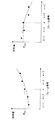
図1は、この発明の実施の形態1に係る画像レーダ装置の機能構成を示すブロック図である。また、図2乃至図4はこの発明の実施の形態1に係る画像レーダ装置の動作原理を説明するための説明図である。以下では、まず、図2乃至図4を用いて、本実施の形態1に係る画像レーダ装置の動作原理を説明する。なお、本明細書においては、画像レーダの方式としてISAR方式を対象として記載するが、SAR(Synthetic Aperture Radar)方式や、その他の画像レーダ方式を用いたものについても、同様の原理が成立することは明らかである。
1 is a block diagram showing a functional configuration of an image radar apparatus according to
図2は、観測のジオメトリを示す図である。まず、目標は複数の孤立反射点から成る一つの剛体と考える。図2において、19はこの目標を構成する孤立反射点のうちの一つPk(k=1,2,・・・,K;Kは孤立反射点の数)の位置を示す。また、孤立反射点Pkの位置ベクトルを FIG. 2 is a diagram showing an observation geometry. First, the target is a single rigid body consisting of a plurality of isolated reflection points. In FIG. 2, 19 indicates the position of one of the isolated reflection points P k (k = 1, 2,..., K; K is the number of isolated reflection points) constituting this target. Also, the position vector of the isolated reflection point P k is
![]()
![]()
とする。 And
次に、ここでは、目標が等角速度運動をしていることを前提とし、その角速度ベクトルを Next, here, assuming that the target is moving at an angular velocity, the angular velocity vector is
![]()
![]()
とする。 And
また、図2において、20は目標の回転を表す角速度ベクトル In FIG. 2, 20 is an angular velocity vector representing the target rotation.
![]()
![]()
を表す。一般に、船舶や航空機などの目標が等角速度運動を続けることはないが、短い時間の間、近似的に等角速度運動をしているとみなすことは可能である。また、図2において、21は孤立反射点Pkの速度を表すベクトル Represents. In general, a target such as a ship or an aircraft does not continue a constant angular velocity motion, but it can be regarded as performing a uniform angular velocity motion for a short time. In FIG. 2, 21 is a vector representing the speed of the isolated reflection point Pk.
![]()
![]()
である。目標上の孤立反射点は全て同じ角速度で運動するため、各孤立反射点の速度 It is. All isolated reflection points on the target move at the same angular velocity, so the speed of each isolated reflection point
![]()
![]()
は、次式で表される。 Is expressed by the following equation.

また、図2に示すとおり、目標回転軸上の任意の点Oを原点とする直交座標系x、y、z座標を定義する。x、y、z座標の軸の向きは任意であるが、例えばx、y平面が水平面を表し、zが鉛直方向上向きを表すと考えて良い。 Further, as shown in FIG. 2, orthogonal coordinate systems x, y, and z coordinates with an arbitrary point O on the target rotation axis as the origin are defined. The directions of the axes of the x, y, and z coordinates are arbitrary. For example, it may be considered that the x, y plane represents a horizontal plane, and z represents a vertical upward direction.
なお、本明細書において、 In this specification,
![]()
![]()
のように上線のついた変数は空間内のベクトルを表し、 An overlined variable such as represents a vector in space,
![]()
![]()
は変数xの時間微分を表す。また、 Represents the time derivative of the variable x. Also,
![]()
![]()
のように二重上線のついた変数は行列を表し、 A variable with a double overline represents a matrix,
![]()
![]()
のように like
![]()
![]()
記号のついた変数は長さが1の単位ベクトルを表す。
A variable with a symbol represents a unit vector of
図2において、3、4、5はそれぞれ送受信アンテナと受信用補助アンテナの位置を表している。また、送受信アンテナ3、受信用補助アンテナ4、受信用補助アンテナ5の位置ベクトルを、それぞれ、
In FIG. 2, 3, 4, and 5 represent the positions of the transmission / reception antenna and the reception auxiliary antenna, respectively. Further, the position vectors of the transmission /
![]()
![]()
とする。さらに、送受信アンテナ3からそれぞれ受信用補助アンテナ4と受信用補助アンテナ5へ向かうベクトルを基線ベクトルと呼び、次式で定義する。
And Furthermore, vectors from the transmitting / receiving
また、図2において、22は、送受信アンテナ3から原点に向かう方向(レーダの視線方向と一致するものとする)を表す単位ベクトルであり、次式で定義される。
In FIG. 2, 22 is a unit vector representing a direction from the transmitting / receiving
なお、以下では、送受信アンテナ3から目標までの距離
In the following, the distance from the transmitting / receiving
![]()
![]()
が、基線ベクトルの長さと目標のサイズに対して十分に長いものとする。 Is sufficiently long with respect to the length of the baseline vector and the target size.
![]()
![]()
観測において、送受信アンテナ3は、繰り返し周期(PRI:Pulse Repetition Interval)tpriで広帯域パルスの送受信を繰り返す。また、送受信アンテナ3と同時に受信用補助アンテナ4および受信用補助アンテナ5においても信号を受信する。すると、各アンテナで受信された信号を用いてそれぞれISARの動画像を再生することができる。
In the observation, the transmission /
図3は、各アンテナで受信された信号を用いて得られるISAR動画像の概念図である。図3において、23、24、25は送受信アンテナ3、受信用補助アンテナ4、受信用補助アンテナ5の受信信号を用いてそれぞれ再生されたISAR動画像である。ISAR動画像の1枚目のフレームは、1パルス目からHパルス目のデータを用いて生成され、2フレーム目は1+Jパルス目からH+Jパルス目を用いて生成されるものとする。3フレーム目以降も同様で、結局、nフレーム目は1+(n−1)Jパルス目からH+(n−1)Jパルス目のデータを用いて生成される。このとき、動画像のフレーム間の時間間隔tfrは次式で表される。
FIG. 3 is a conceptual diagram of an ISAR moving image obtained using a signal received by each antenna. In FIG. 3,
![]()
![]()
また、目標の運動および3次元形状を推定するのに用いる動画像のフレーム数をNとすると、全体の観測に必要な送信パルス数はH+(N−1)Jパルスであり、観測時間は{H+(N−1)J}tpriである。 If the number of frames of the moving image used for estimating the target motion and the three-dimensional shape is N, the number of transmission pulses necessary for the entire observation is H + (N−1) J pulses, and the observation time is { H + (N-1) J} t pri .
上記の観測およびISAR処理の結果、動画像23、24、25のn番目のフレームにおいて、孤立反射点Pkに対応する輝点が現れるものとする。すると、このフレームにおける輝点の座標の読み取り値から孤立反射点Pkのレーダの視線方向の位置rknとドップラー周波数fdkn、および輝点のピーク複素振幅s0kn、s1kn、s2knが観測される(図3参照)。ここで、厳密には各アンテナから孤立反射点Pkまでの距離や、各アンテナで観測されるドップラー周波数は異なるが、式(5)の条件より、rknとfdknは送受信アンテナ3における観測量で代表できるものとする。
As a result of the above observation and ISAR processing, a bright spot corresponding to the isolated reflection point P k appears in the nth frame of the moving
以下では、これらの観測量と、求めたい未知パラメータ Below, these observations and the unknown parameters you want to find
![]()
![]()
および and
![]()
![]()
との関係を導く。まず、rknとfdknは次式の関係を満たす。 To guide the relationship. First, r kn and f dkn satisfy the relationship of the following equation.
ただし、ISAR画像上におけるレンジ方向の原点の位置は、空間内に定義した原点Oであるとして定義した。なお、孤立反射点の位置 However, the position of the origin in the range direction on the ISAR image is defined as the origin O defined in the space. The position of the isolated reflection point
![]()
![]()
は当然時変であるが、以下ではn番目のフレームの観測時(より具体的には、 Is naturally time-varying, but in the following, when observing the nth frame (more specifically,
![]()
![]()
パルス目の送受信時;ただし, During transmission / reception of the pulse; however,
![]()
![]()
は小数点以下の切り捨てを表す)における位置を Represents the truncation after the decimal point)
![]()
![]()
と考える。 I think.
次に、ピーク複素振幅s0kn、s1kn、s2knについては、これらの観測値の間の位相差と Next, for the peak complex amplitudes s 0kn , s 1kn , s 2kn , the phase difference between these observations and
![]()
![]()
が次式の関係を満たす。 Satisfies the relationship of the following equation.
なお、式(9)と式(10)は、アレイアンテナを用いて遠方からの到来波を受信する際に、その到来角度によって決まるアレイ素子間の位相差の式に他ならない。目標の回転に伴い、 Equations (9) and (10) are nothing but equations for the phase difference between array elements determined by the arrival angle when receiving an incoming wave from a distance using an array antenna. As the target rotates,
![]()
![]()
が変化するため、φ1kn、φ2knは変化するが、短い時間の間ではその変化はほぼ線形とみなすことができ、その変化率は次式で表される。
Changes,
ここで、式(11)、式(12)の導出には以下の関係および近似を用いた。 Here, the following relationships and approximations were used to derive the equations (11) and (12).
なお、 In addition,
![]()
![]()
のとき、送受信アンテナ3から各孤立反射点への方向はほぼ平行であるため、次式の近似が成り立つ。
In this case, since the directions from the transmitting / receiving
また、位相差の変化率 Also, the rate of change of phase difference
![]()
![]()
は、n番目のフレームの前後のNフレームにおける位相差の値 Is the value of the phase difference in N frames before and after the nth frame
![]()
![]()
を用い、式(15)、(16)で表される最小二乗法による直線あてはめによって推定できる。 And can be estimated by straight-line fitting by the least square method expressed by the equations (15) and (16).
なお、ここで、 Where
![]()
![]()
は小数点以下の切り捨て、 Is rounded down
![]()
![]()
は小数点以下の切り上げをそれぞれ表す。 Represents rounding up after the decimal point.
図4は、観測された位相差の値に直線を当てはめて式(15)、(16)に示す位相差の変化率を求める概念図である。 FIG. 4 is a conceptual diagram for obtaining the change rate of the phase difference shown in the equations (15) and (16) by applying a straight line to the observed phase difference value.
原理的には、上記で導いた式(1)、(7)、(8)、(11)、(12)の関係を用いて、目標の運動および三次元形状を推定することが可能である。以下では、図1を用いて、この発明の実施の形態1に係る画像レーダ装置の機能構成および動作について説明する。
In principle, it is possible to estimate the target motion and three-dimensional shape using the relationships of the equations (1), (7), (8), (11), and (12) derived above. . Hereinafter, the functional configuration and operation of the image radar apparatus according to
図1に示す画像レーダ装置は、送信機1、送受切換器2、送受信アンテナ3、受信用補助アンテナ4及び5、受信機6〜8、レーダ画像生成部9、画像履歴蓄積部10、目標運動・形状推定部11及び表示部18を備えている。ここで、目標運動・形状推定部11は、反射点抽出部12、フレーム間反射点対応部13、位相差算出部14、位相差変異算出部15、反射点速度算出部16、目標形状・角速度算出部17を有し、目標形状・角速度算出部17で算出された結果は表示部18で表示される。
1 includes a
送信機1は、周知の発振器および変調器などを含み、送受切換器2および受信機6〜8とともに、送受信制御部(図示せず)の制御下で駆動される。送受信アンテナ3は、目標に向けて送信パルスを出射するとともに、送信パルスが目標で反射されて戻ってくる反射電波を受信電波として受信する。このとき、受信用補助アンテナ4と5も同時に該反射電波を受信電波として受信する。
The
受信機6〜8は、それぞれ送受信アンテナ3および受信用補助アンテナ4、5で受信された電波を増幅、検波して得られた受信信号をレーダ画像再生部9に送る。そして、前述の通り、本実施の形態1に係る画像レーダ装置においては、以上のようなパルスの送受信を繰返し周期tpriで繰り返す。
The
レーダ画像再生部9では、前述の通り、それぞれ送受信アンテナ3、受信用補助アンテナ4、受信用補助アンテナ5の受信信号を用いてISAR動画像23、24、25を再生する。ここで、nフレーム目を再生するためには1+(n−1)Jパルス目からH+(n−1)Jパルス目のデータを用いる。
As described above, the radar
画像履歴蓄積部10では、レーダ画像再生部9で再生された動画像23、24、25をメモリに蓄積する。目標運動・形状推定部11は、画像履歴蓄積部10に一旦格納された動画像23、24、25の情報を利用して、目標の運動と形状を推定して、推定結果の形状を表示部18に出力する。
The image
以下では、目標運動・形状推定部11の構成と動作を説明する。まず、反射点抽出部12では、動画像の各フレームにおいて、輝点(輝度の強い点)を検出し、その位置と複素振幅を計測する。輝点の検出には一般に良く知られたCFAR(Constant False Alarm Rate)処理などを用いればよい。以下では、反射点抽出部12において、動画像の各フレームにおいてK点ずつの点目標が検出されたと仮定して説明を進める。反射点抽出部12は、検出処理の結果として、K点の点目標について、レーダの視線方向の位置rknとドップラー周波数fdkn、および輝点のピーク複素振幅s0kn、s1kn、s2knを出力する(k=1,2,・・・,K)。
Below, the structure and operation | movement of the target motion and shape
フレーム間反射点対応部13では、各フレームで検出された輝点同士を対応付ける。ここでは、レーダの目標追尾などに利用される追尾方式などを利用して対応付けを行う。反射点抽出部12の出力結果において、n+1フレーム目におけるk番目の輝点の信号と、nフレーム目におけるk番目の輝点の信号が、同じ孤立反射点からの信号に対応しているとは限らない。フレーム間反射点対応部13における対応付け処理(追尾処理)によって、フレーム間での輝点の対応付けがなされ、その結果、同じ孤立反射点Pkの信号が全てのフレームにおいて、k番目の信号としてラベル付けされる。
The inter-frame reflection
なお、反射点抽出部12において、全てのフレームにおいて点目標が必ずK点検出されるとは限らない。例えば、n番目のフレームにおいてK点検出されていて、n+1番目のフレームにおいてK−1点しか検出されなければ、n番目で検出された輝点のうち一つは、n+1番目のフレームで検出された輝点と対応付けられないことになる。このような場合は、フレーム間反射点対応部13において対応付けできない旨を判定して記録する。
In the reflection
次いで、位相差算出部14では、送受信アンテナ3と、受信用補助アンテナ4,5で得られた信号の位相差を、各フレーム、各検出信号に対して次式によって算出する。
Next, the phase
次に、位相差変化率算出部15は、各フレーム、各検出信号に対して次式に示す位相差の変化率を算出する。
Next, the phase difference change
なお、位相差変化率算出部15における上記の最小二乗法による変化率の算出の代わりに、各輝点の反射強度(反射電力や振幅など)で重み付けを行い、重み付け最小二乗法によって変化率を算出しても良い。重み付けをすることによって、SNR(Signal to Noise Ratio)の高い信号の情報をより重視することが出来、位相差変化率の推定精度を向上することが可能である。
Instead of calculating the change rate by the least square method in the phase difference change
次に、反射点速度算出部16は、各孤立反射点の速度
Next, the reflection point
![]()
![]()
を求める。反射点速度算出部16の処理を説明するために、まず、式(8)、(11)、(12)を整理してまとめると次式を得る。
Ask for. In order to explain the processing of the reflection point
ただし、上付きのTは行列の転置を表す。ここで、行列 However, the superscript T represents transposition of a matrix. Where the matrix
![]()
![]()
を構成する要素は、レーダの視線方向ベクトル Are the radar gaze direction vectors
![]()
![]()
と基線ベクトル And baseline vector
![]()
![]()
であり、これらは既知であると考えることができる。また、左辺を構成する要素はレンジrkn、ドップラー周波数fdknと位相差の変化率 And these can be considered known. The elements constituting the left side are the range r kn , the Doppler frequency f dkn, and the change rate of the phase difference
![]()
![]()
であるが、レンジrkn、ドップラー周波数fdknは、反射点抽出部12の出力(ただし、フレーム間反射点対応部13によってラベル付けされたもの)として得られており、位相差の変化率 However, the range r kn and the Doppler frequency f dkn are obtained as the output of the reflection point extraction unit 12 (however, labeled by the inter-frame reflection point corresponding unit 13), and the change rate of the phase difference
![]()
![]()
は位相差変化率算出部15の出力として得られている。さらに、原点までの距離r0と波長λも含まれるが、これらは既知の値として扱うことができる。
Is obtained as an output of the phase difference change
以上より、反射点速度算出部16は、各孤立反射点の速度
From the above, the reflection point
![]()
![]()
を次式によって求める。 Is obtained by the following equation.
目標形状・角速度算出部17は、角速度
The target shape / angular
![]()
![]()
および各孤立反射点の位置 And the position of each isolated reflection point
![]()
![]()
を算出する。以下に、式(1)、(7)を再度示す。 Is calculated. Below, Formula (1) and (7) are shown again.
これらの方程式の左辺において、 On the left side of these equations,
![]()
![]()
は式(18)で得られており、rknは観測値である。また、これらの方程式はK個の孤立反射点についてそれぞれ成り立つので、得られる方程式の数は3K+K本である。一方、未知のパラメータは Is obtained by equation (18), and r kn is an observed value. Since these equations hold for K isolated reflection points, the number of equations obtained is 3K + K. On the other hand, unknown parameters
![]()
![]()
と When
![]()
![]()
であり、未知変数の数は3+3K個である。したがって、連立方程式が解を持つための必要条件は、次式で表される。 And the number of unknown variables is 3 + 3K. Therefore, a necessary condition for the simultaneous equations to have a solution is expressed by the following equation.
![]()
![]()
すなわち、目標上に孤立反射点が3点以上存在して、それが観測できることが条件である。一般に、レーダの観測対象となる目標を構成する孤立反射点の数は3つ以上であるから、この条件は概して成立すると考えてよい。 That is, the condition is that there are three or more isolated reflection points on the target and they can be observed. In general, since the number of isolated reflection points constituting the target to be observed by the radar is three or more, it can be considered that this condition is generally satisfied.
以上を踏まえ、目標形状・角速度算出部17は、式(19)、(20)の連立方程式を解くことによって、角速度
Based on the above, the target shape / angular
![]()
![]()
および各孤立反射点の位置 And the position of each isolated reflection point
![]()
![]()
を算出する。なお、K>3の場合は最小二乗法によって解を求める。また、ここでも、位相差変化率算出部15の場合と同様に、各輝点の強度によって重み付けをした重み付け最小二乗法を用いて解を求めても良い。重み付けをすることによって、SNRの高い信号の情報を重視するために、角速度の推定精度および目標形状の推定精度を向上することが可能である。
Is calculated. When K> 3, the solution is obtained by the least square method. Also here, as in the case of the phase difference change
最後に、目標形状・角速度算出部17において算出された孤立反射点の位置
Finally, the position of the isolated reflection point calculated by the target shape / angular
![]()
![]()
は表示部18に送られ、表示部18は推定された目標の三次元形状を表示する。
Is sent to the
ところで、反射点速度算出部16の処理において、
By the way, in the processing of the reflection point
![]()
![]()
の逆行列が存在する条件は、次式で表される。 The condition that the inverse matrix of is present is expressed by the following equation.
すなわち、2つの基線ベクトルが互いに平行でなく、かつ、レーダの視線ベクトルが2つの基線ベクトルの張る平面に直交する成分を持っていることが条件となる。したがって、受信用補助アンテナ4、5は上記の条件を満たすように配置する必要がある。なお、受信用補助アンテナ4、5は2つの基線ベクトルが直交するように配置するのが望ましい。 That is, it is a condition that the two baseline vectors are not parallel to each other and the radar line-of-sight vector has a component orthogonal to the plane formed by the two baseline vectors. Therefore, the reception auxiliary antennas 4 and 5 need to be arranged so as to satisfy the above conditions. Note that it is desirable to arrange the auxiliary reception antennas 4 and 5 so that the two base line vectors are orthogonal to each other.
また、目標形状・角速度算出部17において、連立方程式(19)、(20)が線形独立である条件は、次式で表される。
In the target shape / angular
![]()
![]()
つまり、目標の回転軸がレーダの視線方向と一致しないこと、および回転軸がレーダの視線方向と直交しないことを示している。この条件が成立するためには、目標の運動が既知である必要があるため、条件によっては目標の三次元形状が推定できない場合があることを示唆する。この問題に対する対策は実施の形態3に述べる。 That is, it indicates that the target rotation axis does not coincide with the radar line-of-sight direction, and that the rotation axis is not orthogonal to the radar line-of-sight direction. In order for this condition to be satisfied, the target motion needs to be known, which suggests that the target three-dimensional shape may not be estimated depending on the condition. A countermeasure against this problem will be described in the third embodiment.
以上のように、この発明の実施の形態1によれば、送受信アンテナ3に加えて受信用補助アンテナ4、5を具備し、各アンテナに接続された受信機6〜8で受信した信号を用いてそれぞれISAR動画像を生成することにより、これらのISAR動画像から観測された視線方向の位置およびドップラー周波数に加えて、観測信号の位相差の情報を利用できるように構成したので、レーダの観測信号を用いることで、目標の運動と三次元形状を同時に推定することが可能となる効果を奏する。
As described above, according to
なお、以上においては、受信用補助アンテナの数は2つに限定して説明していたが、2つ以上ある場合も、同様の原理によって、実施が可能である。 In the above description, the number of reception auxiliary antennas is limited to two. However, even when there are two or more auxiliary antennas, the same principle can be applied.
実施の形態2.
図5は、この発明の実施の形態2に係る画像レーダ装置の機能構成を示すブロック図である。図5において、新たな符号として、26は相関処理部、11aは相関動画像利用目標運動・形状推定部、27は相関画像履歴蓄積部、28は相関画像反射点抽出部であり、その他は図1と同様である。
5 is a block diagram showing a functional configuration of an image radar apparatus according to
ISAR動画像23、24、25の各フレームの画素数をレンジ軸方向にI個、ドップラー軸方向にJ個とする。動画像23、24、25の(i,j)における画素の観測値をそれぞれs0n(i,j)、s1n(i,j)、s2n(i,j)とすると、相関処理部26では、動画像23と動画像24の相関および動画像23と動画像25の相関を次式によって算出する。
The number of pixels in each frame of the
ここで、算出されたc10n(i,j)とc20n(i,j)を、以下では相関動画像と呼ぶ。式(21)、(22)では、簡単のため、画素単位で複素共役を掛け合わせる処理のみを記してあるが、相関処理部26では、相関を計算する画像のうち一方をサブピクセル単位でずらしながら、画素毎の相関値の二乗和が最大となるような計算をして、2つの画像の位置あわせを実施するように構成しても良い。このようにすることによって、送受信アンテナ3および受信用補助アンテナ4,5で観測された動画像23、24、25の位置あわせを実施することが出来る。相関処理部26によって算出されたこれらの相関動画像は、相関画像履歴蓄積部27に送られてメモリに一旦格納される。
Here, the calculated c 10n (i, j) and c 20n (i, j) are hereinafter referred to as correlated moving images. In formulas (21) and (22), for the sake of simplicity, only the process of multiplying the complex conjugate in units of pixels is described. However, in the correlation processing unit 26, one of the images for calculating the correlation is shifted in units of subpixels. However, the calculation may be performed such that the sum of squares of the correlation values for each pixel is maximized, and the two images may be aligned. By doing so, it is possible to align the moving
相関画像反射点抽出部28は、相関動画像の中から、振幅あるいは電力値の大きい輝点を検出する。ここでの処理は、反射点抽出部12と同様にCFAR処理などによって実現できる。相関画像反射点抽出部28は検出処理の結果として、K点の点目標について、レーダの視線方向の位置rknとドップラー周波数fdkn、および輝点のピーク位置における位相差φ1kn,φ2knを出力する(k=1,2,・・・,K)。
The correlation image reflection
以下の動作は実施の形態1と同様であるが、相関画像反射点抽出部28においてすでに位相差が算出されているので、実施の形態1で必要であった位相差算出部14は不要となる。
The following operations are the same as those in the first embodiment, but since the phase difference has already been calculated in the correlation image reflection
以上のように、この発明の実施の形態2によれば、送受信アンテナ3と受信用補助アンテナ4,5に接続された受信機で受信した信号を用いてそれぞれISAR動画像を生成し、最初にこれらのISAR動画像のフレーム毎に相関動画像を算出する際にサブピクセル単位で画像間の位置あわせを実施するため、位相差の推定精度が向上し、ひいては目標運動及び形状の推定精度を向上できる効果を奏する。
As described above, according to the second embodiment of the present invention, ISAR moving images are generated using the signals received by the receivers connected to the transmitting / receiving
実施の形態3.
図6は、この発明の実施の形態3に係る画像レーダ装置の機能構成を示すブロック図である。図6において、新たな符号として、29は形状推定可能性判定部であり、その他は図1と同様である。
FIG. 6 is a block diagram showing a functional configuration of an image radar apparatus according to
式(23)に示したとおり、目標の回転軸がレーダの視線方向と一致する場合、または、回転軸がレーダの視線方向と直交する場合、目標形状・角速度推定部17においては、連立方程式の線形独立性がくずれるため、孤立反射点の位置ベクトル
As shown in Expression (23), when the target rotation axis coincides with the radar line-of-sight direction, or when the rotation axis is orthogonal to the radar line-of-sight direction, the target shape / angular
![]()
![]()
及び角速度 And angular velocity
![]()
![]()
を算出することができない。そこで、形状推定可能性判定部29では、反射点速度算出部16で算出された孤立反射点の速度ベクトル
Cannot be calculated. Therefore, the shape estimation
![]()
![]()
を用いて、まず、回転軸の向きを推定する。 First, the direction of the rotation axis is estimated.
図2のジオメトリからも明らかなように、孤立反射点の速度ベクトル As is clear from the geometry in Fig. 2, the velocity vector of the isolated reflection point
![]()
![]()
は回転軸と直交する関係にある。したがって、形状推定可能性判定部29においては、反射点速度算出部16で算出された孤立反射点の速度ベクトル
Is orthogonal to the rotational axis. Therefore, in the shape estimation
![]()
![]()
の全てに直交するベクトルを算出することで、回転軸の向きを算出する。ただし、一般的には、速度ベクトル The direction of the rotation axis is calculated by calculating a vector orthogonal to all of the above. However, in general, the velocity vector
![]()
![]()
の推定量には誤差分が含まれているため、速度ベクトル Because the estimator contains an error, the velocity vector
![]()
![]()
の全てに直交するベクトルは存在しない場合がある。 There may be no vector orthogonal to all of.
このような場合にも対応するため、例えば、形状推定可能性判定部29では、以下のような方法で回転軸を推定する。まず、次式によって、速度ベクトル
In order to deal with such a case, for example, the shape estimation
![]()
![]()
の共分散行列 Covariance matrix of
![]()
![]()
を算出する。 Is calculated.
次に、この共分散行列 Then this covariance matrix
![]()
![]()
の固有値分解を実施し、最小固有値に対応する固有ベクトル Performs the eigenvalue decomposition of, and the eigenvector corresponding to the smallest eigenvalue
![]()
![]()
を得る。この最小固有値に対応する固有ベクトルの向きを回転軸とする。なお、反射点速度算出部16で算出された孤立反射点の速度ベクトル
Get. The direction of the eigenvector corresponding to this minimum eigenvalue is defined as the rotation axis. In addition, the velocity vector of the isolated reflection point calculated by the reflection point
![]()
![]()
が誤差を持たなければ、最小固有値の値は0となる。 If there is no error, the value of the minimum eigenvalue is zero.
次いで、最小固有値に対応する固有ベクトル Then the eigenvector corresponding to the smallest eigenvalue
![]()
![]()
と視線方向ベクトル And gaze direction vector
![]()
![]()
を比較する。この2つのベクトルが、平行でもなく、直交もしていなければ、目標形状・角速度算出部17において、孤立反射点の位置ベクトル
Compare If these two vectors are neither parallel nor orthogonal, the target shape / angular
![]()
![]()
及び角速度 And angular velocity
![]()
![]()
を算出する。一方、この2つのベクトルが平行であるか、あるいは直交している場合については、表示部18にその旨を出力し、表示部18においては、現在の位置関係では目標形状を正しく推定できないことをオペレータに伝える。画像レーダ装置が例えばヘリコプタなどの移動体に装備されている場合、オペレータは、この情報に基づいて画像レーダ装置を搭載した移動体の位置を移動させ、再度観測をやり直すことにより、目標の運動及び三次元形状を推定する。
Is calculated. On the other hand, if the two vectors are parallel or orthogonal, the fact is output to the
以上のように、この発明の実施の形態3によれば、形状推定可能性判定部29を備えるように構成したので、目標の孤立反射点の速度を推定した後に、形状推定の可能性を判定し、可能であれば形状推定を実施し、不可能であれば、プラットフォームを移動することで、形状推定を可能とする効果を奏する。
As described above, according to the third embodiment of the present invention, since it is configured to include the shape estimation
実施の形態4.
図7は、この発明の実施の形態4に係る画像レーダ装置の機能構成を示すブロック図である。図7において、新たな符号として、30は形状合成部であり、その他は図1と同様である。
Embodiment 4 FIG.
FIG. 7 is a block diagram showing a functional configuration of an image radar apparatus according to Embodiment 4 of the present invention. In FIG. 7, as a new code | symbol, 30 is a shape synthetic | combination part, and others are the same as that of FIG.
実施の形態1乃至3においては、ISAR動画像のうちN個のフレームの情報を用いて目標運動及び形状を推定していた。しかし、ISAR動画像は連続的に観測し続けることが可能であるため、連続するN個のフレームを用いて、目標形状を次々と繰り返し推定することが可能である。形状合成部30では、これらの連続して推定された形状を合成して、より精度のよい形状推定結果を得る。
In
形状合成部30は、例えば、連続して得られた推定結果を単に重畳するように構成することが出来る。特に、目標形状が複雑で、一方向からの観測だけでは遮蔽の影響により全体の形状が推定できないような場合、長時間の観測により複数の方向から観測された信号を元に推定された結果を重畳して表示することができ、より正確な三次元形状を得ることが可能となる。
The
または、形状合成部30は、個々の推定結果の平均処理をするような形で、推定精度を向上するように構成しても良い。
Alternatively, the
以上のように、この発明の実施の形態4によれば、形状合成部30を備えるように構成したので、複数回の形状推定結果を合成することができる。そのため、形状推定精度が向上したり、複数の角度から観測された形状を重畳することで、遮蔽の影響を低減する効果を奏する。
As mentioned above, according to Embodiment 4 of this invention, since it comprised so that the shape synthetic |
実施の形態5.
図8は、この発明の実施の形態5に係る画像レーダ装置の機能構成を示すブロック図である。図8において、新たな符号として、11bはドップラー周波数変化率利用型目標運動・形状推定部、17aはレンジ方向加速度利用型目標形状・角速度算出部、31はドップラー周波数変化率算出部、32は反射点レンジ方向加速度算出部であり、その他は図1と同様である。
Embodiment 5. FIG.
FIG. 8 is a block diagram showing a functional configuration of an image radar apparatus according to Embodiment 5 of the present invention. In FIG. 8, 11b is a Doppler frequency change rate target motion / shape estimation unit, 17a is a range direction acceleration use target shape / angular velocity calculation unit, 31 is a Doppler frequency change rate calculation unit, and 32 is a reflection. It is a point range direction acceleration calculation part, and others are the same as that of FIG.
また、図9と図10は、この発明の実施の形態5に係る画像レーダ装置の動作を説明するための説明図である。 9 and 10 are explanatory diagrams for explaining the operation of the image radar apparatus according to Embodiment 5 of the present invention.
実施の形態1乃至4の目標運動・形状推定部11および相関動画像利用目標運動・形状推定部11aの処理において、ドップラー周波数についてはn番目のフレームにおけるドップラー周波数fdknの情報のみを利用していた。しかし、一般に孤立反射点のドップラー周波数の値は、図9に示すように時間と共に変化する。したがって、ドップラー周波数の変化率の情報も用いたほうが目標形状の推定精度を向上できることが期待される。そこで、ドップラー周波数変化率利用型目標運動・形状推定部11bでは、目標形状および角速度の推定に、ドップラー周波数の変化率
In the processing of the target motion /
![]()
![]()
の情報も用いる。 This information is also used.
以下では、まず、レンジ方向加速度利用型目標形状・角速度算出部17aの動作を説明するため、ドップラー周波数の変化率
In the following, first, in order to explain the operation of the range direction acceleration utilizing target shape / angular
![]()
![]()
が得られたと仮定した場合の形状推定方式について説明し、ドップラー周波数の変化率 Explaining the shape estimation method assuming that the Doppler frequency is obtained, the Doppler frequency change rate
![]()
![]()
の推定方式については後述する。 This estimation method will be described later.
ドップラー周波数の変化率 Change rate of Doppler frequency
![]()
![]()
を観測すると、孤立反射点Pkのレンジ方向の速度の変化率 , The rate of change in the speed of the isolated reflection point Pk in the range direction
![]()
![]()
が次式によって求められる。 Is obtained by the following equation.
一方で、レンジ方向の速度の変化率 On the other hand, the rate of change in speed in the range direction
![]()
![]()
と孤立反射点の位置 And the position of the isolated reflection point
![]()
![]()
は、次式の関係を満たす。 Satisfies the relationship:
なお、ここでは、実施の形態1乃至4と同様に目標が等角速度運動をしていることを前提とし、その角速度ベクトルの変化率はゼロとした。
Here, as in
![]()
![]()
このように、ドップラー周波数の変化率 Thus, the rate of change of Doppler frequency
![]()
![]()
から求められたレンジ方向の速度の変化率 Rate of change in speed in the range direction obtained from
![]()
![]()
は、孤立反射点の位置 Is the position of the isolated reflection point
![]()
![]()
と式(24)の関係を満たすので、この関係を目標形状の推定に利用することが出来る。具体的には、式(19)、(20)および式(24)の連立方程式を解くことによって、各孤立反射点の位置 Therefore, this relationship can be used for estimation of the target shape. Specifically, the position of each isolated reflection point is obtained by solving the simultaneous equations of Expressions (19), (20), and (24).
![]()
![]()
を算出できる。なお、式(19)、(20)および(24)の連立方程式をベクトル表現すると次式で表される。 Can be calculated. In addition, when the simultaneous equations of the equations (19), (20), and (24) are expressed as vectors, they are expressed by the following equations.
ここで、上付きのTはベクトルおよび行列の転置を表す。また、 Here, the superscript T represents transposition of vectors and matrices. Also,
![]()
![]()
であり、 And
としたとき、行列 The matrix
![]()
![]()
は次式によって定義される。 Is defined by:
なお、式(26)において、各孤立反射点の速度については、n番目のフレーム観測時における速度であることを明示するため、 In Equation (26), the speed of each isolated reflection point is clearly shown as the speed at the time of the nth frame observation.
![]()
![]()
と表記している。 It is written.
以上を踏まえ、レンジ方向加速度利用型目標形状・角速度算出部17aは、式(26)の連立方程式を非線形の最小二乗法で解くことによって、角速度
Based on the above, the range-direction acceleration-based target shape / angular
![]()
![]()
および各孤立反射点の位置 And the position of each isolated reflection point
![]()
![]()
を算出する。 Is calculated.
式(26)の解法については如何なる方法を用いてもかまわないが、角速度 Any method may be used for solving the equation (26).
![]()
![]()
について、その向きを表す単位ベクトル A unit vector representing the orientation of
![]()
![]()
と角速度の大きさを表す And the magnitude of angular velocity
![]()
![]()
を分離して推定することによって、式(26)をより効率良く解くことが可能となる。 By separating and estimating, Equation (26) can be solved more efficiently.
図10は、この考え方に基づいてレンジ方向加速度利用型目標形状・角速度算出部17aを構成した場合の構成図である。図10において、新たな符号として、17a−1は回転軸推定部、17a−2はレンジ方向加速度利用型角速度・反射点座標算出部であり、その他は図8と同様である。
FIG. 10 is a configuration diagram when the range direction acceleration utilization type target shape / angular
回転軸推定部17a−1においては、実施の形態3に示した形状推定可能性判定部29と同様に、反射点速度算出部16で算出された孤立反射点の速度ベクトル
In the rotation
![]()
![]()
を用いて、回転軸の向きを推定する。すなわち、まず、次式によって、速度ベクトル Is used to estimate the direction of the rotation axis. That is, first, the velocity vector
![]()
![]()
の共分散行列 Covariance matrix of
![]()
![]()
を算出する。 Is calculated.
次に、この共分散行列 Then this covariance matrix
![]()
![]()
の固有値分解を実施し、最小固有値に対応する固有ベクトル Performs the eigenvalue decomposition of, and the eigenvector corresponding to the smallest eigenvalue
![]()
![]()
を得る。この最小固有値に対応する固有ベクトルの向きを回転軸とみなし、角速度 Get. The direction of the eigenvector corresponding to this minimum eigenvalue is regarded as the rotation axis, and the angular velocity
![]()
![]()
の向きを表す単位ベクトル Unit vector representing the orientation of
![]()
![]()
の推定値を Estimate of
![]()
![]()
で与える。 Give in.
次いで、レンジ方向加速度利用型角速度・反射点座標算出部17a−2においては、
Next, in the range direction acceleration using angular velocity / reflection point coordinate
![]()
![]()
の値を一つ仮定して、行列 Assuming one value of
![]()
![]()
を与えた上で、式(26)を次の線形最小二乗法によって解く。 Then, Equation (26) is solved by the following linear least square method.
このとき、孤立反射点の座標 At this time, the coordinates of the isolated reflection point
![]()
![]()
の推定値は仮定した Assumed an estimate of
![]()
![]()
の値の関数であるから、 Is a function of the value of
![]()
![]()
と表記している。また、式(29)の最小二乗法による解における二乗誤差は次式で表される。 It is written. Further, the square error in the solution of the equation (29) by the least square method is expressed by the following equation.
次いで、レンジ方向加速度利用型角速度・反射点座標算出部17a−2においては、
Next, in the range direction acceleration using angular velocity / reflection point coordinate
![]()
![]()
の値をとりうる値の範囲で様々に仮定して、式(29)を解く。その上で、二乗誤差 Equation (29) is solved by assuming various values within the range of possible values. Then square error
![]()
![]()
を最小にする Minimize
![]()
![]()
と、そのときの孤立反射点の座標の推定値 And the estimated value of the coordinates of the isolated reflection point at that time
![]()
![]()
を最終的な推定値として出力する。このように構成することにより、解の探索は回転の速さ Is output as the final estimated value. By configuring in this way, the search for the solution is the speed of rotation.
![]()
![]()
についてのみ実施すればよく、その他は線形最小二乗法によって求めることが可能である。 It is necessary to carry out only for, and the others can be obtained by the linear least square method.
以上においては、ドップラー周波数の変化率 Above, rate of change of Doppler frequency
![]()
![]()
が得られたものと仮定して議論を進めたが、ドップラー周波数の変化率 The discussion proceeded assuming that the Doppler frequency was changed.
![]()
![]()
は、実施の形態1における位相差変化率算出部15の動作と同様に、n番目のフレームの前後のNフレームにおけるドップラー周波数の値
Is the value of the Doppler frequency in the N frames before and after the nth frame, similar to the operation of the phase difference change
![]()
![]()
から推定することが可能である。すなわち、ドップラー周波数変化率算出部31は、次式によってドップラー周波数の変化率
It can be estimated from That is, the Doppler frequency change
![]()
![]()
を推定する。これはすなわち、図9に示すようにn番目のフレームの前後のNフレームにおけるドップラー周波数の観測値に当てはめた直線の傾きに相当する。 Is estimated. In other words, this corresponds to the slope of a straight line applied to the observed value of the Doppler frequency in N frames before and after the nth frame as shown in FIG.
ここで、 here,
![]()
![]()
はドップラー周波数の変化率の推定値を表す。なお、ドップラー周波数変化率算出部31における上記の最小二乗法による変化率の算出の代わりに、各輝点の反射強度(反射電力や振幅など)で重み付けを行い、重み付け最小二乗法によって変化率を算出しても良い。重み付けをすることによって、SNR(Signal to Noise Ratio)の高い信号の情報をより重視することが出来、ドップラー周波数変化率の推定精度を向上することが可能である。
Represents an estimate of the rate of change of the Doppler frequency. Instead of calculating the change rate by the least square method in the Doppler frequency change
ドップラー周波数変化率算出部31においてドップラー周波数の変化率の推定値
Estimated value of Doppler frequency change rate in Doppler frequency change
![]()
![]()
が算出された後は、反射点レンジ方向加速度算出部32において式(23)によりレンジ方向の加速度が算出される。
Is calculated, the reflection point range direction
以上のように、この発明の実施の形態5によれば、ドップラー周波数変化率算出部31および反射点レンジ方向加速度算出部32を備え、さらに、レンジ方向加速度利用型目標形状・角速度算出部17aを備えるように構成したので、孤立反射点のレンジ方向の位置および孤立反射点の速度に加えて、レンジ方向の加速度の情報も用いることができるようになり、目標形状の推定精度を向上する効果を奏する。
As described above, according to the fifth embodiment of the present invention, the Doppler frequency change
また、レンジ方向加速度利用型目標形状・角速度算出部17aが、回転軸推定部17a−1と、レンジ方向加速度利用型角速度・反射点座標算出部17a−2を備えるように構成したので、目標の角速度と孤立反射点の座標の推定に用いる非線形最小二乗問題を効率良く解くことができる効果を奏する。
In addition, since the range direction acceleration utilization type target shape / angular
実施の形態6.
図11は、この発明の実施の形態6に係る画像レーダ装置の機能構成を示すブロック図である。図11において、新たな符号として、11cは位相差2次微分利用型目標運動・形状推定部、15aは位相差変化率・2次微分算出部、17bは加速度利用型目標形状・角速度算出部、32aは反射点加速度算出部であり、その他は図8と同様である。
FIG. 11 is a block diagram showing a functional configuration of an image radar apparatus according to
また、図12と図13は、この発明の実施の形態6に係る画像レーダ装置の動作を説明するための説明図である。
12 and 13 are explanatory diagrams for explaining the operation of the image radar apparatus according to
実施の形態5のレンジ方向加速度利用型目標形状・角速度算出部17aでは、目標形状および角速度の推定に、ドップラー周波数の変化率の推定値から求められるレンジ方向の加速度の情報を利用している。しかし、一般に孤立反射点の加速度はレンジ方向のみならず、レンジに直交する成分も有している。したがって、加速度のレンジ方向に直交する成分を用いることができれば、目標形状の推定精度を向上できると期待される。
In the range direction acceleration utilizing target shape / angular
本実施の形態6に係る画像レーダ装置においては、位相差の2次微分成分の推定値から加速度のレンジ方向に直交する成分を推定する。まず、位相差変化率・2次微分算出部15aにおいては、図12に示すように位相差の観測値に最小二乗法によって2次の曲線を当てはめることによって、位相差の変化率と2次微分成分を算出する。すなわち、nフレーム目における位相差、位相差の変化率、位相差の2次微分を次式によって推定する。
In the image radar apparatus according to the sixth embodiment, the component orthogonal to the acceleration range direction is estimated from the estimated value of the second-order differential component of the phase difference. First, in the phase difference change rate / secondary
ここで、 here,
![]()
![]()
はそれぞれ、送受信アンテナ3と受信用補助アンテナ4で得られた信号のn番目のフレームにおける位相差、位相差の変化率、位相差の2次微分の推定値を表す。また、
Respectively represent the phase difference, the rate of change of the phase difference, and the estimated value of the second derivative of the phase difference in the nth frame of the signal obtained by the transmitting / receiving
![]()
![]()
はそれぞれ、送受信アンテナ3と受信用補助アンテナ5で得られた信号のn番目のフレームにおける位相差、位相差の変化率、位相差の2次微分の推定値を表す。位相差変化率・2次微分算出部15aは、以上によって算出された
Respectively represent the phase difference, the rate of change of the phase difference, and the estimated value of the second derivative of the phase difference in the nth frame of the signal obtained by the transmitting / receiving
![]()
![]()
を出力する。 Is output.
次いで、反射点加速度算出部32aは、ドップラー周波数変化率算出部31によって算出されたドップラー周波数の変化率の推定値
Next, the reflection point
![]()
![]()
と位相差変化率・2次微分算出部15aにおいて算出された位相差、位相差の変化率、位相差の2次微分の推定値
And phase difference change rate / secondary
![]()
![]()
を利用して、孤立反射点の加速度を算出する。 Is used to calculate the acceleration of the isolated reflection point.
ここで、位相差の2次微分と加速度の関係は次式で表される。 Here, the relationship between the secondary differential of phase difference and acceleration is expressed by the following equation.
ただし、式(34)、式(35)の導出には以下の関係および近似を用いた。 However, the following relationships and approximations were used to derive the equations (34) and (35).
観測対象の目標のサイズに対して十分に遠方から観測していることを想定しているため、 Assuming that you are observing from far enough to the size of the target you want to observe,
![]()
![]()
![]()
![]()
のとき、送受信アンテナ3から各孤立反射点への方向はほぼ平行であるため、次式の近似が成り立つ。
In this case, since the directions from the transmitting / receiving
反射点加速度算出部32aは、式(34)、(35)および(23)より、反射点の加速度を算出する。まず、式(34)、(35)および(23)を整理してベクトル表現で表すと次式で表される。
The reflection point
したがって、加速度 Therefore, acceleration
![]()
![]()
は次式によって算出できる。 Can be calculated by the following equation.
反射点加速度算出部32aは、式(39)によって算出された加速度
The reflection point
![]()
![]()
を出力する。 Is output.
次いで、加速度利用型目標形状・角速度算出部17bは、実施の形態5におけるレンジ方向加速度利用型目標形状・角速度算出部17aと同様の操作により、角速度
Next, the acceleration-based target shape / angular
![]()
![]()
および各孤立反射点の位置 And the position of each isolated reflection point
![]()
![]()
を算出する。 Is calculated.
まず、加速度 First, acceleration
![]()
![]()
と孤立反射点の位置 And the position of the isolated reflection point
![]()
![]()
の関係を次式に示す。 The relationship is shown in the following equation.
なお、ここでは、実施の形態5と同様に目標が等角速度運動をしていることを前提とし、その角速度ベクトルの変化率はゼロとした。 Here, as in the fifth embodiment, it is assumed that the target is moving at a constant angular velocity, and the change rate of the angular velocity vector is zero.
このように、加速度 Thus, acceleration
![]()
![]()
は、孤立反射点の位置 Is the position of the isolated reflection point
![]()
![]()
と式(40)の関係を満たすので、この関係を目標形状の推定に利用することが出来る。具体的には、式(19)、(20)および(40)の連立方程式を解くことによって、各孤立反射点の位置 Therefore, this relationship can be used for estimating the target shape. Specifically, the position of each isolated reflection point is obtained by solving the simultaneous equations of equations (19), (20) and (40).
![]()
![]()
を算出できる。なお、式(19)、(20)および(40)の連立方程式をベクトル表現すると次式で表される。 Can be calculated. When the simultaneous equations of equations (19), (20), and (40) are expressed as vectors, they are expressed by the following equations.
ここで、行列 Where the matrix
![]()
![]()
は式(27)によって定義されるものである。 Is defined by equation (27).
以上を踏まえ、加速度利用型目標形状・角速度算出部17bは、式(41)の連立方程式を非線形の最小二乗法で解くことによって、角速度
Based on the above, the acceleration-based target shape / angular
![]()
![]()
および各孤立反射点の位置 And the position of each isolated reflection point
![]()
![]()
を算出する。なお、実施の形態5で示したレンジ方向加速度利用型目標形状・角速度算出部17aと同様に、角速度
Is calculated. Note that, in the same manner as the range direction acceleration utilization type target shape /
![]()
![]()
について、その向きを表す単位ベクトル A unit vector representing the orientation of
![]()
![]()
と回転の速さを表す And the speed of rotation
![]()
![]()
を分離して推定することによって、式(41)をより効率良く解くことが可能である。 By separating and estimating, it is possible to solve the equation (41) more efficiently.
図13は、この考え方に基づいて加速度利用型目標形状・角速度算出部17bを構成した場合の構成図である。図13において、新たな符号として、17b−1は回転軸推定部、17b−2は加速度利用型角速度・反射点座標算出部であり、その他は図11と同様である。なお、回転軸推定部17b−1と加速度利用型角速度・反射点座標算出部17b−2の動作は、それぞれ、実施の形態5における回転軸推定部17a−1とレンジ方向加速度利用型角速度・反射点座標算出部17a−2と同様であり、説明を要さない。
FIG. 13 is a configuration diagram in the case where the acceleration-based target shape / angular
以上のように、この発明の実施の形態6によれば、位相差変化率・2次微分算出部15aおよび反射点加速度算出部32aを備え、さらに、加速度利用型目標形状・角速度算出部17bを備えるように構成したので、孤立反射点のレンジ方向の位置および孤立反射点の速度に加えて加速度の情報も用いることができるようになり、目標形状の推定精度をさらに向上する効果を奏する。
As described above, according to the sixth embodiment of the present invention, the phase difference change rate / second-order
加えて、加速度利用型目標形状・角速度算出部17bが、回転軸推定部17b−1と、加速度利用型角速度・反射点座標算出部17b−2を備えるように構成したので、目標の角速度と孤立反射点の座標の推定に用いる非線形最小二乗問題を効率良く解くことができる効果を奏する。
In addition, the acceleration-based target shape / angular
実施の形態7.
図14は、この発明の実施の形態7に係る画像レーダ装置の機能構成を示すブロック図である。図14において、新たな符号として、11dは時変角速度考慮型目標運動・形状推定部、17cは時変角速度考慮型目標形状・角速度算出部であり、その他は図8と同様である。
FIG. 14 is a block diagram showing a functional configuration of an image radar apparatus according to
また、図15は、この発明の実施の形態7に係る画像レーダ装置の動作を説明するための説明図である。 FIG. 15 is an explanatory diagram for explaining the operation of the image radar apparatus according to the seventh embodiment of the present invention.
実施の形態1乃至6に係る画像レーダ装置においては、目標の運動が等角速度運動であることを前提としていた。目標の運動の変動に対して十分に短い時間の間であれば、この前提は成立するが、フレーム数を増やして動画像の観測時間を増加すると等角速度運動の前提が成立しない可能性がある。そこで、本実施の形態7に係る画像レーダ装置においては、角速度が時間の関数であることを想定して目標運動および形状を推定する。ただし、ここでは角速度の時間変化は次式で示す1次式で表されることを前提とする。
In the image radar apparatuses according to
![]()
![]()
ここで、 here,
![]()
![]()
は角速度の変化率であり、 Is the rate of change of angular velocity,
![]()
![]()
はn番目のフレーム観測時における角速度を表す。 Represents the angular velocity during the n-th frame observation.
角速度の時間変化を考慮する場合、加速度 Acceleration when considering temporal change of angular velocity
![]()
![]()
と孤立反射点の位置 And the position of the isolated reflection point
![]()
![]()
の関係は、次式で表される。 Is expressed by the following equation.
このように、加速度 Thus, acceleration
![]()
![]()
は、孤立反射点の位置 Is the position of the isolated reflection point
![]()
![]()
と式(43)の関係を満たすので、この関係を目標形状の推定に利用することが出来る。具体的には、式(19)、(20)および(43)の連立方程式を解くことによって、各孤立反射点の位置 Therefore, this relationship can be used for estimation of the target shape. Specifically, the position of each isolated reflection point is obtained by solving the simultaneous equations of equations (19), (20) and (43).
![]()
![]()
を算出できる。なお、式(19)、(20)および(43)の連立方程式をベクトル表現すると次式で表される。 Can be calculated. When the simultaneous equations of equations (19), (20), and (43) are expressed as vectors, they are expressed by the following equations.
ここで、行列 Where the matrix
![]()
![]()
は式(27)によって定義されるものである(ただし、 Is defined by equation (27) (where
![]()
![]()
で置き換える)。また、 To replace). Also,
![]()
![]()
であり、 And
![]()
![]()
としたとき、行列 The matrix
![]()
![]()
は次式によって定義される。 Is defined by:
以上を踏まえ、時変角速度考慮型目標形状・角速度算出部17cは、式(44)の連立方程式を非線形の最小二乗法で解くことによって、n番目のフレーム観測時における角速度
Based on the above, the time-varying angular velocity-considering target shape / angular
![]()
![]()
、角速度の変化率 , Rate of change of angular velocity
![]()
![]()
、および各孤立反射点の位置 , And the position of each isolated reflection point
![]()
![]()
を算出する。 Is calculated.
なお、実施の形態5で示したレンジ方向加速度利用型目標形状・角速度算出部17aと同様に、角速度
It should be noted that, similarly to the range direction acceleration utilizing target shape / angular
![]()
![]()
について、その向きを表す単位ベクトル A unit vector representing the orientation of
![]()
![]()
と角速度の大きさを表す And the magnitude of angular velocity
![]()
![]()
を分離して推定する。また、角速度の変化率 Is estimated separately. Also, the rate of change of angular velocity
![]()
![]()
が、次の関係を満たすことに着目する。 However, pay attention to satisfying the following relation.
ここで、表記の都合上、 Here, for convenience of notation,
![]()
![]()
と定義した。式(46)より、角速度の変化率 Defined. From the equation (46), the change rate of the angular velocity
![]()
![]()
については、向きを表す単位ベクトル For, the unit vector representing the orientation
![]()
![]()
の変化率 Rate of change
![]()
![]()
と、角速度の大きさの変化率 And the rate of change in angular velocity
![]()
![]()
を分離して推定できることが分かる。 It can be seen that can be estimated separately.
図15は、上記の考え方に基づいて時変角速度考慮型目標形状・角速度算出部17cを構成した場合の構成図である。図15において、新たな符号として、17c−1は複数回転軸推定部、17c−2は平均回転軸・回転軸変化率推定部、17c−3は時変角速度考慮型角速度・反射点座標算出部であり、その他は図14と同様である。
FIG. 15 is a configuration diagram when the time-varying angular velocity-considering target shape / angular
まず、複数回転軸推定部17c−1は、実施の形態5に示した回転軸推定部17a−1と同様に、反射点速度算出部16で算出された孤立反射点の速度ベクトル
First, the multiple
![]()
![]()
を用いて、回転軸の向きを複数回推定する。実施の形態5に示した回転軸推定部17a−1においては、n番目のフレームを中心とする近傍Nフレームの観測値を用いて推定した速度ベクトル
Is used to estimate the direction of the rotation axis multiple times. In rotation
![]()
![]()
を用いて、n番目のフレームの観測時における回転軸を推定していたが、本実施の形態における複数回転軸推定部17c−1は、n番目のフレーム以外にもn+i
Is used to estimate the rotation axis at the time of observation of the nth frame, but the multiple rotation
![]()
![]()
番目のフレームを中心としたNフレームの観測値を用いて、n+i番目のフレームの観測時における回転軸もそれぞれ求めるようにする。以下では、このようにして算出された回転軸の推定値を Using the observed values of N frames centering on the nth frame, the rotation axis at the time of observing the n + ith frame is also obtained. Below, the estimated value of the rotation axis calculated in this way is
![]()
![]()
と表す。 It expresses.
次いで、平均回転軸・回転軸変化率推定部17c−2は、
Next, the average rotation axis / rotation axis change
![]()
![]()
の値を用いて、nフレーム目における回転軸の向きとその変化率を次式によって推定する。 Is used to estimate the direction and rate of change of the rotation axis in the nth frame by the following equation.
ここで、 here,
![]()
![]()
はそれぞれ、n番目のフレームにおける回転軸の向きとその変化率の推定値を表す。平均回転軸・回転軸変化率推定部17c−2は、上記のようにして推定された回転軸の向きとその変化率の推定値
Respectively represent the direction of the rotation axis in the nth frame and the estimated value of the rate of change thereof. The average rotation axis / rotation axis change
![]()
![]()
を出力する。 Is output.
次に、時変角速度考慮型角速度・反射点座標算出部17c−3においては、角速度の大きさ
Next, in the time-varying angular velocity-considering angular velocity / reflection point coordinate
![]()
![]()
の値とその変化率 Value and its rate of change
![]()
![]()
の組を一つ仮定して、行列 Assuming one set of
![]()
![]()
を与えた上で、式(44)を次の線形最小二乗法によって解く。 Then, Equation (44) is solved by the following linear least square method.
このとき、孤立反射点の座標 At this time, the coordinates of the isolated reflection point
![]()
![]()
の推定値は仮定した角速度の大きさ Is an estimate of the assumed angular velocity
![]()
![]()
の値とその変化率 Value and its rate of change
![]()
![]()
の値の関数であるから、 Is a function of the value of
![]()
![]()
と表記している。また、式(48)の最小二乗法による解における二乗誤差は次式で表される。 It is written. Further, the square error in the solution of the equation (48) by the least square method is expressed by the following equation.
次いで、時変角速度考慮型角速度・反射点座標算出部17c−3においては、角速度の大きさ
Next, in the time-varying angular velocity-considering angular velocity / reflection point coordinate
![]()
![]()
の値とその変化率 Value and its rate of change
![]()
![]()
の組を、とりうる値の範囲で様々に仮定して、式(48)を解く。その上で、二乗誤差 Equation (48) is solved by assuming various sets of values within a range of possible values. Then square error
![]()
![]()
を最小にする Minimize
![]()
![]()
の組と、そのときの孤立反射点の座標の推定値 And the estimated coordinates of the isolated reflection point at that time
![]()
![]()
を最終的な推定値として出力する。このように構成することにより、解の探索は Is output as the final estimated value. With this configuration, the solution search is
![]()
![]()
の組についてのみ実施すればよく、その他は線形最小二乗法によって求めることが可能である。 It is sufficient to carry out only for the set of, and others can be obtained by the linear least square method.
以上のように、この発明の実施の形態7によれば、時変角速度考慮型目標形状・角速度算出部17cを備えるように構成したので、目標角速度が時変である場合についても、目標運動と目標形状を推定できる効果を奏する。このことは、観測時間を延長してより多数のフレーム数の動画を利用して目標形状を推定できることを示唆しており、目標形状の推定精度をさらに向上する効果をも奏する。
As described above, according to the seventh embodiment of the present invention, since it is configured to include the time-varying angular velocity-considering target shape / angular
加えて、時変角速度考慮型目標形状・角速度算出部17cが、複数回転軸推定部17c−1、平均回転軸・回転軸変化率推定部17c−2、時変角速度考慮型角速度・反射点座標算出部17c−3を備えるように構成したので、目標の運動と孤立反射点の座標の推定に用いる非線形最小二乗問題を効率良く解くことができる効果を奏する。
In addition, the time-varying angular velocity-considered target shape / angular
1 送信機、2 送受切換器、3 送受信アンテナ、4,5 受信用補助アンテナ、6〜8 受信機、9 レーダ画像生成部、10 画像履歴蓄積部、11 目標運動・形状推定部、11a 相関動画像利用目標運動・形状推定部、11b ドップラー周波数変化率利用型目標運動・形状推定部、11c 位相差2次微分利用型目標運動・形状推定部、11d 時変角速度考慮型目標運動・形状推定部、12 反射点抽出部、13 フレーム間反射点対応部、14 位相差算出部、15 位相差変異算出部、15a 位相差変化率・2次微分算出部、16 反射点速度算出部、17 目標形状・角速度算出部、17a レンジ方向加速度利用型目標形状・角速度算出部、17a−1 回転軸推定部、17a−2 レンジ方向加速度利用型角速度・反射点座標算出部、17b 加速度利用型目標形状・角速度算出部、17b−1 回転軸推定部、17b−2 加速度利用型角速度・反射点座標算出部、17c 時変角速度考慮型目標形状・角速度算出部、17c−1 複数回転軸推定部、17c−2 平均回転軸・回転軸変化率推定部、17c−3 時変角速度考慮型角速度・反射点座標算出部、26 相関処理部、27 相関画像履歴蓄積部、28 相関画像反射点抽出部、29 形状推定可能性判定部、30 形状合成部、31 ドップラー周波数変化率算出部、32 反射点レンジ方向加速度算出部、32a 反射点加速度算出部。 DESCRIPTION OF SYMBOLS 1 Transmitter, 2 Transmission / reception switch, 3 Transmission / reception antenna, 4,5 Reception auxiliary antenna, 6-8 receiver, 9 Radar image generation part, 10 Image history storage part, 11 Target motion and shape estimation part, 11a Correlation animation Image-based target motion / shape estimation unit, 11b Doppler frequency change rate-based target motion / shape estimation unit, 11c Phase difference quadratic differential-based target motion / shape estimation unit, 11d Time-varying angular velocity-considered target motion / shape estimation unit , 12 reflection point extraction unit, 13 inter-frame reflection point correspondence unit, 14 phase difference calculation unit, 15 phase difference variation calculation unit, 15a phase difference change rate / secondary differential calculation unit, 16 reflection point velocity calculation unit, 17 target shape -Angular velocity calculation unit, 17a Range direction acceleration utilization type target shape / Angular velocity calculation unit, 17a-1 Rotation axis estimation unit, 17a-2 Range direction acceleration utilization type angular velocity / reflection point coordinates Departing unit, 17b Acceleration-based target shape / angular velocity calculation unit, 17b-1 Rotation axis estimation unit, 17b-2 Acceleration-based target angular velocity / reflection point coordinate calculation unit, 17c Time-varying angular velocity-considering target shape / angular velocity calculation unit, 17c -1 multiple rotation axis estimation unit, 17c-2 average rotation axis / rotation axis change rate estimation unit, 17c-3 time-varying angular velocity consideration type angular velocity / reflection point coordinate calculation unit, 26 correlation processing unit, 27 correlation image history storage unit, 28 correlation image reflection point extraction unit, 29 shape estimation possibility determination unit, 30 shape synthesis unit, 31 Doppler frequency change rate calculation unit, 32 reflection point range direction acceleration calculation unit, 32a reflection point acceleration calculation unit.
Claims (20)
前記送信電波が前記目標で反射された反射電波を受信する、互いに異なる位置に配置された複数の受信用アンテナおよび受信機と、
前記複数の受信用アンテナおよび受信機で受信された前記受信電波に基づき、前記目標のレーダ動画像を再生するレーダ画像再生部と、
前記レーダ画像再生部で連続的に再生された複数のレーダ動画像を用いて目標の運動及び形状を推定する目標運動・形状推定手段と
を備えた画像レーダ装置。 A transmission means for irradiating a target with a transmission radio wave;
A plurality of receiving antennas and receivers arranged at different positions to receive the reflected radio waves reflected by the target,
A radar image reproducing unit that reproduces the target radar moving image based on the received radio waves received by the plurality of receiving antennas and the receiver;
An image radar apparatus comprising: target motion / shape estimation means for estimating a motion and shape of a target using a plurality of radar moving images continuously reproduced by the radar image reproduction unit.
前記目標運動・形状推定手段は、
前記レーダ画像再生部において再生されたレーダ動画像の各フレームから、輝度の強い点の視線方向の位置とドップラー周波数および複素振幅の情報を抽出する反射点抽出手段と、
各フレームにおいて前記反射点抽出手段で抽出された点をフレーム間で対応付けるフレーム間反射点対応手段と、
異なる受信機で受信された信号に基づく動画像で観測された対応する点同士の前記複素振幅の位相差を算出する位相差算出手段と、
前記位相差算出手段において算出された位相差の変化率を算出する位相差変化率算出手段と、
前記反射点抽出手段で抽出された点のドップラー周波数および前記位相差変化率算出手段において算出された位相差の変化率を利用して、対応する反射点の速度を算出する反射点速度算出手段と、
前記反射点抽出手段で抽出された点の視線方向の位置および前記反射点速度算出手段において算出された反射点の速度を利用して、目標の角速度および反射点の三次元の座標を算出する目標形状・角速度算出手段と
を有することを特徴とする画像レーダ装置。 The image radar device according to claim 1,
The target motion / shape estimation means includes:
Reflection point extraction means for extracting information on the line-of-sight direction of a point with strong luminance, Doppler frequency, and complex amplitude information from each frame of the radar moving image reproduced in the radar image reproduction unit;
Inter-frame reflection point correspondence means for correlating the points extracted by the reflection point extraction means in each frame between the frames;
Phase difference calculating means for calculating a phase difference of the complex amplitudes between corresponding points observed in a moving image based on signals received by different receivers;
A phase difference change rate calculating means for calculating a change rate of the phase difference calculated in the phase difference calculating means;
Reflection point speed calculation means for calculating the speed of the corresponding reflection point using the Doppler frequency of the point extracted by the reflection point extraction means and the phase difference change rate calculated by the phase difference change rate calculation means; ,
A target for calculating the target angular velocity and the three-dimensional coordinates of the reflection point using the position of the point in the line of sight extracted by the reflection point extraction unit and the velocity of the reflection point calculated by the reflection point velocity calculation unit. An image radar apparatus comprising: a shape / angular velocity calculation means.
前記レーダ画像再生部で連続的に再生された異なる受信機で受信された信号に基づき生成されたレーダ動画像間の画素ごとの相関を算出して相関動画像を得る相関処理部をさらに備え、
前記目標形状・角速度算出手段は、前記レーダ画像再生部で連続的に再生された複数のレーダ動画像に対して、前記相関処理部で算出された相関動画像を用いて目標の運動及び形状を推定する相関動画像利用目標運動・形状推定手段でなる
ことを特徴とする画像レーダ装置。 The image radar device according to claim 1,
A correlation processing unit for obtaining a correlation moving image by calculating a correlation for each pixel between radar moving images generated based on signals received by different receivers continuously reproduced by the radar image reproducing unit;
The target shape / angular velocity calculation means calculates a target motion and shape using a correlation moving image calculated by the correlation processing unit for a plurality of radar moving images continuously reproduced by the radar image reproducing unit. An image radar apparatus comprising a target motion / shape estimation means using a correlated moving image to be estimated.
前記相関動画像利用目標運動・形状推定手段は、
相関動画像の各フレームから、相関値の大きい点の視線方向の位置とドップラー周波数および複素振幅の情報を抽出する反射点抽出手段と、
各フレームにおいて前記反射点抽出手段で抽出された点をフレーム間で対応付けるフレーム間反射点対応手段と、
前記相関動画像における位相値として得られている位相差の変化率を算出する位相差変化率算出手段と、
前記反射点抽出手段で抽出された点のドップラー周波数および、前記位相差変化率算出手段において算出された位相差の変化率を利用して、対応する反射点の速度を算出する反射点速度算出手段と、
前記反射点抽出手段で抽出された点の視線方向の位置および、前記反射点速度算出手段において算出された反射点の速度を利用して、目標の角速度および反射点の三次元の座標を算出する目標形状・角速度算出手段と
を有することを特徴とする画像レーダ装置。 The image radar apparatus according to claim 3,
The correlated moving image using target motion / shape estimation means is:
Reflection point extraction means for extracting information on the line-of-sight direction of the point with a large correlation value, Doppler frequency, and complex amplitude from each frame of the correlation moving image;
Inter-frame reflection point correspondence means for correlating the points extracted by the reflection point extraction means in each frame between the frames;
A phase difference change rate calculating means for calculating a change rate of a phase difference obtained as a phase value in the correlated moving image;
Reflection point speed calculation means for calculating the speed of the corresponding reflection point using the Doppler frequency of the point extracted by the reflection point extraction means and the change rate of the phase difference calculated by the phase difference change rate calculation means. When,
The target angular velocity and the three-dimensional coordinates of the reflection point are calculated using the position in the line-of-sight direction of the point extracted by the reflection point extraction unit and the reflection point velocity calculated by the reflection point velocity calculation unit. An image radar device comprising: a target shape / angular velocity calculating means.
前記受信用アンテナは、送受信を兼ねる送受信用アンテナを1つ、受信用補助アンテナを2つ有し、送受信用アンテナと受信用補助アンテナのうち一つをつなぐ2本の基線ベクトルが互いに直交するようにして、3つのアンテナが配置されている
ことを特徴とする画像レーダ装置。 In the image radar device according to any one of claims 1 to 4,
The reception antenna has one transmission / reception antenna also serving as transmission / reception and two reception auxiliary antennas, and two baseline vectors connecting one of the transmission / reception antenna and the reception auxiliary antenna are orthogonal to each other. An image radar apparatus characterized in that three antennas are arranged.
前記反射点速度算出手段において算出された各反射点の速度から、目標運動の回転軸の向きを推定することにより、現在の観測のジオメトリの条件で目標の三次元形状を推定できるか否かを判定する形状推定可能性判定手段をさらに備えた
ことを特徴とする画像レーダ装置。 In the image radar device according to any one of claims 1 to 5,
Whether or not the target three-dimensional shape can be estimated under the conditions of the current observation geometry by estimating the direction of the rotation axis of the target motion from the speed of each reflection point calculated by the reflection point speed calculation means. An image radar apparatus, further comprising a shape estimation possibility determination means for determining.
前記形状推定可能性判定手段は、前記反射点速度算出手段において算出された各反射点の速度ベクトルの共分散行列を算出し、前記共分散行列を固有値展開した後、その最小固有値に対応する固有ベクトルの向きを目標運動の回転軸の向きと推定する
ことを特徴とする画像レーダ装置。 The image radar device according to claim 6,
The shape estimation possibility determination unit calculates a covariance matrix of velocity vectors of each reflection point calculated by the reflection point velocity calculation unit, expands the covariance matrix into eigenvalues, and then performs an eigenvector corresponding to the minimum eigenvalue An image radar device characterized by estimating the direction of the rotation axis of the target motion.
前記目標運動・形状推定部から出力される複数回の観測の実施に基づく複数の目標形状の推定結果を合成する形状合成手段をさらに備えた
ことを特徴とする画像レーダ装置。 The image radar device according to any one of claims 1 to 7,
An image radar apparatus, further comprising: a shape synthesis unit that synthesizes a plurality of target shape estimation results based on a plurality of observations output from the target motion / shape estimation unit.
前記形状合成手段は、遮蔽による形状の欠損を補うために、異なる方向からの観測結果から推定された形状を重畳する
ことを特徴とする画像レーダ装置。 The image radar apparatus according to claim 8, wherein
The image radar apparatus according to claim 1, wherein the shape synthesizing unit superimposes shapes estimated from observation results from different directions in order to compensate for shape loss due to shielding.
前記形状合成手段は、形状の推定精度を向上するために、複数の観測結果の平均処理を実施する
ことを特徴とする画像レーダ装置。 The image radar apparatus according to claim 8, wherein
The image radar apparatus according to claim 1, wherein the shape synthesizing unit performs an average process of a plurality of observation results in order to improve shape estimation accuracy.
前記位相差変化率算出手段は、複数フレームにおいて算出された位相差の値に対して最小二乗法によって直線あてはめを行うことによって、位相差変化率を算出する
ことを特徴とする画像レーダ装置。 In the image radar device according to any one of claims 1 to 10,
The phase difference change rate calculating means calculates a phase difference change rate by performing a straight line fit to the phase difference values calculated in a plurality of frames by a least square method.
前記位相差変化率算出手段は、複数フレームにおいて算出された位相差の値に対して、前記反射点抽出手段で抽出された、対応する点の複素振幅から算出された反射強度の情報を用いて重み付けを行うことにより、重み付け最小二乗法によって直線あてはめを行うことによって位相差変化率を算出する
ことを特徴とする画像レーダ装置。 In the image radar device according to any one of claims 1 to 10,
The phase difference change rate calculating means uses the information of the reflection intensity calculated from the complex amplitude of the corresponding point extracted by the reflection point extracting means for the phase difference values calculated in a plurality of frames. An image radar apparatus, characterized in that by performing weighting, a phase difference change rate is calculated by performing straight line fitting by a weighted least square method.
前記目標形状・角速度算出部は、前記反射点抽出手段で抽出された3個以上の点のドップラー周波数および前記位相差変化率算出手段において算出された位相差の変化率を利用して、最小二乗法によって目標の角速度および反射点の三次元の座標を算出する
ことを特徴とする画像レーダ装置。 The image radar device according to any one of claims 1 to 12,
The target shape / angular velocity calculation unit uses a Doppler frequency of three or more points extracted by the reflection point extraction unit and a phase difference change rate calculated by the phase difference change rate calculation unit to obtain a minimum two An image radar apparatus characterized by calculating a target angular velocity and three-dimensional coordinates of a reflection point by multiplication.
前記目標形状・角速度算出部は、前記反射点抽出手段で抽出された3個以上の点のドップラー周波数および前記位相差変化率算出手段において算出された位相差の変化率を利用して、さらに、前記反射点抽出手段で抽出された、対応する点の複素振幅から算出された反射強度の情報を用いて重み付けを行うことにより、重み付け最小二乗法によって目標の角速度および反射点の三次元の座標を算出する
ことを特徴とする画像レーダ装置。 The image radar device according to any one of claims 1 to 12,
The target shape / angular velocity calculation unit further utilizes the Doppler frequency of three or more points extracted by the reflection point extraction unit and the phase difference change rate calculated by the phase difference change rate calculation unit, By performing weighting using the information of the reflection intensity calculated from the complex amplitude of the corresponding point extracted by the reflection point extracting means, the target angular velocity and the three-dimensional coordinates of the reflection point are obtained by the weighted least square method. An image radar device characterized by calculating.
前記目標運動・形状推定手段は、目標形状および角速度の推定に、ドップラー周波数の変化率の情報を用いるドップラー周波数変化率利用型目標運動・形状推定手段でなり、
前記ドップラー周波数変化率利用型目標運動・形状推定手段は、
前記レーダ画像再生部において再生されたレーダ動画像の各フレームから、輝度の強い点の視線方向の位置とドップラー周波数および複素振幅の情報を抽出する反射点抽出手段と、
各フレームにおいて前記反射点抽出手段で抽出された点をフレーム間で対応付けるフレーム間反射点対応手段と、
異なる受信機で受信された信号に基づく動画像で観測された対応する点同士の前記複素振幅の位相差を算出する位相差算出手段と、
前記位相差算出手段において算出された位相差の変化率を算出する位相差変化率算出手段と、
前記反射点抽出手段で抽出された点のドップラー周波数および前記位相差変化率算出手段において算出された位相差の変化率を利用して、対応する反射点の速度を算出する反射点速度算出手段と、
前記反射点抽出手段で抽出された点のドップラー周波数の変化率を算出するドップラー周波数変化率算出手段と、
前記ドップラー周波数変化率算出手段で算出されたドップラー周波数の変化率を、レンジ方向の加速度に換算する反射点レンジ方向加速度算出手段と、
前記反射点抽出手段で抽出された点の視線方向の位置および前記反射点速度算出手段において算出された反射点の速度および前記反射点レンジ方向加速度算出手段において算出された反射点のレンジ方向の加速度を利用して、目標の角速度および反射点の三次元の座標を算出するレンジ方向加速度利用型目標形状・角速度算出手段と
を有することを特徴とする画像レーダ装置。 The image radar device according to claim 1,
The target motion / shape estimation means is a Doppler frequency change rate-based target motion / shape estimation means that uses information on the change rate of the Doppler frequency to estimate the target shape and angular velocity.
The Doppler frequency change rate-based target motion / shape estimation means is:
Reflection point extraction means for extracting information on the line-of-sight direction of a point with strong luminance, Doppler frequency, and complex amplitude information from each frame of the radar moving image reproduced in the radar image reproduction unit;
Inter-frame reflection point correspondence means for correlating the points extracted by the reflection point extraction means in each frame between the frames;
Phase difference calculating means for calculating a phase difference of the complex amplitudes between corresponding points observed in a moving image based on signals received by different receivers;
A phase difference change rate calculating means for calculating a change rate of the phase difference calculated in the phase difference calculating means;
Reflection point speed calculation means for calculating the speed of the corresponding reflection point using the Doppler frequency of the point extracted by the reflection point extraction means and the phase difference change rate calculated by the phase difference change rate calculation means; ,
Doppler frequency change rate calculating means for calculating the change rate of the Doppler frequency of the points extracted by the reflection point extracting means;
Reflection point range direction acceleration calculating means for converting the Doppler frequency change rate calculated by the Doppler frequency change rate calculating means into range direction acceleration;
The position in the line-of-sight direction of the point extracted by the reflection point extraction unit, the velocity of the reflection point calculated by the reflection point velocity calculation unit, and the acceleration in the range direction of the reflection point calculated by the reflection point range direction acceleration calculation unit An image radar apparatus comprising: a range-direction acceleration-based target shape / angular velocity calculation means for calculating a target angular velocity and a three-dimensional coordinate of a reflection point by using.
前記レンジ方向加速度利用型目標形状・角速度算出手段は、
前記反射点速度算出部において算出された反射点の速度の集合の共分散行列を固有値分解して、最小固有値に対応する固有ベクトルを算出し、同固有ベクトルの向きを目標回転運動の回転軸方向の推定値として出力する回転軸推定手段と、
前記回転軸推定手段によって算出された回転軸方向の推定値と、前記反射点抽出手段で抽出された点の視線方向の位置および前記反射点速度算出手段において算出された反射点の速度および前記反射点レンジ方向加速度算出手段において算出された反射点のレンジ方向の加速度とを利用して、角速度の大きさをパラメ−タとしつつ線形最小二乗法によって反射点の三次元の座標の推定値を算出することを繰り返し、推定誤差を最小とする角速度の大きさと、反射点の三次元の座標の推定値を出力するレンジ方向加速度利用型角速度・反射点座標算出部と
を有することを特徴とする画像レーダ装置。 The image radar device according to claim 15,
The range direction acceleration utilizing target shape / angular velocity calculating means is:
The eigenvalue decomposition is performed on the covariance matrix of the set of reflection point velocities calculated in the reflection point velocity calculation unit, the eigenvector corresponding to the minimum eigenvalue is calculated, and the direction of the eigenvector is estimated as the rotation axis direction of the target rotational motion. Rotation axis estimation means for outputting as a value;
The estimated value of the rotation axis direction calculated by the rotation axis estimation means, the position in the line-of-sight direction of the point extracted by the reflection point extraction means, the speed of the reflection point calculated by the reflection point speed calculation means, and the reflection Using the acceleration in the range direction of the reflection point calculated by the point range direction acceleration calculation means, the estimated value of the three-dimensional coordinates of the reflection point is calculated by the linear least square method while using the angular velocity as a parameter. And an angular velocity / reflective point coordinate calculation unit using a range-direction acceleration that outputs an estimated value of the three-dimensional coordinates of the reflection point. Radar device.
前記目標運動・形状推定手段は、目標形状および角速度の推定に、位相差の2次微分成分の情報を用いる位相差2次微分利用型目標運動・形状推定手段でなり、
前記位相差2次微分利用型目標運動・形状推定手段は、
前記レーダ画像再生部において再生されたレーダ動画像の各フレームから、輝度の強い点の視線方向の位置とドップラー周波数および複素振幅の情報を抽出する反射点抽出手段と、
各フレームにおいて前記反射点抽出手段で抽出された点をフレーム間で対応付けるフレーム間反射点対応手段と、
異なる受信機で受信された信号に基づく動画像で観測された対応する点同士の前記複素振幅の位相差を算出する位相差算出手段と、
前記位相差算出手段において算出された位相差の変化率および2次微分成分を算出する位相差変化率・2次微分算出手段と、
前記反射点抽出手段で抽出された点のドップラー周波数および前記位相差変化率・2次微分算出手段において算出された位相差の変化率を利用して、対応する反射点の速度を算出する反射点速度算出手段と、
前記反射点抽出手段で抽出された点のドップラー周波数の変化率を算出するドップラー周波数変化率算出手段と、
前記ドップラー周波数変化率算出手段で算出されたドップラー周波数の変化率と、前記位相差変化率・2次微分算出手段において算出された位相差の2次微分成分を利用して反射点の加速度を推定する反射点加速度算出手段と、
前記反射点抽出手段で抽出された点の視線方向の位置および前記反射点速度算出手段において算出された反射点の速度および前記反射点加速度算出手段において算出された反射点の加速度を利用して、目標の角速度および反射点の三次元の座標を算出する加速度利用型目標形状・角速度算出手段と
を有することを特徴とする画像レーダ装置。 The image radar device according to claim 1,
The target motion / shape estimator is a phase difference quadratic differential utilization type target motion / shape estimator that uses information on the second derivative component of the phase difference to estimate the target shape and angular velocity.
The phase difference secondary differential type target motion / shape estimation means is:
Reflection point extraction means for extracting information on the line-of-sight direction of a point with strong luminance, Doppler frequency, and complex amplitude information from each frame of the radar moving image reproduced in the radar image reproduction unit;
Inter-frame reflection point correspondence means for correlating the points extracted by the reflection point extraction means in each frame between the frames;
Phase difference calculating means for calculating a phase difference of the complex amplitudes between corresponding points observed in a moving image based on signals received by different receivers;
A phase difference change rate / secondary derivative calculation means for calculating a change rate and a second derivative component of the phase difference calculated by the phase difference calculation means;
A reflection point that calculates the velocity of the corresponding reflection point using the Doppler frequency of the point extracted by the reflection point extraction means and the change rate of the phase difference calculated by the phase difference change rate / secondary derivative calculation means. Speed calculation means;
Doppler frequency change rate calculating means for calculating the change rate of the Doppler frequency of the points extracted by the reflection point extracting means;
The reflection point acceleration is estimated using the Doppler frequency change rate calculated by the Doppler frequency change rate calculating means and the phase difference change rate / second order differential component calculated by the second order difference calculating means. Reflection point acceleration calculating means for
Utilizing the position in the line-of-sight direction of the point extracted by the reflection point extraction means, the speed of the reflection point calculated by the reflection point speed calculation means, and the acceleration of the reflection point calculated by the reflection point acceleration calculation means, An image radar apparatus comprising: an acceleration-based target shape / angular velocity calculating means for calculating a target angular velocity and three-dimensional coordinates of a reflection point.
前記加速度利用型目標形状・角速度算出手段は、
前記反射点速度算出部において算出された反射点の速度の集合の共分散行列を固有値分解して、最小固有値に対応する固有ベクトルを算出し、同固有ベクトルの向きを目標回転運動の回転軸方向の推定値として出力する回転軸推定手段と、
前記回転軸推定手段によって算出された回転軸方向の推定値と、前記反射点抽出手段で抽出された点の視線方向の位置および前記反射点速度算出手段において算出された反射点の速度および前記反射点加速度算出手段において算出された反射点の加速度とを利用して、角速度の大きさをパラメ−タとしつつ線形最小二乗法によって反射点の三次元の座標の推定値を算出することを繰り返し、推定誤差を最小とする角速度の大きさと、反射点の三次元の座標の推定値を出力する加速度利用型角速度・反射点座標算出部と
を有することを特徴とする画像レーダ装置。 The image radar device according to claim 17, wherein
The acceleration utilizing type target shape / angular velocity calculating means includes:
The eigenvalue decomposition is performed on the covariance matrix of the set of reflection point velocities calculated in the reflection point velocity calculation unit, the eigenvector corresponding to the minimum eigenvalue is calculated, and the direction of the eigenvector is estimated as the rotation axis direction of the target rotational motion. Rotation axis estimation means for outputting as a value;
The estimated value of the rotation axis direction calculated by the rotation axis estimation means, the position in the line-of-sight direction of the point extracted by the reflection point extraction means, the speed of the reflection point calculated by the reflection point speed calculation means, and the reflection Using the acceleration of the reflection point calculated by the point acceleration calculation means, repeatedly calculating the estimated value of the three-dimensional coordinates of the reflection point by the linear least square method while using the magnitude of the angular velocity as a parameter, An image radar apparatus comprising: an angular velocity / reflective point coordinate calculation unit that outputs a magnitude of an angular velocity that minimizes an estimation error and an estimated value of a three-dimensional coordinate of a reflection point.
前記目標運動・形状推定手段は、目標形状および角速度の推定に、角速度が時間の関数であることを想定する時変角速度考慮型目標運動・形状推定手段でなり、
前記時変角速度考慮型目標運動・形状推定手段は、
前記レーダ画像再生部において再生されたレーダ動画像の各フレームから、輝度の強い点の視線方向の位置とドップラー周波数および複素振幅の情報を抽出する反射点抽出手段と、
各フレームにおいて前記反射点抽出手段で抽出された点をフレーム間で対応付けるフレーム間反射点対応手段と、
異なる受信機で受信された信号に基づく動画像で観測された対応する点同士の前記複素振幅の位相差を算出する位相差算出手段と、
前記位相差算出手段において算出された位相差の変化率および2次微分成分を算出する位相差変化率・2次微分算出手段と、
前記反射点抽出手段で抽出された点のドップラー周波数および前記位相差変化率・2次微分算出手段において算出された位相差の変化率を利用して、対応する反射点の速度を算出する反射点速度算出手段と、
前記反射点抽出手段で抽出された点のドップラー周波数の変化率を算出するドップラー周波数変化率算出手段と、
前記ドップラー周波数変化率算出手段で算出されたドップラー周波数の変化率と、前記位相差変化率・2次微分算出手段において算出された位相差の2次微分成分を利用して反射点の加速度を推定する反射点加速度算出手段と、
前記反射点抽出手段で抽出された点の視線方向の位置および前記反射点速度算出手段において算出された反射点の速度および前記反射点加速度算出手段において算出された反射点の加速度を利用して、目標の角速度および反射点の三次元の座標を算出する時変角速度考慮型目標形状・角速度算出手段と
を有することを特徴とする画像レーダ装置。 The image radar device according to claim 1,
The target motion / shape estimation means is a time-varying angular velocity consideration type target motion / shape estimation means that assumes that the angular velocity is a function of time for estimation of the target shape and angular velocity.
The time-varying angular velocity-considered target motion / shape estimation means is:
Reflection point extraction means for extracting information on the line-of-sight direction of a point with strong luminance, Doppler frequency, and complex amplitude information from each frame of the radar moving image reproduced in the radar image reproduction unit;
Inter-frame reflection point correspondence means for correlating the points extracted by the reflection point extraction means in each frame between the frames;
Phase difference calculating means for calculating a phase difference of the complex amplitudes between corresponding points observed in a moving image based on signals received by different receivers;
A phase difference change rate / secondary derivative calculation means for calculating a change rate and a second derivative component of the phase difference calculated by the phase difference calculation means;
A reflection point that calculates the velocity of the corresponding reflection point using the Doppler frequency of the point extracted by the reflection point extraction means and the change rate of the phase difference calculated by the phase difference change rate / secondary differential calculation means Speed calculation means;
Doppler frequency change rate calculating means for calculating the change rate of the Doppler frequency of the points extracted by the reflection point extracting means;
The reflection point acceleration is estimated using the Doppler frequency change rate calculated by the Doppler frequency change rate calculating means and the phase difference change rate / secondary differential component calculated by the second-order differential calculation means. Reflection point acceleration calculating means for
Using the position in the line-of-sight direction of the point extracted by the reflection point extraction means, the speed of the reflection point calculated by the reflection point speed calculation means, and the acceleration of the reflection point calculated by the reflection point acceleration calculation means, An image radar apparatus comprising: a time-varying angular velocity considering target shape / angular velocity calculating means for calculating a target angular velocity and a three-dimensional coordinate of a reflection point.
前記時変角速度考慮型目標形状・角速度算出手段は、
前記反射点速度算出部において算出された反射点の速度の集合の共分散行列を固有値分解して、最小固有値に対応する固有ベクトルを算出し、同固有ベクトルの向きを目標回転運動の回転軸方向の推定値として出力することを複数回繰り返す複数回転軸推定手段と、
前記複数回転軸推定手段によって算出された複数の回転軸方向の推定値から、中心時刻における回転軸方向および回転軸変化率を推定する平均回転軸・回転軸変化率推定手段と、
前記反射点抽出手段で抽出された点の視線方向の位置および前記反射点速度算出手段において算出された反射点の速度および前記反射点加速度算出手段において算出された反射点の加速度と前記平均回転軸・回転軸変化率推定手段において算出された回転軸方向および回転軸変化率を利用して、角速度の大きさおよび角速度の大きさの変化率をパラメ−タとしつつ線形最小二乗法によって反射点の三次元の座標の推定値を算出することを繰り返し、このときの推定誤差を最小とする角速度の大きさと角速度の大きさの変化率と、そのときの反射点の三次元の座標の推定値を出力する時変角速度考慮型角速度・反射点座標算出部と
を有することを特徴とする画像レーダ装置。 The image radar device according to claim 19, wherein
The time-varying angular velocity-considering target shape / angular velocity calculating means is:
The eigenvalue decomposition is performed on the covariance matrix of the set of reflection point velocities calculated in the reflection point velocity calculation unit, the eigenvector corresponding to the minimum eigenvalue is calculated, and the direction of the eigenvector is estimated as the rotation axis direction of the target rotational motion. A plurality of rotation axis estimation means that repeats outputting as a value a plurality of times;
From the estimated values of the plurality of rotation axis directions calculated by the plurality of rotation axis estimation means, the average rotation axis / rotation axis change rate estimation means for estimating the rotation axis direction and the rotation axis change rate at the central time,
The position in the line-of-sight direction of the point extracted by the reflection point extraction means, the speed of the reflection point calculated by the reflection point speed calculation means, the acceleration of the reflection point calculated by the reflection point acceleration calculation means, and the average rotation axis -Utilizing the rotation axis direction and the rotation axis change rate calculated by the rotation axis change rate estimation means, the angle of the angular velocity and the change rate of the angular velocity are set as parameters, and the reflection point is calculated by the linear least square method. The calculation of the estimated value of the three-dimensional coordinates is repeated, and the magnitude of the angular velocity that minimizes the estimation error and the rate of change of the angular velocity and the estimated value of the three-dimensional coordinates of the reflection point at that time are calculated. An image radar apparatus comprising: a time-varying angular velocity-considering angular velocity / reflection point coordinate calculation unit for outputting.
Priority Applications (1)
| Application Number | Priority Date | Filing Date | Title |
|---|---|---|---|
| JP2009035619A JP5424667B2 (en) | 2008-06-02 | 2009-02-18 | Image radar device |
Applications Claiming Priority (3)
| Application Number | Priority Date | Filing Date | Title |
|---|---|---|---|
| JP2008144351 | 2008-06-02 | ||
| JP2008144351 | 2008-06-02 | ||
| JP2009035619A JP5424667B2 (en) | 2008-06-02 | 2009-02-18 | Image radar device |
Publications (2)
| Publication Number | Publication Date |
|---|---|
| JP2010014700A true JP2010014700A (en) | 2010-01-21 |
| JP5424667B2 JP5424667B2 (en) | 2014-02-26 |
Family
ID=41700925
Family Applications (1)
| Application Number | Title | Priority Date | Filing Date |
|---|---|---|---|
| JP2009035619A Active JP5424667B2 (en) | 2008-06-02 | 2009-02-18 | Image radar device |
Country Status (1)
| Country | Link |
|---|---|
| JP (1) | JP5424667B2 (en) |
Cited By (8)
| Publication number | Priority date | Publication date | Assignee | Title |
|---|---|---|---|---|
| JP2011117734A (en) * | 2009-11-30 | 2011-06-16 | Research Organization Of Information & Systems | Measurement device, measurement system, and measurement method |
| JP2013024775A (en) * | 2011-07-22 | 2013-02-04 | Mitsubishi Electric Corp | Radar device |
| JP2014044109A (en) * | 2012-08-27 | 2014-03-13 | Mitsubishi Electric Corp | Synthetic aperture radar apparatus |
| CN105738897A (en) * | 2016-02-26 | 2016-07-06 | 杜庆磊 | Signal distance image reconstruction method based on combined sparse characteristics |
| JP2017003494A (en) * | 2015-06-12 | 2017-01-05 | 株式会社東芝 | Radar system, and radar signal processing method |
| CN107850654A (en) * | 2015-06-09 | 2018-03-27 | 诺基亚技术有限公司 | Trigger the execution of active scan |
| CN110325876A (en) * | 2017-02-23 | 2019-10-11 | 维宁尔瑞典公司 | Inverse Synthetic Aperture Radar for vehicle radar system |
| CN110673135A (en) * | 2018-07-03 | 2020-01-10 | 松下知识产权经营株式会社 | Sensor, estimation device, estimation method, and program recording medium |
Citations (5)
| Publication number | Priority date | Publication date | Assignee | Title |
|---|---|---|---|---|
| JPH08271612A (en) * | 1995-03-31 | 1996-10-18 | Toshiba Corp | Radar image processor |
| JP2000258532A (en) * | 1999-03-05 | 2000-09-22 | Mitsubishi Electric Corp | Radar device for moving observation |
| JP2001141820A (en) * | 1999-11-16 | 2001-05-25 | Mitsubishi Electric Corp | Image radar |
| JP2002267749A (en) * | 2001-03-14 | 2002-09-18 | Mitsubishi Electric Corp | Image radar equipment |
| JP2006003348A (en) * | 2004-05-20 | 2006-01-05 | Mitsubishi Electric Corp | Radar installation |
-
2009
- 2009-02-18 JP JP2009035619A patent/JP5424667B2/en active Active
Patent Citations (5)
| Publication number | Priority date | Publication date | Assignee | Title |
|---|---|---|---|---|
| JPH08271612A (en) * | 1995-03-31 | 1996-10-18 | Toshiba Corp | Radar image processor |
| JP2000258532A (en) * | 1999-03-05 | 2000-09-22 | Mitsubishi Electric Corp | Radar device for moving observation |
| JP2001141820A (en) * | 1999-11-16 | 2001-05-25 | Mitsubishi Electric Corp | Image radar |
| JP2002267749A (en) * | 2001-03-14 | 2002-09-18 | Mitsubishi Electric Corp | Image radar equipment |
| JP2006003348A (en) * | 2004-05-20 | 2006-01-05 | Mitsubishi Electric Corp | Radar installation |
Non-Patent Citations (2)
| Title |
|---|
| CSNG200201430004; 岩本雅史、外1名: '"レーダ画像の時間変化を用いた目標の三次元形状の推定"' 電子情報通信学会技術研究報告 Vol.99,No.709, 20000316, p.25-30 * |
| JPN4005011811; 岩本雅史、外1名: '"レーダ画像の時間変化を用いた目標の三次元形状の推定"' 電子情報通信学会技術研究報告 Vol.99,No.709, 20000316, p.25-30 * |
Cited By (9)
| Publication number | Priority date | Publication date | Assignee | Title |
|---|---|---|---|---|
| JP2011117734A (en) * | 2009-11-30 | 2011-06-16 | Research Organization Of Information & Systems | Measurement device, measurement system, and measurement method |
| JP2013024775A (en) * | 2011-07-22 | 2013-02-04 | Mitsubishi Electric Corp | Radar device |
| JP2014044109A (en) * | 2012-08-27 | 2014-03-13 | Mitsubishi Electric Corp | Synthetic aperture radar apparatus |
| CN107850654A (en) * | 2015-06-09 | 2018-03-27 | 诺基亚技术有限公司 | Trigger the execution of active scan |
| JP2017003494A (en) * | 2015-06-12 | 2017-01-05 | 株式会社東芝 | Radar system, and radar signal processing method |
| CN105738897A (en) * | 2016-02-26 | 2016-07-06 | 杜庆磊 | Signal distance image reconstruction method based on combined sparse characteristics |
| CN110325876A (en) * | 2017-02-23 | 2019-10-11 | 维宁尔瑞典公司 | Inverse Synthetic Aperture Radar for vehicle radar system |
| CN110325876B (en) * | 2017-02-23 | 2023-05-19 | 安致尔软件公司 | Inverse synthetic aperture radar for vehicle radar systems |
| CN110673135A (en) * | 2018-07-03 | 2020-01-10 | 松下知识产权经营株式会社 | Sensor, estimation device, estimation method, and program recording medium |
Also Published As
| Publication number | Publication date |
|---|---|
| JP5424667B2 (en) | 2014-02-26 |
Similar Documents
| Publication | Publication Date | Title |
|---|---|---|
| JP5424667B2 (en) | Image radar device | |
| CN103091674B (en) | Space target high resolution imaging method based on high resolution range profile (HRRP) sequence | |
| JP5394694B2 (en) | How to remove sidelobe effects | |
| Li et al. | BeiDou-based passive multistatic radar maritime moving target detection technique via space–time hybrid integration processing | |
| IL180048A (en) | System and method for adaptive broadcast radar system | |
| KR20090042152A (en) | Method for removing side lobe level effect | |
| CN112470023B (en) | Positioning method and positioning system for positioning at least one object by using wave-based signals | |
| Li et al. | An efficient ISAR imaging method for maneuvering target based on synchrosqueezing transform | |
| US9075142B2 (en) | Device and method for selecting signal, and radar apparatus | |
| Liu et al. | High-resolution and low-sidelobe forward-look sonar imaging using deconvolution | |
| Zhu et al. | Mixed mode radar coincidence imaging with hybrid excitation radar array | |
| CN108181624B (en) | Difference calculation imaging device and method | |
| Berizzi et al. | Performance analysis of a contrast-based ISAR autofocusing algorithm | |
| JP2009101165A (en) | Image movement estimation and compensation device, and its method | |
| JP2010127771A (en) | Synthetic aperture sonar, and method and program for correcting phase error of synthetic aperture sonar | |
| CN109991608A (en) | A kind of submarine target sonograms method based on inverse synthetic aperture principle | |
| CN113484862A (en) | Self-adaptive high-resolution wide-range SAR clear reconstruction imaging method | |
| JP2856186B2 (en) | Synthetic aperture radar system, information processing apparatus and method therefor | |
| Wei et al. | Theoretical and experimental study on multibeam synthetic aperture sonar | |
| KR20090042184A (en) | Apparatus and method of estimating and compensating a motion in image | |
| CN110632616A (en) | Micro-motion imaging method of airborne inverse synthetic aperture laser radar under sparse sampling | |
| JP5888153B2 (en) | Image radar apparatus and signal processing apparatus | |
| Yonel et al. | Phaseless passive synthetic aperture radar imaging via wirtinger flow | |
| JP2014052336A (en) | Signal processor and radar observation method | |
| JP2007263948A (en) | Imaging radar device |
Legal Events
| Date | Code | Title | Description |
|---|---|---|---|
| A621 | Written request for application examination |
Free format text: JAPANESE INTERMEDIATE CODE: A621 Effective date: 20110914 |
|
| A977 | Report on retrieval |
Free format text: JAPANESE INTERMEDIATE CODE: A971007 Effective date: 20121128 |
|
| A131 | Notification of reasons for refusal |
Free format text: JAPANESE INTERMEDIATE CODE: A131 Effective date: 20130108 |
|
| A521 | Request for written amendment filed |
Free format text: JAPANESE INTERMEDIATE CODE: A523 Effective date: 20130201 |
|
| TRDD | Decision of grant or rejection written | ||
| A01 | Written decision to grant a patent or to grant a registration (utility model) |
Free format text: JAPANESE INTERMEDIATE CODE: A01 Effective date: 20131029 |
|
| A61 | First payment of annual fees (during grant procedure) |
Free format text: JAPANESE INTERMEDIATE CODE: A61 Effective date: 20131126 |
|
| R150 | Certificate of patent or registration of utility model |
Free format text: JAPANESE INTERMEDIATE CODE: R150 Ref document number: 5424667 Country of ref document: JP Free format text: JAPANESE INTERMEDIATE CODE: R150 |
|
| R250 | Receipt of annual fees |
Free format text: JAPANESE INTERMEDIATE CODE: R250 |
|
| R250 | Receipt of annual fees |
Free format text: JAPANESE INTERMEDIATE CODE: R250 |
|
| R250 | Receipt of annual fees |
Free format text: JAPANESE INTERMEDIATE CODE: R250 |
|
| R250 | Receipt of annual fees |
Free format text: JAPANESE INTERMEDIATE CODE: R250 |
|
| R250 | Receipt of annual fees |
Free format text: JAPANESE INTERMEDIATE CODE: R250 |
|
| R250 | Receipt of annual fees |
Free format text: JAPANESE INTERMEDIATE CODE: R250 |
|
| R250 | Receipt of annual fees |
Free format text: JAPANESE INTERMEDIATE CODE: R250 |
|
| R250 | Receipt of annual fees |
Free format text: JAPANESE INTERMEDIATE CODE: R250 |