JP2010013098A - Ballast treatment water supply ship - Google Patents
Ballast treatment water supply ship Download PDFInfo
- Publication number
- JP2010013098A JP2010013098A JP2009178972A JP2009178972A JP2010013098A JP 2010013098 A JP2010013098 A JP 2010013098A JP 2009178972 A JP2009178972 A JP 2009178972A JP 2009178972 A JP2009178972 A JP 2009178972A JP 2010013098 A JP2010013098 A JP 2010013098A
- Authority
- JP
- Japan
- Prior art keywords
- ballast
- water
- ship
- supply
- treated
- Prior art date
- Legal status (The legal status is an assumption and is not a legal conclusion. Google has not performed a legal analysis and makes no representation as to the accuracy of the status listed.)
- Granted
Links
Images


Abstract
Description
本発明は、バラスト処理水供給船に関し、詳しくは、バラスト水の処理装置を持たない船舶に、予め水生生物や細菌類が殺滅されたクリーンなバラスト水(バラスト処理水)を供給することのできるバラスト処理水供給船に関する。 The present invention relates to a ballast-treated water supply ship, and more particularly, to supply clean ballast water (ballast-treated water) in which aquatic organisms and bacteria have been previously killed to a ship that does not have a ballast water treatment device. The present invention relates to a ballast treated water supply ship that can be used.
コンテナ船等の貨物用船舶から排水されるバラスト水中には、それを取水した港湾に生息する水生生物や細菌類が混入しており、船舶の移動に伴い、これら水生生物や細菌類が同時に異国に運ばれることから、もともとその海域には生息していなかった生物種が、既存生物種に取って代わるといった生態系の破壊が深刻化している。 Ballast water drained from cargo ships such as container ships is mixed with aquatic organisms and bacteria that live in the port where the water was taken. As a result, the destruction of ecosystems, such as the replacement of existing species with species that did not originally live in the sea, has become serious.
このような背景のもと、国際海事機関(IMO)の外交会議において、船舶のバラスト水及び沈殿物の規制及び管理のための条約(以下、条約という)が採択され、バラスト水管理の実施義務が2009年以降の建造船から適用される予定となっている。 Against this background, a convention for the regulation and management of ship ballast water and sediment (hereinafter referred to as the Convention) was adopted at the diplomatic meeting of the International Maritime Organization (IMO), and the obligation to implement ballast water management. Is scheduled to be applied from 2009 and after construction ships.
このため、船舶からは条約を満たすクリーンなバラスト水を排水できるようにすることが求められている。
船舶から条約を満たすようなクリーンなバラスト水を排水できるようにするには、水中の水生生物や細菌類を所定値以下となるように殺滅処理するための処理装置を船舶内に設置して取水時にバラスト水の処理を行う方法が考えられる。 In order to be able to drain clean ballast water that satisfies the convention from the ship, a processing device is installed in the ship to kill the aquatic organisms and bacteria in the water so that they are below the specified value. A method of treating ballast water during water intake is conceivable.
しかし、既造船舶の場合、既設の配管類や装置類がスペースを取っているため、船舶内部に新たに処理装置を設置するスペースを確保することは困難な場合がある。 However, in the case of an existing ship, since existing piping and devices take up space, it may be difficult to secure a space for newly installing a processing apparatus inside the ship.
しかも、処理装置によるバラスト水の処理は、通常、バラスト水の注水又は排水の過程で行われることになるが、バラスト水の注水及び排水は入港時あるいは出港時にしか行わないため、処理装置も入港時あるいは出港時にしか稼動しないことになり、実働期間は極めて短期間にすぎないことから、船舶内部に新たに処理装置を設置するスペースを確保し、更に改修作業を行うことは、装置の実働時間に比べて多大な労力、時間及びコストがかかり、既造船舶の所有者にとっては大きな負担となる問題がある。 Moreover, the treatment of ballast water by the treatment device is usually performed in the process of water injection or drainage of ballast water, but since the water injection and drainage of ballast water is performed only when entering or leaving the port, the treatment device also enters the port. It will only operate at the time of departure or departure from the port, and the actual operation period is only a very short time, so it is necessary to secure a space for installing a new processing equipment inside the ship and to perform further repair work. Compared to this, a lot of labor, time and cost are required, and there is a problem that becomes a big burden for the owner of the existing ship.
また、上記条約が適用されるまでの間にも、大量のバラスト水が各国の港湾において排出されている現状に鑑みた場合、上記条約の適用時期に関わらず、船舶からは水生生物や細菌類が所定値以下となるまで殺滅されているクリーンなバラスト水を排水することが望ましいことはもちろんである。 Also, in view of the current situation in which a large amount of ballast water is being discharged at the ports of each country before the above convention is applied, aquatic organisms and bacteria are sometimes discharged from ships regardless of the time when the convention is applied. Needless to say, it is desirable to drain clean ballast water that has been killed until the value falls below a predetermined value.
そこで、本発明は、バラスト水の処理装置を持たない船舶に対して、予め水生生物や細菌類が所定値以下となるまで殺滅されたクリーンなバラスト水(バラスト処理水)を供給することのできるバラスト処理水供給船を提供することを課題とする。 Therefore, the present invention supplies clean ballast water (ballast treated water) that has been killed in advance until the aquatic organisms and bacteria fall below a predetermined value to a ship that does not have a ballast water treatment apparatus. It is an object to provide a ballast-treated water supply ship that can be used.
本発明の他の課題は、以下の記載により明らかとなる。 Other problems of the present invention will become apparent from the following description.
上記課題は、以下の各発明によって解決される。 The above problems are solved by the following inventions.
(請求項1)
バラスト水を取水する取水手段と、前記取水手段により取水されたバラスト水中の水生生物や細菌類を殺滅する処理装置とを備え、前記処理装置により処理された処理水を貯留する貯留タンクは備えないバラスト処理水供給船であって、
前記処理装置により処理された処理水を供給する供給手段と、
前記処理装置によって処理された後のバラスト処理水をサンプリングして水生生物や細菌類の生存数を検査するための検査システムを備えることを特徴とするバラスト処理水供給船。
(Claim 1)
A storage tank for storing the treated water treated by the treatment device, comprising: water intake means for taking in the ballast water; and a treatment device for killing aquatic organisms and bacteria in the ballast water taken by the water intake means. There is no ballast treatment water supply ship
Supply means for supplying treated water treated by the treatment device;
A ballast-treated water supply ship comprising an inspection system for sampling the ballast-treated water after being treated by the treatment device and examining the survival number of aquatic organisms and bacteria.
(請求項2)
前記供給手段は、バラスト水中の水生生物や細菌類を殺滅する前記処理装置により処理された処理水を供給対象船舶へ供給することを特徴とする請求項1記載のバラスト処理水供給船。
(Claim 2)
The said supply means supplies the treated water processed by the said processing apparatus which kills the aquatic organisms and bacteria in ballast water to a supply object ship, The ballast treated water supply ship of Claim 1 characterized by the above-mentioned.
(請求項3)
前記供給手段は、径の異なる複数のホース接続口及び/又は接続部の構造が異なる複数のホース接続口を備えた処理水供給管を有することを特徴とする請求項1又は2記載のバラスト処理水供給船。
(Claim 3)
3. The ballast treatment according to claim 1, wherein the supply unit includes a treated water supply pipe provided with a plurality of hose connection ports having different diameters and / or a plurality of hose connection ports having different connection structures. Water supply ship.
(請求項4)
前記ホース接続口は、船体の右舷側及び左舷側の両方に向けて前記処理水供給管に配列されていることを特徴とする請求項1〜3のいずれかに記載のバラスト処理水供給船。
(Claim 4)
The said hose connection port is arranged in the said treated water supply pipe | tube toward both the starboard side and port side of a ship body, The ballast treated water supply ship in any one of Claims 1-3 characterized by the above-mentioned.
(請求項5)
前記処理装置は、前記取水手段により取水されたバラスト水中にオゾンを注入して水生生物や細菌類を殺滅するオゾン注入手段と、前記オゾン注入手段によりオゾンが注入されたバラスト水中の余剰オゾンを脱気する脱気手段とを有することを特徴とする請求項1〜4のいずれかに記載のバラスト処理水供給船。
(Claim 5)
The treatment apparatus includes ozone injection means for injecting ozone into the ballast water taken by the water intake means to kill aquatic organisms and bacteria, and surplus ozone in the ballast water into which ozone has been injected by the ozone injection means. It has a deaeration means to deaerate, The ballast processing water supply ship in any one of Claims 1-4 characterized by the above-mentioned.
(請求項6)
前記処理装置は、前記取水手段により取水されたバラスト水中をスリット状の開口に通過させた際に発生する剪断力によって水生生物や細菌類を殺滅するスリット板を有することを特徴とする請求項1〜5のいずれかに記載のバラスト処理水供給船。
(Claim 6)
The treatment apparatus includes a slit plate that kills aquatic organisms and bacteria by a shearing force generated when the ballast water taken by the water intake means is passed through a slit-shaped opening. The ballast processing water supply ship in any one of 1-5.
(請求項7)
前記供給手段は、前記供給対象船舶に設けられた取水管との間で接続されたホースによって該供給対象船舶に処理水を供給することを特徴とする請求項1〜6のいずれかに記載のバラスト処理水供給船。
(Claim 7)
The said supply means supplies treated water to this supply object ship by the hose connected between the intake pipes provided in the said supply object ship, The any one of Claims 1-6 characterized by the above-mentioned. Ballast processing water supply ship.
本発明によれば、バラスト水の処理装置を持たない船舶に対して、予め水生生物や細菌類が所定値以下となるまで殺滅されたクリーンなバラスト水(バラスト処理水)を供給することのできるバラスト処理水供給船を提供することができる。 According to the present invention, clean ballast water (ballast treated water) that has been killed in advance until the aquatic organisms and bacteria fall below a predetermined value is supplied to a ship that does not have a ballast water treatment device. A ballast-treated water supply ship that can be provided can be provided.
以下、本発明の実施の形態について図面を用いて説明する。 Hereinafter, embodiments of the present invention will be described with reference to the drawings.
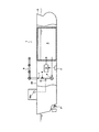
図1は、本発明に係るバラスト処理水供給船の一例を一部切欠して示す側面図である。 FIG. 1 is a side view showing a part of an example of a ballast treated water supply ship according to the present invention.
このバラスト処理水供給船1の船体2内部には、船底付近に設けられたシーチェスト3から取水されたバラスト水を処理する処理装置4と、該処理装置4によって処理されたバラスト水を貯留する貯留タンク5が設けられている。なお、21は航行用のスクリューである。
Inside the
ここで、バラスト水には例えば海水、淡水等が用いられ、本発明では海水が好ましく使用される。かかるバラスト水には、取水した水域に生息する動物プランクトン、植物プランクトン、微生物等の水生生物や大腸菌等の細菌類を含んでいる。 Here, seawater, fresh water, etc. are used for ballast water, and seawater is preferably used in the present invention. Such ballast water includes zooplankton, phytoplankton, aquatic organisms such as microorganisms and bacteria such as Escherichia coli that inhabit the taken water area.
処理装置4は、シーチェスト3から取水されたバラスト水中の水生生物や細菌類を、条約を満足する程度に殺滅可能であればよく、例えば熱、超音波、紫外線、銀イオン、電気等を用いた物理的処理法、濾過、剪断力、キャビテーション等を用いた機械的処理法、オゾン、酸素除去、塩素等を用いた化学的処理法、これらの2種以上の処理法を複合させた複合処理法等が挙げられる。
The
本発明において好ましい処理装置4の一例について図2を用いて説明するが、処理装置4は何ら図示するものに限定されない。
An example of the
図2は処理装置4の一例を示す構成図であり、41はフィルター、42は取水ポンプ、43は処理ライン、44はオゾン混合装置、45はオゾン発生装置、46はスリット板、47は脱気タンク、48は排オゾン分解装置である。
FIG. 2 is a block diagram showing an example of the
取水ポンプ42の作動によりシーチェスト3から処理装置4内にバラスト水が取り込まれ、処理ライン43内を移送される過程で、水生生物や細菌類を殺滅するための処理がなされる。
By the operation of the
フィルター41は、取水ポンプ42の作動によって処理装置4に導入されたバラスト水から夾雑物を取り除くために設けられている。このフィルター41は、後段のオゾン混合装置44によるオゾン注入やスリット板46によって水生生物や細菌類が殺滅処理されることから、水中のゴミ等の比較的大きな夾雑物を取り除ければよい。
The
オゾン混合装置44は、取水ポンプ42の作動によって処理ライン43中を移送されるバラスト水に、オゾン発生装置45によって生成されたオゾンを混入させ、バラスト水中の水生生物や細菌類をオゾンの強酸化作用によって化学的に殺滅する。ここでは、オゾン混合装置44として、処理ライン43中のバラスト水とオゾンとを気液混合する気液混合装置(オゾンインジェクター)を用いた例を示しているが、バラスト水中に所定濃度のオゾンを混入させることができるものであれば特に限定されない。例えば、スタティックミキサー、ラインミキサーなどの静的混合機を使用することもできる。
The
オゾン発生装置45は、例えばコンプレッサー451、酸素発生器452及びオゾン発生器453を有しており、酸素発生器452及びオゾン発生器453を経て生成されたオゾンが、コンプレッサー451によってオゾン供給ライン454を介してオゾン混合装置44に供給され、バラスト水中に所定濃度のオゾンを混入させる。
The
スリット板46は、オゾン混合装置44によってオゾンが混入されたバラスト水を高圧で通過させることにより、その際に発生する剪断力によってバラスト水中の水生生物や細菌類を機械的に破壊して殺滅する。
The
このスリット板46の詳細を図3〜図7に示す。
Details of the
図3は、処理ライン43内のスリット板46を示す断面図、図4は、図3の(iv)−(iv)線断面図であり、これらに示すように、スリット板46は処理ライン43の内部に、該処理ライン43の流路全体を塞ぐようにして配設されている。
3 is a cross-sectional view showing the
スリット板46には複数のスリット状の開口461が形成されている。開口461の開口幅は、バラスト水中の水生生物や細菌類を剪断力によって破壊する効果が充分に発揮され得る幅に設定されるが、好ましくは200μm〜500μmとされる。これにより、バラスト水を通過させる際に発生する剪断現象によって10μm程度の水生生物も殺滅可能である。
A plurality of slit-shaped
処理ライン43内を移送されるバラスト水は、取水ポンプ42の作動によってこのスリット板46に向かって高圧で圧送される。圧送されたバラスト水は乱流状態のままスリット板46のスリット状の開口461を通過しようとし、この開口461を通過する際に剪断現象が生じることで、バラスト水中の水生生物や細菌類を破壊して殺滅する。
Ballast water transferred through the
かかる剪断力による破壊、殺滅効果をより発揮させるために、スリット板46はバラスト水の流れ方向に対して直交する方向に取り付けることが好ましい。
In order to exhibit the effect of destruction and killing due to the shearing force, the
また、スリット板46は、処理ライン43内に密接して取り付けられるが、図示しないが、容易に取り外し可能として洗浄することができるように、フランジ等によって処理ライン43に介設することが好ましい。
In addition, although the
スリット板46に形成される複数のスリット状の開口461の形状は、図4に例示するように、細長い長方形状からなるものが好ましい態様として挙げられる。開口461の本数は特に限定されず、バラスト水の圧力損失、剪断現象の発生状況に応じて適宜設定される。
The shape of the plurality of slit-
なお、各開口461は全て同じ長さに形成してもよいが、図5に示すように、処理ライン43の断面形状に合わせて、中央部を長く、端部に行くほど短く形成してもよい。
Although all the
また、各開口461の形状は直線状に限らず、図6に示すように、円弧状等の曲線状に形成してもよい。
Further, the shape of each
更に、処理ライン43内に配設されるスリット板46の枚数は1枚に限らず、図7に示すように、複数枚(46A、46B)を間隔をおいて配設するようにしてもよい。枚数は複数枚であれば特に限定されない。
Furthermore, the number of
複数枚のスリット板46A、46Bを配設する場合は、各スリット板46A、46Bのそれぞれの開口461の幅、大きさ、本数、形状を異ならせることが好ましい。また、隣接するスリット板46A、46Bのそれぞれの開口461の配置を異ならせ、例えば各スリット板46A、46Bのそれぞれの開口461の長さ方向が直交するように配置させるようにすることも好ましい。これらにより、剪断現象をより一層効果的に発揮させることができ、バラスト水中の水生生物や細菌類の破壊、殺滅効果をより向上させることができる。
When a plurality of
スリット板46を通過した後のバラスト水は脱気タンク47に送られ、バラスト水中の未溶解の余剰オゾンの脱気が行われる。脱気タンク47内には、タンク底部からタンク天井部の手前に亘って立設された仕切り壁471と、タンク天井部からタンク底部の手前に亘って垂設された仕切り壁472とが交互に並設され、バラスト水の上向流路と下向流路とを交互に形成している。これにより、脱気タンク47内に導入されたバラスト水は、上向流路と下向流路とを交互に通過し、その過程で、バラスト水中に気泡状態で混入する余剰オゾンをバラスト水中から除去し、タンク上部の排オゾン室473に溜める。
The ballast water after passing through the
排オゾン室473に溜まった排オゾンは、脱気タンク47から排オゾン分解装置48に送られて分解され、例えばデッキ上から船外に排出される。
Exhaust ozone accumulated in the
このようにして、処理装置4を経たバラスト水は、水生生物や細菌類が所定値以下となるように殺滅されたクリーンなバラスト水(バラスト処理水)となる。
In this way, the ballast water that has passed through the
なお、図2に示す態様では、オゾン混合装置44によりバラスト水中にオゾンを混入させた後にスリット板46を通過させて処理するようにしたが、これに限定されず、スリット板46を通過させた後のバラスト水にオゾン混合装置44によってオゾンを混入させて処理するように構成してもよい。
In the embodiment shown in FIG. 2, ozone is mixed in the ballast water by the
かかる処理装置4を通過することにより処理されたバラスト処理水は貯留タンク5に送られ、該貯留タンク5内に貯留される。貯留されるバラスト処理水は、脱気タンク47によって余剰オゾンが除去されているため、タンクを腐食する問題はない。
Ballast water treated by passing through the
貯留タンク5内に貯留されたバラスト処理水は、港に停泊しているコンテナ船等の船舶(供給対象船舶)のバラストタンクに注水するために供給される。このため、船体1内には、貯留タンク5内からバラスト処理水を取水して供給対象船舶に供給するための供給ポンプ6が設けられており、該供給ポンプ6の作動によって処理水供給ライン7を介して供給されるようになっている。処理水供給ライン7の一端はデッキ22上に引き延ばされて処理水供給管8を形成しており、貯留タンク5内のバラスト処理水をデッキ22上から供給対象船舶へ供給可能としている。
Ballast treated water stored in the storage tank 5 is supplied to inject water into a ballast tank of a ship (supply target ship) such as a container ship anchored at a port. For this reason, a supply pump 6 is provided in the hull 1 to take in the ballast treated water from the storage tank 5 and supply it to the ship to be supplied, and the treated
処理水供給ライン7には、流量調整弁9と流量計10とが設けられている。
The treated
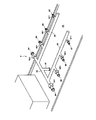
図8は、処理水供給管8の詳細を示す斜視図である。
FIG. 8 is a perspective view showing details of the treated
処理水供給管8は、船体2内の処理水供給ライン7に繋がり、デッキ22上に立設される立上り配管81と、該立上り配管81の上端から船体2の右舷側及び左舷側にそれぞれ向かってデッキ22上を横断するように分岐された横配管82と、該横配管82の両端近傍からそれぞれ分岐され、船首側に向かって平行に延びる2本の縦配管83とを有している。
The treated
横配管82の両端及び各縦配管83の中途部には、それぞれ船体2の右舷側及び左舷側に向かって開口するホース接続口84〜87が設けられている。各ホース接続口84〜87は、それぞれ開閉弁841〜871によって開閉される。
ホース接続口84〜87は全て同一径ではなく、径が異なるものを含んでいる。ここでは、ホース接続口84からホース接続口87に行くに従って径が次第に小さくなり、それが右舷側と左舷側とで左右対称となるように配置されている。このため、複数種の口径のホースの接続部と接続可能である。また、右舷側と左舷側とで左右対称となるように配置されているため、バラスト処理水供給船1の右舷側及び左舷側のいずれの側においても複数種の口径のホースの接続部と接続可能である。しかし、右舷側及び左舷側の全てのホース接続口84〜87の径を異ならせてもよい。また、ホース接続口は右舷側と左舷側とで
異なる配設数としてもよい。
The
供給対象船舶側のホースの接続部が様々な構造を有している場合には、処理水供給管8に設けられる複数のホース接続口は、該船舶側のホースの接続部の構造に対応させて、それぞれ接続部の構造を異ならせるようにしてもよい。
When the connection part of the hose on the supply target ship side has various structures, the plurality of hose connection ports provided in the treated
また、処理水供給管8には、径の異なる複数のホース接続口と接続部の構造の異なる複数のホース接続口とを設け、様々な径及び様々な構造のホースの接続部にも対応できるように構成してもよい。
In addition, the treated
かかるバラスト処理水供給船1によって供給対象船舶にバラスト処理水を供給する様子を図9に示す。 FIG. 9 shows a state in which the ballast treated water is supplied to the supply target ship by the ballast treated water supply ship 1.
クリーンなバラスト水を必要とする供給対象船舶100にバラスト処理水供給船1を横付けした後、バラスト処理水供給船1の処理水供給管8に設けられたいずれかのホース接続口に、供給対象船舶100側から延びる取水用ホース101を接続する。
After laying the ballast treated water supply ship 1 on the
供給対象船舶100には、船体102に取水用ホース101を有する取水管103を設けておき、この取水管103を船体102内部に設けられた副注水ライン104によって、シーチェスト105からバラスト水を取水する既設の主注水ライン106と接続し、該主注水ライン106に設けられているバラストポンプ107の作動によってバラストタンク(図示せず)にバラスト処理水供給船1からのバラスト処理水が注水されるようになっている。
In the
バラスト処理水供給船1から供給対象船舶100へのバラスト処理水の供給は、図1に示すように、処理水供給ライン7に設けられた流量調整弁9によって供給量が調整される。
The supply amount of ballast treated water from the ballast treated water supply ship 1 to the
バラスト水をシーチェスト105から注水するかバラスト処理水供給船1から供給されるようにするかといった供給対象船舶100におけるバラスト水の注水元の選択は、主注水ライン106に設けた開閉弁108と副注水ライン104に設けた開閉弁109の選択的な開閉制御によって行われる。
Selection of the ballast water injection source in the
このように、バラスト処理水供給船1によって供給対象船舶100のバラストタンク内にクリーンなバラスト水を注水することができるので、供給対象船舶100は取水用ホース101を有する取水管103を設け、これを開閉弁108、109を介して既設の主注水ライン106と接続するだけで、新たに処理装置を組み込む場合のような大掛かりな改修工事を不要にできる。
As described above, since the ballast water can be poured into the ballast tank of the
処理水供給ライン7には、図1に示すように、流量計10が設けられており、供給したバラスト処理水の流量を測ることができる。バラスト水供給船1の例えば操舵室内には、図1に示すように、この流量計10の計測結果に基づいて積算流量や供給完了予想時間等の情報を表示する表示部10aが設けられている。
As shown in FIG. 1, the treated
従って、供給対象船舶100に対して必要な量のバラスト処理水を供給することができ、その情報を表示部10aによって確認することができる。更に、この流量計10の計測結果に応じて課金することも可能となる。このような課金情報も表示部10aに表示される。
Accordingly, a necessary amount of ballast water can be supplied to the
以上の態様では、処理装置4によって処理されたバラスト処理水を貯留タンク5に貯留しておき、この貯留タンク5内のバラスト処理水を供給対象船舶100に対して供給するようにした。この態様によれば、バラスト処理水を生成して貯留しておくことができるので、例えば供給対象船舶100の寄港時間や荷役作業等のスケジュールに合わせて、バラスト処理水を予め生成して用意しておき、必要な時に速やかに供給することができる。
In the above aspect, the ballast treated water treated by the
また、供給されるバラスト処理水が、条約を満足する程度に水生生物や細菌類が殺滅されたクリーンなバラスト処理水であるのかどうかを、貯留タンク5内のバラスト処理水をサンプリングすることにより事前に検査して確認しておくことも可能となる。従って、水生生物や細菌類が所定値以下となるように殺滅されたクリーンなバラスト処理水であることをサンプリング結果に基づいて供給対象船舶100に対して提示することができ、安全で安心なバラスト処理水を提供することができる。
In addition, by sampling the ballast treated water in the storage tank 5 to determine whether the supplied ballast treated water is clean ballast treated water in which aquatic organisms and bacteria have been killed to the extent that the convention is satisfied. It is also possible to check and confirm in advance. Therefore, it can be shown to the
また仮に、処理装置4による処理能力、すなわち処理装置4を経て生成されるバラスト処理水の生成量が、供給対象船舶100のバラストポンプ107の取水能力よりも小さい場合でも、予め生成して貯留しておいた貯留タンク5内のバラスト処理水を供給することにより、供給対象船舶100のバラストポンプ107の取水能力に応じた供給量でバラスト処理水を供給することができる利点がある。
Further, even if the processing capacity of the
しかし、本発明はこのように貯留タンク5を有するものに限定されず、図10に示すバラスト処理水供給船11のように必ずしも貯留タンクはなくてもよい。この場合、バラスト処理水供給船11は、処理装置4から排出されるバラスト処理水を、そのまま処理水供給管8から供給対象船舶100に供給する態様とすることができる。図10において図1と同一符号は同一構成を示しているので、ここでの詳細な説明は省略する。
However, the present invention is not limited to the one having the storage tank 5 as described above, and the storage tank may not necessarily be provided like the ballast treated
この態様によれば、バラスト処理水供給船11は、内部にバラスト処理水を貯留する必要がないため、処理装置4、供給ポンプ6、処理水供給ライン7及び処理水供給管8を設置し得る程度の規模の船で足り、貯留タンクを有する場合に比べてコンパクトな船とすることができ、狭い港湾において機動性の高いバラスト処理水供給船を提供できる利点がある。
According to this aspect, since the ballast treated
このような貯留タンクを持たないバラスト処理水供給船11の場合、処理装置4によって処理された後のバラスト処理水をサンプリングして水生生物や細菌類の生存数を検査することにより処理効果を確認するための検査システムを設けておき、検査済みのバラスト処理水を供給対象船舶100に供給できるようにすることが好ましい。
In the case of the ballast treated
なお、バラスト処理水供給船1、11のいずれにおいても、処理装置4、供給ポンプ6、処理水供給ライン7はデッキ22上に設置してもよい。
In any of the ballast treated
また、バラスト処理水供給船1、11からのバラスト処理水の供給は、供給対象船舶側から延びたホースを処理水供給管8に接続する態様に限らない。例えば、図示しないが、バラスト処理水供給船1、11が有する処理水供給管8の構成に代えて、あるいは処理水供給管8の他に、処理水供給ライン7から送られるバラスト処理水を供給対象船舶に供給するためのホースを備え、このホースを供給対象船舶まで延ばして該船舶側の取水口等に接続可能となるように構成してもよい。
Further, the supply of ballast treated water from the ballast treated
更に、処理装置4の他の態様として、水生生物や細菌類を濾過することにより除去可能な例えばMF膜やUF膜等の膜装置を用いることもできる。膜装置の後段に、更に図2に示すようにオゾン混合装置44、オゾン発生装置45及び脱気タンク47を配置してオゾン注入及び余剰オゾンの脱気を行うようにしてもよい。
Furthermore, as another embodiment of the
以上説明したバラスト処理水供給船1、11は、いずれもスクリュー21により自立航行可能な船を例示したが、本発明はこれに限定されない。従って、本発明は自立航行するための機関を持たないバージ船であってもよい。
The ballast treated
1、11:バラスト処理水供給船
2:船体
21:スクリュー
22:デッキ
3:シーチェスト
4:処理装置
41:フィルター
42:取水ポンプ
43:処理ライン
44:オゾン混合装置
45:オゾン発生装置
451:コンプレッサー
452:酸素発生器
453:オゾン発生器
454:オゾン供給ライン
46、46A、46B:スリット板
461:開口
47:脱気タンク
471、472:仕切り壁
473:排オゾン室
48:排オゾン分解装置
5:貯留タンク
6:供給ポンプ
7:処理水供給ライン
8:処理水供給管
81:立上り配管
82:横配管
83:縦配管
84〜87:ホース接続口
841〜871:開閉弁
9:流量調整弁
10:流量計
10a:表示部
DESCRIPTION OF SYMBOLS 1, 11: Ballast treatment water supply ship 2: Hull 21: Screw 22: Deck 3: Sea chest 4: Treatment device 41: Filter 42: Intake pump 43: Treatment line 44: Ozone mixing device 45: Ozone generator 451: Compressor 452: Oxygen generator 453: Ozone generator 454:
Claims (7)
前記処理装置により処理された処理水を供給する供給手段と、
前記処理装置によって処理された後のバラスト処理水をサンプリングして水生生物や細菌類の生存数を検査するための検査システムを備えることを特徴とするバラスト処理水供給船。 A storage tank for storing the treated water treated by the treatment device, comprising: water intake means for taking in the ballast water; and a treatment device for killing aquatic organisms and bacteria in the ballast water taken by the water intake means. There is no ballast treatment water supply ship
Supply means for supplying treated water treated by the treatment device;
A ballast-treated water supply ship comprising an inspection system for sampling the ballast-treated water after being treated by the treatment device and examining the survival number of aquatic organisms and bacteria.
Priority Applications (1)
| Application Number | Priority Date | Filing Date | Title |
|---|---|---|---|
| JP2009178972A JP5021700B2 (en) | 2009-07-31 | 2009-07-31 | Ballast treated water supply ship |
Applications Claiming Priority (1)
| Application Number | Priority Date | Filing Date | Title |
|---|---|---|---|
| JP2009178972A JP5021700B2 (en) | 2009-07-31 | 2009-07-31 | Ballast treated water supply ship |
Related Parent Applications (1)
| Application Number | Title | Priority Date | Filing Date |
|---|---|---|---|
| JP2007023970A Division JP4384184B2 (en) | 2007-02-02 | 2007-02-02 | Ballast treated water supply ship |
Publications (2)
| Publication Number | Publication Date |
|---|---|
| JP2010013098A true JP2010013098A (en) | 2010-01-21 |
| JP5021700B2 JP5021700B2 (en) | 2012-09-12 |
Family
ID=41699604
Family Applications (1)
| Application Number | Title | Priority Date | Filing Date |
|---|---|---|---|
| JP2009178972A Expired - Fee Related JP5021700B2 (en) | 2009-07-31 | 2009-07-31 | Ballast treated water supply ship |
Country Status (1)
| Country | Link |
|---|---|
| JP (1) | JP5021700B2 (en) |
Cited By (5)
| Publication number | Priority date | Publication date | Assignee | Title |
|---|---|---|---|---|
| KR101358323B1 (en) * | 2012-03-07 | 2014-02-05 | 삼성중공업 주식회사 | Ship including ballast water treatment system |
| KR101390493B1 (en) * | 2012-12-26 | 2014-04-30 | 삼성중공업 주식회사 | Vessel for treatment of ballast water |
| JP2015533723A (en) * | 2012-10-23 | 2015-11-26 | ソンポー インダストリイズ カンパニー リミテッドSunbo Industries Co.,Ltd | Ship ballast water treatment system |
| US9212073B2 (en) | 2011-11-04 | 2015-12-15 | Kurita Water Industries Ltd. | Ballast water treatment agent and method of treating ballast water of ship using the same |
| JP2016502476A (en) * | 2012-10-23 | 2016-01-28 | ソンポー インダストリイズ カンパニー リミテッドSunbo Industries Co.,Ltd | Ship ballast water treatment system |
Citations (5)
| Publication number | Priority date | Publication date | Assignee | Title |
|---|---|---|---|---|
| JP2005319975A (en) * | 2004-05-11 | 2005-11-17 | Takao Ushiyama | Connecting method and connecting device of vessel ballast water washing device |
| JP2005324120A (en) * | 2004-05-14 | 2005-11-24 | Jfe Engineering Kk | Ballast water treatment method and apparatus, and float structure having ballast water treatment function |
| JP2006102283A (en) * | 2004-10-07 | 2006-04-20 | Ipb:Kk | Method for processing ship balast water and method for manufacturing sterilized liquid |
| JP2006212492A (en) * | 2005-02-01 | 2006-08-17 | Mitsui Eng & Shipbuild Co Ltd | Method for removing residual ozone in water and method for removing residual ozone in ballast water |
| JP2006314902A (en) * | 2005-05-11 | 2006-11-24 | Nippon Kainan Boshi Kyokai | Ship ballast water treatment device |
-
2009
- 2009-07-31 JP JP2009178972A patent/JP5021700B2/en not_active Expired - Fee Related
Patent Citations (5)
| Publication number | Priority date | Publication date | Assignee | Title |
|---|---|---|---|---|
| JP2005319975A (en) * | 2004-05-11 | 2005-11-17 | Takao Ushiyama | Connecting method and connecting device of vessel ballast water washing device |
| JP2005324120A (en) * | 2004-05-14 | 2005-11-24 | Jfe Engineering Kk | Ballast water treatment method and apparatus, and float structure having ballast water treatment function |
| JP2006102283A (en) * | 2004-10-07 | 2006-04-20 | Ipb:Kk | Method for processing ship balast water and method for manufacturing sterilized liquid |
| JP2006212492A (en) * | 2005-02-01 | 2006-08-17 | Mitsui Eng & Shipbuild Co Ltd | Method for removing residual ozone in water and method for removing residual ozone in ballast water |
| JP2006314902A (en) * | 2005-05-11 | 2006-11-24 | Nippon Kainan Boshi Kyokai | Ship ballast water treatment device |
Cited By (5)
| Publication number | Priority date | Publication date | Assignee | Title |
|---|---|---|---|---|
| US9212073B2 (en) | 2011-11-04 | 2015-12-15 | Kurita Water Industries Ltd. | Ballast water treatment agent and method of treating ballast water of ship using the same |
| KR101358323B1 (en) * | 2012-03-07 | 2014-02-05 | 삼성중공업 주식회사 | Ship including ballast water treatment system |
| JP2015533723A (en) * | 2012-10-23 | 2015-11-26 | ソンポー インダストリイズ カンパニー リミテッドSunbo Industries Co.,Ltd | Ship ballast water treatment system |
| JP2016502476A (en) * | 2012-10-23 | 2016-01-28 | ソンポー インダストリイズ カンパニー リミテッドSunbo Industries Co.,Ltd | Ship ballast water treatment system |
| KR101390493B1 (en) * | 2012-12-26 | 2014-04-30 | 삼성중공업 주식회사 | Vessel for treatment of ballast water |
Also Published As
| Publication number | Publication date |
|---|---|
| JP5021700B2 (en) | 2012-09-12 |
Similar Documents
| Publication | Publication Date | Title |
|---|---|---|
| JP4384184B2 (en) | Ballast treated water supply ship | |
| KR101066674B1 (en) | Electrolysis unit, apparatus for treatment of ballast water of ship with the same | |
| JP4272669B2 (en) | Ship ballast water treatment equipment | |
| US9061925B2 (en) | Liquid treatment methods and apparatus | |
| JP5386690B2 (en) | Liquid detoxification treatment apparatus and ship equipped with this apparatus | |
| JP5562186B2 (en) | Circulation system for ship ballast water | |
| JP5292474B2 (en) | Antifouling system using ballast water and control method thereof | |
| JP5021700B2 (en) | Ballast treated water supply ship | |
| KR20100017410A (en) | Water treatment system | |
| JP4877281B2 (en) | Ballast water treatment apparatus and ballast water treatment method | |
| JP5173544B2 (en) | Ballast water treatment ship and untreated ballast water treatment method | |
| JP4737157B2 (en) | Ballast water treatment apparatus and ballast water treatment method | |
| JP4303758B2 (en) | Ballast treated water supply ship and ballast treated water supply method | |
| JP2008189071A (en) | Ballast treated water supply device and ballast treated water supply ship | |
| JP2008195114A (en) | Mooring device, ship, and ballast processing water supply ship | |
| JP4885829B2 (en) | Ozone mixer | |
| JP4384061B2 (en) | Ballast water circulation device | |
| KR101050396B1 (en) | Device for injecting ozone into ballast water for a ship | |
| KR101656529B1 (en) | Advanced electrolysis system using ultrasonic effects as enhancement equipments for ballast water treatment | |
| KR101590793B1 (en) | Apparatus for supplying salt water and system for treating ballast water having the same | |
| KR20140020817A (en) | Ship and ballast water treatment system | |
| KR101163344B1 (en) | A Method for Treatment of Ballast Water of Ship Using Electrolysis Unit | |
| JP2009112908A (en) | Method of backwashing membrane filtration device | |
| JP2009006213A (en) | Cleaning method of membrane filtration device | |
| AU2012203894B2 (en) | Ballast water treatment methods and apparatus |
Legal Events
| Date | Code | Title | Description |
|---|---|---|---|
| A621 | Written request for application examination |
Free format text: JAPANESE INTERMEDIATE CODE: A621 Effective date: 20100125 |
|
| A977 | Report on retrieval |
Free format text: JAPANESE INTERMEDIATE CODE: A971007 Effective date: 20110926 |
|
| A131 | Notification of reasons for refusal |
Free format text: JAPANESE INTERMEDIATE CODE: A131 Effective date: 20111004 |
|
| A521 | Written amendment |
Free format text: JAPANESE INTERMEDIATE CODE: A523 Effective date: 20111130 |
|
| TRDD | Decision of grant or rejection written | ||
| A01 | Written decision to grant a patent or to grant a registration (utility model) |
Free format text: JAPANESE INTERMEDIATE CODE: A01 Effective date: 20120522 |
|
| A01 | Written decision to grant a patent or to grant a registration (utility model) |
Free format text: JAPANESE INTERMEDIATE CODE: A01 |
|
| A61 | First payment of annual fees (during grant procedure) |
Free format text: JAPANESE INTERMEDIATE CODE: A61 Effective date: 20120614 |
|
| R150 | Certificate of patent or registration of utility model |
Ref document number: 5021700 Country of ref document: JP Free format text: JAPANESE INTERMEDIATE CODE: R150 Free format text: JAPANESE INTERMEDIATE CODE: R150 |
|
| FPAY | Renewal fee payment (event date is renewal date of database) |
Free format text: PAYMENT UNTIL: 20150622 Year of fee payment: 3 |
|
| S111 | Request for change of ownership or part of ownership |
Free format text: JAPANESE INTERMEDIATE CODE: R313111 |
|
| S533 | Written request for registration of change of name |
Free format text: JAPANESE INTERMEDIATE CODE: R313533 |
|
| R350 | Written notification of registration of transfer |
Free format text: JAPANESE INTERMEDIATE CODE: R350 |
|
| LAPS | Cancellation because of no payment of annual fees |