JP2010012376A - Pipette calibration apparatus and pipette calibration device using the same - Google Patents
Pipette calibration apparatus and pipette calibration device using the same Download PDFInfo
- Publication number
- JP2010012376A JP2010012376A JP2008172360A JP2008172360A JP2010012376A JP 2010012376 A JP2010012376 A JP 2010012376A JP 2008172360 A JP2008172360 A JP 2008172360A JP 2008172360 A JP2008172360 A JP 2008172360A JP 2010012376 A JP2010012376 A JP 2010012376A
- Authority
- JP
- Japan
- Prior art keywords
- pipette
- container
- humidity
- measurement container
- sensor
- Prior art date
- Legal status (The legal status is an assumption and is not a legal conclusion. Google has not performed a legal analysis and makes no representation as to the accuracy of the status listed.)
- Granted
Links
Images


Abstract
Description
この発明は、微小容量の液体を計量するピペットの校正用機器および同機器を用いるピペット校正用装置に関するものである。 The present invention relates to a pipette calibration device for measuring a minute volume of liquid and a pipette calibration device using the same.
微小容量を計量する機器として、手動ないしは電動方式のピペットが知られており、主として、バイオ、製薬などの分野での液体素材の測定に使用され、測定精度の向上と計量品質の証明責任がより重要視されている。 Manual or electric pipettes are known as devices for measuring minute volumes, and are mainly used for measuring liquid materials in fields such as biotechnology and pharmaceuticals. It is important.
この種のピペットの校正には、質量計として天びんが利用され、校正管理用の媒体としては、純水が使用されており、容量の確定に水の質量を計量する手法が確立されている。 For this type of pipette calibration, a balance is used as a mass meter, pure water is used as a calibration management medium, and a method for measuring the mass of water to determine the capacity has been established.
このうち、特に、マイクロピペットと呼ばれている1μL=1mg以下の微小量を確定する際には、水の蒸発量をコントロールする必要があり、雰囲気湿度を高湿一定とするために、湿度保持容器と呼ばれる専用機器が用意されており、例えば、特許文献1にその機器が開示されている。 Among these, in particular, when determining a minute amount of 1 μL = 1 mg or less, which is called a micropipette, it is necessary to control the evaporation amount of water, and in order to keep the atmospheric humidity constant, the humidity is maintained. A dedicated device called a container is prepared. For example, Patent Document 1 discloses the device.
特許文献1に開示されている専用機器は、二重構造の内および外容器を備え、中心部にピペットの先端側が挿入可能な垂直状の貫通孔が設けられている。貫通孔内には、質量を測定する測定容器が配置され、この測定容器内にピペットから、例えば、純水が滴下される。 The dedicated device disclosed in Patent Document 1 includes inner and outer containers having a double structure, and a vertical through-hole into which a tip end of a pipette can be inserted is provided at the center. A measurement container for measuring mass is disposed in the through hole, and pure water, for example, is dropped from the pipette into the measurement container.
測定容器の下端は、質量を測定するための天びんの質量センサに連結されている。内容器は、貫通孔側が通気性を有していて、内部に吸湿剤が充填されている。このように構成された湿度保持容器によれば、内容器内に充填された吸湿剤により、貫通孔内が所定の湿度状態に保たれるので、正確な校正が行えるとされている。 The lower end of the measuring container is connected to a balance mass sensor for measuring mass. The inner container has air permeability on the through hole side and is filled with a hygroscopic agent. According to the humidity holding container configured as described above, the inside of the through hole is maintained in a predetermined humidity state by the hygroscopic agent filled in the inner container, so that accurate calibration can be performed.
しかしながら、このような従来のピペット校正用専用機器には、以下に説明する技術的な課題があった。 However, such a conventional dedicated pipette calibration device has the following technical problems.
特許文献1に開示されているピペット校正用専用機器では、ピペットの先端側を挿入する貫通孔は、外容器の上端に開口しているが、測定容器に純水を滴下する操作性に課題があった。 In the pipette calibration dedicated device disclosed in Patent Document 1, the through hole for inserting the tip side of the pipette opens at the upper end of the outer container, but there is a problem in the operability of dropping pure water into the measurement container. there were.
すなわち、この種の専用機器が使用される天びんは、その殆ど全てに風防が構造上不可欠となっており、専用機器は、風防内に設置されることになるが、風防は、通常、その上面が天びんの設置面から30cm程度上方に位置している。 In other words, almost all balances that use this type of special equipment have an indispensable structure for the windshield, and the special equipment is installed in the windshield. Is located approximately 30 cm above the balance installation surface.
一方、ピペットは、これを手で掴む位置から先端まで約15cm程度の長さしかないので、実際に、風防の上方から、モイスチャトラップ内に配置されている測定容器に、純水を正確に滴下するには、かなりの困難性を伴う。 On the other hand, since the pipette is only about 15 cm long from the position where it is grasped by hand to the tip, actually, pure water is accurately dripped from above the draft shield into the measuring vessel placed in the moisture trap. It involves considerable difficulty.
この困難性は、より具体的には、例えば、操作者が座った状態から、肘と手首への無理な角度設定を強いること、および、測定容器とピペット先端の距離が離れていることに起因して、的外れの操作を防ぐために必要となる、著しい注意力とを要求されることを意味している。 More specifically, this difficulty is caused by, for example, forcing an unreasonable angle setting on the elbow and wrist from the state where the operator is sitting, and that the distance between the measurement container and the pipette tip is large. This means that a great deal of attention is required to prevent unintentional operations.
また、上述した専用機器を含めて、市販されているピペット校正機器には、専用機器と各種の測定値補正用ソフトウエアが付属しているが、例えば、湿度センサ等の環境測定機器は、付属されておらず、特に、トラップ内の湿度は、測定されていないので、校正精度の確保に欠けるという問題もあった。 In addition, commercially available pipette calibration instruments, including the dedicated instruments described above, come with dedicated instruments and various measurement value correction software. For example, environmental measuring instruments such as humidity sensors are included. In particular, since the humidity in the trap has not been measured, there has been a problem that the accuracy of calibration is insufficient.
本発明は、このような従来の問題点に鑑みてなされたものであって、その目的とするところは、校正の操作性を改善し、かつ、測定精度の向上も可能になるピペット校正用機器および同機器を用いるピペット校正用装置を提供することにある。 The present invention has been made in view of such conventional problems, and the object of the present invention is to improve the operability of calibration and improve the measurement accuracy. And providing a pipette calibration apparatus using the same device.
上記目的を達成するために、本発明は、ピペットで滴下する液体を受承する測定容器と、前記測定容器の質量を計量する質量センサとを有するピペット校正用器具において、前記測定容器を内部に収容する湿度保持容器と、前記測定容器が設置されている雰囲気の湿度を測定する湿度センサとを有し、前記湿度保持容器は、分離可能に結合される本体部と蓋部とを備え、前記本体部は、中心軸上に配置される前記測定容器の外周を囲繞するように設けられ、上端が開放した加湿用の環状水溜め部を有し、前記蓋部は、上端面と、当該上端面に連なる傾斜面とを有し、前記傾斜面には、前記ピペットの挿入用貫通窓を設けた。 In order to achieve the above object, the present invention provides a pipette calibration instrument having a measurement container for receiving a liquid dropped by a pipette and a mass sensor for measuring the mass of the measurement container. A humidity holding container for housing and a humidity sensor for measuring the humidity of the atmosphere in which the measurement container is installed, the humidity holding container including a main body portion and a lid portion that are detachably coupled, The main body portion is provided so as to surround the outer periphery of the measurement container disposed on the central axis, and has a humidified annular water reservoir portion having an open upper end. The lid portion includes an upper end surface and the upper surface. And an through-hole for inserting the pipette is provided on the inclined surface.
このように構成したピペット校正用機器によれば、湿度保持容器は、分離可能に結合される本体部と蓋部とを備え、本体部は、中心軸上に配置される測定容器の外周を囲繞するように設けられ、上端が開放した加湿用の環状水溜め部を有し、蓋部は、上端面と、当該上端面に連なる傾斜面とを有し、傾斜面には、ピペットの挿入用貫通窓を設けているので、これを風防が設けられている天びんに設置しても、傾斜面の側方からのピペット操作が可能になり、的確に液体を測定容器に滴下することができ、操作性が大きく改善される。 According to the pipette calibration apparatus configured as described above, the humidity holding container includes a main body portion and a lid portion that are detachably coupled, and the main body portion surrounds the outer periphery of the measurement container disposed on the central axis. The lid has an upper end surface and an inclined surface connected to the upper end surface, and the inclined surface is used for inserting a pipette. Since a through window is provided, even if this is installed on a balance equipped with a windshield, pipetting from the side of the inclined surface is possible, and liquid can be accurately dropped into the measurement container, The operability is greatly improved.
また、湿度センサを有しているので、例えば、湿度が飽和した状態での校正や、特定湿度での校正が可能になり、滴下される純水などの蒸発を防ぎ、正確な容量決定が可能になる。 In addition, since it has a humidity sensor, it can be calibrated when the humidity is saturated, or calibrated at a specific humidity, preventing evaporation of pure water dripping, etc., and allowing accurate volume determination. become.
前記湿度センサは、前記湿度保持容器内に配置することができる。前記湿度センサは、前記湿度保持容器の上端面に配置することができる。 The humidity sensor can be disposed in the humidity holding container. The humidity sensor can be disposed on an upper end surface of the humidity holding container.
前記測定容器は、測定可能な最大質量が異なる複数種類を備え、前記質量センサとの結合は、共通の容器ホルダーを介装して行うことができる。 また、本発明は、ピペットで滴下する液体を受承する測定容器と、前記測定容器の質量を計量する質量センサとを有するピペット校正用装置において、前記測定容器を内部に収容する湿度保持容器と、前記測定容器が設置されている雰囲気の湿度を測定する湿度センサと、前記液体の温度を測定する温度センサと、気温計,気圧計と、演算制御器とを有し、前記湿度保持容器は、分離可能に結合される本体部と蓋部とを備え、前記本体部は、中心軸上に配置される前記測定容器の外周を囲繞するように設けられ、上端が開放した加湿用の環状水溜め部を有し、前記蓋部は、上端面と、当該上端面に連なる傾斜面とを有し、前記上端面には、前記湿度センサを設置するとともに、前記傾斜面には、前記ピペットの挿入用貫通窓を設け、前記演算制御器は、前記湿度センサ,水温センサ,気圧計,気温計の検出値に基づいて、前記質量センサの検出値を補正するようにした。 The measurement containers include a plurality of types having different maximum measurable masses, and can be coupled to the mass sensor through a common container holder. Further, the present invention provides a pipette calibration apparatus having a measurement container that receives a liquid dropped by a pipette and a mass sensor that measures the mass of the measurement container; a humidity holding container that houses the measurement container; A humidity sensor that measures the humidity of the atmosphere in which the measurement container is installed, a temperature sensor that measures the temperature of the liquid, a thermometer, a barometer, and an arithmetic controller, A body portion and a lid portion that are detachably coupled, and the body portion is provided so as to surround an outer periphery of the measurement container disposed on a central axis, and is a humidified annular water having an open upper end. A reservoir portion, the lid portion having an upper end surface and an inclined surface connected to the upper end surface; the humidity sensor is installed on the upper end surface; and the pipette is provided on the inclined surface. An insertion through-hole is provided to perform the calculation Your vessel, the humidity sensor, the water temperature sensor, a barometer, based on a value detected by the temperature meter, and to correct the detected value of the mass sensor.
このように構成したピペット校正用装置によれば、演算制御器は、湿度センサ,水温センサ,気温計,気圧計の検出値に基づいて、質量センサの検出値を補正するので、ピペットの校正作業の操作性の改善効果に加えて、校正精度をより一層向上させることができる。 According to the pipette calibration apparatus configured as described above, the arithmetic controller corrects the detection value of the mass sensor based on the detection values of the humidity sensor, water temperature sensor, thermometer, and barometer. In addition to the operability improvement effect, the calibration accuracy can be further improved.
本発明にかかるピペット校正用機器および同機器を用いるピペット校正装置によれば、校正の操作性を改善し、かつ、測定精度の向上も可能になる。 According to the pipette calibration apparatus and the pipette calibration apparatus using the apparatus according to the present invention, the operability of calibration can be improved and the measurement accuracy can be improved.
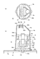
以下、本発明の好適な実施の形態について、添付図面に基づいて詳細に説明する。図1は、本発明に係るピペット校正用機器の一実施例を示している。同図に示したピペット校正用機器10は、測定容器12と、質量センサ14と、湿度保持容器16と、湿度センサ18とを備えている。測定容器12は、校正しようとするピペットから滴下される液体、例えば、純水を受承するたのものである。
DESCRIPTION OF EXEMPLARY EMBODIMENTS Hereinafter, preferred embodiments of the invention will be described in detail with reference to the accompanying drawings. FIG. 1 shows an embodiment of a pipette calibration device according to the present invention. The
質量センサ14は、測定容器12の質量を測定するものであって、例えば、分析用精密天びんから構成される。湿度保持容器16は、測定容器12を内部に収容し、測定容器12の計量媒体である純水の蒸発を防ぎ、蒸発により発生する計量誤差要因を低減させるものであって、本実施例の場合、例えば、透明な合成樹脂で形成された本体部16aおよび蓋部16bと、金属製の台部16cとを有している。
The
台部16cは、円盤状に形成され、中心には、貫通孔160cが穿設され、この貫通孔160cは、後述する測定容器12の突部122bの挿通が可能な大きさになっている。
The
本体部16aは、中心軸上に測定容器12が配置され、測定容器の外周を囲繞するように、上下端が開口した概略円筒状に形成されている。蓋部16bは、上端が閉塞したカップ状に形成されている。本体部16aの下開口160aには、円盤状の台部16cが嵌合され、台部16cは、質量センサ14の床面14aに載置される。
The
本体部16aの上開口161aには、蓋部16bの下端開口160bが着脱自在に嵌合されている。本体部16aの上端側の内周面には、環状の棚部162aが設けられ、この棚部162aで囲繞されて上端が開口した環状空間部が水溜め部16dとなっている。
A lower end opening 160b of the
蓋部16bは、平坦な上端面161bと、この上端面に連なり、下方に所定の角度で傾斜する傾斜面162bとを備え、上端面161bには、内方に陥没する凹部163bが形成され、この凹部163b内には、湿度センサ18が配置されている。凹部163b内に設置された湿度センサ18は、測定容器12の上方に位置している。
The
また、傾斜面162bには、ピペットの先端側を挿入するための貫通窓16eが穿設されている。湿度センサ18は、本体部18aと、本体部18aを保持するホルダ18bとから構成され、凹部163b内に着脱可能に挿入されている。
The
一方、測定容器12は、本体部16aの中心軸上に配置され、測定容器本体12aと、容器ホルダ12bとを備えており、本実施例の場合には、測定容器本体12aは、測定可能な最大質量が、5mlであって、上端が開口した筒状に形成されている。
On the other hand, the
容器ホルダ12bは、凹状の形成された下ホルダ120bと、下ホルダ120b内に嵌合される上ホルダ121bとを有し、測定容器本体12aの下端が上ホルダ121bの上部に嵌合されている。下ホルダ120bの下面には、質量センサ14との連結に用いられる突部122bが中心軸上に突設されている。
The
突部122bは、先端が先細状に形成され、質量センサ14の荷重受軸14bに嵌合固定される。突部122bを荷重受軸14bに嵌合固定すると、測定容器12は、自立状態になって、荷重が全て質量センサ14に伝達される。
The
以上のように形成されたピペット校正用機器10では、ピペットの容量を校正する際には、水溜め部16d内に水が収容され、ピペットの先端を貫通窓16eから本体部16a内に挿入させて、測定容器本体12a内に、例えば、純水を滴下して、その質量を質量センサ14で測定することにより、校正操作が行われる。
In the
この場合、本実施例のピペット校正用機器10によれば、湿度保持容器16は、分離可能に結合される本体部16aと蓋部16bとを備え、本体部16aは、中心軸上に配置される測定容器12の外周を囲繞するように設けられ、上端が開放した加湿用の環状水溜め部16dを有し、蓋部16bは、上端面161bと、当該上端面161bに連なる傾斜面162bとを有し、傾斜面162bには、ピペットの挿入用貫通窓16eを設けているので、これを風防が設けられている天びんに設置しても、傾斜面162bの側方からのピペット操作が可能になり、適格に液体を測定容器12に滴下することができ、操作性が大きく改善される。
In this case, according to the
この操作性の改善効果についてより具体的に説明すると、ピペットの通常の校正操作方法では、例えば、バイアル瓶などに入った純水などの液体を、ピペットの先端部分に浸漬し、手動また電動操作により、純水を吸上げて、そのまま測定容器12の上面側にもっていき、再び、手動または電動操作により、保持している液体を容器12内に滴下するものとなる。
This operability improvement effect will be explained in more detail. In the normal calibration method for pipettes, for example, a liquid such as pure water in a vial is immersed in the tip of the pipette, and is manually or electrically operated. As a result, the pure water is sucked up and directly brought into the upper surface side of the
これらの実際の操作を想定すると、人の左右の腕は、人の顔の正面を中心として、回転,平行移動などの複雑な動作の組合わせにより、ピペットの校正作業を行っており、ピペットを持つ手の平が、垂直に対して、ある傾斜角度を持つことが自然であることが認識される。 Assuming these actual operations, the left and right arms of the person are calibrating the pipette by a combination of complex movements such as rotation and translation around the front of the person's face. It is recognized that it is natural for the palm of the hand to have a certain tilt angle with respect to the vertical.
これに対して、従来の湿度保持容器では、測定容器に到る角度が垂直になっていたので、操作性に難点があったが、本実施例では、傾斜面162bを設けて、ここに貫通窓16eを配置することで、自然に操作できるようにしたものである。また、蓋部16bには、湿度センサ18が設けられているので、例えば、湿度が飽和した状態での校正や、特定値に湿度を維持した状態での校正が可能になる。
On the other hand, in the conventional humidity holding container, since the angle to the measurement container was vertical, there was a problem in operability. In the present embodiment, an
図2は、本発明に係るピペット校正用機器10aの他の実施例を示しており、上記実施例と同一もしくは相当する部分には、同一符号を付して、その説明を省略するとともに、以下にその特徴点についてのみ説明する。
FIG. 2 shows another embodiment of the
この図に示したピペット校正用機器10aは、測定容器12’の計量容量が上記実施例よりも大きくなっていて、最大質量30mlまで校正できるようになっている。
The
本実施例の場合、測定容器本体12a’は、図1の6倍となっていて、容器ホルダ12bは、上ホルダ121bを除去して、下ホルダ121bだけで構成し、このホルダ121bに測定容器本体12a’が嵌合固定されている。このように構成したピペット校正用機器10aでも上記実施例と同等の作用効果が得られる。
In the case of the present embodiment, the measurement container
図3および図4は、上記構成のピペット校正用機器10を用いるピペット校正装置の一実施例を示している。同図に示したピペット校正装置は、ピペット校正用機器10と、測定容器12と、質量センサ14と、湿度保持容器16と、湿度センサ18と、水温センサ20と、演算制御器22とを備えている。
3 and 4 show an embodiment of a pipette calibration apparatus using the
本実施例の場合にも、湿度保持容器16は、分離可能に結合される本体部16aと蓋部16bとを備え、本体部16aは、中心軸上に配置される測定容器12の外周を囲繞するように設けられ、上端が開放した加湿用の環状水溜め部16dを有し、蓋部16bは、上端面161bと、当該上端面161bに連なる傾斜面162bとを有し、傾斜面162bには、ピペットの挿入用貫通窓16eを設けている。
Also in the case of the present embodiment, the
演算制御器22は、例えば、cpuとメモリなどを備えたマイクロコンピュータから構成され、湿度センサ18,水温センサ20,および、制御器22に内蔵された気圧計,温度計の各検出値に基づいて、質量センサ14の検出値を補正する。
The arithmetic controller 22 is composed of, for example, a microcomputer provided with cpu and a memory, and is based on the
水温センサ20は、校正に用いる純水が収容されている槽24内の、純水の温度測定する。なお、演算制御器22に内蔵されている温度計(気温計)および湿度計や気圧計は、外部に設置する形態のものであってもよい。
The
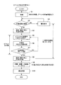
図4は、上記構成のピペット校正装置で行われる校正手順のフロー図である。手順がスタートすると、まず、S1で、準備の確認が行われる。ここでの確認は、校正に用いる純水の準備や、ピペット校正用機器10の水溜め部16d内に所定の水が収容されているか、さらには、校正用のピペットの容量値の確認およびその入力などである。
FIG. 4 is a flowchart of a calibration procedure performed by the pipette calibration apparatus having the above configuration. When the procedure starts, first, preparation is confirmed in S1. The confirmation here is the preparation of pure water used for calibration, whether predetermined water is contained in the
準備が確認されると、S2で、作業環境の確認が行われる。ここでの作業環境とは、環境温度および湿度,気圧であり、例えば、ISOには、ピペットの校正作業を行う環境として、相対湿度50%以上、温度15〜30℃となっているので、これに準拠して確認する。これらの測定値が得られると、S3で、その値が記録される。なお、S2で作業環境の確認が行われない場合、あるいはこれから逸脱している場合には、S4で警告が表示される。 When the preparation is confirmed, the work environment is confirmed in S2. The working environment here is the environmental temperature, humidity, and atmospheric pressure. For example, in ISO, the environment for performing pipette calibration work is a relative humidity of 50% or more and a temperature of 15 to 30 ° C. Confirm in accordance with. Once these measurements are obtained, the values are recorded at S3. If the work environment is not confirmed in S2, or if the work environment is deviated from this, a warning is displayed in S4.
続くS5では、ピペットに槽24内の純水を吸上げて、これを機器10の測定容器12内に滴下する。そして、S6で、質量センサ14の測定値Wiが読み取られる。
In subsequent S <b> 5, the pure water in the
次に、S7で、測定値Wiが必要回数得られたか否かが判断され、必要回数得られていない場合には、S5に戻り、S5〜S7を繰り返すことにより、測定値Wiが必要回数得られたと判断されると、S8に移行する。 Next, in S7, it is determined whether or not the required value Wi has been obtained. If the required value has not been obtained, the process returns to S5 and repeats S5 to S7 to obtain the required value Wi. If it is determined that it has been made, the process proceeds to S8.
S8では、温度、湿度、気圧、水温、および湿度センサ14のその時の各値が記録される。次のS9では、質量から容量への変換演算が行われる。このときの変換式は、Vi=Wi×Zとする。Zは、気圧と純水の密度とを考慮した補正値であって、平均温度と気圧に基づいて予め求めて、チャートとして演算制御器22に記憶されている。
In S8, temperature, humidity, atmospheric pressure, water temperature, and each value of the
次のS10では、S9で求めた質量値Viが適合しているか否かを判断して、手順が終了する。 In the next S10, it is determined whether or not the mass value Vi obtained in S9 is suitable, and the procedure ends.
さて、以上のように校正したピペット校正装置では、ピペット校正機器10を用いるので、操作性が改良されるとともに、温度や湿度に基づいて校正値を補正するので、より一層精度の高いピペット校正を確保することができる。
Now, in the pipette calibration apparatus calibrated as described above, since the
本発明にかかるピペット校正用機器および同機器を用いるピペット校正装置によれば、校正作業における操作性が改善され、かつ、校正精度も向上するので、計量の分野で有効に活用することができる。 According to the pipette calibration apparatus and the pipette calibration apparatus using the apparatus according to the present invention, the operability in the calibration work is improved and the calibration accuracy is improved, so that it can be effectively used in the field of measurement.
10 ピペット校正用機器
12 測定容器
14 質量センサ
16 湿度保持容器
16a 本体部
16b 蓋部
16d 水溜め部
16e 貫通窓
162b 傾斜面
18 湿度センサ
20 水温センサ
22 演算制御器
DESCRIPTION OF
Claims (5)
前記傾斜面には、前記ピペットの挿入用貫通窓を設けたことを特徴とするピペット校正用器具。 In a pipette calibration instrument having a measurement container for receiving liquid dropped by a pipette and a mass sensor for measuring the mass of the measurement container, a humidity holding container for housing the measurement container and the measurement container are installed A humidity sensor for measuring the humidity of the atmosphere, wherein the humidity holding container includes a main body portion and a lid portion that are detachably coupled, and the main body portion is disposed on a central axis. It is provided so as to surround the outer periphery of the measurement container, has an annular water reservoir for humidification with an open upper end, and the lid has an upper end surface and an inclined surface connected to the upper end surface,
An instrument for pipette calibration, wherein the inclined surface is provided with a through-hole for inserting the pipette.
前記質量センサとの結合は、共通の容器ホルダーを介装して行うことを特徴とする請求項1〜3のいずれか1項記載のピペット校正用機器。 The measurement container comprises a plurality of types having different maximum masses that can be measured,
The pipette calibration device according to any one of claims 1 to 3, wherein the coupling with the mass sensor is performed via a common container holder.
前記湿度保持容器は、分離可能に結合される本体部と蓋部とを備え、
前記本体部は、中心軸上に配置される前記測定容器の外周を囲繞するように設けられ、上端が開放した加湿用の環状水溜め部を有し、
前記蓋部は、上端面と、当該上端面に連なる傾斜面とを有し、
前記上端面には、前記湿度センサを設置するとともに、前記傾斜面には、前記ピペットの挿入用貫通窓を設け、
前記演算制御器は、前記湿度センサ,水温センサ,気圧計,気温計の検出値に基づいて、前記質量センサの検出値を補正することを特徴とするピペット校正用装置。 In a pipette calibration apparatus having a measurement container that receives a liquid dropped by a pipette and a mass sensor that measures the mass of the measurement container, a humidity holding container that houses the measurement container, and the measurement container is installed A humidity sensor that measures the humidity of the atmosphere being performed, a temperature sensor that measures the temperature of the liquid, a thermometer, a barometer, and an arithmetic controller;
The humidity holding container includes a body portion and a lid portion that are detachably coupled,
The main body portion is provided so as to surround the outer periphery of the measurement container disposed on the central axis, and has an annular water reservoir for humidification with an open upper end.
The lid portion has an upper end surface and an inclined surface connected to the upper end surface,
The upper end surface is provided with the humidity sensor, and the inclined surface is provided with a through-hole for insertion of the pipette,
2. The pipette calibration apparatus according to claim 1, wherein the arithmetic controller corrects a detection value of the mass sensor based on detection values of the humidity sensor, water temperature sensor, barometer, and thermometer.
Priority Applications (1)
| Application Number | Priority Date | Filing Date | Title |
|---|---|---|---|
| JP2008172360A JP5276369B2 (en) | 2008-07-01 | 2008-07-01 | Pipette calibration equipment and pipette calibration equipment using the equipment |
Applications Claiming Priority (1)
| Application Number | Priority Date | Filing Date | Title |
|---|---|---|---|
| JP2008172360A JP5276369B2 (en) | 2008-07-01 | 2008-07-01 | Pipette calibration equipment and pipette calibration equipment using the equipment |
Publications (2)
| Publication Number | Publication Date |
|---|---|
| JP2010012376A true JP2010012376A (en) | 2010-01-21 |
| JP5276369B2 JP5276369B2 (en) | 2013-08-28 |
Family
ID=41699024
Family Applications (1)
| Application Number | Title | Priority Date | Filing Date |
|---|---|---|---|
| JP2008172360A Active JP5276369B2 (en) | 2008-07-01 | 2008-07-01 | Pipette calibration equipment and pipette calibration equipment using the equipment |
Country Status (1)
| Country | Link |
|---|---|
| JP (1) | JP5276369B2 (en) |
Cited By (2)
| Publication number | Priority date | Publication date | Assignee | Title |
|---|---|---|---|---|
| JP2011528118A (en) * | 2008-07-16 | 2011-11-10 | ビオヒット・ユルキネン・オサケユキテュア | Characterization method and kit for carrying out the method |
| KR20180012389A (en) * | 2016-07-26 | 2018-02-06 | 한국산업기술시험원 | Automatic volume measurement device of glass pipette |
Citations (5)
| Publication number | Priority date | Publication date | Assignee | Title |
|---|---|---|---|---|
| JPH07507135A (en) * | 1992-02-28 | 1995-08-03 | アーテル・インコーポレーテッド | pipette calibration system |
| US6455787B1 (en) * | 1999-11-09 | 2002-09-24 | Tecan Trading Ag | Method for determining the weights of liquid units, weighing insert and weighing arrangement |
| JP2002286591A (en) * | 2001-01-10 | 2002-10-03 | Mettler Toledo Ag | Calibrating apparatus for multi-channel pipette having container transfer device |
| JP2008076393A (en) * | 2006-09-19 | 2008-04-03 | Csem Centre Suisse D'electronique & De Microtechnique Sa | Device and method for calibrating pipette or feed system |
| JP2008292463A (en) * | 2007-03-30 | 2008-12-04 | F Hoffmann La Roche Ag | Device and method for volume measurement by liquid weight measurement and analyzing apparatus containing the device |
-
2008
- 2008-07-01 JP JP2008172360A patent/JP5276369B2/en active Active
Patent Citations (5)
| Publication number | Priority date | Publication date | Assignee | Title |
|---|---|---|---|---|
| JPH07507135A (en) * | 1992-02-28 | 1995-08-03 | アーテル・インコーポレーテッド | pipette calibration system |
| US6455787B1 (en) * | 1999-11-09 | 2002-09-24 | Tecan Trading Ag | Method for determining the weights of liquid units, weighing insert and weighing arrangement |
| JP2002286591A (en) * | 2001-01-10 | 2002-10-03 | Mettler Toledo Ag | Calibrating apparatus for multi-channel pipette having container transfer device |
| JP2008076393A (en) * | 2006-09-19 | 2008-04-03 | Csem Centre Suisse D'electronique & De Microtechnique Sa | Device and method for calibrating pipette or feed system |
| JP2008292463A (en) * | 2007-03-30 | 2008-12-04 | F Hoffmann La Roche Ag | Device and method for volume measurement by liquid weight measurement and analyzing apparatus containing the device |
Cited By (3)
| Publication number | Priority date | Publication date | Assignee | Title |
|---|---|---|---|---|
| JP2011528118A (en) * | 2008-07-16 | 2011-11-10 | ビオヒット・ユルキネン・オサケユキテュア | Characterization method and kit for carrying out the method |
| KR20180012389A (en) * | 2016-07-26 | 2018-02-06 | 한국산업기술시험원 | Automatic volume measurement device of glass pipette |
| KR101864156B1 (en) * | 2016-07-26 | 2018-06-05 | 한국산업기술시험원 | Automatic volume measurement device of glass pipette |
Also Published As
| Publication number | Publication date |
|---|---|
| JP5276369B2 (en) | 2013-08-28 |
Similar Documents
| Publication | Publication Date | Title |
|---|---|---|
| JP5405762B2 (en) | Apparatus and method for volume measurement by weight measurement of liquid and analyzer including this apparatus | |
| US8691074B2 (en) | Method for operating a measuring device having at least one probe, which has at least one ion selective electrode | |
| US4473458A (en) | Ion measuring device with self-contained storage of standardizing solution | |
| JPH01502360A (en) | Method and device for measuring concentration contained in solution | |
| JP5055195B2 (en) | Total alkalinity measurement method in water | |
| JP5400541B2 (en) | Gravimetric method | |
| CN108759733A (en) | With the device and method of gasmetry irregularly shaped object volume | |
| US4314029A (en) | Apparatus for automatically measuring changes in amount of gas | |
| CN103940946B (en) | A kind of gravimetric titrimetry device and titration method with titration protection assembly | |
| JP2018081085A (en) | Receiving container for weight method-like calibration of pipette | |
| JP5276369B2 (en) | Pipette calibration equipment and pipette calibration equipment using the equipment | |
| US9234828B2 (en) | Free floating tilt hydrometer | |
| US6455787B1 (en) | Method for determining the weights of liquid units, weighing insert and weighing arrangement | |
| US11747240B2 (en) | Method and system for preparing a solution | |
| CN209182208U (en) | Glove-type building coating water vapo(u)r transmission energy test box | |
| WO2007022247A2 (en) | Gravimetric field titration kit and method of using thereof | |
| JPH05273168A (en) | Water activity measuring apparatus | |
| WO2004040284A1 (en) | Method of performing calibration and quality control of a sensor and apparatus for performing said method | |
| CN111175346A (en) | Water activity detection device, water activity detection tank and detection method thereof | |
| Vanysek | The Chalkboard: The Glass pH Electrode | |
| JP5811632B2 (en) | Carbon dioxide concentration meter | |
| JP5114284B2 (en) | Electrochemical sensor and portable electrochemical sensor set | |
| CN116087408A (en) | Burette volume calibration device and method suitable for automatic potentiometric titrator | |
| CN211825802U (en) | Water activity detection device and water activity detection tank | |
| CN212843816U (en) | Container for measuring pole piece volume |
Legal Events
| Date | Code | Title | Description |
|---|---|---|---|
| A621 | Written request for application examination |
Free format text: JAPANESE INTERMEDIATE CODE: A621 Effective date: 20110617 |
|
| A977 | Report on retrieval |
Free format text: JAPANESE INTERMEDIATE CODE: A971007 Effective date: 20121210 |
|
| A131 | Notification of reasons for refusal |
Free format text: JAPANESE INTERMEDIATE CODE: A131 Effective date: 20130205 |
|
| RD03 | Notification of appointment of power of attorney |
Free format text: JAPANESE INTERMEDIATE CODE: A7423 Effective date: 20130204 |
|
| A521 | Request for written amendment filed |
Free format text: JAPANESE INTERMEDIATE CODE: A523 Effective date: 20130319 |
|
| TRDD | Decision of grant or rejection written | ||
| A01 | Written decision to grant a patent or to grant a registration (utility model) |
Free format text: JAPANESE INTERMEDIATE CODE: A01 Effective date: 20130509 |
|
| A61 | First payment of annual fees (during grant procedure) |
Free format text: JAPANESE INTERMEDIATE CODE: A61 Effective date: 20130517 |
|
| R150 | Certificate of patent or registration of utility model |
Free format text: JAPANESE INTERMEDIATE CODE: R150 Ref document number: 5276369 Country of ref document: JP Free format text: JAPANESE INTERMEDIATE CODE: R150 |
|
| R250 | Receipt of annual fees |
Free format text: JAPANESE INTERMEDIATE CODE: R250 |
|
| R250 | Receipt of annual fees |
Free format text: JAPANESE INTERMEDIATE CODE: R250 |
|
| R250 | Receipt of annual fees |
Free format text: JAPANESE INTERMEDIATE CODE: R250 |
|
| S111 | Request for change of ownership or part of ownership |
Free format text: JAPANESE INTERMEDIATE CODE: R313111 |
|
| R360 | Written notification for declining of transfer of rights |
Free format text: JAPANESE INTERMEDIATE CODE: R360 |
|
| R360 | Written notification for declining of transfer of rights |
Free format text: JAPANESE INTERMEDIATE CODE: R360 |
|
| R371 | Transfer withdrawn |
Free format text: JAPANESE INTERMEDIATE CODE: R371 |
|
| S111 | Request for change of ownership or part of ownership |
Free format text: JAPANESE INTERMEDIATE CODE: R313111 |
|
| S533 | Written request for registration of change of name |
Free format text: JAPANESE INTERMEDIATE CODE: R313533 |
|
| R350 | Written notification of registration of transfer |
Free format text: JAPANESE INTERMEDIATE CODE: R350 |
|
| R250 | Receipt of annual fees |
Free format text: JAPANESE INTERMEDIATE CODE: R250 |