JP2010011367A - Image output device, image output method and image output system - Google Patents
Image output device, image output method and image output system Download PDFInfo
- Publication number
- JP2010011367A JP2010011367A JP2008171245A JP2008171245A JP2010011367A JP 2010011367 A JP2010011367 A JP 2010011367A JP 2008171245 A JP2008171245 A JP 2008171245A JP 2008171245 A JP2008171245 A JP 2008171245A JP 2010011367 A JP2010011367 A JP 2010011367A
- Authority
- JP
- Japan
- Prior art keywords
- image
- image output
- camera
- projector
- wireless
- Prior art date
- Legal status (The legal status is an assumption and is not a legal conclusion. Google has not performed a legal analysis and makes no representation as to the accuracy of the status listed.)
- Granted
Links
Images


Classifications
-
- H—ELECTRICITY
- H04—ELECTRIC COMMUNICATION TECHNIQUE
- H04N—PICTORIAL COMMUNICATION, e.g. TELEVISION
- H04N1/00—Scanning, transmission or reproduction of documents or the like, e.g. facsimile transmission; Details thereof
- H04N1/00127—Connection or combination of a still picture apparatus with another apparatus, e.g. for storage, processing or transmission of still picture signals or of information associated with a still picture
- H04N1/00281—Connection or combination of a still picture apparatus with another apparatus, e.g. for storage, processing or transmission of still picture signals or of information associated with a still picture with a telecommunication apparatus, e.g. a switched network of teleprinters for the distribution of text-based information, a selective call terminal
- H04N1/00315—Connection or combination of a still picture apparatus with another apparatus, e.g. for storage, processing or transmission of still picture signals or of information associated with a still picture with a telecommunication apparatus, e.g. a switched network of teleprinters for the distribution of text-based information, a selective call terminal with a radio transmission apparatus
-
- G—PHYSICS
- G03—PHOTOGRAPHY; CINEMATOGRAPHY; ANALOGOUS TECHNIQUES USING WAVES OTHER THAN OPTICAL WAVES; ELECTROGRAPHY; HOLOGRAPHY
- G03B—APPARATUS OR ARRANGEMENTS FOR TAKING PHOTOGRAPHS OR FOR PROJECTING OR VIEWING THEM; APPARATUS OR ARRANGEMENTS EMPLOYING ANALOGOUS TECHNIQUES USING WAVES OTHER THAN OPTICAL WAVES; ACCESSORIES THEREFOR
- G03B21/00—Projectors or projection-type viewers; Accessories therefor
-
- G—PHYSICS
- G09—EDUCATION; CRYPTOGRAPHY; DISPLAY; ADVERTISING; SEALS
- G09G—ARRANGEMENTS OR CIRCUITS FOR CONTROL OF INDICATING DEVICES USING STATIC MEANS TO PRESENT VARIABLE INFORMATION
- G09G5/00—Control arrangements or circuits for visual indicators common to cathode-ray tube indicators and other visual indicators
- G09G5/003—Details of a display terminal, the details relating to the control arrangement of the display terminal and to the interfaces thereto
- G09G5/006—Details of the interface to the display terminal
-
- H—ELECTRICITY
- H04—ELECTRIC COMMUNICATION TECHNIQUE
- H04N—PICTORIAL COMMUNICATION, e.g. TELEVISION
- H04N1/00—Scanning, transmission or reproduction of documents or the like, e.g. facsimile transmission; Details thereof
- H04N1/00127—Connection or combination of a still picture apparatus with another apparatus, e.g. for storage, processing or transmission of still picture signals or of information associated with a still picture
- H04N1/00249—Connection or combination of a still picture apparatus with another apparatus, e.g. for storage, processing or transmission of still picture signals or of information associated with a still picture with a photographic apparatus, e.g. a photographic printer or a projector
- H04N1/00267—Connection or combination of a still picture apparatus with another apparatus, e.g. for storage, processing or transmission of still picture signals or of information associated with a still picture with a photographic apparatus, e.g. a photographic printer or a projector with a viewing or projecting apparatus, e.g. for reading image information from a film
-
- H—ELECTRICITY
- H04—ELECTRIC COMMUNICATION TECHNIQUE
- H04N—PICTORIAL COMMUNICATION, e.g. TELEVISION
- H04N1/00—Scanning, transmission or reproduction of documents or the like, e.g. facsimile transmission; Details thereof
- H04N1/00127—Connection or combination of a still picture apparatus with another apparatus, e.g. for storage, processing or transmission of still picture signals or of information associated with a still picture
- H04N1/00326—Connection or combination of a still picture apparatus with another apparatus, e.g. for storage, processing or transmission of still picture signals or of information associated with a still picture with a data reading, recognizing or recording apparatus, e.g. with a bar-code apparatus
-
- H—ELECTRICITY
- H04—ELECTRIC COMMUNICATION TECHNIQUE
- H04N—PICTORIAL COMMUNICATION, e.g. TELEVISION
- H04N23/00—Cameras or camera modules comprising electronic image sensors; Control thereof
- H04N23/60—Control of cameras or camera modules
- H04N23/66—Remote control of cameras or camera parts, e.g. by remote control devices
-
- H—ELECTRICITY
- H04—ELECTRIC COMMUNICATION TECHNIQUE
- H04N—PICTORIAL COMMUNICATION, e.g. TELEVISION
- H04N5/00—Details of television systems
- H04N5/76—Television signal recording
- H04N5/765—Interface circuits between an apparatus for recording and another apparatus
-
- G—PHYSICS
- G06—COMPUTING; CALCULATING OR COUNTING
- G06F—ELECTRIC DIGITAL DATA PROCESSING
- G06F3/00—Input arrangements for transferring data to be processed into a form capable of being handled by the computer; Output arrangements for transferring data from processing unit to output unit, e.g. interface arrangements
- G06F3/14—Digital output to display device ; Cooperation and interconnection of the display device with other functional units
- G06F3/1454—Digital output to display device ; Cooperation and interconnection of the display device with other functional units involving copying of the display data of a local workstation or window to a remote workstation or window so that an actual copy of the data is displayed simultaneously on two or more displays, e.g. teledisplay
-
- G—PHYSICS
- G09—EDUCATION; CRYPTOGRAPHY; DISPLAY; ADVERTISING; SEALS
- G09G—ARRANGEMENTS OR CIRCUITS FOR CONTROL OF INDICATING DEVICES USING STATIC MEANS TO PRESENT VARIABLE INFORMATION
- G09G2370/00—Aspects of data communication
- G09G2370/10—Use of a protocol of communication by packets in interfaces along the display data pipeline
-
- G—PHYSICS
- G09—EDUCATION; CRYPTOGRAPHY; DISPLAY; ADVERTISING; SEALS
- G09G—ARRANGEMENTS OR CIRCUITS FOR CONTROL OF INDICATING DEVICES USING STATIC MEANS TO PRESENT VARIABLE INFORMATION
- G09G2370/00—Aspects of data communication
- G09G2370/16—Use of wireless transmission of display information
-
- G—PHYSICS
- G09—EDUCATION; CRYPTOGRAPHY; DISPLAY; ADVERTISING; SEALS
- G09G—ARRANGEMENTS OR CIRCUITS FOR CONTROL OF INDICATING DEVICES USING STATIC MEANS TO PRESENT VARIABLE INFORMATION
- G09G3/00—Control arrangements or circuits, of interest only in connection with visual indicators other than cathode-ray tubes
- G09G3/001—Control arrangements or circuits, of interest only in connection with visual indicators other than cathode-ray tubes using specific devices not provided for in groups G09G3/02 - G09G3/36, e.g. using an intermediate record carrier such as a film slide; Projection systems; Display of non-alphanumerical information, solely or in combination with alphanumerical information, e.g. digital display on projected diapositive as background
-
- H—ELECTRICITY
- H04—ELECTRIC COMMUNICATION TECHNIQUE
- H04N—PICTORIAL COMMUNICATION, e.g. TELEVISION
- H04N2201/00—Indexing scheme relating to scanning, transmission or reproduction of documents or the like, and to details thereof
- H04N2201/0008—Connection or combination of a still picture apparatus with another apparatus
- H04N2201/0034—Details of the connection, e.g. connector, interface
- H04N2201/0036—Detecting or checking connection
-
- H—ELECTRICITY
- H04—ELECTRIC COMMUNICATION TECHNIQUE
- H04N—PICTORIAL COMMUNICATION, e.g. TELEVISION
- H04N2201/00—Indexing scheme relating to scanning, transmission or reproduction of documents or the like, and to details thereof
- H04N2201/0008—Connection or combination of a still picture apparatus with another apparatus
- H04N2201/0034—Details of the connection, e.g. connector, interface
- H04N2201/0037—Topological details of the connection
- H04N2201/0041—Point to point
-
- H—ELECTRICITY
- H04—ELECTRIC COMMUNICATION TECHNIQUE
- H04N—PICTORIAL COMMUNICATION, e.g. TELEVISION
- H04N2201/00—Indexing scheme relating to scanning, transmission or reproduction of documents or the like, and to details thereof
- H04N2201/0008—Connection or combination of a still picture apparatus with another apparatus
- H04N2201/0034—Details of the connection, e.g. connector, interface
- H04N2201/0048—Type of connection
- H04N2201/0055—By radio
-
- H—ELECTRICITY
- H04—ELECTRIC COMMUNICATION TECHNIQUE
- H04N—PICTORIAL COMMUNICATION, e.g. TELEVISION
- H04N2201/00—Indexing scheme relating to scanning, transmission or reproduction of documents or the like, and to details thereof
- H04N2201/0008—Connection or combination of a still picture apparatus with another apparatus
- H04N2201/0034—Details of the connection, e.g. connector, interface
- H04N2201/0048—Type of connection
- H04N2201/0058—Docking-station, cradle or the like
-
- H—ELECTRICITY
- H04—ELECTRIC COMMUNICATION TECHNIQUE
- H04N—PICTORIAL COMMUNICATION, e.g. TELEVISION
- H04N2201/00—Indexing scheme relating to scanning, transmission or reproduction of documents or the like, and to details thereof
- H04N2201/0008—Connection or combination of a still picture apparatus with another apparatus
- H04N2201/0034—Details of the connection, e.g. connector, interface
- H04N2201/0048—Type of connection
- H04N2201/006—Using near field communication, e.g. an inductive loop
-
- H—ELECTRICITY
- H04—ELECTRIC COMMUNICATION TECHNIQUE
- H04N—PICTORIAL COMMUNICATION, e.g. TELEVISION
- H04N2201/00—Indexing scheme relating to scanning, transmission or reproduction of documents or the like, and to details thereof
- H04N2201/0077—Types of the still picture apparatus
- H04N2201/0084—Digital still camera
-
- H—ELECTRICITY
- H04—ELECTRIC COMMUNICATION TECHNIQUE
- H04N—PICTORIAL COMMUNICATION, e.g. TELEVISION
- H04N5/00—Details of television systems
- H04N5/76—Television signal recording
- H04N5/765—Interface circuits between an apparatus for recording and another apparatus
- H04N5/77—Interface circuits between an apparatus for recording and another apparatus between a recording apparatus and a television camera
- H04N5/772—Interface circuits between an apparatus for recording and another apparatus between a recording apparatus and a television camera the recording apparatus and the television camera being placed in the same enclosure
Abstract
Description
本発明は、出力画像を変更するための技術に関する。 The present invention relates to a technique for changing an output image.
従来、機器間での近接無線転送を実行するものとしては、RFID(Radio Frequency IDentification)やNFC(Near Field Communication)技術がある。また、「TransferJet」と呼ばれる近接無線転送技術が存在する。この転送技術は、通信距離が短く、近づけると接続し、遠ざけると切断するように制御するものである。 Conventionally, proximity wireless transfer between devices includes RFID (Radio Frequency IDentification) and NFC (Near Field Communication) technologies. There is also a proximity wireless transfer technology called “TransferJet”. This transfer technique is such that the communication distance is short, the connection is made when the communication distance is short, and the connection is disconnected when the communication distance is long.
また、保存された画像を無線通信で伝送して印刷させるには、ユーザが画像を選択するなどの複雑な操作が必要である。また、画像の自動伝送技術も多く検討されている。特許文献1には、多数の画像データファイルを持つ画像供給装置と画像保存装置が無線通信インタフェースを使用して、自動的に画像データファイルを転送する技術が開示されている。この特許文献1によれば、ユーザの利便性を向上させることができる。
しかしながら、従来の無線画像出力システムの転送に関わる一連の操作では、ユーザの利便性が悪いという技術的課題が存在し、また特許文献1の技術では転送する画像データファイルをユーザが選択することができないという技術的課題が存在する。
However, a series of operations related to the transfer of the conventional wireless image output system has a technical problem that the user's convenience is poor, and in the technique of
本発明は、画像供給装置と画像出力装置との間の無線による接続状態に応じて、画像出力装置が出力する画像データを変更可能とすることを目的とする。 An object of the present invention is to make it possible to change image data output from an image output device in accordance with a wireless connection state between the image supply device and the image output device.
本発明は、画像出力装置であって、
画像供給装置と前記画像出力装置との間を無線により接続し、データ送受信を行う送受信手段と、
前記無線による接続の状態を判断する判断手段と、
前記判断手段で判断された接続の状態に応じて、出力する画像を変更する変更手段と、
を有することを特徴とする。
The present invention is an image output device comprising:
A transmission / reception means for wirelessly connecting between the image supply device and the image output device, and transmitting and receiving data;
Determining means for determining a wireless connection state;
Changing means for changing an image to be output according to the connection state determined by the determining means;
It is characterized by having.
また、本発明は、画像出力装置で実行される画像出力方法であって、
画像供給装置と前記画像出力装置との間を無線により接続し、データ送受信を行う送受信工程と、
前記無線による接続の状態を判断する判断工程と、
前記判断工程において判断した接続の状態に応じて、出力する画像を変更する変更工程と、
を有することを特徴とする。
The present invention is also an image output method executed by the image output apparatus,
A transmission / reception step of wirelessly connecting between the image supply device and the image output device to perform data transmission / reception,
A determination step of determining a wireless connection state;
According to the connection state determined in the determination step, a change step for changing the image to be output;
It is characterized by having.
更に、本発明は、画像供給装置と、画像出力装置とを有する画像出力システムであって、
前記画像供給装置と前記画像出力装置との間を無線により接続し、データ送受信を行う送受信手段と、
前記無線による接続の状態を判断する判断手段と、
前記判断手段で判断された接続の状態に応じて、前記画像出力装置が出力する画像を変更する変更手段と、
を有することを特徴とする。
Furthermore, the present invention is an image output system having an image supply device and an image output device,
A transmission / reception unit that wirelessly connects the image supply device and the image output device, and transmits and receives data;
Determining means for determining a wireless connection state;
Changing means for changing an image output by the image output device in accordance with the state of connection determined by the determining means;
It is characterized by having.
本発明によれば、画像供給装置と画像出力装置との間の無線による接続状態に応じて、画像出力装置が出力する画像データを変更することが可能となる。従って、簡単な操作で出力画像を変更できる。 According to the present invention, it is possible to change the image data output by the image output device in accordance with the wireless connection state between the image supply device and the image output device. Therefore, the output image can be changed with a simple operation.
以下、図面を参照しながら発明を実施するための最良の形態について詳細に説明する。 The best mode for carrying out the invention will be described below in detail with reference to the drawings.
第1の実施形態として、近接無線転送技術を使用した無線画像出力システムの画像出力装置が複数の画像データファイルの転送を行い、近接無線転送技術の接続/切断に応じて、出力する画像データを変更する動作を説明する。 As a first embodiment, an image output device of a wireless image output system using a proximity wireless transfer technology transfers a plurality of image data files, and outputs image data according to connection / disconnection of the proximity wireless transfer technology. The operation to be changed will be described.
図1は、第1の実施形態における無線画像出力システムの構成の一例を示す図である。図1に示すように、無線画像出力システムは、近接無線転送機能を有するデジタルスチルカメラ101、プロジェクタ102、及びスクリーン103で構成されている。尚、このプロジェクタ102には、近接無線転送機能を有する無線ポート104がケーブルで接続されているが、無線ポート104はプロジェクタ102に内蔵されていても良い。
FIG. 1 is a diagram illustrating an example of a configuration of a wireless image output system according to the first embodiment. As shown in FIG. 1, the wireless image output system includes a digital
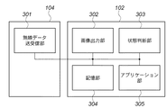
図2は、第1の実施形態におけるデジタルスチルカメラの構成の一例を示す図である。図2において、無線データ送受信部201は、近接無線転送技術を用いて無線でデータを送受信する。撮像部202は、CCDによって光学的に撮像した被写体の映像を電気信号に変換して出力する。状態判断部203は、プログラムに従って処理を行うCPUと周辺回路(タイマ)とを含み、デジタルスチルカメラ(以下、カメラと称す)101の状態を判断する。尚、この状態判断部203における判断の詳細については更に後述する。
FIG. 2 is a diagram illustrating an example of the configuration of the digital still camera according to the first embodiment. In FIG. 2, a wireless data transmission /
表示部204は、カメラ101への設定や撮像した画像などの表示を行うユーザインタフェースとして機能する。記憶部205は、撮像部202で撮像された映像を画像データファイルとして記憶する。アプリケーション部206は、カメラ101を画像供給装置として機能させるアプリケーションソフトウェアを含み、無線データ送受信部201と協働して画像データファイルをプロジェクタ102へ供給する。操作部207は、ユーザがカメラを操作するための各種ボタンを有する。
The
図3は、第1の実施形態におけるプロジェクタ及び無線ポートの構成の一例を示す図である。図3において、無線ポート104の無線データ送受信部301は、カメラ101の無線データ送受信部201と同様に、無線でデータを送受信する。画像出力部302は、無線データ送受信部301にて受信された画像データファイルをスクリーン103へ投影する。
FIG. 3 is a diagram illustrating an example of the configuration of the projector and the wireless port according to the first embodiment. In FIG. 3, the wireless data transmission /
状態判断部303は、プログラムに従って処理を行うCPUと周辺回路(タイマ)とを含み、近接無線転送技術によりカメラ101との接続状態を判断する。記憶部304は、画像データファイルを記憶する。アプリケーション部305は、アプリケーションソフトウェアを含み、無線データ送受信部201を介して受信された画像データファイルの保管処理や投影処理を行う。
The
以上の構成において、カメラ101の記憶部205に記憶されている複数の画像データファイルをプロジェクタ102へ転送する動作を説明する。
An operation of transferring a plurality of image data files stored in the
図4は、第1の実施形態における上位接続シーケンスを示す図である。また、図5は、第1の実施形態における上位切断シーケンスを示す図である。更に、図6は、第1の実施形態におけるメインシーケンスを示す図である。図4〜図6において、DSC-Appはカメラ101のアプリケーション部206、DSC-Networkはカメラ101の無線データ送受信部201である。そして、PJ-Networkは無線ポート104の無線データ送受信部301、PJ-Appはプロジェクタ102のアプリケーション部305である。
FIG. 4 is a diagram showing an upper connection sequence in the first embodiment. FIG. 5 is a diagram showing an upper disconnection sequence in the first embodiment. Furthermore, FIG. 6 is a diagram showing a main sequence in the first embodiment. 4 to 6, DSC-App is the
ここで、ユーザがカメラ101の表示部204に表示された画像をプロジェクタ102へ投影する場合、以下の操作が行われる。
Here, when the user projects an image displayed on the
まず、カメラ101を無線ポート104の一定距離内に近づける(401)。すると、近接無線転送機能によってカメラ101とプロジェクタ102が接続状態となる(402)。各装置の内部では、接続状態になったことをアプリケーション部206、305にそれぞれ通知する(403、404)。通知を受信したアプリケーション部206、305は、上位接続を行い(405)、画像転送状態へ遷移する。
First, the
次に、プロジェクタ102のアプリケーション部305が画像転送状態へ遷移すると、カメラ101に対して、予めカメラ101で選択されている画像データファイル群の転送を要求する(406〜408)。ここで、画像データファイル群はプロジェクタ102で選択する構成や全画像データファイルの転送を要求する構成も可能である。
Next, when the
画像データファイル群の転送要求を受信したカメラ101は、記憶部205に記憶した順のまま該当ファイルの転送を行う(409〜411)。そして、プロジェクタ102のアプリケーション部305が転送された画像データファイル群を記憶部304に格納する(412)。
Upon receiving the transfer request for the image data file group, the
尚、ここで、カメラ101のアプリケーション部206が画像転送状態へ遷移した後、プロジェクタ102側からの要求が無くても画像データファイル群の転送を開始する構成にしても良い。
Here, after the
カメラ101のアプリケーション部206は画像データファイル群の転送を完了すると、表示部204に表示している画像データファイルの名前をプロジェクタ102に送信する(413〜415)。これにより、プロジェクタ102のアプリケーション部305は、記憶部304に記憶した画像データファイルの中から、受信したファイル名で検索を行い、合致した画像データファイルを画像出力部302からスクリーン103へ投影する(416)。
When the transfer of the image data file group is completed, the
次に、スクリーン103へ投影している画像を、プロジェクタ102の記憶部304に記憶した順で、次の画像に変更する際のユーザ操作を説明する。ここでは、カメラ101を無線ポート104から遠ざけて無線による接続を切断した後に、一定時間内に、カメラ101を無線ポート104に近づけて接続状態とする操作を説明する。
Next, a user operation when changing the image projected on the
まず、無線ポート104に近づけてあったカメラ101を遠ざけ、カメラ101と無線ポート104と一定距離以上離す(501)。すると、近接無線転送機能によりカメラ101とプロジェクタ102が切断状態となる(502)。各装置の内部では、切断状態になったことをアプリケーション部206、305にそれぞれ通知する(503、504)。通知を受信したアプリケーション部206、305は、上位切断タイマを起動する。プロジェクタ102は投影を中止する。尚、タイマ値は予め装置が持っている構成でも、ユーザによって設定できる構成でも良い。
First, the
その後、上位切断タイマがタイムアウトすると(505、506)、上位切断を行い(507)、この画像転送状態を終了する。そして、アプリケーション部206、305は、画像転送状態時の設定をリセットする(508、509)。特に、プロジェクタ102の記憶部304に転送された画像データファイル群を消去する構成にすると良い。
Thereafter, when the upper disconnection timer times out (505, 506), upper disconnection is performed (507), and this image transfer state is terminated. Then, the
一方、ユーザが上位切断タイマのタイムアウト前に、カメラ101を無線ポート104に近づけると(605)、再度カメラ101とプロジェクタ102は接続状態となる(606)。そして、接続状態になったことをアプリケーション部206、305にそれぞれ通知する(607、608)。アプリケーション部206、305は、それぞれの装置で上位切断タイマが起動されていれば、上位切断タイマを停止する。
On the other hand, if the user brings the
また、通知を受けたプロジェクタ102のアプリケーション部305は、記憶部304に存在する次画像データファイルを画像出力部302からスクリーン103へ投影する(609)。ここで、次の画像データファイルの投影を開始したプロジェクタ102は、現在投影している画像データファイルのファイル名をカメラ101に送信するよう構成しても良い(610〜612)。その場合、投影した画像データファイルと同じ画像がカメラ101の表示部204で表示される(613)。尚、切断状態の時には画像の投影を継続する構成にしても良い。このように、カメラ101と無線ポート104とを近づけたり、遠ざけたりすることにより、投影画像を次々と切り替えることができる。
Upon receiving the notification, the
次に、スクリーン103へ投影している画像を、プロジェクタ102の記憶部304に記憶した順で、前の画像に変更する際のユーザ操作を説明する。つまり、ユーザがカメラ101の記憶部205に記憶されている前の画像をプロジェクタ102へ投影したい場合の操作である。
Next, a user operation when changing the image projected on the
まず、無線ポート104に近づけてあったカメラ101を遠ざける(614)。すると、近接無線転送機能によりカメラ101とプロジェクタ102が切断状態となる(615)。各装置の内部では、切断状態になったことをアプリケーション部206、305にそれぞれ通知する(616、617)。通知を受信したアプリケーション部206、305は、上位切断タイマを起動し、プロジェクタ102では投影を中止する。
First, the
ここで、ユーザが上位切断タイマのタイムアウト前に、カメラ101の操作部207の所定ボタンを押下しながら近づけると(618)、再度カメラ101とプロジェクタ102は接続状態となる(619)。尚、ボタンの押下は、カメラ101からプロジェクタ102へ通知されるものとする。そして、カメラ101のボタンが押下された状態で接続状態になったことをアプリケーション部206、305にそれぞれ通知する(620、621)。アプリケーション部206、305は、それぞれの装置で上位切断タイマを停止する。
Here, if the user approaches while pressing down a predetermined button of the
通知を受けたプロジェクタ102のアプリケーション部305は、状態判断部303の判断結果から、カメラ101のボタンが押下されたことを検知する(622)。そして、プロジェクタ102のアプリケーション部305は、記憶部304に記憶されている前画像データファイルを画像出力部302からスクリーン103へ投影する(623)。
The
尚、前画像データファイルの投影を開始したプロジェクタ102は、現在投影している画像データファイル名をカメラ101に送信する構成にしても良い(624〜626)。その場合、投影した画像データファイルと同じ画像がカメラ101の表示部204で表示される(627)。このように、一度、カメラ101と無線ポート104とを一度切断し、カメラ101のボタンを押下してカメラ101と無線ポート104とを再度近づければ、投影画像を前の画像に戻すことができる。従って、カメラ101と無線ポート104とを近づけたり、遠ざけたりする際に、カメラ101のボタンを押下するか、押下しないかによって、投影画像を進めたり、戻したりすることができる。
The
また、切断状態の時に、プロジェクタ102では画像の撮影を中止しているが、投影を継続する構成にしても良い。
Further, in the disconnected state, the
更に、近接無線転送技術を例に挙げて説明したが、Bluetooth(登録商標)やNFCなどの無線技術の接続/切断を使用することも可能である。 Furthermore, although the proximity wireless transfer technology has been described as an example, connection / disconnection of a wireless technology such as Bluetooth (registered trademark) or NFC can also be used.
また、カメラ101のボタンを押下しながら切断処理を行う場合を説明したが、裏返して近づける、又は加速度をつけて近づけるなど、状態が変わったことがセンサなどで認識できるならば、代替可能である。
In addition, the case where the cutting process is performed while pressing the button of the
第1の実施形態によれば、カメラとプロジェクタとの無線による接続の状態に応じて、プロジェクタが出力する画像データを異なる画像データに変更することが可能となる。 According to the first embodiment, the image data output from the projector can be changed to different image data in accordance with the wireless connection state between the camera and the projector.
[第2の実施形態]
次に、図面を参照しながら本発明に係る第2の実施形態を詳細に説明する。第2の実施形態では、近接無線転送における電磁波(電界強度)を測定し、電界強度の値に応じて、画像出力装置が出力する画像データを変更する場合を説明する。
[Second Embodiment]
Next, a second embodiment according to the present invention will be described in detail with reference to the drawings. In the second embodiment, a case will be described in which electromagnetic waves (electric field strength) in proximity wireless transfer are measured and image data output from the image output device is changed according to the value of the electric field strength.
尚、第2の実施形態における無線画像出力システムの構成は、図1〜図3を用いて説明した第1の実施形態の構成と同じであり、その説明は省略する。 Note that the configuration of the wireless image output system in the second embodiment is the same as the configuration of the first embodiment described with reference to FIGS.
また、カメラ101の記憶部205に記憶された画像データファイル群をプロジェクタ102の記憶部304に転送し、スクリーン103へ投影する場合の操作も、第1の実施形態と同じであり、その説明も省略する。
The operation when transferring the image data file group stored in the
ここでは、カメラ101を無線ポート104に近づけてプロジェクタ102と接続しておくものとし、プロジェクタ102には、近いか遠いかの判断に用いる電界強度の閾値を予め設定しておくものとする。
Here, it is assumed that the
また、無線を受信した際の電界強度値の測定は、無線ポート104の無線データ送受信部301が行うものとする。尚、測定は公知の測定方法で良く、その説明は省略する。
In addition, it is assumed that the wireless data transmission /
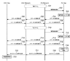
図7は、第2の実施形態におけるメインシーケンスを示す図である。ここで、ユーザがカメラ101の記憶部205に格納されている次画像をプロジェクタ102で投影したい場合は、以下のような操作を行う。
FIG. 7 is a diagram showing a main sequence in the second embodiment. Here, when the user wants to project the next image stored in the
無線ポート104に近づけてあったカメラ101を切断した程度の距離に遠ざける(701)。すると、無線ポート104が電界強度値をプロジェクタ102のアプリケーション部305に通知し、アプリケーション部305が電界強度値を受信する(702)。尚、通知のタイミングは、一定間隔や状態に変化があった場合、随時などが可能である。
The
そして、プロジェクタ102の状態判断部303が、予め設定されている閾値と、通知された電界強度値とを比較する。ここで電界強度値が閾値よりも低かった場合(703)、画像出力システムのステータスを変更する。具体的には、プロジェクタ102のアプリケーション部305から無線ポート104の無線データ送受信部301へステータス変更(弱)メッセージを送信する(704)。このメッセージは、近接無線転送機能により、カメラ101の無線データ送受信部201を経由して(705)、カメラ101のアプリケーション部206へ送信される(706)。
Then,
一方、ステータス変更(弱)メッセージを受信したカメラ101のアプリケーション部206は、その応答メッセージをプロジェクタ102のアプリケーション部305に送信する(707〜709)。アプリケーション部206、305は、それぞれステータスを変更し、上位切断タイマを起動する。プロジェクタ102は投影を中止する。尚、タイマ値は、予め装置が持っている構成でも、ユーザによって設定できる構成でも良い。
On the other hand, the
また、ユーザが上位切断タイマのタイムアウト前に、カメラ101を無線ポート104に近づけると(710)、電界強度値をプロジェクタ102のアプリケーション部305に通知する(711)。これにより、再度プロジェクタ102の状態判断部303では、閾値との比較を行う。ここで、電界強度値が閾値よりも高かった場合は(712)、画像出力システムのステータスを変更する。つまり、プロジェクタ102のアプリケーション部305から無線ポート104の無線データ送受信部301へステータス変更(強)メッセージを送信する(713)。このメッセージは、近接無線転送機能により、カメラ101の無線データ送受信部201を経由して(714)、カメラ101のアプリケーション部206へ送信される(715)。
When the user brings the
一方、ステータス変更(強)メッセージを受信したカメラ101のアプリケーション部206は、その応答メッセージをプロジェクタ102のアプリケーション部305に送信する(716〜718)。アプリケーション部206、305は、それぞれステータスを変更し、上位切断タイマを停止する。
On the other hand, the
次に、ステータス変更(強)メッセージを受けたプロジェクタ102のアプリケーション部305は、記憶部304に記憶されている次画像データファイルを画像出力部302からスクリーン103へ投影する(719)。ここで次画像データファイルの投影を開始したプロジェクタ102は、現在投影している画像データファイル名をカメラ101に送信する構成にしても良い(720〜722)。その場合、投影した画像データファイルと同じ画像がカメラ101の表示部204で表示される(723)。
Next, the
尚、プロジェクタ102のステータスを(弱)状態に変更した時に、画像の投影を継続する構成にしても良い。
It should be noted that when the status of the
また、第2の実施形態における他の処理は、第1の実施形態と同様であり、その説明は省略する。つまり、操作部207のボタンを押下してカメラ101と無線ポート104とを近づけたり、遠ざけたりすれば、投影画像を前の画像に戻すこともできる。
In addition, other processes in the second embodiment are the same as those in the first embodiment, and a description thereof will be omitted. That is, the projected image can be returned to the previous image by pressing the button on the
第2の実施形態によれば、無線の電界強度の値に応じて、プロジェクタからスクリーンへ投影する画像を異なる画像に変更することが可能となる。 According to the second embodiment, the image projected from the projector onto the screen can be changed to a different image according to the value of the wireless electric field strength.
[第3の実施形態]
次に、図面を参照しながら本発明に係る第3の実施形態を詳細に説明する。第3の実施形態では、近接無線転送機能による無線接続方法に応じて、画像出力装置が出力する画像データファイルを変更する場合を説明する。
[Third Embodiment]
Next, a third embodiment according to the present invention will be described in detail with reference to the drawings. In the third embodiment, a case will be described in which the image data file output from the image output apparatus is changed according to the wireless connection method using the proximity wireless transfer function.
尚、第2の実施形態における無線画像出力システムの構成は、図1〜図3を用いて説明した第1の実施形態の構成と同じであり、その説明は省略する。 Note that the configuration of the wireless image output system in the second embodiment is the same as the configuration of the first embodiment described with reference to FIGS.
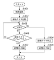
図8は、第3の実施形態における無線接続方法の判断処理を示すフローチャートである。尚、この判断処理は、カメラ101のアプリケーション部206とプロジェクタ102のアプリケーション部305とで行われる処理である。ここでは、無線接続方法として、接触処理Aと接触処理Bを例に挙げて説明する。
FIG. 8 is a flowchart illustrating the determination process of the wireless connection method according to the third embodiment. This determination processing is processing performed by the
まず、ステップS801で、カメラ101の無線データ送受信部201と無線ポート104の無線データ送受信部301が無線接続を行う。そして、接続が完了するとステップS802で、カメラ101のアプリケーション部206とプロジェクタ102のアプリケーション部305が接続の維持時間を監視する接続タイマを起動する。タイムアウト値はカメラ101とプロジェクタ102がそれぞれ持っているものとする。
First, in step S801, the wireless data transmission /
次に、アプリケーション部206、305が、それぞれ接続タイマがタイムアウトする前に切断されたか否かを判定する。ここで、接続タイマがタイムアウトする前に切断されたと判定した場合は、ステップS804へ処理を進め、接続タイマを停止する。そして、ステップS805で、接触処理Bと判断する。つまり、この接触処理Bは、無線接続した後に、すぐに接続を切断するものである。
Next, the
一方、ステップS803で接続を維持し続け、ステップS806で接続タイマがタイムアウトした場合はステップS807へ処理を進める。このステップS807では、アプリケーション部206、305は接触処理Aと判断する。尚、予めタイムアウト値をユーザが設定できるような構成も可能である。
On the other hand, if the connection continues in step S803 and the connection timer times out in step S806, the process proceeds to step S807. In step S807, the
ここで、上述した接触処理を用いて画像出力システムで投影する画像を変更する処理を説明する。カメラ101の記憶部205の画像データファイル群をプロジェクタ102の記憶部304に転送し、カメラ101の表示部204の画像データをプロジェクタ102へ投影する場合の操作は、第1の実施形態と同様である。以下、ユーザがカメラ101の記憶部205に格納されている次の画像をプロジェクタ102へ投影する場合を、図9を用いて説明する。
Here, a process of changing an image projected by the image output system using the contact process described above will be described. The operations for transferring the image data file group in the
図9は、第3の実施形態におけるメインシーケンスを示す図である。まず、無線ポート104に近づけてあったカメラ101を遠ざける(901)。すると、近接無線転送機能により、カメラ101とプロジェクタ102は切断状態となる(902)。各装置の内部では、切断状態になったことをアプリケーション部206、305にそれぞれ通知する(903、904)。通知を受信したアプリケーション部206、305は、上位切断タイマを起動する。プロジェクタ102は投影を中止する。尚、タイマ値は予め装置が持っている構成でも、ユーザによって設定できる構成でも良い。
FIG. 9 is a diagram showing a main sequence in the third embodiment. First, the
一方、ユーザが上位切断タイマのタイムアウト前に、接触処理Aを用いてカメラ101を無線ポート104に近づけた場合(905)、再度カメラ101とプロジェクタ102は接続状態となる(906)。ここで、アプリケーション部206、305が、接触処理の判断を行い(907、908)、それぞれ上位切断タイマを停止する。
On the other hand, when the user brings the
ここで接触処理Aと判断すると、プロジェクタ102のアプリケーション部305は、記憶部304に記憶されている次画像データファイルを画像出力部302からスクリーン103へ投影する(909)。ここで、次画像データファイルの投影を開始したプロジェクタ102は、現在投影している画像データファイルのファイル名をカメラ101に送信する構成にしても良い(910〜912)。その場合、投影した画像データファイルと同じ画像がカメラ101の表示部204で表示される(913)。尚、切断状態の時には画像の投影を継続する構成にしても良い。
If the contact process A is determined here, the
次に、ユーザがカメラ101の記憶部205に格納されている前の画像をプロジェクタ102がスクリーン103へ投影する場合の処理を説明する。
Next, a process when the
まず、無線ポート104に近づけてあったカメラ101を遠ざける(914)。すると、近接無線転送機能によりカメラ101とプロジェクタ102は切断状態となる(915)。各装置の内部では、切断状態になったことをアプリケーション部206、305にそれぞれ通知する(916、917)。通知を受信したアプリケーション部206、305は、上位切断タイマを起動し、プロジェクタ102では投影を中止する。
First, the
ここで、ユーザが上位切断タイマのタイムアウト前に、接触処理Bを用いてカメラ101を無線ポート104に近づけると(918)、再度カメラ101とプロジェクタ102は接続状態となるが(919)、すぐに切断状態となる(920)。アプリケーション部206、305は、接触処理の判断を行い(921、922)、それぞれ上位切断タイマを停止する。尚、図9には、無線接続通知と無線切断通知を図示していないが、通知するような構成も可能である。
Here, if the user brings the
接触処理Bと判断したプロジェクタ102のアプリケーション部305は、前画像データファイルを記憶部205より読み込み、画像出力部302からスクリーン103へ投影する(923)。
The
尚、第3の実施形態における他の処理は、第1及び第2の実施形態と同様であり、その説明は省略する。 Note that other processes in the third embodiment are the same as those in the first and second embodiments, and a description thereof will be omitted.
第3の実施形態によれば、カメラ101とプロジェクタ102とで、無線による接続が切断されるまでの維持時間に応じて、投影する画像を異なる画像に変更することが可能となる。
According to the third embodiment, the projected image can be changed to a different image between the
尚、本発明は複数の機器(例えば、ホストコンピュータ、インターフェース機器、リーダ、プリンタなど)から構成されるシステムに適用しても、1つの機器からなる装置(例えば、複写機、ファクシミリ装置など)に適用しても良い。 Even if the present invention is applied to a system constituted by a plurality of devices (for example, a host computer, an interface device, a reader, a printer, etc.), it is applied to an apparatus (for example, a copying machine, a facsimile machine, etc.) comprising a single device. It may be applied.
また、前述した実施形態の機能を実現するソフトウェアのプログラムコードを記録した記録媒体を、システム或いは装置に供給し、そのシステム或いは装置のコンピュータ(CPU若しくはMPU)が記録媒体に格納されたプログラムコードを読出し実行する。これによっても、本発明の目的が達成されることは言うまでもない。 In addition, a recording medium in which a program code of software for realizing the functions of the above-described embodiments is recorded is supplied to the system or apparatus, and the computer (CPU or MPU) of the system or apparatus stores the program code stored in the recording medium. Read and execute. It goes without saying that the object of the present invention can also be achieved by this.
この場合、コンピュータ読み取り可能な記録媒体から読出されたプログラムコード自体が前述した実施形態の機能を実現することになり、そのプログラムコードを記憶した記録媒体は本発明を構成することになる。 In this case, the program code itself read from the computer-readable recording medium realizes the functions of the above-described embodiments, and the recording medium storing the program code constitutes the present invention.
このプログラムコードを供給するための記録媒体として、例えばフレキシブルディスク、ハードディスク、光ディスク、光磁気ディスク、CD−ROM、CD−R、磁気テープ、不揮発性のメモリカード、ROMなどを用いることができる。 As a recording medium for supplying the program code, for example, a flexible disk, a hard disk, an optical disk, a magneto-optical disk, a CD-ROM, a CD-R, a magnetic tape, a nonvolatile memory card, a ROM, or the like can be used.
また、コンピュータが読出したプログラムコードを実行することにより、前述した実施形態の機能が実現されるだけでなく、次の場合も含まれることは言うまでもない。即ち、プログラムコードの指示に基づき、コンピュータ上で稼働しているOS(オペレーティングシステム)などが実際の処理の一部又は全部を行い、その処理により前述した実施形態の機能が実現される場合である。 In addition, by executing the program code read by the computer, not only the functions of the above-described embodiments are realized, but also the following cases are included. That is, based on the instruction of the program code, an OS (operating system) running on the computer performs part or all of the actual processing, and the functions of the above-described embodiments are realized by the processing. .
更に、記録媒体から読出されたプログラムコードがコンピュータに挿入された機能拡張ボードやコンピュータに接続された機能拡張ユニットに備わるメモリに書込む。その後、そのプログラムコードの指示に基づき、その機能拡張ボードや機能拡張ユニットに備わるCPUなどが実際の処理の一部又は全部を行い、その処理により前述した実施形態の機能が実現される場合も含まれることは言うまでもない。 Further, the program code read from the recording medium is written in a memory provided in a function expansion board inserted into the computer or a function expansion unit connected to the computer. After that, based on the instruction of the program code, the CPU of the function expansion board or function expansion unit performs part or all of the actual processing, and the processing of the above-described embodiment is realized by the processing. Needless to say.
101 デジタルスチルカメラ
102 プロジェクタ
103 スクリーン
104 無線ポート
201 無線データ送受信部
202 撮像部
203 状態判断部
204 表示部
205 記憶部
206 アプリケーション部
301 無線データ送受信部
302 画像出力部
303 状態判断部
304 記憶部
305 アプリケーション部
DESCRIPTION OF
Claims (9)
画像供給装置と前記画像出力装置との間を無線により接続し、データ送受信を行う送受信手段と、
前記無線による接続の状態を判断する判断手段と、
前記判断手段で判断された接続の状態に応じて、出力する画像を変更する変更手段と、
を有することを特徴とする画像出力装置。 An image output device,
A transmission / reception means for wirelessly connecting between the image supply device and the image output device, and transmitting and receiving data;
Determining means for determining a wireless connection state;
Changing means for changing an image to be output according to the connection state determined by the determining means;
An image output apparatus comprising:
前記変更手段は、前記無線による接続が切断された後に、再度、接続されたと判断された場合、前記記憶手段に記憶されている次の画像を出力することを特徴とする請求項1に記載の画像出力装置。 Storage means for storing the image supplied from the image supply device;
The said change means outputs the next image memorize | stored in the said memory | storage means, when it is judged that it was connected again after the said wireless connection was cut | disconnected. Image output device.
前記変更手段は、前記無線による接続が切断された後、所定の操作が行われた状態の画像供給装置が再度、接続されたと判断された場合、前記記憶手段から前に出力した画像を出力することを特徴とする請求項1に記載の画像出力装置。 Storage means for storing image data supplied from the image supply device;
The change unit outputs the image output previously from the storage unit when it is determined that the image supply device in a state where a predetermined operation has been performed is connected again after the wireless connection is disconnected. The image output apparatus according to claim 1.
前記変更手段は、前記測定された電界強度の値に応じて、出力する画像を変更することを特徴とする請求項1に記載の画像出力装置。 The determination means includes means for measuring electric field strength when receiving the radio,
The image output apparatus according to claim 1, wherein the changing unit changes an image to be output according to the value of the measured electric field strength.
画像供給装置と前記画像出力装置との間を無線により接続し、データ送受信を行う送受信工程と、
前記無線による接続の状態を判断する判断工程と、
前記判断工程において判断した接続の状態に応じて、出力する画像を変更する変更工程と、
を有することを特徴とする画像出力方法。 An image output method executed by an image output device,
A transmission / reception step of wirelessly connecting between the image supply device and the image output device to perform data transmission / reception,
A determination step of determining a wireless connection state;
According to the connection state determined in the determination step, a change step for changing the image to be output;
An image output method comprising:
前記画像供給装置と前記画像出力装置との間を無線により接続し、データ送受信を行う送受信手段と、
前記無線による接続の状態を判断する判断手段と、
前記判断手段で判断された接続の状態に応じて、前記画像出力装置が出力する画像を変更する変更手段と、
を有することを特徴とする画像出力システム。 An image output system having an image supply device and an image output device,
A transmission / reception unit that wirelessly connects the image supply device and the image output device, and transmits and receives data;
Determining means for determining a wireless connection state;
Changing means for changing an image output by the image output device in accordance with the state of connection determined by the determining means;
An image output system comprising:
Priority Applications (9)
| Application Number | Priority Date | Filing Date | Title |
|---|---|---|---|
| JP2008171245A JP5075032B2 (en) | 2008-06-30 | 2008-06-30 | Communication apparatus and communication method |
| CN201310455342.8A CN103533207B (en) | 2008-06-30 | 2009-06-09 | Communications apparatus and control method |
| EP09773298.6A EP2308223B1 (en) | 2008-06-30 | 2009-06-09 | Data output apparatus, method of controlling same and output system |
| EP16195813.7A EP3151530A1 (en) | 2008-06-30 | 2009-06-09 | Data output apparatus, method of controlling same and output system |
| CN2009801253245A CN102077566B (en) | 2008-06-30 | 2009-06-09 | Data output apparatus, method of controlling same and output system |
| CN201310456212.6A CN103546202B (en) | 2008-06-30 | 2009-06-09 | Communication equipment and communication means thereof |
| PCT/JP2009/060967 WO2010001720A1 (en) | 2008-06-30 | 2009-06-09 | Data output apparatus, method of controlling same and output system |
| US12/988,628 US8818281B2 (en) | 2008-06-30 | 2009-06-09 | Data output apparatus, method of controlling same and output system |
| US14/444,871 US9614986B2 (en) | 2008-06-30 | 2014-07-28 | Data output apparatus, method of controlling same and output system |
Applications Claiming Priority (1)
| Application Number | Priority Date | Filing Date | Title |
|---|---|---|---|
| JP2008171245A JP5075032B2 (en) | 2008-06-30 | 2008-06-30 | Communication apparatus and communication method |
Publications (3)
| Publication Number | Publication Date |
|---|---|
| JP2010011367A true JP2010011367A (en) | 2010-01-14 |
| JP2010011367A5 JP2010011367A5 (en) | 2011-08-04 |
| JP5075032B2 JP5075032B2 (en) | 2012-11-14 |
Family
ID=41465823
Family Applications (1)
| Application Number | Title | Priority Date | Filing Date |
|---|---|---|---|
| JP2008171245A Active JP5075032B2 (en) | 2008-06-30 | 2008-06-30 | Communication apparatus and communication method |
Country Status (5)
| Country | Link |
|---|---|
| US (2) | US8818281B2 (en) |
| EP (2) | EP3151530A1 (en) |
| JP (1) | JP5075032B2 (en) |
| CN (3) | CN103546202B (en) |
| WO (1) | WO2010001720A1 (en) |
Cited By (2)
| Publication number | Priority date | Publication date | Assignee | Title |
|---|---|---|---|---|
| JP2012085269A (en) * | 2010-09-16 | 2012-04-26 | Ricoh Co Ltd | Transmission terminal, display data transmission method, program, information provision device and transmission system |
| JP2020022070A (en) * | 2018-07-31 | 2020-02-06 | 株式会社リコー | Communication system, mobile terminal, communication method, and program |
Families Citing this family (9)
| Publication number | Priority date | Publication date | Assignee | Title |
|---|---|---|---|---|
| WO2006033439A1 (en) | 2004-09-21 | 2006-03-30 | Showa Denko K.K. | Heat-curable urethane resin composition |
| JP5171436B2 (en) | 2008-06-30 | 2013-03-27 | キヤノン株式会社 | COMMUNICATION DEVICE, DATA COMMUNICATION SYSTEM, COMMUNICATION DEVICE CONTROL METHOD, AND PROGRAM |
| JP5075032B2 (en) | 2008-06-30 | 2012-11-14 | キヤノン株式会社 | Communication apparatus and communication method |
| EP2742770A4 (en) * | 2011-08-08 | 2015-03-18 | Blackberry Ltd | Methods and apparatus to obtain and present information |
| CN102866567B (en) * | 2012-09-13 | 2014-11-05 | 深圳雅图数字视频技术有限公司 | Intelligent NFC projector and control method thereof |
| CN103412458A (en) * | 2013-08-30 | 2013-11-27 | 苏州跨界软件科技有限公司 | System and method for projection based on NFC |
| CN103747242B (en) * | 2013-12-23 | 2016-05-11 | 乐视致新电子科技(天津)有限公司 | A kind of method of automatic detection picture pick-up device and checkout equipment |
| JP5980258B2 (en) * | 2014-03-11 | 2016-08-31 | キヤノン株式会社 | Information processing apparatus, information processing apparatus control method, and program |
| CN105158793A (en) * | 2015-07-15 | 2015-12-16 | 安徽吉思勘仪器科技有限公司 | Cable-free seismic data acquisition system based on high-speed field data collection |
Citations (3)
| Publication number | Priority date | Publication date | Assignee | Title |
|---|---|---|---|---|
| JPH08195871A (en) * | 1995-01-19 | 1996-07-30 | Sanyo Electric Co Ltd | Picture communication equipment |
| JP2000209653A (en) * | 1999-01-18 | 2000-07-28 | Kobe Steel Ltd | Radiotelephony system |
| JP2008041225A (en) * | 2006-08-10 | 2008-02-21 | Alpine Electronics Inc | Audio/video reproducing system, audio/video system, and updated information notifying method |
Family Cites Families (20)
| Publication number | Priority date | Publication date | Assignee | Title |
|---|---|---|---|---|
| JP3562178B2 (en) | 1996-10-23 | 2004-09-08 | オムロン株式会社 | Non-contact medium processing device and entry / exit management device, and non-contact medium processing method and entry / exit management method |
| JP4186465B2 (en) * | 2000-05-31 | 2008-11-26 | セイコーエプソン株式会社 | projector |
| US7433546B2 (en) | 2004-10-25 | 2008-10-07 | Apple Inc. | Image scaling arrangement |
| JP3870882B2 (en) | 2002-09-12 | 2007-01-24 | ソニー株式会社 | Information communication system, information communication apparatus, information communication method, and computer program |
| JP4343524B2 (en) * | 2002-12-13 | 2009-10-14 | キヤノン株式会社 | Control device and digital video device |
| JP2004240825A (en) * | 2003-02-07 | 2004-08-26 | Toshiba Corp | Information processor and method for controlling transmission of picture data |
| JP2004312081A (en) * | 2003-04-02 | 2004-11-04 | Matsushita Electric Ind Co Ltd | Broadcast wave receiver |
| JP2004328275A (en) * | 2003-04-23 | 2004-11-18 | Canon Inc | Image pickup device, printing system including the same and printing control method therefor |
| KR100524588B1 (en) * | 2003-06-19 | 2005-10-31 | 에스케이 텔레콤주식회사 | succeeding method of data in mobile |
| JP2005177763A (en) * | 2003-12-16 | 2005-07-07 | Disco Abrasive Syst Ltd | Verifying apparatus for affected layer machined by laser beam |
| JP2005210304A (en) * | 2004-01-21 | 2005-08-04 | Matsushita Electric Ind Co Ltd | Wireless communication system |
| JP2005223518A (en) * | 2004-02-04 | 2005-08-18 | Seiko Epson Corp | Image supplying apparatus, image storing apparatus, automatic storing system and image storing method |
| US20050215283A1 (en) * | 2004-03-25 | 2005-09-29 | Camp William O Jr | Hand-held electronic devices configured to provide image data in an internet protocol format and related display devices and mehods |
| TWI289389B (en) * | 2004-12-15 | 2007-11-01 | Univ Tsinghua | Roaming system and method for heterogeneous wireless network environment |
| JP4746315B2 (en) * | 2004-12-27 | 2011-08-10 | 株式会社東芝 | Electronics |
| JP4366339B2 (en) * | 2005-06-09 | 2009-11-18 | 株式会社リコー | Image processing apparatus, program, and recording medium |
| JP4634878B2 (en) | 2005-07-07 | 2011-02-16 | 株式会社東芝 | Wireless communication device |
| KR100726128B1 (en) * | 2005-07-22 | 2007-06-12 | 정 현 이 | Mobile terminal which enables image projection |
| KR100677623B1 (en) | 2005-12-13 | 2007-02-02 | 삼성전자주식회사 | Method and apparatus for remote controlling image forming apparatus using wireless data communication |
| JP5075032B2 (en) | 2008-06-30 | 2012-11-14 | キヤノン株式会社 | Communication apparatus and communication method |
-
2008
- 2008-06-30 JP JP2008171245A patent/JP5075032B2/en active Active
-
2009
- 2009-06-09 CN CN201310456212.6A patent/CN103546202B/en active Active
- 2009-06-09 CN CN201310455342.8A patent/CN103533207B/en active Active
- 2009-06-09 EP EP16195813.7A patent/EP3151530A1/en not_active Withdrawn
- 2009-06-09 EP EP09773298.6A patent/EP2308223B1/en active Active
- 2009-06-09 US US12/988,628 patent/US8818281B2/en active Active
- 2009-06-09 CN CN2009801253245A patent/CN102077566B/en active Active
- 2009-06-09 WO PCT/JP2009/060967 patent/WO2010001720A1/en active Application Filing
-
2014
- 2014-07-28 US US14/444,871 patent/US9614986B2/en active Active
Patent Citations (3)
| Publication number | Priority date | Publication date | Assignee | Title |
|---|---|---|---|---|
| JPH08195871A (en) * | 1995-01-19 | 1996-07-30 | Sanyo Electric Co Ltd | Picture communication equipment |
| JP2000209653A (en) * | 1999-01-18 | 2000-07-28 | Kobe Steel Ltd | Radiotelephony system |
| JP2008041225A (en) * | 2006-08-10 | 2008-02-21 | Alpine Electronics Inc | Audio/video reproducing system, audio/video system, and updated information notifying method |
Cited By (2)
| Publication number | Priority date | Publication date | Assignee | Title |
|---|---|---|---|---|
| JP2012085269A (en) * | 2010-09-16 | 2012-04-26 | Ricoh Co Ltd | Transmission terminal, display data transmission method, program, information provision device and transmission system |
| JP2020022070A (en) * | 2018-07-31 | 2020-02-06 | 株式会社リコー | Communication system, mobile terminal, communication method, and program |
Also Published As
| Publication number | Publication date |
|---|---|
| JP5075032B2 (en) | 2012-11-14 |
| CN103533207B (en) | 2017-04-12 |
| CN103546202B (en) | 2016-03-30 |
| CN102077566A (en) | 2011-05-25 |
| WO2010001720A1 (en) | 2010-01-07 |
| CN103533207A (en) | 2014-01-22 |
| CN102077566B (en) | 2013-10-30 |
| EP2308223A4 (en) | 2012-01-25 |
| US20140333781A1 (en) | 2014-11-13 |
| EP3151530A1 (en) | 2017-04-05 |
| US9614986B2 (en) | 2017-04-04 |
| CN103546202A (en) | 2014-01-29 |
| EP2308223B1 (en) | 2016-12-14 |
| US20110045774A1 (en) | 2011-02-24 |
| US8818281B2 (en) | 2014-08-26 |
| EP2308223A1 (en) | 2011-04-13 |
Similar Documents
| Publication | Publication Date | Title |
|---|---|---|
| JP5075032B2 (en) | Communication apparatus and communication method | |
| JP4006452B2 (en) | COMMUNICATION DEVICE, COMMUNICATION METHOD, AND COMPUTER PROGRAM FOR CAUSING COMPUTER TO EXECUTE THE COMMUNICATION METHOD | |
| US7760232B2 (en) | Slave device and communication setting method | |
| US9237413B2 (en) | Data supplying apparatus, data processing apparatus and data communication system | |
| US9794480B2 (en) | Communication apparatus, control method of communication apparatus and program that controls power source of a different communication apparatus | |
| JP5149715B2 (en) | COMMUNICATION SYSTEM, COMMUNICATION DEVICE, ITS CONTROL METHOD, PROGRAM | |
| JP2005078304A (en) | Usb function device | |
| US20100159831A1 (en) | Communication apparatus and method for controlling the communication apparatus | |
| JP2006261852A (en) | Radio communications equipment and communication method thereof | |
| US9485431B2 (en) | Image capturing apparatus and method for controlling the same | |
| RU2635282C2 (en) | Connection device and method for controlling communication device | |
| JP2004284318A (en) | Printing system, printer, and printer control device | |
| JP4514604B2 (en) | USB device system, digital printer and digital camera | |
| US10142497B2 (en) | Image printing system, method in image processing apparatus, and storage medium | |
| JP6632328B2 (en) | Control device, power transmission device, control method, and program | |
| EP3506620B1 (en) | Communication apparatus, method for controlling the communication apparatus and computer program | |
| JP2011097180A (en) | Camera, and information processing system | |
| US20190281615A1 (en) | Communication control apparatus and communication control method | |
| JP2007129771A (en) | Image processor, its control method, and program | |
| JP2004229328A (en) | Electronic imaging apparatus | |
| JP2010004394A (en) | Communication apparatus, control method thereof, and program | |
| JP2010004477A (en) | Communication apparatus, control method thereof, and program |
Legal Events
| Date | Code | Title | Description |
|---|---|---|---|
| A521 | Request for written amendment filed |
Free format text: JAPANESE INTERMEDIATE CODE: A523 Effective date: 20110622 |
|
| A621 | Written request for application examination |
Free format text: JAPANESE INTERMEDIATE CODE: A621 Effective date: 20110622 |
|
| A131 | Notification of reasons for refusal |
Free format text: JAPANESE INTERMEDIATE CODE: A131 Effective date: 20120514 |
|
| A521 | Request for written amendment filed |
Free format text: JAPANESE INTERMEDIATE CODE: A523 Effective date: 20120620 |
|
| TRDD | Decision of grant or rejection written | ||
| A01 | Written decision to grant a patent or to grant a registration (utility model) |
Free format text: JAPANESE INTERMEDIATE CODE: A01 Effective date: 20120727 |
|
| A01 | Written decision to grant a patent or to grant a registration (utility model) |
Free format text: JAPANESE INTERMEDIATE CODE: A01 |
|
| A61 | First payment of annual fees (during grant procedure) |
Free format text: JAPANESE INTERMEDIATE CODE: A61 Effective date: 20120824 |
|
| R151 | Written notification of patent or utility model registration |
Ref document number: 5075032 Country of ref document: JP Free format text: JAPANESE INTERMEDIATE CODE: R151 |
|
| FPAY | Renewal fee payment (event date is renewal date of database) |
Free format text: PAYMENT UNTIL: 20150831 Year of fee payment: 3 |