JP2010010871A - Wireless transmission device, and wireless communication system using it - Google Patents
Wireless transmission device, and wireless communication system using it Download PDFInfo
- Publication number
- JP2010010871A JP2010010871A JP2008165441A JP2008165441A JP2010010871A JP 2010010871 A JP2010010871 A JP 2010010871A JP 2008165441 A JP2008165441 A JP 2008165441A JP 2008165441 A JP2008165441 A JP 2008165441A JP 2010010871 A JP2010010871 A JP 2010010871A
- Authority
- JP
- Japan
- Prior art keywords
- frequency
- signal
- wireless
- transmission
- radio
- Prior art date
- Legal status (The legal status is an assumption and is not a legal conclusion. Google has not performed a legal analysis and makes no representation as to the accuracy of the status listed.)
- Granted
Links
Images


Landscapes
- Transmitters (AREA)
- Circuits Of Receivers In General (AREA)
- Superheterodyne Receivers (AREA)
Abstract
Description
本発明は、FSK(Frequency Shift Keying)、又はFM(Frequency Modulation)変調方式の無線送信装置、及びこれを用いた無線通信システムに関する。 The present invention relates to a radio transmission apparatus using FSK (Frequency Shift Keying) or FM (Frequency Modulation) modulation, and a radio communication system using the same.
高精細な画像や動画など大容量のデータを伝送する無線通信システムにおいて、高速な通信速度が要求されるのは言うまでもないが、機器の制御信号など比較的小容量のデータを伝送する無線通信システムにおいても高速な通信速度が要求される場合がある。その一例は、送信器が電池を電源として駆動している場合である。 In a wireless communication system that transmits a large amount of data such as high-definition images and moving images, it is needless to say that a high communication speed is required, but a wireless communication system that transmits a relatively small amount of data such as a control signal of a device. In some cases, a high communication speed may be required. One example is a case where the transmitter is driven by a battery as a power source.
電池駆動の送信器においては、その消費電力を低減することが特に強く求められる。消費電力を低減することにより、小型の電池が使用可能になり機器を小型化できる、電池交換や充電の必要がなくなる(または頻度を少なくすることができる)ためメンテナンス性が向上したり、電池交換や充電が可能な構造をとる必要がなくなり機器の小型化や低コスト化ができたりするなど、様々な利点を得ることができる。 In battery-powered transmitters, it is particularly strongly required to reduce power consumption. By reducing power consumption, small batteries can be used and the equipment can be miniaturized. There is no need for battery replacement or charging (or frequency can be reduced), so maintenance is improved and battery replacement is possible. In addition, it is not necessary to adopt a structure that can be charged and various advantages can be obtained, such as downsizing and cost reduction of the device.
送信器の消費電力を低減する方法の1つとして、通信時間を短縮することが挙げられる。ある容量のデータを送信する場合に、通信時間を短縮するほど送信器を駆動させる時間を短くすることができる。その結果、消費電力を低減できる。 One method for reducing the power consumption of the transmitter is to shorten the communication time. When transmitting a certain amount of data, the time for driving the transmitter can be shortened as the communication time is shortened. As a result, power consumption can be reduced.
図16は、背景技術に係る無線通信システムの構成を示すブロック図である。図16に示す無線通信システムは、無線送信装置100と、無線受信装置110とを備えている。無線送信装置100は、送信制御回路101、送信RF(Radio Frequency)回路102、パワーアンプ103、送信アンテナ104、及び基準発振器105から構成される。送信制御回路101は送信トリガを検出すると、送信データを送信RF回路102に送出する。
FIG. 16 is a block diagram illustrating a configuration of a wireless communication system according to the background art. The wireless communication system illustrated in FIG. 16 includes a
送信RF回路102は、基準発振器105で生成された基準発振周波数の発振信号を用いて、送信データに対して所定のFM変調動作を行い、その変調信号をパワーアンプ103に送出する。基準発振周波数は、例えば搬送波の周波数として用いられる。
The
パワーアンプ103は変調信号を増幅し、送信アンテナ104に伝達し、送信アンテナ104より空間に放射する。送信RF回路は、FM変調動作を行うにあたり、周波数偏移を可変な構成とし、周波数偏移は送信制御回路101より制御する。
The
無線受信装置110は、受信アンテナ111、ローノイズアンプ112、RFフィルタ113、ミキサ114、IF(Intermediate Frequency)フィルタ115、IFアンプ116、検波器117、べースバンド回路部118、自動周波数調整回路119、及び局部発振回路120から構成される。
The
受信アンテナ111で受信された高周波信号は、ローノイズアンプ112で増幅されRFフィルタ113で不要周波数成分を除去された後、ミキサ114によって局部発振回路120から出力される基準発振周波数(局部発振周波数)の出力信号とミキシングされ、IF信号に変換される。IF信号はIFフィルタ115にて不要周波数成分を除去された後IFアンプで増幅され、検波器117によって周波数−電圧変換された後べースバンド回路部118に伝達される。
The high frequency signal received by the
ここで、無線送信装置100の基準発振周波数と無線受信装置110の基準発振周波数とが、温度の影響を受けるなどして互いにずれている場合、IF信号のIF周波数が設計値から外れる。このとき、検波器117によって周波数−電圧変換された信号も、設計値から外れてしまい、受信感度が低下する。
Here, when the reference oscillation frequency of the
そこで、検波器117の出力信号が自動周波数調整回路119に入力されるようになっている。そして、自動周波数調整回路119によって、IF周波数が設計値に収束するように局部発振回路120の局部発振周波数が、無線送信装置100の基準発振周波数に合わせるように調節されて、受信感度の低下が抑制されるようになっている(例えば、特許文献1参照。)。
Therefore, the output signal of the
また、一般に、FSK変調方式やFM変調方式の無線通信システムにおいて、高速な通信速度と高い通信信頼性を両立させるためには周波数偏移(Frequency Deviation)を大きくする必要がある。周波数偏移を大きくすると、変調信号の周波数スペクトラムが広がるため、それに応じて無線受信装置110に設けられているIFフィルタ115の通過帯域幅を広く設計する必要がある。変調周波数をfMOD、周波数偏移をfDEVとすると、IFフィルタ115に要求される通過帯域幅BIF’は近似的に下記の式(2)で表される(カーソン則)。
In general, in a radio communication system using an FSK modulation scheme or an FM modulation scheme, it is necessary to increase the frequency deviation in order to achieve both high communication speed and high communication reliability. When the frequency deviation is increased, the frequency spectrum of the modulation signal is expanded, and accordingly, the pass band width of the
BIF’≧2×(fMOD+fDEV) ・・・(2)
さらに、無線通信システムの低コスト化を図るために、無線送信装置100側の基準発振器105や無線受信装置110の局部発振回路120に、温度補償機能をもたない低コストの発振器を使用する場合がある。このような場合、送受信器それぞれの基準発振周波数の温度変化をも考慮する必要があるため、IFフィルタ115に要求される通過帯域幅BIFは、下記の式(3)で示される。
B IF '≧ 2 × (f MOD + f DEV ) (2)
Further, in order to reduce the cost of the wireless communication system, a low-cost oscillator having no temperature compensation function is used for the
BIF≧2×(fMOD+fDEV+△fTX+△fRX) ・・・(3)
ここで、△fTXは送信装置側における基準発振周波数の最大の偏差(偏差の絶対値の最大値)、△fRXは受信装置側における基準発振周波数の最大の偏差(偏差の絶対値の最大値)である。
B IF ≧ 2 × (f MOD + f DEV + Δf TX + Δf RX ) (3)
Here, Δf TX is the maximum deviation of the reference oscillation frequency on the transmitter side (maximum value of deviation), and Δf RX is the maximum deviation of the reference oscillation frequency on the receiver side (maximum deviation absolute value). Value).
一方、無線受信装置110受信器の受信感度SSは、一般に下記の式(4)で表される。
On the other hand, the reception sensitivity SS of the
SS[dBm]= −174[dBm]+10logF+10logBIF+10log(S/N) ・・・(4)
ここで、−174[dBm]は、50Ω系における通過帯域幅BIF=1[Hz]、室温290[K]の条件における熱雑音電力、Fは受信器の雑音指数、10logBIFは通過帯域幅BIFによる雑音電力の変化分、10log(S/N)は受信器として必要なSN比(信号対雑音比)である。
SS [dBm] = − 174 [dBm] +10 log F + 10 log B IF + 10 log (S / N) (4)
Here, -174 [dBm] is the passband bandwidth B IF = 1 [Hz] in the 50Ω system, the thermal noise power under the condition of room temperature 290 [K], F is the noise figure of the receiver, and 10 log B IF is the pass bandwidth. The amount of change in noise power due to B IF , 10 log (S / N) is the SN ratio (signal-to-noise ratio) required for the receiver.
受信感度SSは、無線受信装置110が無線信号を正常に復調するために最低限必要な受信電力であるから、受信感度SSが小さいほど無線受信装置110の感度がよいことを示している。そうすると、式(4)から、IFフィルタ115の通過帯域幅BIFが狭い(値が小さい)ほど雑音電力の影響が低減されて、無線受信装置110の受信感度が向上することが明らかである。
The reception sensitivity SS is the minimum reception power required for the
しかしながら、変調信号を確実に通過させるためにはIFフィルタ115の通過帯域幅BIFは式(3)を満足する必要があるため、通信速度が高速(従って変調周波数fMODの値が大きい)になるほどIFフィルタ115の通過帯域幅BIFを広く(大きく)せざるを得ない。
However, since the pass bandwidth B IF of the
ここで、自動周波数調整回路119は、送受信器間での基準発振周波数のズレを補正するために、検波器117の出力信号からIF周波数のズレ(=送信器の基準発振周波数と受信器の基準発振周波数のズレ)を検知し、その検知結果を元に局部発振回路120の基準発振周波数を調整してIF周波数のズレを補正する。
Here, the automatic
自動周波数調整回路119による自動周波数調整の完了後は、IF周波数のズレがほぼゼロになるため、検波器117を最も高感度な周波数において動作させることができる。正常な復調動作を行うためには、自動周波数調整回路119は、当該通信システムにおける通信プロトコルにおいて、同一符号が連続する可能性のある最大の数と、ビット長との積に対して十分大きい時定数を持つ必要がある。
After the automatic frequency adjustment by the automatic
そのため、受信を開始してから周波数の調整が完了するまで、時定数に応じた時間がかかってしまうことになる。そして、受信開始から周波数調整完了までの間は、送受信器間における基準発振周波数のズレが無視できない。 Therefore, it takes time corresponding to the time constant from the start of reception until the frequency adjustment is completed. In addition, the deviation of the reference oscillation frequency between the transmitter and the receiver cannot be ignored during the period from the start of reception to the completion of frequency adjustment.
図17は、図16に示す無線通信システムの動作の一例を示す説明図である。無線送信装置100から送信される無線信号は、図17(a)に示すように、大別するとビット同期信号、フレーム同期信号およびデータの3つに分けられる。ビット同期信号は、受信器との間でビット同期をとるための信号で、1010・・・の繰り返し信号である。フレーム同期信号は、受信器との間でフレーム同期をとるための信号で、通信システムに応じて特定のパターンが設定される。データは、実際に通信したい情報を含むビット列で、通信内容によって異なり、一般にはランダムなパターンとなる。
FIG. 17 is an explanatory diagram showing an example of the operation of the wireless communication system shown in FIG. As shown in FIG. 17A, the wireless signal transmitted from the
そして、図17(b)に示すように、IF周波数の設計値をfIF0、自動周波数調整回路119による自動周波数調整の開始からの経過時間をt、時間tにおけるIF周波数の設計値からのずれの絶対値の最大値を△fIF(t)とすると、自動周波数調整が開始されるとき(t=0)の設計値fIF0からのずれの絶対値の最大値△fIF(0)は、△fTX+△fRXとなる。
As shown in FIG. 17B, the IF frequency design value is f IF0 , the elapsed time from the start of automatic frequency adjustment by the automatic
そして、自動周波数調整回路119による自動周波数調整の実行と共に(時間tの経過と共に)、局部発振回路120から出力される発振信号の周波数が調整されて、△fIF(t)は略「0」に収束する。
As the automatic
このように、自動周波数調整が完了した後はIF周波数のズレがほぼ「0」になるものの、通信開始直後は、最大で△fIF(0)=△fTX+△fRXだけ送信側と受信側とでIF周波数がずれる可能性がある。このため、自動周波数調整回路119を備えていても、IFフィルタ115の通過帯域幅BIFは、式(3)を満足する必要がある。従って、図17(c)に示すように、時間t=0において、すくなくともBIF=2×(fMOD+fDEV+△fTX+△fRX)となる。
As described above, after the automatic frequency adjustment is completed, the deviation of the IF frequency becomes almost “0”, but immediately after the start of communication, Δf IF (0) = Δf TX + Δf RX is the maximum on the transmission side. There is a possibility that the IF frequency shifts with the receiving side. For this reason, even if the automatic
すなわち、基準発振周波数の温度変化が大きい場合、それにしたがってIFフィルタ115の通過帯域幅BIFも広く(大きく)する必要がある。その結果、式(4)に従い受信感度SSが劣化(増大)することになる。
That is, when the temperature change of the reference oscillation frequency is large, the pass bandwidth B IF of the
そこで、自動周波数調整が完了するまでの間、無線送信装置100がダミー信号を送信し続けることで、無線受信装置110側のIFフィルタ115の通過帯域幅BIFを小さくできるようにする通信システムが知られている。
Thus, there is a communication system that allows the
図18は、このような無線通信システムの動作を説明するための説明図である。無線送信装置100は、まず無変調の(搬送波周波数の)ダミー信号を送信し、無線受信装置110における自動周波数調整が完了後、本来送りたい信号を送信する。これにより、無線受信装置110が受信を開始するときは、無線信号(ダミー信号)には変調周波数fMODと、周波数偏移fDEVとが含まれないので、IFフィルタ115に必要とされる通過帯域幅BIFは、図18(c)に示すように、2×(△fTX+△fRX)となり、図17(c)に示す通過帯域幅BIFよりも小さくなるので、ダミー信号を用いない場合よりも通過帯域幅BIFの小さいIFフィルタ115を使用可能となる。
しかしながら、上述のように、ダミー信号を付加すると、その分トータルの通信時間が長くなり、無線送信装置100の消費電力が増加してしまうという問題がある。前述のように、特に電池駆動の送信装置においては、消費電力低減が強く求められており、消費電力増加のデメリットは大きい。
However, as described above, when a dummy signal is added, there is a problem that the total communication time is increased correspondingly, and the power consumption of the
本発明の目的は、通信時間が増大するおそれを低減しつつ、無線受信装置におけるIFフィルタの通過帯域幅を狭くすることが容易な無線送信装置、及び無線通信システムを提供することである。 An object of the present invention is to provide a wireless transmission device and a wireless communication system that can easily reduce the passband width of an IF filter in a wireless reception device while reducing the possibility of an increase in communication time.
本発明に係る無線送信装置は、無線信号の周波数を、搬送波周波数から偏移させることによって変調する無線送信装置であって、前記搬送波周波数からの周波数偏移量が所定の第1偏移量である無線信号を用いて予め設定された規則性を有する第1設定符号列の少なくとも一部を送信する第1偏移信号送信処理を、実行する第1送信部と、前記第1送信部により前記第1設定符号列が送信された後、前記搬送波周波数からの周波数偏移量が前記第1偏移量より大きい値に設定された設定偏移量である無線信号を用いてデータを表すデータ符号列を送信するデータ送信処理を、実行するデータ送信部とを備える。 A radio transmission apparatus according to the present invention is a radio transmission apparatus that modulates a frequency of a radio signal by shifting from a carrier frequency, and a frequency shift amount from the carrier frequency is a predetermined first shift amount. A first transmission unit that executes a first shift signal transmission process for transmitting at least a part of a first set code sequence having a predetermined regularity using a certain radio signal, and the first transmission unit After the first set code string is transmitted, a data code representing data using a radio signal whose set deviation amount is set to a value larger than the first deviation amount. A data transmission unit that executes a data transmission process of transmitting a column;
この構成によれば、データ送信部によるデータ符号列の送信前に、まず、第1送信部によって、規則性を有し、従ってランダムなデータ符号列よりも符号間干渉が少ない第1設定符号列の少なくとも一部が、データ符号列の変調に用いられる設定偏移量より偏移の少ない第1偏移量で変調されて、送信される。このように第1設定符号列が変調された無線信号は、受信装置で受信された場合、周波数偏移量が設定偏移量より小さくされているので、受信装置における自動周波数調整の完了前においてもIFフィルタの通過帯域幅を狭くすることが容易である。さらに、第1設定符号列は符号間干渉が少ないので、周波数偏移量をデータ符号列の変調に用いられる設定偏移量より小さくしても、受信装置における第1設定符号列の受信感度が低下するおそれが低減される。これにより、背景技術のように符号としての意味を持たないダミー信号を用いなくてもよいので、通信時間が増大するおそれを低減しつつ、受信装置のIFフィルタの通過帯域幅を狭くすることが容易となる。 According to this configuration, before transmission of the data code sequence by the data transmission unit, first, the first setting code sequence is regularized by the first transmission unit, and thus has less intersymbol interference than a random data code sequence. Are modulated with a first shift amount having a smaller shift than the set shift amount used for modulation of the data code string, and transmitted. When the radio signal in which the first set code string is modulated in this way is received by the receiving device, the frequency deviation amount is made smaller than the set deviation amount, so before the automatic frequency adjustment in the receiving device is completed. In addition, it is easy to narrow the pass bandwidth of the IF filter. Furthermore, since the first setting code string has less intersymbol interference, the reception sensitivity of the first setting code string in the receiving apparatus is reduced even if the frequency deviation amount is smaller than the setting deviation amount used for modulation of the data code string. The risk of lowering is reduced. As a result, it is not necessary to use a dummy signal that has no meaning as a code as in the background art, so that it is possible to narrow the passband width of the IF filter of the receiving device while reducing the possibility of an increase in communication time. It becomes easy.
また、前記第1設定符号列は、ビット同期を取るためのビット同期符号列であることが好ましい。 The first setting code string is preferably a bit synchronization code string for bit synchronization.
ビット同期符号列は、データ送信部によるデータ符号列の送信前に送信され、かつ規則性を有して符号間干渉の少ない符号列であるから、第1設定符号列として適している。 The bit synchronization code string is suitable for the first setting code string because it is transmitted before transmission of the data code string by the data transmitting unit and has regularity and little intersymbol interference.
また、前記第1送信部は、前記第1偏移信号送信処理において、前記第1設定符号列の全部を前記周波数偏移量が前記第1偏移量である無線信号を用いて送信し、前記第1送信部により前記第1設定符号列が送信された後、前記搬送波周波数からの周波数偏移量が前記第1偏移量より大きく前記設定偏移量より小さい第2偏移量である無線信号を用いてフレーム同期をとるためのフレーム同期符号列の少なくとも一部を送信する第2偏移信号送信処理を、実行する第2送信部をさらに備え、前記データ送信部は、前記第2送信部により前記フレーム同期符号列が送信された後、前記データ送信処理を実行することが好ましい。 In the first shift signal transmission process, the first transmitter transmits all of the first setting code string using a radio signal whose frequency shift amount is the first shift amount, After the first set code string is transmitted by the first transmission unit, a frequency deviation amount from the carrier frequency is a second deviation amount that is larger than the first deviation amount and smaller than the set deviation amount. The data transmission unit further includes a second transmission unit that executes a second shift signal transmission process for transmitting at least a part of a frame synchronization code string for achieving frame synchronization using a radio signal. It is preferable that the data transmission process is executed after the frame synchronization code string is transmitted by the transmission unit.
この構成によれば、第1送信部によって、規則性を有し、符号間干渉が少ない第1設定符号列が、データ符号列より偏移の少ない第1偏移量で変調されて送信されるので、受信装置での受信感度の低下が低減された状態で、自動周波数調整が実行可能となる。そして、自動周波数調整が完了する前に第1設定符号列の送信が終了した場合であっても、その後データ符号列のようにランダムでなく、従ってデータ符号列より符号間干渉の少ないフレーム同期符号列の少なくとも一部が、第2送信部によって設定偏移量より小さい第2偏移量で変調されて送信されるので、受信装置のIFフィルタに要求される通過帯域幅を拡げることなく、かつフレーム同期符号列の受信感度を低下させることなく、自動周波数調整に必要とされる時間よりも第1設定符号列の送信時間を短くすることができる結果、自動周波数調整に必要な時間を確保するために第1設定符号列の送信時間が延びて通信時間が長くなってしまうおそれが低減される。 According to this configuration, the first setting code sequence having regularity and less intersymbol interference is modulated and transmitted by the first transmission unit with the first shift amount having a smaller shift than the data code sequence. Therefore, automatic frequency adjustment can be executed in a state in which a decrease in reception sensitivity at the receiving apparatus is reduced. Even if the transmission of the first set code sequence is completed before the automatic frequency adjustment is completed, the frame synchronization code is not random after that and therefore has less intersymbol interference than the data code sequence. Since at least a part of the sequence is modulated and transmitted by the second transmission unit with the second deviation amount smaller than the set deviation amount, without increasing the pass bandwidth required for the IF filter of the receiving apparatus, and As a result of shortening the transmission time of the first setting code string from the time required for automatic frequency adjustment without reducing the reception sensitivity of the frame synchronization code string, the time necessary for automatic frequency adjustment is ensured. For this reason, the possibility that the transmission time of the first set code string is extended and the communication time is extended is reduced.
また、前記第1送信部によって前記第1偏移信号送信処理が開始される前に、無変調の前記無線信号を送信する無変調送信部をさらに備え、前記無変調送信部により前記無変調の無線信号が送信される時間と前記第1送信部による前記第1偏移信号送信処理の実行時間との合計が、前記無線信号を受信する無線受信装置において当該受信された無線信号に基づき受信しようとする無線信号の周波数を調整する自動周波数調整を実行するために必要となる時間として予め設定された調整時間以上に設定されていることが好ましい。 The first transmission unit further includes an unmodulated transmission unit that transmits the unmodulated radio signal before the first shift signal transmission process is started, and the unmodulated transmission unit transmits the unmodulated signal. The sum of the time during which the radio signal is transmitted and the execution time of the first shift signal transmission processing by the first transmitter is received based on the received radio signal at the radio receiving device that receives the radio signal. It is preferable that the time required for executing the automatic frequency adjustment for adjusting the frequency of the radio signal is set to be equal to or longer than a preset adjustment time.
この構成によれば、無変調送信部によって、無変調の無線信号が送信された後に、第1送信部によって第1偏移信号送信処理が開始される。そして、無変調の無線信号が送信される時間と第1偏移信号送信処理の実行時間との合計が、無線受信装置において自動周波数調整を実行するために必要な調整時間以上に設定されている。従って、無変調送信部は、無変調の無線信号を送信する時間を、調整時間より短くすることができるので、背景技術のように、調整時間の間、ダミー信号を送信し続ける必要がない。これにより、このような背景技術よりも通信時間が増大するおそれを低減することができる。 According to this configuration, after the non-modulated radio signal is transmitted by the non-modulated transmitter, the first shift signal transmission process is started by the first transmitter. Then, the sum of the time for transmitting the unmodulated radio signal and the execution time for the first shift signal transmission process is set to be equal to or longer than the adjustment time necessary for executing the automatic frequency adjustment in the radio reception apparatus. . Therefore, since the non-modulation transmission unit can shorten the time for transmitting the non-modulation radio signal to be shorter than the adjustment time, it is not necessary to continuously transmit the dummy signal during the adjustment time unlike the background art. Thereby, it is possible to reduce the possibility that the communication time is increased as compared with such background art.
また、前記第1送信部は、前記無線信号を受信する無線受信装置において当該受信された無線信号に基づき受信しようとする無線信号の周波数を調整する自動周波数調整を実行するために必要となる時間として予め設定された調整時間以上、前記第1偏移信号送信処理を継続することが好ましい。 The first transmitter is a time required for executing automatic frequency adjustment for adjusting a frequency of a radio signal to be received based on the received radio signal in a radio receiver that receives the radio signal. It is preferable that the first shift signal transmission process is continued for a preset adjustment time or longer.
この構成によれば、無線受信装置において、自動周波数調整が完了するまで第1偏移信号送信処理が継続するので、自動周波数調整の完了前にデータ信号部により周波数偏移量が設定偏移量に増大されてIFフィルタに要求される通過帯域幅が不足したり、自動周波数調整の完了前に符号間干渉が大きいデータ符号列が受信されることにより受信感度が低下したりするおそれが低減される。 According to this configuration, since the first shift signal transmission process continues until the automatic frequency adjustment is completed in the wireless reception device, the frequency shift amount is set by the data signal unit before the automatic frequency adjustment is completed. To reduce the reception sensitivity due to the lack of the pass bandwidth required for the IF filter and the reception of a data code string with large intersymbol interference before the completion of automatic frequency adjustment. The
また、前記第1送信部による前記第1偏移信号送信処理の実行時間と前記第2送信部による前記第2偏移信号送信処理の実行時間との合計が、前記無線信号を受信する無線受信装置において当該受信された無線信号に基づき受信しようとする無線信号の周波数を調整する自動周波数調整を実行するために必要となる時間として予め設定された調整時間以上に設定されていることが好ましい。 Further, the wireless reception in which the total of the execution time of the first shift signal transmission process by the first transmitter and the execution time of the second shift signal transmission process by the second transmitter receives the radio signal It is preferable that the time required for executing automatic frequency adjustment for adjusting the frequency of a radio signal to be received based on the received radio signal in the apparatus is set to be equal to or longer than a preset adjustment time.
この構成によれば、無線受信装置において、自動周波数調整が完了するまで第2偏移信号送信処理が継続するので、自動周波数調整の完了前にデータ信号部により周波数偏移量が設定偏移量に増大されてIFフィルタに要求される通過帯域幅が不足したり、自動周波数調整の完了前にフレーム同期符号列よりも符号間干渉が大きいデータ符号列が受信されることによって受信感度が低下したりするおそれが低減される。 According to this configuration, since the second shift signal transmission process continues until the automatic frequency adjustment is completed in the wireless reception device, the frequency shift amount is set by the data signal unit before the completion of the automatic frequency adjustment. The reception sensitivity decreases due to a lack of pass bandwidth required for the IF filter or reception of a data code string having greater intersymbol interference than the frame synchronization code string before completion of automatic frequency adjustment. Is less likely to occur.
また、前記第1送信部は、前記第1偏移信号送信処理において、前記無線信号の周波数偏移量を、前記第1偏移量から前記設定偏移量に向かって徐々に増大させることが好ましい。 Further, in the first shift signal transmission process, the first transmission unit may gradually increase the frequency shift amount of the radio signal from the first shift amount toward the set shift amount. preferable.
この構成によれば、無線受信装置における自動周波数調整によってIF周波数のズレが減少してIFフィルタの通過帯域幅に余裕が生じるのに従って、第1送信部が通過帯域幅の余裕分を埋めるように徐々に無線信号の周波数偏移量を増大させることができるので、第1偏移信号送信処理中における無線受信装置での受信感度を徐々に増大させることが可能となる。 According to this configuration, as the IF frequency shift is reduced by the automatic frequency adjustment in the wireless reception device and a margin is generated in the pass bandwidth of the IF filter, the first transmitter unit fills the margin of the pass bandwidth. Since the frequency shift amount of the radio signal can be gradually increased, it is possible to gradually increase the reception sensitivity of the radio reception device during the first shift signal transmission process.
また、前記第1送信部は、前記第1偏移信号送信処理において、前記第1偏移量を前記第2偏移量に向かって徐々に増大させ、前記第2送信部は、前記第2偏移信号送信処理において、前記第2偏移量を前記設定偏移量に向かって徐々に増大させることが好ましい。 In the first deviation signal transmission process, the first transmission unit gradually increases the first deviation amount toward the second deviation amount, and the second transmission unit In the shift signal transmission process, it is preferable that the second shift amount is gradually increased toward the set shift amount.
この構成によれば、無線受信装置における自動周波数調整によってIF周波数のズレが減少してIFフィルタの通過帯域幅に余裕が生じるのに従って、第1送信部及び第2送信部が通過帯域幅の余裕分を埋めるように徐々に無線信号の周波数偏移量を増大させることができるので、第1偏移信号送信処理中、及び第2偏移信号送信処理中における無線受信装置での受信感度を徐々に増大させることが可能となる。 According to this configuration, as the IF frequency shift is reduced by the automatic frequency adjustment in the radio receiving apparatus and a margin is generated in the pass bandwidth of the IF filter, the first transmitter and the second transmitter have a margin in the pass bandwidth. Since the amount of frequency deviation of the radio signal can be gradually increased so as to fill in, the reception sensitivity of the radio reception device during the first deviation signal transmission process and the second deviation signal transmission process is gradually increased. Can be increased.
また、温度を検出する温度検出部をさらに備え、前記無変調送信部は、前記温度検出部によって検出された温度に応じて、前記無変調の無線信号を送信する時間の長さを設定することが好ましい。 A temperature detection unit configured to detect a temperature; and the non-modulation transmission unit sets a length of time for transmitting the non-modulation radio signal according to the temperature detected by the temperature detection unit. Is preferred.
無線信号の変調に用いられる発振信号は、発振回路の温度特性のため、温度の影響を受けて変動し、無線信号の周波数にずれが生じてしまう。そして、無線信号の周波数のずれが大きくなるほど、無線受信装置における自動周波数調整にかかる時間が長くなる。ここで、もし無変調の無線信号の送信時間が固定であったとすれば、温度による周波数のずれが最大になったとき、すなわち自動周波数調整にかかる時間が最大になったときでも第1偏移信号送信処理が終了する前に自動周波数調整が終了するように、無変調の無線信号の送信時間を設定する必要が生じる。そうすると、温度条件がよく、自動周波数調整にかかる時間が短くて済む場合でも、無変調の無線信号の送信時間が本来必要な時間より長くなり、通信時間が増大してしまう。しかし、上記構成によれば、温度に応じて無変調の無線信号を送信する時間の長さを調節することができるので、温度条件がよいときは無変調の無線信号の送信時間を短くすることで、通信時間を短縮することが容易となる。 An oscillation signal used for modulation of a radio signal fluctuates under the influence of temperature due to the temperature characteristics of the oscillation circuit, resulting in a deviation in the frequency of the radio signal. As the frequency shift of the radio signal increases, the time required for automatic frequency adjustment in the radio reception device increases. Here, if the transmission time of an unmodulated radio signal is fixed, the first deviation is achieved even when the frequency shift due to temperature becomes maximum, that is, when the time required for automatic frequency adjustment becomes maximum. It is necessary to set the transmission time of an unmodulated radio signal so that automatic frequency adjustment is completed before the signal transmission process is completed. Then, even if the temperature condition is good and the time required for automatic frequency adjustment is short, the transmission time of the unmodulated radio signal becomes longer than the originally required time, and the communication time increases. However, according to the above configuration, the length of time for transmitting an unmodulated radio signal can be adjusted according to the temperature, so that the transmission time of the unmodulated radio signal can be shortened when the temperature condition is good. Thus, it becomes easy to shorten the communication time.
また、温度を検出する温度検出部と、前記温度検出部によって検出された温度に応じて、前記第1偏移量を設定する偏移量設定部をさらに備えることが好ましい。 Moreover, it is preferable to further include a temperature detection unit that detects a temperature and a deviation amount setting unit that sets the first deviation amount according to the temperature detected by the temperature detection unit.
無線信号の変調に用いられる発振信号は、発振回路の温度特性のため、温度の影響を受けて変動し、無線信号の周波数にずれが生じてしまう。そして、無線信号の周波数のずれが大きくなるほど、IFフィルタに要求される通過帯域幅が広くなる。ここで、もし第1偏移量が固定であったとすれば、温度による周波数のずれが最大になったとき、すなわち要求される可能性のある最大の値に、IFフィルタの通過帯域幅を設定する必要がある。そうすると、温度条件がよく、周波数のずれが小さいときは、IFフィルタの通過帯域幅に余裕が生じる。しかし、上記構成によれば、温度に応じて無変調の無線信号を送信する時間の長さを調節することができるので、温度条件がよく、IFフィルタの通過帯域幅に余裕が生じるときは、第1偏移量を増大させて無線受信装置における受信感度を向上させることが可能となる。 An oscillation signal used for modulation of a radio signal fluctuates under the influence of temperature due to the temperature characteristics of the oscillation circuit, resulting in a deviation in the frequency of the radio signal. As the frequency shift of the radio signal increases, the pass bandwidth required for the IF filter increases. Here, if the first shift amount is fixed, the IF filter passband width is set to the maximum value that may be required when the frequency shift due to temperature becomes maximum. There is a need to. Then, when the temperature condition is good and the frequency deviation is small, there is a margin in the pass band width of the IF filter. However, according to the above configuration, since the length of time for transmitting an unmodulated radio signal can be adjusted according to the temperature, the temperature condition is good, and when the IF filter has a margin in the pass bandwidth, It is possible to increase the first shift amount and improve the reception sensitivity in the wireless reception device.
また、本発明にかかる無線通信システムは、上述の無線送信装置と、前記無線信号を受信する無線受信装置とを備え、前記無線受信装置は、前記無線信号を受信する受信部と、局部発振周波数の発振信号を生成する局部発振部と、前記受信部によって取得された受信信号と前記局部発振部によって生成された発振信号とを混合し、前記受信信号を中間周波数に変換して中間周波数信号を生成する混合部と、前記混合部で生成された中間周波数信号を濾波する中間周波数フィルタと、前記中間周波数フィルタによって濾波された信号を復調する復調部と、前記受信部によって受信された前記無線信号に基づいて、前記無線送信装置において前記無線信号を変調するために用いられる基準発振周波数と前記局部発振周波数との差を低減するように前記局部発振周波数を調整する自動周波数調整部とを備え、前記中間周波数フィルタの通過帯域幅BIFは、前記無線信号の変調周波数をfMOD、前記設定偏移量をfDEVS、前記基準発振周波数の設計値からのずれの最大値である基準発振周波数偏差を△fTX、前記局部発振周波数の設計値からのずれの最大値である局部発振周波数偏差を△fRXとすると、下記の式(1)を満たすように設定されている。 A radio communication system according to the present invention includes the above-described radio transmission device and a radio reception device that receives the radio signal, and the radio reception device includes a reception unit that receives the radio signal, and a local oscillation frequency. The local oscillation unit that generates the oscillation signal of the above, the reception signal acquired by the reception unit and the oscillation signal generated by the local oscillation unit are mixed, and the reception signal is converted into an intermediate frequency to convert the intermediate frequency signal A mixing unit for generating, an intermediate frequency filter for filtering the intermediate frequency signal generated by the mixing unit, a demodulating unit for demodulating the signal filtered by the intermediate frequency filter, and the radio signal received by the receiving unit So as to reduce a difference between a reference oscillation frequency used for modulating the radio signal in the radio transmission device and the local oscillation frequency. Serial and an automatic frequency adjusting unit that adjusts a local oscillation frequency, the intermediate frequency pass band width B IF filter, the radio signal modulation frequency f MOD of the set shift amount f DEVS, the reference oscillation frequency If the reference oscillation frequency deviation, which is the maximum deviation from the design value, is Δf TX , and the local oscillation frequency deviation, which is the maximum deviation from the design value of the local oscillation frequency, is Δf RX , It is set to satisfy 1).
BIF < 2×(fMOD+fDEVS+△fTX+△fRX) ・・・(1)
この構成によれば、上述の無線送信装置を用いることで、背景技術のように、周波数偏移量が設定偏移量をfDEVSで固定されていた場合に、式(3)に基づきIFフィルタに要求される通過帯域幅よりも、通過帯域幅BIFを狭くして受信感度を向上させることができる。また、符号としての意味を持たないダミー信号を用いる必要がないので、通信時間が増大するおそれを低減しつつ、無線受信装置におけるIFフィルタの通過帯域幅を狭くすることが容易となる。
B IF <2 × (f MOD + f DEVS + Δf TX + Δf RX ) (1)
According to this configuration, when the above-described wireless transmission device is used and the frequency deviation amount is fixed to the set deviation amount by fDEVS as in the background art, the IF filter is obtained based on the equation (3). It is possible to improve the reception sensitivity by narrowing the pass bandwidth B IF rather than the pass bandwidth required for. In addition, since it is not necessary to use a dummy signal having no meaning as a code, it is easy to narrow the pass band width of the IF filter in the wireless reception device while reducing the possibility of an increase in communication time.
また、前記無線受信装置は、さらに、ユーザの操作指示を受け付ける操作ハンドルと、負荷への給電経路を開閉するスイッチング素子と、前記復調部により復調された信号、及び前記操作ハンドルにより受け付けられた操作指示に応じて、前記開閉部を開閉させるスイッチ制御部とを備えることが好ましい。 In addition, the wireless reception device further includes an operation handle that receives an operation instruction from a user, a switching element that opens and closes a power supply path to a load, a signal demodulated by the demodulation unit, and an operation received by the operation handle It is preferable to include a switch control unit that opens and closes the opening and closing unit according to an instruction.
この構成によれば、無線信号を用いて負荷をオン、オフするスイッチシステムにおいて、上述の無線送信装置を負荷の制御信号を送信する無線送信装置として用いることで、通信時間が増大するおそれを低減しつつ、無線受信装置におけるIFフィルタの通過帯域幅を狭くすることが容易となる。 According to this configuration, in the switch system that turns on and off a load using a radio signal, the above-described radio transmission device is used as a radio transmission device that transmits a load control signal, thereby reducing the possibility of an increase in communication time. However, it becomes easy to narrow the pass band width of the IF filter in the wireless receiver.
このような構成の無線送信装置、及び無線通信システムは、データ送信部によるデータ符号列の送信前に、まず、第1送信部によって、規則性を有し、従ってランダムなデータ符号列よりも符号間干渉が少ない第1設定符号列の少なくとも一部が、データ符号列の変調に用いられる設定偏移量より偏移の少ない第1偏移量で変調されて、送信される。このように第1設定符号列が変調された無線信号は、受信装置で受信された場合、周波数偏移量が設定偏移量より小さくされているので、受信装置における自動周波数調整の完了前においてもIFフィルタの通過帯域幅を狭くすることが容易である。さらに、第1設定符号列は符号間干渉が少ないので、周波数偏移量をデータ符号列の変調に用いられる設定偏移量より小さくしても、受信装置における第1設定符号列の受信感度が低下するおそれが低減される。これにより、背景技術のように符号としての意味を持たないダミー信号を用いなくてもよいので、通信時間が増大するおそれを低減しつつ、受信装置のIFフィルタの通過帯域幅を狭くすることが容易となる。 In the wireless transmission device and the wireless communication system configured as described above, before the data code sequence is transmitted by the data transmission unit, first, the first transmission unit has regularity, and therefore the code is more efficient than the random data code sequence. At least a part of the first set code sequence with little inter-interference is modulated and transmitted with the first shift amount having a smaller shift than the set shift amount used for the modulation of the data code sequence. When the radio signal in which the first set code string is modulated in this way is received by the receiving device, the frequency deviation amount is made smaller than the set deviation amount, so before the automatic frequency adjustment in the receiving device is completed. In addition, it is easy to narrow the pass bandwidth of the IF filter. Furthermore, since the first setting code string has less intersymbol interference, the reception sensitivity of the first setting code string in the receiving apparatus is reduced even if the frequency deviation amount is smaller than the setting deviation amount used for modulation of the data code string. The risk of lowering is reduced. As a result, it is not necessary to use a dummy signal that has no meaning as a code as in the background art, so that it is possible to narrow the passband width of the IF filter of the receiving device while reducing the possibility of an increase in communication time. It becomes easy.
また、通信時間が増大するおそれを低減することで、消費電力が増大するおそれを低減することが可能となる。 Moreover, it is possible to reduce the possibility that the power consumption will increase by reducing the possibility that the communication time will increase.
以下、本発明に係る実施形態を図面に基づいて説明する。なお、各図において同一の符号を付した構成は、同一の構成であることを示し、その説明を省略する。 Embodiments according to the present invention will be described below with reference to the drawings. In addition, the structure which attached | subjected the same code | symbol in each figure shows that it is the same structure, The description is abbreviate | omitted.
(第1実施形態)
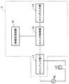
図1は、本発明の一実施形態に係る無線送信装置と、この無線送信装置から送信された無線信号を受信する無線受信装置とを備えた無線通信システムの一例を示す説明図である。図1に示す無線通信システム1は、無線信号を送信する無線送信装置2と、無線信号に応じて照明負荷LDを点滅するスイッチ装置として機能する無線受信装置3とを備えている。無線受信装置3は、照明負荷LDと直列接続されて、電源(商用交流電源)ACに接続されている。なお、負荷は、蛍光灯及び蛍光灯電子安定器などの照明負荷LDに限られず、他の照明負荷や、照明負荷以外の負荷であってもよい。
(First embodiment)
FIG. 1 is an explanatory diagram illustrating an example of a wireless communication system including a wireless transmission device according to an embodiment of the present invention and a wireless reception device that receives a wireless signal transmitted from the wireless transmission device. A
また、無線受信装置3の前面には、操作ハンドル10が設けられている。
An operation handle 10 is provided on the front surface of the
図2は、図1に示す無線受信装置3の構成の一例を示すブロック図である。無線受信装置3は、無線受信回路31、スイッチング素子11、スイッチ制御部12、及びスイッチ入力部13を備えている。
FIG. 2 is a block diagram illustrating an example of the configuration of the
スイッチ入力部13は、例えば操作ハンドル10と連動するように配設されたタクトスイッチを用いて構成されている。スイッチング素子11は、例えばトライアック等のスイッチング素子である。スイッチング素子11は、スイッチ制御部12からの制御信号に応じて照明負荷LDへの給電経路を開閉する。
The
スイッチ制御部12は、例えばマイクロコンピュータを用いて構成されている。そして、スイッチ制御部12は、無線送信装置2から送信され、無線受信回路31によって受信された信号、及びスイッチ入力部13から出力されたオン、オフ信号に応じて、スイッチング素子11を開閉させる。
The
図3は、図2に示す無線受信回路31の構成の一例を示すブロック図である。図3に示す無線受信回路31は、受信アンテナRANT、ローノイズアンプLNA、RFフィルタRFF、ミキサMIX(混合部)、IFフィルタIFF(中間周波数フィルタ)、IFアンプIFA、検波器DTC、ベースバンド回路部RBB、自動周波数調整回路AFC(自動周波数調整部)、及び局部発振回路LOを備えている。この場合、受信アンテナRANT、ローノイズアンプLNA、及びRFフィルタRFFが受信部の一例に相当し、検波器DTC及びベースバンド回路部RBBが復調部の一例に相当している。
FIG. 3 is a block diagram showing an example of the configuration of the
そして、スイッチング素子11のオンオフ指示を示す無線信号が、無線送信装置2から送信され、無線受信回路31の受信アンテナRANTで受信される。受信アンテナRANTで受信された高周波の無線信号は、ローノイズアンプLNAで増幅されRFフィルタRFFで不要周波数成分を除去された後、ミキサMIXによって局部発振回路LOから出力される基準発振周波数(局部発振周波数)の出力信号とミキシングされ、IF信号に変換される。
A wireless signal indicating an on / off instruction of the switching
IF信号はIFフィルタIFFにて不要周波数成分を除去された後IFアンプIFAで増幅され、さらに検波器DTCによって周波数−電圧変換された後べースバンド回路部RBBに伝達され、さらにべースバンド回路部RBBでベースバンドに変換された受信データが、スイッチ制御部12へ出力される。
The IF signal is freed of unnecessary frequency components by the IF filter IFF, amplified by the IF amplifier IFA, further frequency-voltage converted by the detector DTC, and then transmitted to the baseband circuit unit RBB, and further the baseband circuit unit RBB. The reception data converted into the baseband in step S is output to the
これにより、スイッチ制御部12によって、無線送信装置2から送信された無線信号に応じて、スイッチング素子11の開閉が行われる。
Thereby, the
ここで、無線送信装置2の基準発振周波数と無線受信回路31の基準発振周波数とが、温度の影響を受けるなどして互いにずれている場合、IF信号のIF周波数が設計値からずれる。このとき、検波器DTCによって周波数−電圧変換された信号も、設計値からずれてしまい、受信感度が低下する。
Here, when the reference oscillation frequency of the
そこで、検波器DTCの出力信号が自動周波数調整回路AFCに入力される。そして、自動周波数調整回路AFCは、局部発振回路LOの局部発振周波数を、無線送信装置100の基準発振周波数に合わせるように調節して、IF周波数を設計値に収束させる。
Therefore, the output signal of the detector DTC is input to the automatic frequency adjustment circuit AFC. Then, the automatic frequency adjustment circuit AFC adjusts the local oscillation frequency of the local oscillation circuit LO to match the reference oscillation frequency of the
図4は、図1に示す無線送信装置2の構成の一例を示すブロック図である。図4に示す無線送信装置2は、送信制御回路TCC、送信RF回路TRF、基準発振器OSC、パワーアンプPA、及び送信アンテナTANTを備えている。
FIG. 4 is a block diagram illustrating an example of the configuration of the
送信制御回路TCCは、例えば所定の演算処理を実行するCPU(Central Processing Unit)と、所定の制御プログラムが記憶されたROM(Read Only Memory)と、データを一時的に記憶するRAM(Random Access Memory)と、これらの周辺回路等とを備えて構成されている。そして、送信制御回路TCCは、例えばROMに記憶された制御プログラムを実行することにより、ビット同期信号送信部21(第1送信部)、フレーム同期信号送信部22、及びデータ送信部23として機能する。
The transmission control circuit TCC includes, for example, a CPU (Central Processing Unit) that executes predetermined arithmetic processing, a ROM (Read Only Memory) that stores a predetermined control program, and a RAM (Random Access Memory) that temporarily stores data. ) And these peripheral circuits and the like. The transmission control circuit TCC functions as the bit synchronization signal transmission unit 21 (first transmission unit), the frame synchronization
なお、送信制御回路TCCは、CPUを用いる例に限られず、例えばステートマシンや論理回路等を用いて構成されていてもよい。 Note that the transmission control circuit TCC is not limited to an example using a CPU, and may be configured using, for example, a state machine or a logic circuit.
ビット同期信号送信部21は、送信RF回路TRFへ、送信しようとする符号列を示す信号S1と、搬送波周波数からの周波数偏移量を指示する信号S2とを送信RF回路TRFへ送信することにより、送信RF回路TRFによって、搬送波周波数からの周波数偏移量が所定の第1偏移量fDEV1である無線信号を用いてビット同期を取るためのビット同期符号列(第1設定符号列)の少なくとも一部を、送信させる。
The bit synchronization
フレーム同期信号送信部22は、ビット同期信号送信部21によりビット同期符号列が送信された後、信号S1,S2を送信RF回路TRFへ送信することにより、送信RF回路TRFによって、フレーム同期をとるためのフレーム同期符号列を送信させる。
After the bit synchronization code string is transmitted by the bit synchronization
データ送信部23は、フレーム同期信号送信部22によりフレーム同期符号列が送信された後、信号S1,S2を送信RF回路TRFへ送信することにより、送信RF回路TRFによって、搬送波周波数からの周波数偏移量が設定偏移量fDEVSである無線信号を用いてデータを表すデータ符号列を送信させる。
After the frame synchronization code string is transmitted by the frame synchronization
ここで、第1偏移量fDEV1は、データ符号列の送信に用いられる設定偏移量fDEVSより小さな偏移量に設定されている。 Here, the first deviation amount fDEV1 is set to a deviation amount smaller than the set deviation amount fDEVS used for transmitting the data code string.
基準発振器OSCは、例えば水晶発振器を用いて構成されており、FM変調に用いられる基準発振周波数の発振信号を送信RF回路TRFへ出力する。 The reference oscillator OSC is configured by using, for example, a crystal oscillator, and outputs an oscillation signal having a reference oscillation frequency used for FM modulation to the transmission RF circuit TRF.
送信RF回路TRFは、送信制御回路TCCから出力された符号列を示す信号S1を、基準発振器OSCから出力された発振信号に基づいてFSK変調し、その変調信号をパワーアンプPAに送出する。また、送信RF回路TRFは、符号列を変調する際の周波数偏移量を、送信制御回路TCCから出力された信号S2に応じて設定するようになっている。 The transmission RF circuit TRF subjects the signal S1 indicating the code string output from the transmission control circuit TCC to FSK modulation based on the oscillation signal output from the reference oscillator OSC, and sends the modulated signal to the power amplifier PA. Further, the transmission RF circuit TRF sets the frequency shift amount when the code string is modulated in accordance with the signal S2 output from the transmission control circuit TCC.
パワーアンプPAは変調信号を増幅し、送信アンテナTANTに伝達する。そうすると、送信アンテナTANTから空間に無線信号が放射される。 The power amplifier PA amplifies the modulation signal and transmits it to the transmission antenna TANT. Then, a radio signal is radiated from the transmission antenna TANT to the space.
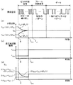
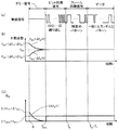
図5は、図1に示す無線通信システム1の動作の一例を説明するための説明図である。図5(a)は無線送信装置2から送信される無線信号を示し、図5(b)はその無線信号が無線受信装置3によって受信された場合にミキサMIXからIFフィルタIFFへ出力されるIF信号の周波数の取り得る範囲(上限と下限)を示し、図5(c)は無線送信装置2におけるFSK変調の周波数偏移量を示し、図5(d)は無線送信装置2におけるIFフィルタIFFで必要となる通過帯域幅BIFを示している。また、図5(a)〜図5(d)の横軸は、自動周波数調整回路AFCによる自動周波数調整の開始からの経過時間tを示している。
FIG. 5 is an explanatory diagram for explaining an example of the operation of the
まず、時間t=0において、無線送信装置2で例えば送信制御回路TCCに接続された図略の人体センサによって人が検知される等して送信トリガが発生する。このような送信トリガが発生すると、ビット同期信号送信部21は、信号S1,S2を出力して、送信RF回路TRFから、周波数偏移fDEVが第1偏移量fDEV1に設定されたビット同期信号を、無線受信回路31の自動周波数調整回路AFCが自動周波数調整を実行するために必要となる時間として予め設定された調整時間TAFCの間、送信させる。
First, at time t = 0, a transmission trigger is generated when a person is detected by, for example, a human sensor (not shown) connected to the transmission control circuit TCC in the
そして、このビット同期信号が無線受信装置3によって受信されると、自動周波数調整回路AFCによる局部発振回路LOの発振周波数の自動調整が開始される(時間t=0)。ここで、無線受信装置3におけるIF周波数の設計値をfIF0、時間tにおけるIF周波数の設計値からのずれの絶対値の最大値を△fIF(t)とすると、自動周波数調整が開始されるとき(t=0)のずれの絶対値の最大値△fIF(0)は、△fTX+△fRXとなる。
When this bit synchronization signal is received by the
すなわち、時間t=0において、IF周波数は、fIF0−(△fTX+△fRX)〜fIF0+(△fTX+△fRX)の範囲となる。このとき、IFフィルタIFFは、この周波数範囲を通過させる必要があるから、時間t=0において必要な通過帯域幅BIFは、式(3)から、下記の式(5)で示される(図5(d))。 That is, at time t = 0, the IF frequency is in the range of f IF0 − (Δf TX + Δf RX ) to f IF0 + (Δf TX + Δf RX ). At this time, since the IF filter IFF needs to pass through this frequency range, the required pass bandwidth B IF at time t = 0 is expressed by the following equation (5) from equation (3) (FIG. 5). 5 (d)).
BIF≧2×(fMOD+fDEV1+△fTX+△fRX) (t=0の場合)・・・(5)
そして、自動周波数調整回路AFCによる自動周波数調整の実行と共に(時間tの経過と共に)、局部発振回路LOから出力される発振信号の周波数が調整されて、自動周波数調整を実行するために必要となる時間である調整時間TAFCの経過後、△fIF(t)は略「0」に収束する。
B IF ≧ 2 × (f MOD + f DEV1 + Δf TX + Δf RX ) (when t = 0) (5)
Then, along with the execution of the automatic frequency adjustment by the automatic frequency adjustment circuit AFC (with the elapse of time t), the frequency of the oscillation signal output from the local oscillation circuit LO is adjusted, and is necessary for executing the automatic frequency adjustment. after the lapse of the adjustment time T AFC is the time, △ f IF (t) is converged to substantially "0".
ここで、ビット同期信号の符号長は、ビット同期信号を送信するのにかかる時間であるビット送信時間TBが、調整時間TAFCより長くなるように予め設定されている。 Here, the code length of the bit synchronization signal, a bit synchronous signal bit transmission time T B is the time taken to transmit a is previously set to be longer than the adjustment time T AFC.
時間tが、0<t<TAFCの期間において、IFフィルタIFFに要求される通過帯域幅BIFは、図5(d)に示すように、下記の式(6)で示される。 As shown in FIG. 5 (d), the pass bandwidth B IF required for the IF filter IFF is expressed by the following equation (6) during the time t is 0 <t <T AFC .
BIF≧2×(fMOD+fDEV1+△fIF(t)) (0<t<TAFCの場合)・・・(6)
そして、ビット同期信号の送信開始から調整時間TAFCが経過すると、ビット同期信号送信部21は、図5(c)に示すように、周波数偏移fDEVを設定偏移量fDEVSに変更する。そうすると、ビット送信時間TBまでの間、周波数偏移fDEVが設定偏移量fDEVSにされたビット同期信号が、無線送信装置2から無線受信装置3へ送信される。
B IF ≧ 2 × (f MOD + f DEV1 + Δf IF (t)) (0 <t <T AFC ) (6)
When the adjustment time T AFC elapses from the start of transmission of the bit synchronization signal, the bit synchronization
その結果、調整時間TAFCが経過した後は、△fIF(t)≒0、fDEV=fDEVSであるから、時間tが、t≧TAFCの期間において、IFフィルタIFFに要求される通過帯域幅BIFは、図5(d)に示すように、下記の式(7)で示される。 As a result, after the adjustment time T AFC has elapsed, Δf IF (t) ≈0 and f DEV = f DEVS , so the time t is required for the IF filter IFF in the period of t ≧ T AFC. The passband width B IF is represented by the following equation (7) as shown in FIG.
BIF≧2×(fMOD+fDEVS) (t≧TAFCの場合)・・・(7)
ビット送信時間TBが経過すると、フレーム同期信号送信部22は、信号S1,S2を出力して、送信RF回路TRFから、周波数偏移fDEVが設定偏移量fDEVSに設定されたフレーム同期信号を送信させる。
B IF ≧ 2 × (f MOD + f DEVS ) (when t ≧ T AFC ) (7)
When the bit transmission time T B has elapsed, the frame
そして、フレーム同期信号の送信が終わると、データ送信部23は、信号S1,S2を出力して、送信RF回路TRFから、周波数偏移fDEVが設定偏移量fDEVSに設定されたデータ信号を送信させる。この場合、データ信号は、例えばスイッチ制御部12にスイッチング素子11のオン、オフを指示する符号列を表しており、一般的にランダムな符号パターンになっている。
When the transmission of the frame synchronization signal ends, the
ここで、上述したように、高速な通信速度と高い通信信頼性を両立させるためには周波数偏移fDEVを大きくする必要がある。しかしながら、同一の通信速度かつ同一の周波数偏移の場合において、受信されるデータがランダム信号であるデータ信号の場合と1010・・・の繰り返しのビット同期信号の場合を比較すると、後者の方が信号に規則性があることによって符号間干渉(Intersymbol interference)が少ないために受信感度がよくなる。 Here, as described above, in order to achieve both high communication speed and high communication reliability, it is necessary to increase the frequency shift fDEV . However, in the case of the same communication speed and the same frequency shift, when comparing the case where the received data is a random signal and the case of repeated bit synchronization signals of 1010. Due to the regularity of the signal, the reception sensitivity is improved because there is less intersymbol interference.
すなわち、規則性のあるビット同期信号の区間において、ランダムなデータ信号の区間より周波数偏移fDEVを小さい値にしても、データ信号の区間と同程度の受信感度を得ることが可能である。よって、データ信号の区間において所望の受信感度を得られるように決定した周波数偏移fDEVを設定偏移量fDEVSとすると、ビット同期信号の区間においてデータ信号の区間と同等の受信感度を得られ、かつ設定偏移量fDEVSより小さい条件を満たす第1偏移量fDEV1が存在する。第1偏移量fDEV1としては、このような条件を満たす第1偏移量fDEV1が予め設定されている。 That is, even if the frequency deviation f DEV is set to a smaller value in the regular bit synchronization signal section than in the random data signal section, it is possible to obtain reception sensitivity comparable to that in the data signal section. Therefore, assuming that the frequency deviation f DEV determined so as to obtain a desired reception sensitivity in the data signal section is the set deviation amount f DEVS , a reception sensitivity equivalent to the data signal section is obtained in the bit synchronization signal section. And a first deviation amount f DEV1 that satisfies a condition smaller than the set deviation amount f DEVS exists. The first shift amount f DEV1, such condition is satisfied first shift amount f DEV1 is set in advance.
そして、無線信号の全体を通じて、これを受信するためにIFフィルタIFFに要求される通過帯域幅BIFは、式(5)及び式(6)から、2×(fMOD+fDEV1+△fTX+△fRX)と、2×(fMOD+fDEVS)とのうちいずれか大きいほうになる(図5(d)では前者の方が大きい例を示している)。とくに、2×(fMOD+fDEV1+△fTX+△fRX)=2×(fMOD+fDEVS)となるように、第1偏移量fDEV1と設定偏移量fDEVSとを設定すると、IFフィルタIFFの通過帯域幅を最も効率的に利用することができる。 Then, the pass bandwidth B IF required for the IF filter IFF to receive the entire wireless signal is expressed by 2 × (f MOD + f DEV1 + Δf TX from Equation (5) and Equation (6). + Δf RX ) or 2 × (f MOD + f DEVS ), whichever is greater (FIG. 5D shows an example where the former is larger). In particular, 2 × (f MOD + f DEV1 + △ f TX + △ f RX) = a so that 2 × (f MOD + f DEVS ), by setting the set shift amount f DEVS the first shift amount f DEV1 The pass bandwidth of the IF filter IFF can be used most efficiently.
一方、図17に示す背景技術では、周波数偏移fDEVがデータ送信時と同じ設定偏移量fDEVSに固定されるため、IFフィルタ115に要求される通過帯域幅は、式(3)からBIF≧2×(fMOD+fDEVS+△fTX+△fRX)となる。そうすると、IFフィルタIFFに要求される通過帯域幅BIFは、2×(fMOD+fDEV1+△fTX+△fRX)と、2×(fMOD+fDEVS)とのうちいずれであったとしても、2×(fMOD+fDEVS+△fTX+△fRX)より小さくなる。
On the other hand, in the background art shown in FIG. 17, since the frequency shift f DEV is fixed to the same set shift amount f DEVS as at the time of data transmission, the pass bandwidth required for the
従って、IFフィルタIFFに要求される通過帯域幅BIFを、下記の式(8)を満たす値に設定することが可能となる。 Therefore, the pass bandwidth B IF required for the IF filter IFF can be set to a value satisfying the following equation (8).
BIF<2×(fMOD+fDEVS+△fTX+△fRX) ・・・(8)
そして、IFフィルタIFFに要求される通過帯域幅BIFを、式(8)を満たすように設定することで、式(4)から、図17に示す背景技術よりも、通過帯域幅BIFを狭くして、無線受信回路31の受信感度SSを向上する(小さくする)ことができる。
B IF <2 × (f MOD + f DEVS + Δf TX + Δf RX ) (8)
Then, the pass bandwidth B IF required for the IF filter IFF, by setting so as to satisfy the equation (8), from equation (4), than the background art shown in FIG. 17, the pass band width B IF The reception sensitivity SS of the
なお、本実施形態では、無線送信装置2と無線受信装置3とがそれぞれ1台の無線通信システムを示したが、無線送信装置2と無線受信装置3とのいずれか一方もしくは両方が複数台からなる無線通信システムであってもよい。
In the present embodiment, the
以上のように構成された無線通信システム1は、ダミー信号を用いることなく無線受信回路31の受信感度SSを向上する(小さくする)ことができるので、ダミー信号により通信時間が増大するおそれを低減しつつ、無線受信装置におけるIFフィルタの通過帯域幅を狭くすることができる。
Since the
なお、ビット同期信号送信部21は、調整時間TAFCのタイミングで周波数偏移fDEVを設定偏移量fDEVSに変更する例を示したが、ビット同期信号送信部21は、図6に示すように、ビット送信時間TBのタイミングで周波数偏移fDEVを設定偏移量fDEVSに変更するようにしてもよい。
The bit
この場合、ビット同期信号送信部21は、調整時間TAFCを計時して、ビット同期信号の送信途中で周波数偏移量を切り替える必要がないので、ビット同期信号送信部21の構成を簡素化することが容易となる。
In this case, bit synchronization
(第2実施形態)
次に、本発明の第2実施形態に係る無線通信システムについて説明する。第2実施形態に係る無線通信システムは、第1実施形態に係る無線通信システムとは、無線送信装置2の代わりに無線送信装置2aを備える点で異なる。無線送信装置2aは、無線送信装置2と同様、図4で示される。
(Second Embodiment)
Next, a radio communication system according to the second embodiment of the present invention will be described. The wireless communication system according to the second embodiment is different from the wireless communication system according to the first embodiment in that a
図4に示す無線送信装置2aは、無線送信装置2とは、送信制御回路TCCaにおけるビット同期信号送信部21a、フレーム同期信号送信部22a(第2送信部)の動作が異なる。
The
ビット同期信号送信部21aは、送信RF回路TRFへ、送信しようとする符号列を示す信号S1と、搬送波周波数からの周波数偏移量を指示する信号S2とを送信RF回路TRFへ送信することにより、送信RF回路TRFによって、搬送波周波数からの周波数偏移量が所定の第1偏移量fDEV1である無線信号を用いてビット同期を取るためのビット同期符号列(第1設定符号列)の全部を送信させる。 The bit synchronization signal transmission unit 21a transmits, to the transmission RF circuit TRF, a signal S1 indicating a code string to be transmitted and a signal S2 instructing a frequency shift amount from the carrier frequency to the transmission RF circuit TRF. The transmission RF circuit TRF generates a bit synchronization code string (first setting code string) for bit synchronization using a radio signal whose frequency deviation from the carrier frequency is a predetermined first deviation f DEV1 . Send everything.
ここで、ビット同期信号を送信するのにかかるビット送信時間TBは、調整時間TAFCより短い時間に設定されている。 Here, the bit transmission time T B it takes to transmit a bit synchronous signal is set to shorter than the adjustment time T AFC time.
フレーム同期信号送信部22aは、ビット同期信号送信部21によりビット同期符号列が送信された後、信号S1,S2を送信RF回路TRFへ送信することにより、送信RF回路TRFによって、搬送波周波数からの周波数偏移量が第2偏移量fDEV2である無線信号を用いてフレーム同期信号を送信させる。
After the bit synchronization code string is transmitted by the bit synchronization
ここで、第2偏移量fDEV2は、第1偏移量fDEV1より大きく、設定偏移量fDEVSより小さい値に設定されている。 Here, the second deviation amount f DEV2 is set to a value larger than the first deviation amount f DEV1 and smaller than the set deviation amount f DEVS .
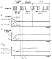
その他の構成は図4に示す無線送信装置2と同様であるのでその説明を省略し、以下本実施形態の動作について説明する。図7は、図4に示す第2実施形態に係る無線送信装置2aと、無線受信装置3とを用いた無線通信システムの動作の一例を説明するための説明図である。
The other configuration is the same as that of the
まず、時間t=0において、送信トリガが発生すると、ビット同期信号送信部21aは、信号S1,S2を出力して、送信RF回路TRFから、周波数偏移fDEVが第1偏移量fDEV1に設定されたビット同期信号を送信させる。 First, when a transmission trigger occurs at time t = 0, the bit synchronization signal transmission unit 21a outputs signals S1 and S2, and the frequency deviation f DEV is changed from the transmission RF circuit TRF to the first deviation amount f DEV1. The bit synchronization signal set to is transmitted.
そして、ビット送信時間TBが経過すると、フレーム同期信号送信部22aは、信号S1,S2を出力して、送信RF回路TRFから、周波数偏移fDEVが第2偏移量fDEV2に設定されたフレーム同期信号を送信させる。 When the elapse of bit transmission time T B, the frame synchronization signal transmitting section 22a outputs a signal S1, S2, from the transmission RF circuit TRF, frequency shift f DEV is set in the second shift amount f DEV2 The frame synchronization signal is transmitted.
ここで、フレーム同期信号を送信するのにかかる時間であるフレーム送信時間TFと、ビット送信時間TBとの合計は、調整時間TAFCより長くなるように設定されている。すなわち、TB<TAFC≦TB+TFとなるように、ビット送信時間TB、フレーム送信時間TF、及び調整時間TAFCが予め設定されている。 Here, the frame transmission time T F is the time taken to transmit a frame synchronizing signal, the total of the bit transmission time T B is set to be longer than the adjustment time T AFC. That is, the bit transmission time T B , the frame transmission time T F , and the adjustment time T AFC are set in advance so that T B <T AFC ≦ T B + TF .
そして、上述のように、ビット同期信号の区間においては符号間干渉がないため、周波数偏移をデータ信号の区間よりも小さい値にしてもデータ信号の区間と同程度の受信感度を得ることが可能である。フレーム同期信号においても、同一符号の最大連続数を制限し、フレーム同期信号の区間内で0と1の出現回数をほぼ同じにすることにより、ランダムなデータ信号の区間と比べて符号間干渉を小さくすることができる。 As described above, since there is no intersymbol interference in the bit synchronization signal section, even if the frequency shift is set to a value smaller than that of the data signal section, it is possible to obtain reception sensitivity comparable to that of the data signal section. Is possible. Even in the frame synchronization signal, the maximum number of consecutive identical codes is limited, and the number of occurrences of 0 and 1 in the frame synchronization signal interval is almost the same, thereby reducing intersymbol interference compared to the random data signal interval. Can be small.
従って、フレーム同期信号の区間においてビット同期信号の区間やデータ信号の区間と同等の受信感度を得られ、かつ第1偏移量fDEV1より大きく、設定偏移量fDEVSより小さい条件を満たす第2偏移量fDEV2が存在する。第2偏移量fDEV2としては、このような条件を満たす第2偏移量fDEV2が予め設定されている。 Accordingly, in the frame synchronization signal section, the receiving sensitivity equivalent to the bit synchronization signal section and the data signal section can be obtained, and the condition satisfying the condition that is larger than the first deviation amount f DEV1 and smaller than the set deviation amount f DEVS is satisfied. There is a 2 deviation amount fDEV2 . The second shift amount f DEV2, such conditions are satisfied second shift amount f DEV2 is set in advance.
これにより、無線送信装置2aは、0≦t<TBの期間においては周波数偏移fDEVを第1偏移量fDEV1とし、TB≦t<TB+TFの期間においては周波数偏移fDEVを第2偏移量fDEV2とし、TB+TF≦tの期間においては周波数偏移fDEVを設定偏移量fDEVSとする。
As a result, the
そうすると、無線受信回路31のIFフィルタIFFに要求される通過帯域幅BIFは、式(3)に基づき以下の式(9)〜(12)で与えられる。
Then, the pass bandwidth B IF required for the IF filter IFF of the
BIF≧2×(fMOD+fDEV1+△fTX+△fRX) (t=0の場合) ・・・(9)
BIF≧2×(fMOD+fDEV1+△fIF(t)) (0<t<TBの場合) ・・・(10)
BIF≧2×(fMOD+fDEV2+△fIF(t)) (TB≦t<TB+TFの場合) ・・・(11)
BIF≧2×(fMOD+fDEVS) (t≧TB+TFの場合) ・・・(12)。
B IF ≧ 2 × (f MOD + f DEV1 + Δf TX + Δf RX ) (when t = 0) (9)
B IF ≧ 2 × (f MOD + f DEV1 + Δf IF (t)) (when 0 <t <T B ) (10)
B IF ≧ 2 × (f MOD + f DEV2 + Δf IF (t)) (when T B ≦ t <T B + TF ) (11)
B IF ≧ 2 × (f MOD + f DEVS ) (when t ≧ T B + TF ) (12)
そして、無線信号の全体を通じて、これを受信するためにIFフィルタIFFに要求される通過帯域幅BIFは、式(9)〜(12)から、2×(fMOD+fDEV1+△fTX+△fRX)と、2×(fMOD+fDEV2+△fIF(TB))と、2×(fMOD+fDEVS)とのうちの最大値になる(図7(d)では、2×(fMOD+fDEV1+△fTX+△fRX)が最も大きい例を示している)。 Then, the pass bandwidth B IF required for the IF filter IFF to receive the entire wireless signal is expressed by 2 × (f MOD + f DEV1 + Δf TX + from Equations (9) to (12). Δf RX ), 2 × (f MOD + f DEV2 + Δf IF (T B )), and 2 × (f MOD + f DEVS ) (2 × in FIG. 7D) (F MOD + f DEV1 + Δf TX + Δf RX ) is the largest example).
とくに、2×(fMOD+fDEV1+△fTX+△fRX)=2×(fMOD+fDEV2+△fIF(TB))=2×(fMOD+fDEVS)となるように、第1偏移量fDEV1、第2偏移量fDEV2、及び設定偏移量fDEVSを設定すると、IFフィルタIFFの通過帯域幅を最も効率的に利用することができる。 In particular, 2 × (f MOD + f DEV1 + Δf TX + Δf RX ) = 2 × (f MOD + f DEV2 + Δf IF (T B )) = 2 × (f MOD + f DEVS ) When the 1st deviation amount f DEV1 , the second deviation amount f DEV2 , and the set deviation amount f DEVS are set, the pass bandwidth of the IF filter IFF can be used most efficiently.
一方、図17に示す背景技術では、IFフィルタ115に要求される通過帯域幅は、上述したように、BIF≧2×(fMOD+fDEVS+△fTX+△fRX)となる。そうすると、IFフィルタIFFに要求される通過帯域幅BIFは、2×(fMOD+fDEV1+△fTX+△fRX)と、2×(fMOD+fDEV2+△fIF(TB))と、2×(fMOD+fDEVS)とのうちいずれが最大であったとしても、2×(fMOD+fDEVS+△fTX+△fRX)より小さくなる。
On the other hand, in the background art shown in FIG. 17, the pass bandwidth required for the
従って、IFフィルタIFFに要求される通過帯域幅BIFを、上記式(8)を満たす値に設定することが可能となる。そして、IFフィルタIFFに要求される通過帯域幅BIFを、式(8)を満たすように設定することで、式(4)から、図17に示す背景技術よりも、無線受信回路31の受信感度SSを向上する(小さくする)ことができる。
Therefore, the pass bandwidth B IF required for the IF filter IFF can be set to a value satisfying the above equation (8). Then, by setting the pass bandwidth B IF required for the IF filter IFF so as to satisfy the equation (8), the reception of the
なお、フレーム同期信号送信部22aは、フレーム同期信号の区間全体について周波数偏移fDEVを第2偏移量fDEV2にする例を示したが、調整時間TAFCのタイミングで周波数偏移fDEVを第2偏移量fDEV2から設定偏移量fDEVSに変更するようにしてもよい。 Note that the frame synchronization signal transmission unit 22a has shown the example in which the frequency shift f DEV is set to the second shift amount f DEV2 for the entire section of the frame synchronization signal, but the frequency shift f DEV at the timing of the adjustment time T AFC. May be changed from the second deviation amount fDEV2 to the set deviation amount fDEVS .
また、本実施形態では、無線送信装置2aと無線受信装置3とがそれぞれ1台の無線通信システムを示したが、無線送信装置2aと無線受信装置3とのいずれか一方もしくは両方が複数台からなる無線通信システムであってもよい。
Further, in the present embodiment, the
以上のように構成された無線通信システムは、ビット送信時間TBを、調整時間TAFCより短い時間にすることができるので、通信時間短縮のためにビット同期信号の長さを短くすることが容易である。 Or a wireless communication system configured as described, the bit transmission time T B, it is possible to shorter adjustment time T AFC time, is possible to shorten the length of the bit synchronization signal in order to shorten communication time Easy.
また、自動周波数調整回路部AFCの応答が早すぎると、データ区間において同一符号が連続した場合にこの符号部分で周波数調整が実行されてしまい、IF周波数がずれてしまうおそれがある。そこで、通信プロトコル上発生し得る同一符号の最大連続時に、IF周波数がずれてしまわない程度に、自動周波数調整回路部AFCの応答時間が長く(時定数が大きく)する必要がある。ここで、無線送信装置2aは、図7に示すように、調整時間TAFCをビット送信時間TBより長い時間に設定することができるので、自動周波数調整回路部AFCの応答時間を調整するための自由度を大きくすることができる。
Further, if the response of the automatic frequency adjustment circuit unit AFC is too early, when the same code continues in the data section, the frequency adjustment is executed in this code portion, and the IF frequency may be shifted. Therefore, the response time of the automatic frequency adjustment circuit unit AFC needs to be long (the time constant is large) so that the IF frequency does not deviate when the same code that can occur in the communication protocol is maximum. The
そして、ダミー信号を用いることなく無線受信回路31の受信感度SSを向上する(小さくする)ことができるので、ダミー信号により通信時間が増大するおそれを低減しつつ、無線受信装置におけるIFフィルタの通過帯域幅を狭くすることができる。
Since the reception sensitivity SS of the
(第3実施形態)
次に、本発明の第3実施形態に係る無線通信システムについて説明する。第3実施形態に係る無線通信システムは、第1実施形態に係る無線通信システムとは、無線送信装置2の代わりに無線送信装置2bを備える点で異なる。無線送信装置2bは、無線送信装置2と同様、図4で示される。
(Third embodiment)
Next, a radio communication system according to the third embodiment of the present invention will be described. The wireless communication system according to the third embodiment is different from the wireless communication system according to the first embodiment in that a
図4に示す無線送信装置2bは、無線送信装置2とは、送信制御回路TCCbにおけるビット同期信号送信部21bの動作が異なる。なお、フレーム同期信号送信部22bは、フレーム同期信号送信部22と同様に動作する。
4 differs from the
ビット同期信号送信部21bは、信号S1,S2を送信RF回路TRFへ送信することにより、送信RF回路TRFによって、周波数偏移fDEVを、第1偏移量fDEV1から設定偏移量fDEVSに向かって徐々に増大させつつビット同期信号を送信させる。このとき、ビット同期信号送信部21bは、例えば、時間t=0から調整時間TAFCの経過後に、周波数偏移fDEVが設定偏移量fDEVSになるように、周波数偏移fDEVを増大させるようになっている。 By transmitting the signals S1 and S2 to the transmission RF circuit TRF, the bit synchronization signal transmission unit 21b changes the frequency deviation f DEV from the first deviation amount f DEV1 to the set deviation amount f DEVS by the transmission RF circuit TRF. The bit synchronization signal is transmitted while being gradually increased toward. At this time, the bit synchronization signal transmission section 21b, for example, after the elapse of the adjustment time T AFC from the time t = 0, so that the frequency shift f DEV is set shift amount f DEVS, increasing the frequency deviation f DEV It is supposed to let you.
その他の構成は図4に示す無線送信装置2と同様であるのでその説明を省略し、以下本実施形態の動作について説明する。図8は、図4に示す第3実施形態に係る無線送信装置2bと、無線受信装置3とを用いた無線通信システムの動作の一例を説明するための説明図である。
Since the other configuration is the same as that of the
図8(c)に示すように、時間tにおける周波数偏移fDEVを周波数偏移fDEV(t)とすると、時間t=0のときfDEV(0)=fDEV1、時間t=TAFCのときfDEV(TAFC)=fDEVSとなる。 As shown in FIG. 8C, when the frequency deviation f DEV at time t is defined as frequency deviation f DEV (t), when time t = 0, f DEV (0) = f DEV1 , time t = T AFC Then, f DEV (T AFC ) = f DEVS .
そして、0<t<TAFCの区間において、自動周波数調整回路AFCの動作により、△fIF(t)は徐々に減少して0に収束していくため、IFフィルタIFFに要求される通過帯域幅BIFを増加させることなく周波数偏移fDEV(t)を増加させていくことができる。 In the interval of 0 <t <T AFC , Δf IF (t) gradually decreases and converges to 0 by the operation of the automatic frequency adjustment circuit AFC, so that the pass band required for the IF filter IFF The frequency shift f DEV (t) can be increased without increasing the width B IF .
そこで、ビット同期信号送信部21bは、下記の式(13)を満足するように、周波数偏移fDEVを徐々に増大させることで、調整時間TAFCが経過するまで周波数偏移fDEVが第1偏移量fDEV1に固定されている場合と比べてビット同期信号の受信感度を高めることが可能となる。 Therefore, the bit synchronous signal transmission unit 21b, so as to satisfy the equation (13) below, by increasing gradually the frequency shift f DEV, frequency deviation f DEV to adjust time T AFC has passed the The reception sensitivity of the bit synchronization signal can be increased as compared with the case where the shift amount is fixed at fDEV1 .
2×(fMOD+fDEV(t)+△fIF(t))≦2×(fMOD+fDEV1+△fTX+△fRX) ・・・(13)
なお、本実施形態では、無線送信装置2bと無線受信装置3とがそれぞれ1台の無線通信システムを示したが、無線送信装置2bと無線受信装置3とのいずれか一方もしくは両方が複数台からなる無線通信システムであってもよい。
2 × (f MOD + f DEV (t) + Δf IF (t)) ≦ 2 × (f MOD + f DEV1 + Δf TX + Δf RX ) (13)
In the present embodiment, the
以上のように構成された無線通信システムは、周波数偏移fDEV(t)を連続的に変化させることにより、ビット同期信号の受信感度を高めることができる。 The wireless communication system configured as described above can increase the reception sensitivity of the bit synchronization signal by continuously changing the frequency shift f DEV (t).
(第4実施形態)
次に、本発明の第4実施形態に係る無線通信システムについて説明する。第4実施形態に係る無線通信システムは、第2実施形態に係る無線通信システムとは、無線送信装置2aの代わりに無線送信装置2cを備える点で異なる。無線送信装置2cは、無線送信装置2aと同様、図4で示される。
(Fourth embodiment)
Next, a radio communication system according to the fourth embodiment of the present invention is described. The wireless communication system according to the fourth embodiment is different from the wireless communication system according to the second embodiment in that a
図4に示す無線送信装置2cは、図7に動作を示す無線送信装置2aとは、送信制御回路TCCcにおけるビット同期信号送信部21c、及びフレーム同期信号送信部22cの動作が異なる。
The
ビット同期信号送信部21cは、信号S1,S2を送信RF回路TRFへ送信することにより、送信RF回路TRFによって、周波数偏移fDEVを、第1偏移量fDEV1から第2偏移量fDEV2に向かって徐々に増大させつつビット同期信号を送信させる。このとき、ビット同期信号送信部21cは、例えば、時間t=0からビット送信時間TBの経過後に、周波数偏移fDEVが第2偏移量fDEV2になるように、周波数偏移fDEVを増大させるようになっている。 The bit synchronization signal transmission unit 21c transmits the signals S1 and S2 to the transmission RF circuit TRF, so that the transmission RF circuit TRF changes the frequency deviation f DEV from the first deviation amount f DEV1 to the second deviation amount f. The bit synchronization signal is transmitted while gradually increasing toward DEV2 . At this time, the bit synchronization signal transmission unit 21c, for example, after a bit transmission time T B from the time t = 0, so that the frequency shift f DEV is a second shift amount f DEV2, the frequency shift f DEV Is to increase.
フレーム同期信号送信部22cは、信号S1,S2を送信RF回路TRFへ送信することにより、送信RF回路TRFによって、周波数偏移fDEVを、第2偏移量fDEV2から設定偏移量fDEVSに向かって徐々に増大させつつフレーム同期信号を送信させる。このとき、フレーム同期信号送信部22cは、フレーム同期信号の送信期間内、例えば、時間t=0から調整時間TAFCの経過後に、周波数偏移fDEVが設定偏移量fDEVSになるように、周波数偏移fDEVを増大させるようになっている。 The frame synchronization signal transmission unit 22c transmits the signals S1 and S2 to the transmission RF circuit TRF, so that the transmission RF circuit TRF changes the frequency deviation f DEV from the second deviation amount f DEV2 to the set deviation amount f DEVS. The frame synchronization signal is transmitted while gradually increasing toward. At this time, the frame synchronization signal transmission unit 22c is configured so that the frequency deviation f DEV becomes the set deviation amount f DEVS within the transmission period of the frame synchronization signal, for example, after the adjustment time T AFC has elapsed from time t = 0. The frequency deviation f DEV is increased.
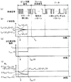
その他の構成は図4に示す無線送信装置2aと同様であるのでその説明を省略し、以下本実施形態の動作について説明する。図9は、図4に示す第4実施形態に係る無線送信装置2cと、無線受信装置3とを用いた無線通信システムの動作の一例を説明するための説明図である。
Since other configurations are the same as those of the
図9(c)に示すように、時間tにおける周波数偏移fDEVを周波数偏移fDEV(t)とすると、時間t=0のときfDEV(0)=fDEV1、時間t=TBのときfDEV(TB)=fDEV2、時間t=TAFCのときfDEV(TAFC)=fDEVSとなる。 As shown in FIG. 9C, when the frequency deviation f DEV at time t is defined as frequency deviation f DEV (t), when time t = 0, f DEV (0) = f DEV1 and time t = T B F DEV (T B ) = f DEV2 , and when time t = T AFC , f DEV (T AFC ) = f DEVS .
そして、0<t<TBの区間において、自動周波数調整回路AFCの動作により、△fIF(t)は徐々に減少していくため、IFフィルタIFFに要求される通過帯域幅BIFを増加させることなく周波数偏移fDEV(t)を増加させていくことができる。 The increase in 0 <t <T B of the section, by the operation of the automatic frequency adjustment circuit AFC, since △ f IF (t) gradually decreases, the passband width B IF required for the IF filter IFF It is possible to increase the frequency shift f DEV (t) without causing the change.
そこで、ビット同期信号送信部21cは、上記式(13)を満足するように、周波数偏移fDEVを徐々に増大させることで、調整時間TAFCやビット送信時間TBが経過するまで周波数偏移fDEVが第1偏移量fDEV1に固定されている場合と比べてビット同期信号の受信感度を高めることが可能となる。 Accordingly, the bit synchronization signal transmission unit 21c, so as to satisfy the above equation (13), by increasing gradually the frequency shift f DEV, frequency polarized until adjustment time T AFC and bit transmission time T B has elapsed shift f DEV is possible to increase the reception sensitivity of the bit synchronization signal as compared with a case that is fixed to the first shift amount f DEV1.
さらに、TB<t<TAFCの区間において、自動周波数調整回路AFCの動作により、△fIF(t)は徐々に減少し、0に収束していくため、IFフィルタIFFに要求される通過帯域幅BIFを増加させることなく周波数偏移fDEV(t)を増加させていくことができる。 Further, in the section of T B <t <T AFC , Δf IF (t) gradually decreases and converges to 0 by the operation of the automatic frequency adjustment circuit AFC, so that the passage required for the IF filter IFF The frequency shift f DEV (t) can be increased without increasing the bandwidth B IF .
そこで、フレーム同期信号送信部22cは、下記の式(14)を満足するように、周波数偏移fDEVを徐々に増大させることで、フレーム同期信号の送信期間において周波数偏移fDEVが第2偏移量fDEV2に固定されている場合と比べてフレーム同期信号の受信感度を高めることが可能となる。 Therefore, the frame synchronization signal transmission unit 22c gradually increases the frequency deviation f DEV so as to satisfy the following equation (14), so that the frequency deviation f DEV is the second during the frame synchronization signal transmission period. The reception sensitivity of the frame synchronization signal can be increased as compared with the case where the deviation amount f DEV2 is fixed.
2×(fMOD+fDEV(t)+△fIF(t))≦2×(fMOD+fDEV2+△fTX+△fRX) ・・・(14)
なお、本実施形態では、無線送信装置2cと無線受信装置3とがそれぞれ1台の無線通信システムを示したが、無線送信装置2cと無線受信装置3とのいずれか一方もしくは両方が複数台からなる無線通信システムであってもよい。
2 × (f MOD + f DEV (t) + Δf IF (t)) ≦ 2 × (f MOD + f DEV2 + Δf TX + Δf RX ) (14)
In the present embodiment, the
以上のように構成された無線通信システムは、ビット同期信号及びフレーム同期信号の送信期間において、周波数偏移fDEV(t)を連続的に変化させることにより、ビット同期信号及びフレーム同期信号の受信感度を高めることができる。 The wireless communication system configured as described above receives the bit synchronization signal and the frame synchronization signal by continuously changing the frequency shift f DEV (t) during the transmission period of the bit synchronization signal and the frame synchronization signal. Sensitivity can be increased.
(第5実施形態)
次に、本発明の第5実施形態に係る無線通信システムについて説明する。第5実施形態に係る無線通信システムは、第1実施形態に係る無線通信システムとは、無線送信装置2の代わりに無線送信装置2dを備える点で異なる。
(Fifth embodiment)
Next, a radio communication system according to the fifth embodiment of the present invention is described. The wireless communication system according to the fifth embodiment is different from the wireless communication system according to the first embodiment in that a
図10は、第5実施形態に係る無線送信装置2dの構成の一例を示すブロック図である。図10に示す無線送信装置2dは、図4に示す無線送信装置2とは、送信制御回路TCCdが無変調信号送信部25(無変調送信部)をさらに備える点で異なる。
FIG. 10 is a block diagram illustrating an example of a configuration of a
無変調信号送信部25は、ビット同期信号送信部21によるビット同期信号の送信が開始される前に、無変調の信号、すなわち搬送波周波数の信号を、ダミー信号として送信RF回路TRFによって送信させる。
The unmodulated
また、無変調信号送信部25によるダミー信号の送信にかかる時間をダミー送信時間TDとすると、ビット同期信号送信部21による第1偏移量fDEV1でのビット同期信号の送信が実行される時間とダミー送信時間TDとの合計が、調整時間TAFC以上に設定されている。また、ダミー送信時間TDは、調整時間TAFCより短くされている。
Further, when the time for transmission of the dummy signal by an unmodulated
その他の構成は図4に示す無線送信装置2と同様であるのでその説明を省略し、以下本実施形態の動作について説明する。図11は、図10に示す無線送信装置2dと、無線受信装置3とを用いた無線通信システムの動作の一例を説明するための説明図である。図11においては、無変調信号送信部25によるダミー信号の開始時を時間t=0としている。
Since the other configuration is the same as that of the
無変調のダミー信号は、変調によるスペクトラムの拡散がないため、無線受信回路31においてダミー信号を受信するためにIFフィルタIFFに要求される通過帯域幅BIFは、2×(△fTX+△fRX)となる。
Since the unmodulated dummy signal has no spectrum spread due to modulation, the pass bandwidth B IF required for the IF filter IFF to receive the dummy signal in the
これにより、無線送信装置2dは、0≦t<TDの期間においては周波数偏移fDEVをゼロとする。そして、無線受信回路31によってこのダミー信号が受信されると、自動周波数調整回路AFCの動作により、△fIF(t)は徐々に減少する。
Thus, the
そして、ダミー送信時間TDが経過してダミー信号の送信が終了すると、ビット同期信号送信部21によるビット同期信号の送信が第1偏移量fDEV1で開始される。
When the transmission of the dummy signal dummy transmission time T D has elapsed is completed, the transmission of the bit synchronization signal by the bit
そうすると、無線受信回路31のIFフィルタIFFに要求される通過帯域幅BIFは、式(3)に基づき以下の式(15)〜(18)で与えられる。
Then, the pass bandwidth B IF required for the IF filter IFF of the
BIF≧2×(△fTX+△fRX) (t=0の場合) ・・・(15)
BIF≧2×△fIF(t) (0<t<TDの場合) ・・・(16)
BIF≧2×(fMOD+fDEV1+△fIF(t)) (TD≦t<TD+TBの場合) ・・・(17)
BIF≧2×(fMOD+fDEVS) (t≧TD+TBの場合) ・・・(18)。
B IF ≧ 2 × (Δf TX + Δf RX ) (when t = 0) (15)
B IF ≧ 2 × △ f IF (t) (0 <t < the case of T D) ··· (16)
B IF ≧ 2 × (f MOD + f DEV1 + Δf IF (t)) (when T D ≦ t <T D + T B ) (17)
B IF ≧ 2 × (f MOD + f DEVS ) (when t ≧ T D + T B ) (18).
そして、無線信号の全体を通じて、これを受信するためにIFフィルタIFFに要求される通過帯域幅BIFは、式(15)〜(18)から、2×(△fTX+△fRX)、2×(fMOD+fDEV1+△fIF(TD))、及び2×(fMOD+fDEVS)のうちの最大値になる(図11(d)では、2×(△fTX+△fRX)が最も大きい例を示している)。 Then, the pass bandwidth B IF required for the IF filter IFF to receive the entire radio signal is expressed by 2 × (Δf TX + Δf RX ), from Equations (15) to (18), 2 × (f MOD + f DEV1 + Δf IF (T D )) and 2 × (f MOD + f DEVS ) (in FIG. 11D, 2 × (Δf TX + Δf RX ) shows the largest example).
特に、2×(△fTX+△fRX)=2×(fMOD+fDEV1+△fIF(TD))=2×(fMOD+fDEVS)となるように、第1偏移量fDEV1、設定偏移量fDEVS、及びダミー送信時間TDを設定すると、IFフィルタIFFの通過帯域幅を最も効率的に利用することができる。 In particular, the first deviation amount f so that 2 × (Δf TX + Δf RX ) = 2 × (f MOD + f DEV1 + Δf IF (T D )) = 2 × (f MOD + f DEVS ) DEV1, setting shift amount f DEVS, and setting the dummy transmission time T D, it is possible to use a passband width of the IF filter IFF most efficiently.
これにより、図18に示す背景技術では、少なくとも調整時間TAFCの間、ダミー信号を送信し続ける必要があったが、図10に示す無線送信装置2dは、ダミー送信時間TDを調整時間TAFCより短くできるので、図18に示す背景技術と比べて、通信時間が増大するおそれを低減しつつ、無線受信回路31におけるIFフィルタIFFの通過帯域幅を狭くすることが容易となる。
Thus, in the background art shown in FIG. 18, for at least the adjustment time T AFC, it has been necessary to continue to transmit a dummy signal, a
なお、本実施形態では、無線送信装置2dと無線受信装置3とがそれぞれ1台の無線通信システムを示したが、無線送信装置2dと無線受信装置3とのいずれか一方もしくは両方が複数台からなる無線通信システムであってもよい。
In the present embodiment, the
また、無線送信装置2a,2b,2cにおける送信制御回路TCCa,TCCb,TCCcに、無変調信号送信部25を設けるようにしてもよい。
Further, the unmodulated
(第6実施形態)
次に、本発明の第6実施形態に係る無線通信システムについて説明する。第6実施形態に係る無線通信システムは、第5実施形態に係る無線通信システムとは、無線送信装置2dの代わりに無線送信装置2eを備える点で異なる。
(Sixth embodiment)
Next, a radio communication system according to the sixth embodiment of the present invention is described. The wireless communication system according to the sixth embodiment is different from the wireless communication system according to the fifth embodiment in that a
図12は、第6実施形態に係る無線送信装置2eの構成の一例を示すブロック図である。図12に示す無線送信装置2eは、図10に示す無線送信装置2dとは、温度センサTS(温度検出部)をさらに備える点、送信制御回路TCCdがさらに偏移量設定部26を備える点で異なる。また、無変調信号送信部25eの動作が異なる。
FIG. 12 is a block diagram illustrating an example of a configuration of the
温度センサTSは、無線送信装置2dの温度、特に基準発振器OSCの温度を検出する温度センサである。
The temperature sensor TS is a temperature sensor that detects the temperature of the
無変調信号送信部25eは、温度センサTSによって検出された温度に応じて、ダミー送信時間TDの長さを設定する。 Unmodulated signal transmitting unit 25e, in response to the temperature detected by the temperature sensor TS, sets the length of the dummy transmission time T D.
偏移量設定部26は、温度センサTSによって検出された温度に応じて、第1偏移量fDEV1、及び設定偏移量fDEVSを設定する。なお、設定偏移量fDEVSは、固定値であってもよい。
The deviation
その他の構成は図10に示す無線送信装置2dと同様であるのでその説明を省略し、以下本実施形態の動作について説明する。図13は、図12に示す無線送信装置2eと、無線受信装置3とを用いた無線通信システムの動作の一例を説明するための説明図である。図13においては、無変調信号送信部25eによるダミー信号の開始時を時間t=0としている。
Since the other configuration is the same as that of the
一般に、基準発振器OSCの発振周波数が変動する要因としては、温度の影響が支配的である。したがって、温度センサTSによって検出された基準発振器OSCの温度をXとすると、基準発振周波数偏差△fTXは、温度Xの関数として△fTX(X)と表すことができる。 In general, the influence of temperature is dominant as a factor that fluctuates the oscillation frequency of the reference oscillator OSC. Therefore, when the temperature of the reference oscillator OSC detected by the temperature sensor TS is X, the reference oscillation frequency deviation Δf TX can be expressed as Δf TX (X) as a function of the temperature X.
そこで、偏移量設定部26は、△fTX(X)の絶対値が大きくなるほど(すなわち、基準発振周波数偏差△fTXの絶対値が大きくなる温度ほど)、第1偏移量fDEV1、及び設定偏移量fDEVSを小さくすることで、中間周波数がIFフィルタIFF通過帯域幅BIFに収まるように調節する。また、無変調信号送信部25eは、△fTX(X)の絶対値が大きくなるほど、ダミー送信時間TDを増大することで、自動周波数調整回路AFCによる自動周波数調整に必要な時間を確保するようになっている。
Therefore, the deviation
また、偏移量設定部26及び無変調信号送信部25eは、2×(△fTX(X)+△fRX)=2×(△fTX+△fRX+fMOD+fDEV1)=2×(fMOD+fDEVS)となるように、第1偏移量fDEV1、設定偏移量fDEVS、及びダミー送信時間TDを設定すると、IFフィルタIFFの通過帯域幅を最も効率的に利用することができる。この場合、無変調信号送信部25eは、△fTX又は、予め設定された△fRXの予測値と△fTXとの合計が大きいほど、ダミー送信時間TDを大きくする。
Further, the deviation
ところで、図10に示す無線送信装置2dでは、偏差△fTXが温度の影響を考慮した場合の最大値となっているため、実際には偏差△fTXが小さい温度であっても、偏差△fTXが最大になったときでも中間周波数が通過帯域幅BIFに収まるように、第1偏移量fDEV1が小さな値に設定される。
By the way, in the
一方、図12に示す無線送信装置2eでは、温度の影響を考慮した△fTX(X)に応じて第1偏移量fDEV1が設定されるので、偏差△fTXが小さくなる温度では、その分第1偏移量fDEV1を大きくすることで、通過帯域幅BIFを無駄なく利用することができる。その結果、図10に示す無線送信装置2dよりもビット同期信号の受信感度を向上させることが可能となる。
On the other hand, in the
また、図10に示す無線送信装置2dでは、偏差△fTXが温度の影響を考慮した場合の最大値であっても、自動周波数調整回路AFCが△fIF(t)を略「0」に収束させることができるように、ダミー送信時間TDを設定しておく必要があったので、偏差△fTXが小さくなる温度においても、ダミー送信時間TDを最悪条件に合わせた時間にする必要がある。
In the
一方、図12に示す無線送信装置2eでは、温度の影響を考慮した△fTX(X)に応じて、△fTX(X)が小さくなるほど、ダミー送信時間TDが短くされるので、温度条件がよい場合には、ダミー送信時間TDを短くして無線送信装置2dよりも通信時間を短縮することが可能となる。
On the other hand, in the
(第7実施形態)
次に、本発明の第7実施形態に係る無線通信システムについて説明する。第7実施形態に係る無線通信システムは、第1実施形態に係る無線通信システムとは、無線送信装置2の代わりに無線送信装置2fを備える点で異なる。
(Seventh embodiment)
Next, a radio communication system according to the seventh embodiment of the present invention is described. The wireless communication system according to the seventh embodiment is different from the wireless communication system according to the first embodiment in that a
図14は、本発明の第7実施形態に係る無線送信装置2fの構成の一例を示すブロック図である。図14に示す無線送信装置2fは、図4に示す無線送信装置2とは、温度センサTSをさらに備える点、送信制御回路TCCfがさらに偏移量設定部26を備える点で異なる。
FIG. 14 is a block diagram showing an example of a configuration of a
その他の構成は図4に示す無線送信装置2と同様であるのでその説明を省略し、以下本実施形態の動作について説明する。図15は、図14に示す無線送信装置2fと、無線受信装置3とを用いた無線通信システムの動作の一例を説明するための説明図である。
Since the other configuration is the same as that of the
一般に、基準発振器OSCの発振周波数が変動する要因としては、温度の影響が支配的である。したがって、温度センサTSによって検出された基準発振器OSCの温度をXとすると、基準発振周波数偏差△fTXは、温度Xの関数として△fTX(X)と表すことができる。 In general, the influence of temperature is dominant as a factor that fluctuates the oscillation frequency of the reference oscillator OSC. Therefore, when the temperature of the reference oscillator OSC detected by the temperature sensor TS is X, the reference oscillation frequency deviation Δf TX can be expressed as Δf TX (X) as a function of the temperature X.
そこで、偏移量設定部26は、△fTX(X)が大きくなるほど(すなわち、基準発振周波数偏差△fTXが大きくなる温度ほど)、第1偏移量fDEV1を小さくすることで、中間周波数がIFフィルタIFF通過帯域幅BIFに収まるように調節する。
Therefore, the deviation
ここで、偏移量設定部26は、(△fTX+fDEV1(X))が一定となるように、温度Xのときの第1偏移量fDEV1(X)を設定することで、温度に応じて最適な第1偏移量fDEV1(X)を設定することができる結果、図4に示す無線送信装置2よりも、ビット同期信号の受信感度を向上させることができる。
Here, the deviation
なお、関数は、例えば関数式で表されていてもよく、例えばデータテーブルを用いて表されていてもよい。 Note that the function may be expressed by a functional expression, for example, and may be expressed by using a data table, for example.
1 無線通信システム
2,2a,2b,2c,2d,2e,2f 無線送信装置
3 無線受信装置
10 操作ハンドル
11 スイッチング素子
12 スイッチ制御部
13 スイッチ入力部
21,21a,21b,21c ビット同期信号送信部
22,22a,22b,22c フレーム同期信号送信部
23 データ送信部
25,25e 無変調信号送信部
26 偏移量設定部
31 無線受信回路
BIF 通過帯域幅
AFC 自動周波数調整回路
DTC 検波器
IFA IFアンプ
IFF IFフィルタ
LNA ローノイズアンプ
LO 局部発振回路
MIX ミキサ
OSC 基準発振器
PA パワーアンプ
RANT 受信アンテナ
RBB ベースバンド回路部
RFF RFフィルタ
SS 受信感度
TANT 送信アンテナ
TAFC 調整時間
TB ビット送信時間
TCC,TCCa,TCCb,TCCc,TCCd,TCCe,TCCf 送信制御回路
TD ダミー送信時間
TF フレーム送信時間
TRF 送信制御回路
TS 温度センサ
fDEV 周波数偏移
fDEV1 第1偏移量
fDEV2 第2偏移量
fDEVS 設定偏移量
fMOD 変調周波数
△fTX 基準発振周波数偏差
△fRX 局部発振周波数偏差
DESCRIPTION OF
Claims (12)
前記搬送波周波数からの周波数偏移量が所定の第1偏移量である無線信号を用いて予め設定された規則性を有する第1設定符号列の少なくとも一部を送信する第1偏移信号送信処理を、実行する第1送信部と、
前記第1送信部により前記第1設定符号列が送信された後、前記搬送波周波数からの周波数偏移量が前記第1偏移量より大きい値に設定された設定偏移量である無線信号を用いてデータを表すデータ符号列を送信するデータ送信処理を、実行するデータ送信部と
を備えることを特徴とする無線送信装置。 A wireless transmitter that modulates the frequency of a radio signal by shifting it from a carrier frequency,
First shift signal transmission for transmitting at least a part of a first set code sequence having a regularity set in advance using a radio signal having a frequency shift amount from the carrier frequency being a predetermined first shift amount A first transmission unit for executing processing;
After the first set code string is transmitted by the first transmitter, a radio signal having a set deviation amount in which a frequency deviation amount from the carrier frequency is set to a value larger than the first deviation amount A wireless transmission apparatus comprising: a data transmission unit that performs data transmission processing for transmitting a data code string representing data using the data transmission process.
ビット同期を取るためのビット同期符号列であること
を特徴とする請求項1記載の無線送信装置。 The first setting code string is:
The wireless transmission device according to claim 1, wherein the wireless transmission device is a bit synchronization code string for bit synchronization.
前記第1偏移信号送信処理において、前記第1設定符号列の全部を前記周波数偏移量が前記第1偏移量である無線信号を用いて送信し、
前記第1送信部により前記第1設定符号列が送信された後、前記搬送波周波数からの周波数偏移量が前記第1偏移量より大きく前記設定偏移量より小さい第2偏移量である無線信号を用いてフレーム同期をとるためのフレーム同期符号列の少なくとも一部を送信する第2偏移信号送信処理を、実行する第2送信部をさらに備え、
前記データ送信部は、
前記第2送信部により前記フレーム同期符号列が送信された後、前記データ送信処理を実行すること
を特徴とする請求項1又は2記載の無線送信装置。 The first transmitter is
In the first deviation signal transmission process, the entire first setting code string is transmitted using a radio signal whose frequency deviation amount is the first deviation amount,
After the first set code string is transmitted by the first transmission unit, a frequency deviation amount from the carrier frequency is a second deviation amount that is larger than the first deviation amount and smaller than the set deviation amount. A second transmission unit for executing a second shift signal transmission process for transmitting at least a part of a frame synchronization code string for achieving frame synchronization using a radio signal;
The data transmitter is
3. The wireless transmission device according to claim 1, wherein the data transmission process is executed after the frame synchronization code string is transmitted by the second transmission unit. 4.
前記無変調送信部により前記無変調の無線信号が送信される時間と前記第1送信部による前記第1偏移信号送信処理の実行時間との合計が、前記無線信号を受信する無線受信装置において当該受信された無線信号に基づき受信しようとする無線信号の周波数を調整する自動周波数調整を実行するために必要となる時間として予め設定された調整時間以上に設定されていること
を特徴とする請求項1又は2記載の無線送信装置。 Before the first shift signal transmission processing is started by the first transmission unit, further comprising an unmodulated transmission unit that transmits the unmodulated radio signal;
In the radio receiving apparatus that receives the radio signal, the sum of the time during which the non-modulated radio signal is transmitted by the non-modulated transmitter and the execution time of the first shift signal transmission processing by the first transmitter The time required for executing automatic frequency adjustment for adjusting the frequency of a radio signal to be received based on the received radio signal is set to be equal to or longer than a preset adjustment time. Item 3. The wireless transmission device according to Item 1 or 2.
前記無線信号を受信する無線受信装置において当該受信された無線信号に基づき受信しようとする無線信号の周波数を調整する自動周波数調整を実行するために必要となる時間として予め設定された調整時間以上、前記第1偏移信号送信処理を継続すること
を特徴とする請求項1又は2記載の無線送信装置。 The first transmitter is
More than the adjustment time set in advance as the time required to execute automatic frequency adjustment for adjusting the frequency of the radio signal to be received based on the received radio signal in the radio reception device that receives the radio signal, The wireless transmission device according to claim 1, wherein the first shift signal transmission process is continued.
を特徴とする請求項3記載の無線送信装置。 In the radio reception apparatus that receives the radio signal, a sum of an execution time of the first shift signal transmission process by the first transmitter and an execution time of the second shift signal transmission process by the second transmitter The time required for executing automatic frequency adjustment for adjusting the frequency of a radio signal to be received based on the received radio signal is set to be equal to or longer than a preset adjustment time. Item 4. The wireless transmission device according to Item 3.
前記第1偏移信号送信処理において、前記無線信号の周波数偏移量を、前記第1偏移量から前記設定偏移量に向かって徐々に増大させること
を特徴とする請求項1又は2記載の無線送信装置。 The first transmitter is
3. The frequency shift amount of the radio signal is gradually increased from the first shift amount toward the set shift amount in the first shift signal transmission process. 4. Wireless transmitter.
前記第1偏移信号送信処理において、前記第1偏移量を前記第2偏移量に向かって徐々に増大させ、
前記第2送信部は、
前記第2偏移信号送信処理において、前記第2偏移量を前記設定偏移量に向かって徐々に増大させること
を特徴とする請求項3又は6記載の無線送信装置。 The first transmitter is
In the first deviation signal transmission process, the first deviation amount is gradually increased toward the second deviation amount,
The second transmitter is
The wireless transmission device according to claim 3 or 6, wherein, in the second shift signal transmission process, the second shift amount is gradually increased toward the set shift amount.
前記無変調送信部は、
前記温度検出部によって検出された温度に応じて、前記無変調の無線信号を送信する時間の長さを設定すること
を特徴とする請求項4記載の無線送信装置。 A temperature detection unit for detecting the temperature;
The unmodulated transmitter is
The wireless transmission device according to claim 4, wherein a length of time for transmitting the unmodulated wireless signal is set according to the temperature detected by the temperature detection unit.
前記温度検出部によって検出された温度に応じて、前記第1偏移量を設定する偏移量設定部をさらに備えること
を特徴とする請求項1〜9のいずれか1項に記載の無線送信装置。 A temperature detector for detecting the temperature;
The wireless transmission according to any one of claims 1 to 9, further comprising a deviation amount setting unit that sets the first deviation amount according to the temperature detected by the temperature detection unit. apparatus.
前記無線信号を受信する無線受信装置とを備え、
前記無線受信装置は、
前記無線信号を受信する受信部と、
局部発振周波数の発振信号を生成する局部発振部と、
前記受信部によって取得された受信信号と前記局部発振部によって生成された発振信号とを混合し、前記受信信号を中間周波数に変換して中間周波数信号を生成する混合部と、
前記混合部で生成された中間周波数信号を濾波する中間周波数フィルタと、
前記中間周波数フィルタによって濾波された信号を復調する復調部と、
前記受信部によって受信された前記無線信号に基づいて、前記無線送信装置において前記無線信号を変調するために用いられる基準発振周波数と前記局部発振周波数との差を低減するように前記局部発振周波数を調整する自動周波数調整部とを備え、
前記中間周波数フィルタの通過帯域幅BIFは、前記無線信号の変調周波数をfMOD、前記設定偏移量をfDEVS、前記基準発振周波数の設計値からのずれの最大値である基準発振周波数偏差を△fTX、前記局部発振周波数の設計値からのずれの最大値である局部発振周波数偏差を△fRXとすると、下記の式(1)を満たすように設定されていること
BIF < 2×(fMOD+fDEVS+△fTX+△fRX) ・・・(1)
を特徴とする無線通信システム。 The wireless transmission device according to any one of claims 1 to 10,
A wireless receiving device for receiving the wireless signal;
The wireless receiver is
A receiver for receiving the radio signal;
A local oscillation unit for generating an oscillation signal having a local oscillation frequency;
Mixing a reception signal acquired by the reception unit and an oscillation signal generated by the local oscillation unit, converting the reception signal to an intermediate frequency to generate an intermediate frequency signal; and
An intermediate frequency filter for filtering the intermediate frequency signal generated by the mixing unit;
A demodulator for demodulating the signal filtered by the intermediate frequency filter;
Based on the radio signal received by the receiver, the local oscillation frequency is reduced so as to reduce a difference between a reference oscillation frequency used for modulating the radio signal in the radio transmission device and the local oscillation frequency. An automatic frequency adjustment unit to adjust,
The intermediate frequency pass band width B IF filter, the radio signal modulation frequency f MOD of the set shift amount f DEVS, the reference oscillation frequency deviation is the maximum value of the deviation from the design value of the reference oscillation frequency the △ f TX, the local oscillation when the frequency of the local oscillator frequency deviation is the maximum value of the deviation from a design value △ and f RX, it B IF <2 are set to satisfy equation (1) below × (f MOD + f DEVS + Δf TX + Δf RX ) (1)
A wireless communication system.
ユーザの操作指示を受け付ける操作ハンドルと、
負荷への給電経路を開閉するスイッチング素子と、
前記復調部により復調された信号、及び前記操作ハンドルにより受け付けられた操作指示に応じて、前記開閉部を開閉させるスイッチ制御部とを備えること
を特徴とする請求項11記載の無線通信システム。 The wireless receiving device further includes:
An operation handle for accepting user operation instructions;
A switching element that opens and closes a power supply path to the load;
The wireless communication system according to claim 11, further comprising: a switch control unit that opens and closes the opening / closing unit according to a signal demodulated by the demodulation unit and an operation instruction received by the operation handle.
Priority Applications (1)
| Application Number | Priority Date | Filing Date | Title |
|---|---|---|---|
| JP2008165441A JP5107155B2 (en) | 2008-06-25 | 2008-06-25 | Radio transmission apparatus and radio communication system using the same |
Applications Claiming Priority (1)
| Application Number | Priority Date | Filing Date | Title |
|---|---|---|---|
| JP2008165441A JP5107155B2 (en) | 2008-06-25 | 2008-06-25 | Radio transmission apparatus and radio communication system using the same |
Publications (2)
| Publication Number | Publication Date |
|---|---|
| JP2010010871A true JP2010010871A (en) | 2010-01-14 |
| JP5107155B2 JP5107155B2 (en) | 2012-12-26 |
Family
ID=41590875
Family Applications (1)
| Application Number | Title | Priority Date | Filing Date |
|---|---|---|---|
| JP2008165441A Expired - Fee Related JP5107155B2 (en) | 2008-06-25 | 2008-06-25 | Radio transmission apparatus and radio communication system using the same |
Country Status (1)
| Country | Link |
|---|---|
| JP (1) | JP5107155B2 (en) |
Cited By (1)
| Publication number | Priority date | Publication date | Assignee | Title |
|---|---|---|---|---|
| JP2014138345A (en) * | 2013-01-18 | 2014-07-28 | Omron Automotive Electronics Co Ltd | Communication system and communication device |
Citations (6)
| Publication number | Priority date | Publication date | Assignee | Title |
|---|---|---|---|---|
| JPH0856376A (en) * | 1994-08-10 | 1996-02-27 | Fujitsu Ltd | Code transmitting method and portable calling device for radio calling system |
| JP2000341050A (en) * | 1999-05-26 | 2000-12-08 | Japan Radio Co Ltd | Control circuit |
| JP2003152814A (en) * | 2001-11-14 | 2003-05-23 | Seiko Epson Corp | Multi-value fsk communication method and communication apparatus |
| JP2006093794A (en) * | 2004-09-21 | 2006-04-06 | Kenwood Corp | Wireless communication control apparatus and wireless communication method |
| JP2006093793A (en) * | 2004-09-21 | 2006-04-06 | Kenwood Corp | Wireless communication device and wireless communication method |
| JP2008109515A (en) * | 2006-10-26 | 2008-05-08 | Matsushita Electric Works Ltd | Remote control transmitter |
-
2008
- 2008-06-25 JP JP2008165441A patent/JP5107155B2/en not_active Expired - Fee Related
Patent Citations (6)
| Publication number | Priority date | Publication date | Assignee | Title |
|---|---|---|---|---|
| JPH0856376A (en) * | 1994-08-10 | 1996-02-27 | Fujitsu Ltd | Code transmitting method and portable calling device for radio calling system |
| JP2000341050A (en) * | 1999-05-26 | 2000-12-08 | Japan Radio Co Ltd | Control circuit |
| JP2003152814A (en) * | 2001-11-14 | 2003-05-23 | Seiko Epson Corp | Multi-value fsk communication method and communication apparatus |
| JP2006093794A (en) * | 2004-09-21 | 2006-04-06 | Kenwood Corp | Wireless communication control apparatus and wireless communication method |
| JP2006093793A (en) * | 2004-09-21 | 2006-04-06 | Kenwood Corp | Wireless communication device and wireless communication method |
| JP2008109515A (en) * | 2006-10-26 | 2008-05-08 | Matsushita Electric Works Ltd | Remote control transmitter |
Cited By (1)
| Publication number | Priority date | Publication date | Assignee | Title |
|---|---|---|---|---|
| JP2014138345A (en) * | 2013-01-18 | 2014-07-28 | Omron Automotive Electronics Co Ltd | Communication system and communication device |
Also Published As
| Publication number | Publication date |
|---|---|
| JP5107155B2 (en) | 2012-12-26 |
Similar Documents
| Publication | Publication Date | Title |
|---|---|---|
| US10742462B2 (en) | BPSK demodulation | |
| JP6241613B2 (en) | Electronic device system, terminal device, electronic device system control method, and control program | |
| EP0963051A2 (en) | Wireless communication system operating in 2.4 to 2.5 GHz band | |
| JP4829148B2 (en) | Transceiver | |
| US20120094595A1 (en) | Communication apparatus and communication system | |
| JP4086833B2 (en) | High frequency radio control method and high frequency radio system | |
| JP2006173691A (en) | Radio communication system | |
| US7342481B2 (en) | Method and circuit arrangement for wireless data transmission | |
| JP5608140B2 (en) | Transmitting apparatus and transmitting method | |
| JP2010252060A (en) | Method for transmission and reception in transmitting and receiving system | |
| TW201605211A (en) | Transmitting apparatus, system and computer-implemented method for applying a phase modulation to a millimeter wave carrier signal with OOK | |
| JP5107155B2 (en) | Radio transmission apparatus and radio communication system using the same | |
| JP2018059919A (en) | Process and system for determining distance between wearable object and base station | |
| JP5226491B2 (en) | Wireless communication system | |
| US7586293B2 (en) | Digital modulation circuit | |
| US20110299639A1 (en) | Automatic frequency offset compensation method and device | |
| EP2104080A2 (en) | Receiving apparatus, transmission/reception system and device control method | |
| TWI427537B (en) | RF tag reader circuit | |
| US6914478B2 (en) | Demodulation method and demodulator | |
| JP4020086B2 (en) | transceiver | |
| EP3399682A1 (en) | Wireless communication device | |
| US20120188916A1 (en) | Wireless device, wireless apparatus using same, and wireless system | |
| JP2008283637A (en) | Wireless communication device | |
| JP2008085899A (en) | Radio communication equipment, and radio communication control method | |
| JP2000278175A (en) | Radio communication unit |
Legal Events
| Date | Code | Title | Description |
|---|---|---|---|
| A621 | Written request for application examination |
Free format text: JAPANESE INTERMEDIATE CODE: A621 Effective date: 20110524 |
|
| A711 | Notification of change in applicant |
Free format text: JAPANESE INTERMEDIATE CODE: A712 Effective date: 20120111 |
|
| A977 | Report on retrieval |
Free format text: JAPANESE INTERMEDIATE CODE: A971007 Effective date: 20120712 |
|
| A131 | Notification of reasons for refusal |
Free format text: JAPANESE INTERMEDIATE CODE: A131 Effective date: 20120724 |
|
| A521 | Written amendment |
Free format text: JAPANESE INTERMEDIATE CODE: A523 Effective date: 20120831 |
|
| TRDD | Decision of grant or rejection written | ||
| A01 | Written decision to grant a patent or to grant a registration (utility model) |
Free format text: JAPANESE INTERMEDIATE CODE: A01 Effective date: 20120925 |
|
| A01 | Written decision to grant a patent or to grant a registration (utility model) |
Free format text: JAPANESE INTERMEDIATE CODE: A01 |
|
| A61 | First payment of annual fees (during grant procedure) |
Free format text: JAPANESE INTERMEDIATE CODE: A61 Effective date: 20121003 |
|
| R150 | Certificate of patent or registration of utility model |
Free format text: JAPANESE INTERMEDIATE CODE: R150 |
|
| FPAY | Renewal fee payment (event date is renewal date of database) |
Free format text: PAYMENT UNTIL: 20151012 Year of fee payment: 3 |
|
| LAPS | Cancellation because of no payment of annual fees |