JP2010009883A - Plane spiral type fluorescent lamp and luminaire - Google Patents
Plane spiral type fluorescent lamp and luminaire Download PDFInfo
- Publication number
- JP2010009883A JP2010009883A JP2008166440A JP2008166440A JP2010009883A JP 2010009883 A JP2010009883 A JP 2010009883A JP 2008166440 A JP2008166440 A JP 2008166440A JP 2008166440 A JP2008166440 A JP 2008166440A JP 2010009883 A JP2010009883 A JP 2010009883A
- Authority
- JP
- Japan
- Prior art keywords
- fluorescent lamp
- arc tube
- tube
- flat spiral
- spiral fluorescent
- Prior art date
- Legal status (The legal status is an assumption and is not a legal conclusion. Google has not performed a legal analysis and makes no representation as to the accuracy of the status listed.)
- Granted
Links
Images


Landscapes
- Vessels And Coating Films For Discharge Lamps (AREA)
Abstract
Description
本発明は、平面らせん形状をした発光管を有する平面らせん形蛍光ランプおよびこの平面らせん形蛍光ランプを用いた照明器具に関するものである。 The present invention relates to a flat spiral fluorescent lamp having an arc tube having a flat spiral shape and a lighting fixture using the flat spiral fluorescent lamp.
従来より、照明器具に用いられるらせん形蛍光ランプにおいて、ランプ着脱時に発光管が破損するのを防止するために、発光管を保持する保持部材が設けられている(例えば特許文献1参照)。
図4に示すように、特許文献1に記載のらせん形蛍光ランプ100においては、一連の屈曲した発光管101が、管中央部102を中心として略一平面上で渦巻状に旋回された二重渦巻き形状を有している。そして、略対向して離れた両端部、すなわち管端部103a、103bの間には保持部材としてのブリッジ104が設けられている。管端部103a、103bには各々フィラメント105が設けられており、各フィラメント105に接続される一対のリード線は、ブリッジ104に沿ってブリッジ104の中央部に導かれて、図4中紙面反対側に設けられている口金のランプピン(図示省略)に接続されている。
As shown in FIG. 4, in the spiral
しかしながら、特許文献1に記載されているらせん形蛍光ランプ100においては、ブリッジ104が、フィラメント105の発熱により昇温する管端部133a、133bと、最冷点である管中央部132とが、ブリッジ104で連結されることになる。このため、管端部103a、103bの熱が、ブリッジ104を介して管中央部132に伝達されて、最冷点の温度が上昇し、発光効率が低下するという不都合がある。
However, in the helical
本発明は、従来の問題を解決するためになされたもので、発光効率を改善することのできる平面らせん形蛍光ランプおよび照明器具を提供することを目的とする。 The present invention has been made to solve the conventional problems, and an object of the present invention is to provide a flat spiral fluorescent lamp and a luminaire that can improve luminous efficiency.
本発明の平面らせん形蛍光ランプは、一連の屈曲した発光管が、管中央部を中心として略一平面上で渦巻状に旋回された二重渦巻き形状を有する平面らせん形蛍光ランプであって、前記発光管の両端部を連結する保持部材が、最冷点部である前記管中央部を迂回する迂回部を有する構成を有している。 The flat spiral fluorescent lamp of the present invention is a flat spiral fluorescent lamp having a double spiral shape in which a series of bent arc tubes are swirled in a spiral on a substantially single plane around the center of the tube, The holding member that connects both ends of the arc tube has a configuration having a detour portion that detours the tube central portion that is the coldest spot portion.
この構成により、発光管の両端部を連結する保持部材が、最冷点部である管中央部を迂回する迂回部を有しているので、発熱する発光管の両端部を連結する保持部材と最冷点とが接触しない。このため、発光管の端部の熱は、保持部材を介して最冷点に伝達されないので、最冷点の温度上昇を抑えて、発光効率を改善することができる。 With this configuration, the holding member that connects both ends of the arc tube has a detour portion that bypasses the central portion of the tube that is the coldest spot, so the holding member that connects both ends of the arc tube that generates heat No contact with coldest spot. For this reason, since the heat at the end of the arc tube is not transmitted to the coldest point via the holding member, the temperature rise at the coldest point can be suppressed and the luminous efficiency can be improved.
また、本発明の平面らせん形蛍光ランプは、前記迂回部が開口である構成を有している。 Moreover, the flat spiral fluorescent lamp of the present invention has a configuration in which the bypass portion is an opening.
この構成により、保持部材に迂回部として開口を設けたので、開口を最冷点位置に位置決めすることにより、発熱する発光管の両端部を連結する保持部材と、最冷点とが接触をしないようにすることができる。これにより、発光管の端部の熱は、保持部材を介して最冷点に伝達されないので、最冷点の温度上昇を抑えて、発光効率を改善する。 With this configuration, the holding member has an opening as a detour portion, and by positioning the opening at the coldest spot position, the holding member that connects both ends of the arc tube that generates heat does not come into contact with the coldest spot. Can be. As a result, the heat at the end of the arc tube is not transmitted to the coldest spot via the holding member, so that the temperature rise at the coldest spot is suppressed and the luminous efficiency is improved.
さらに、本発明の照明器具は、前述した平面らせん形蛍光ランプを光源として用いた構成を有している。 Furthermore, the lighting fixture of this invention has the structure which used the planar spiral fluorescent lamp mentioned above as a light source.
この構成により、照明器具に用いる平面らせん形蛍光ランプにおいて、発光管の両端部を連結する保持部材が、最冷点部である管中央部を迂回する迂回部を有しているので、発熱する発光管の両端部を連結する保持部材と最冷点とが接触しない。このため、発光管の端部の熱は、保持部材を介して最冷点に伝達されないので、最冷点の温度上昇を抑えて、発光効率を改善する。 With this configuration, in the flat spiral fluorescent lamp used for the lighting fixture, the holding member that connects both ends of the arc tube has a detour portion that bypasses the central portion of the tube, which is the coldest point portion, and thus generates heat. The coldest spot does not contact the holding member that connects both ends of the arc tube. For this reason, since the heat at the end of the arc tube is not transmitted to the coldest point via the holding member, the temperature rise at the coldest point is suppressed and the luminous efficiency is improved.
本発明は、発光管の両端部を連結する保持部材が、最冷点部である管中央部を迂回する迂回部を有しているので、発熱する発光管の両端部を連結する保持部材と最冷点とが接触しない。このため、発光管の端部の熱は、保持部材を介して最冷点に伝達されないので、最冷点の温度上昇を抑えて、発光効率を改善するという効果を有する平面らせん形蛍光ランプおよび照明器具を提供することができるものである。 In the present invention, since the holding member that connects both ends of the arc tube has a detour portion that bypasses the tube central portion that is the coldest spot portion, the holding member that connects both ends of the arc tube that generates heat, No contact with coldest spot. For this reason, since the heat at the end of the arc tube is not transmitted to the coldest point via the holding member, the flat spiral fluorescent lamp having the effect of suppressing the temperature rise at the coldest point and improving the luminous efficiency and A lighting apparatus can be provided.
以下、本発明にかかる平面らせん形蛍光ランプおよび照明器具の実施形態について、図面を用いて説明する。
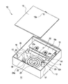
図1は本発明の第1実施形態にかかる照明器具を示す斜視図、図2(A)は本発明の実施形態にかかる平面らせん形蛍光ランプを器具本体側から見た斜視図、図2(B)は図2(A)中B方向から見た正面図である。
Hereinafter, embodiments of a flat spiral fluorescent lamp and a lighting apparatus according to the present invention will be described with reference to the drawings.
FIG. 1 is a perspective view showing a lighting fixture according to the first embodiment of the present invention, FIG. 2A is a perspective view of a flat spiral fluorescent lamp according to the embodiment of the present invention as seen from the fixture main body side, and FIG. FIG. 2B is a front view seen from the B direction in FIG.
図1に示すように、本発明にかかる照明器具10は、天井や壁等の壁面11に固定して使用するものであり、例えば矩形箱状の器具本体12と、器具本体12の前面開口を覆う透明あるいは半透明の樹脂等からなるパネル13を有している。器具本体12の底板12aには、一方の端部寄りに商用交流電源(図示省略)に接続されている点灯装置14等の電気部品が取付けられており、点灯装置14等を覆うとともにパネル13を取付けるための取付板15が設けられている。パネル13は、ネジ13aを取付板15のネジ穴15aに螺合し、締め付けることにより着脱可能に取付けられる。
As shown in FIG. 1, a
また、底板12の中央部および他方の端部寄りには、光源である平面らせん形蛍光ランプ20の照明光をパネル13側に反射して照明効率を向上させる反射板16が設けられており、反射板16の上面に、平面らせん形蛍光ランプ20を装着するための一対のランプソケット17、17が取付けられている。これらランプソケット17、17は、電源線(図示省略)によって、点灯装置14に接続されている。そして、器具本体12における平面らせん形蛍光ランプ20に対向する面である反射板16の上面には、平面らせん形蛍光ランプ20をランプソケット17に装着した際に、平面らせん形蛍光ランプ20の端部22bを保持するランプ支持バネ18が設けられている。
Further, a
図2(A)および(B)に示すように、平面らせん形蛍光ランプ20は、管状の放電路が長手方向中央部22aを始点として同一平面に沿って2重渦巻状に旋回された発光管22を有しており、発光管22の中央部22aは、その他の部分に比して太径となっていて、最冷点となっている。発光管22の両端部22bにはそれぞれ口金23、23が取付けられており、両口金23、23は、発光管22の中央部22aに対して、点対称の位置に設けられている。各口金23、23には、平面らせん形蛍光ランプ20の平面に直交する方向(図2(B)において上下方向)に配置された一対のランプピン21が、発光管22の軸方向に沿って突出して設けられている。
As shown in FIGS. 2 (A) and 2 (B), a flat spiral
発光管22における最冷点(22a)と反対側面(図2(B)において上側面)には、発光管22の両端部22b、22b同士を連結する保持部材であるブリッジ24が設けられており、ブリッジ24の両端には、発光管22を保持するためのリング状の保持部24aが設けられている。ブリッジ24の中央部には、最冷点である発光管22の中央部22aの近傍を通過しないように、発光管22の中央部(すなわち最冷点)22aを迂回する迂回部として開口25が設けられている。従って、発光管22の中央部22aとブリッジ24とは、接触しない。なお、開口25の形状としては、図2(A)に示すような円形や長円形とすることができるが、その他、矩形や、発光管22の中央部22aに対応した形状とすることもできる。
On the side opposite to the coldest spot (22a) of the arc tube 22 (upper side in FIG. 2B), a
以上、説明した本発明の第1実施形態にかかる照明器具10および平面らせん形蛍光ランプ20によれば、発光管22の両端部22b、22bを連結するブリッジ24に、最冷点部である管中央部22aを迂回する開口25を設けたので、発熱する発光管22の両端部22bを連結するブリッジ24と最冷点(22a)とは接触しない。このため、発光管22の端部22bの熱は、ブリッジ24を介して最冷点(22a)に伝達されないので、最冷点(22a)の温度上昇を抑えて、発光効率を改善することができる。
As described above, according to the
次に、本発明の第2実施形態にかかる平面らせん形蛍光ランプおよび照明器具について、図に基づいて説明する。
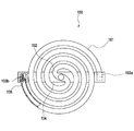
図3は本発明の第2実施形態にかかる平面らせん形蛍光灯を示す斜視図である。なお、前述した第1実施形態にかかる照明器具と共通する部位には同じ符号を付して、重複する説明を省略することとする。
Next, a flat spiral fluorescent lamp and a lighting fixture according to a second embodiment of the present invention will be described with reference to the drawings.
FIG. 3 is a perspective view showing a flat spiral fluorescent lamp according to a second embodiment of the present invention. In addition, suppose that the same code | symbol is attached | subjected to the site | part common to the lighting fixture concerning 1st Embodiment mentioned above, and the overlapping description is abbreviate | omitted.
図3に示すように、本発明の第2実施形態にかかる照明器具10Bに用いられる平面らせん形蛍光ランプ20Bでは、ブリッジ24の中央部が最冷点である発光管22の中央部22aの近傍を通過しないように、ブリッジ24の平面内において発光管22の中央部22aを迂回する迂回部として迂回路26が設けられている。迂回路26の形状は限定するものではないが、図3に示すように、部分円弧状に形成することができる。あるいは、矩形状(コ字状)に設けることもできる。
As shown in FIG. 3, in the flat spiral
以上、説明した本発明の第2実施形態にかかる照明器具10Bおよび平面らせん形蛍光ランプ20Bによれば、前述した第1実施形態にかかる照明器具10および平面らせん形蛍光ランプ20と同様の作用・効果を得ることができ、最冷点(22a)の温度上昇を抑えて、発光効率を改善することができる。
As described above, according to the illuminating
なお、本発明の平面らせん形蛍光ランプは、前述した各実施形態に限定されるものでなく、適宜な変形,改良等が可能である。 The flat spiral fluorescent lamp of the present invention is not limited to the above-described embodiments, and appropriate modifications and improvements can be made.
10 照明器具
20 平面らせん形蛍光ランプ
22 発光管
22a 管中央部
22b 端部
24 ブリッジ(保持部材)
25 開口(迂回部)
26 迂回路(迂回部)
DESCRIPTION OF
25 opening (bypass)
26 Detour (detour section)
Claims (3)
前記発光管の両端部を連結する保持部材が、最冷点部である前記管中央部を迂回する迂回部を有することを特徴とする平面らせん形蛍光ランプ。 A series of bent arc tubes is a flat spiral fluorescent lamp having a double spiral shape swirled in a spiral on a substantially single plane around the center of the tube,
A flat spiral fluorescent lamp characterized in that a holding member that connects both ends of the arc tube has a bypass portion that bypasses the tube central portion, which is the coldest spot portion.
Priority Applications (1)
| Application Number | Priority Date | Filing Date | Title |
|---|---|---|---|
| JP2008166440A JP5328237B2 (en) | 2008-06-25 | 2008-06-25 | Flat spiral fluorescent lamp and luminaire |
Applications Claiming Priority (1)
| Application Number | Priority Date | Filing Date | Title |
|---|---|---|---|
| JP2008166440A JP5328237B2 (en) | 2008-06-25 | 2008-06-25 | Flat spiral fluorescent lamp and luminaire |
Publications (2)
| Publication Number | Publication Date |
|---|---|
| JP2010009883A true JP2010009883A (en) | 2010-01-14 |
| JP5328237B2 JP5328237B2 (en) | 2013-10-30 |
Family
ID=41590128
Family Applications (1)
| Application Number | Title | Priority Date | Filing Date |
|---|---|---|---|
| JP2008166440A Expired - Fee Related JP5328237B2 (en) | 2008-06-25 | 2008-06-25 | Flat spiral fluorescent lamp and luminaire |
Country Status (1)
| Country | Link |
|---|---|
| JP (1) | JP5328237B2 (en) |
Citations (6)
| Publication number | Priority date | Publication date | Assignee | Title |
|---|---|---|---|---|
| JPH08236074A (en) * | 1994-12-28 | 1996-09-13 | Matsushita Electron Corp | Ring-shaped fluorescent lamp |
| JPH08236075A (en) * | 1994-12-28 | 1996-09-13 | Matsushita Electron Corp | Ring-shaped fluorescent lamp |
| JPH1064411A (en) * | 1996-08-23 | 1998-03-06 | Matsushita Electric Works Ltd | Base part for plate type fluorescent lamp |
| JP2007087968A (en) * | 2006-12-27 | 2007-04-05 | Matsushita Electric Ind Co Ltd | Arc tube, low-pressure mercury lamp and lighting system |
| JP2007273331A (en) * | 2006-03-31 | 2007-10-18 | Matsushita Electric Ind Co Ltd | Fluorescent lamp |
| JP2007273336A (en) * | 2006-03-31 | 2007-10-18 | Matsushita Electric Ind Co Ltd | Fluorescent lamp |
-
2008
- 2008-06-25 JP JP2008166440A patent/JP5328237B2/en not_active Expired - Fee Related
Patent Citations (6)
| Publication number | Priority date | Publication date | Assignee | Title |
|---|---|---|---|---|
| JPH08236074A (en) * | 1994-12-28 | 1996-09-13 | Matsushita Electron Corp | Ring-shaped fluorescent lamp |
| JPH08236075A (en) * | 1994-12-28 | 1996-09-13 | Matsushita Electron Corp | Ring-shaped fluorescent lamp |
| JPH1064411A (en) * | 1996-08-23 | 1998-03-06 | Matsushita Electric Works Ltd | Base part for plate type fluorescent lamp |
| JP2007273331A (en) * | 2006-03-31 | 2007-10-18 | Matsushita Electric Ind Co Ltd | Fluorescent lamp |
| JP2007273336A (en) * | 2006-03-31 | 2007-10-18 | Matsushita Electric Ind Co Ltd | Fluorescent lamp |
| JP2007087968A (en) * | 2006-12-27 | 2007-04-05 | Matsushita Electric Ind Co Ltd | Arc tube, low-pressure mercury lamp and lighting system |
Also Published As
| Publication number | Publication date |
|---|---|
| JP5328237B2 (en) | 2013-10-30 |
Similar Documents
| Publication | Publication Date | Title |
|---|---|---|
| JP3139714U (en) | LED lamp | |
| JP2010171236A (en) | Led lamp | |
| JP5328237B2 (en) | Flat spiral fluorescent lamp and luminaire | |
| JP4433975B2 (en) | lighting equipment | |
| JP5328238B2 (en) | Flat spiral fluorescent lamp and luminaire | |
| JP2009176501A (en) | Lighting fixture | |
| JP2006202668A (en) | Fluorescent lamp, fluorescent lamp device and luminaire | |
| JP4966842B2 (en) | Lighting device | |
| JP2010009880A (en) | Lighting apparatus | |
| JP2007042290A (en) | Fluorescent lamp device and luminaire | |
| JP2010251261A (en) | Lighting device | |
| JP5127044B2 (en) | lighting equipment | |
| JP3206766U (en) | Electrodeless lighting device | |
| JP2006012542A (en) | Fluorescent lamp and illumination apparatus | |
| JP6043587B2 (en) | LED lighting device | |
| JP2009176656A (en) | Lighting apparatus | |
| JP2009289440A (en) | Luminaire | |
| JP2011090928A (en) | Lighting fixture | |
| JP5172626B2 (en) | lighting equipment | |
| JP2011096384A (en) | Lighting fixture | |
| JP2010073511A (en) | Fixture for fluorescent lamp | |
| JP2009176500A (en) | Lighting fixture | |
| JP2006286422A (en) | Fluorescent lamp device and lighting system | |
| JP2011090994A (en) | Lighting fixture | |
| JP2006286378A (en) | Fluorescent lamp apparatus and lighting device |
Legal Events
| Date | Code | Title | Description |
|---|---|---|---|
| A621 | Written request for application examination |
Free format text: JAPANESE INTERMEDIATE CODE: A621 Effective date: 20110617 |
|
| A711 | Notification of change in applicant |
Free format text: JAPANESE INTERMEDIATE CODE: A712 Effective date: 20120111 |
|
| A977 | Report on retrieval |
Free format text: JAPANESE INTERMEDIATE CODE: A971007 Effective date: 20120119 |
|
| A131 | Notification of reasons for refusal |
Free format text: JAPANESE INTERMEDIATE CODE: A131 Effective date: 20120508 |
|
| A521 | Written amendment |
Free format text: JAPANESE INTERMEDIATE CODE: A523 Effective date: 20120702 |
|
| A131 | Notification of reasons for refusal |
Free format text: JAPANESE INTERMEDIATE CODE: A131 Effective date: 20121225 |
|
| A521 | Written amendment |
Free format text: JAPANESE INTERMEDIATE CODE: A523 Effective date: 20130208 |
|
| TRDD | Decision of grant or rejection written | ||
| A01 | Written decision to grant a patent or to grant a registration (utility model) |
Free format text: JAPANESE INTERMEDIATE CODE: A01 Effective date: 20130625 |
|
| A61 | First payment of annual fees (during grant procedure) |
Free format text: JAPANESE INTERMEDIATE CODE: A61 Effective date: 20130723 |
|
| R150 | Certificate of patent or registration of utility model |
Free format text: JAPANESE INTERMEDIATE CODE: R150 |
|
| LAPS | Cancellation because of no payment of annual fees |