JP2010008309A - Partial discharge measurement device - Google Patents
Partial discharge measurement device Download PDFInfo
- Publication number
- JP2010008309A JP2010008309A JP2008169951A JP2008169951A JP2010008309A JP 2010008309 A JP2010008309 A JP 2010008309A JP 2008169951 A JP2008169951 A JP 2008169951A JP 2008169951 A JP2008169951 A JP 2008169951A JP 2010008309 A JP2010008309 A JP 2010008309A
- Authority
- JP
- Japan
- Prior art keywords
- partial discharge
- resonance
- coil
- measurement
- circuit
- Prior art date
- Legal status (The legal status is an assumption and is not a legal conclusion. Google has not performed a legal analysis and makes no representation as to the accuracy of the status listed.)
- Pending
Links
Images


Landscapes
- Testing Relating To Insulation (AREA)
Abstract
Description
本発明は、高電圧機器内部で発生した部分放電信号を、当該高電圧機器と接続されている接地線を介して検出及び測定する部分放電測定装置に関する。 The present invention relates to a partial discharge measuring apparatus that detects and measures a partial discharge signal generated inside a high voltage device via a ground line connected to the high voltage device.
電力設備の高経年化に伴い、機器の寿命評価あるいは延命化を判断できる絶縁診断技術の向上に大きな関心が寄せられている。絶縁診断の方法としては電気的、化学的、光学的手法など様々に試みが行われ、また、実績を重ねている。こうした中で、接地線を用いた部分放電測定は活線状態で測定が可能であり、かつ、機器への侵襲が少ないため現地測定には簡便であり広く使われている。一方、機器内部で発生した部分放電信号の一部しか接地線に流れないことから検出感度が低いという問題があった。そこで、特許文献1では、複数の特定周波数成分のそれぞれに共振する共振回路を備えることにより、検出感度の向上を図る測定装置が記載されている。 Along with the aging of electric power facilities, there is a great interest in improving insulation diagnosis technology that can judge the life evaluation or prolongation of life of equipment. Various methods such as electrical, chemical, and optical methods have been tried as insulation diagnosis methods, and the results have been accumulated. Under these circumstances, partial discharge measurement using a grounding wire can be performed in a live line state, and since it is less invasive to equipment, it is simple and widely used for on-site measurement. On the other hand, since only a part of the partial discharge signal generated inside the device flows to the ground line, there is a problem that the detection sensitivity is low. Therefore, Patent Document 1 describes a measuring device that improves detection sensitivity by providing a resonance circuit that resonates with each of a plurality of specific frequency components.
ところで、現地測定においては、広範な周波数帯域にて存在する部分放電信号の測定を、多くの外来ノイズが混在する環境下で行わざるを得ず、特許文献1のように特定された共振周波数では十分な検出感度を得ることが困難である。そこで、特許文献2では、コイルの内側に挿入された鉄心によりインダクタンスを変化させる可変インダクタを備えた共振回路により共振周波数を調整可能とし測定環境に適応させることができる測定装置が記載されている。
しかし、特許文献2に示した測定装置では、そもそも微弱な部分放電信号が、鉄心を備えた可変インダクタにより信号の損失が生じてしまい、外来ノイズが混在する測定環境下で高感度を維持した部分放電測定が難しいという問題があった。 However, in the measurement apparatus shown in Patent Document 2, a weak partial discharge signal is a signal loss caused by a variable inductor having an iron core, and high sensitivity is maintained in a measurement environment in which external noise is mixed. There was a problem that discharge measurement was difficult.
そこで、本件発明では、上記課題を解決するために、第一の発明として、高電圧機器にて発生する部分放電を測定するための装置であって、部分放電によって生じるパルス信号によって起電力を発生する1次コイルと、1次コイルからの電磁界を受けるインダクタンスが固定の2次コイルと、前記2次コイルと並列に配置され、1次コイルからの電磁界によって2次コイルとともに共振回路を構成可能に容量を調整できる第一可変コンデンサと、を備えた部分放電測定装置を提供する。この場合、磁性材による信号損失を回避するために、前記インダクタンスが固定の2次コイルは空心であることが好ましい。 Therefore, in the present invention, in order to solve the above problems, as a first invention, an apparatus for measuring a partial discharge generated in a high-voltage device, wherein an electromotive force is generated by a pulse signal generated by the partial discharge. A primary coil that receives the electromagnetic field from the primary coil, a fixed secondary coil that receives the electromagnetic field from the primary coil, and a secondary coil that is arranged in parallel with the secondary coil to form a resonance circuit together with the secondary coil by the electromagnetic field from the primary coil A partial discharge measuring device including a first variable capacitor whose capacity can be adjusted as much as possible is provided. In this case, in order to avoid signal loss due to the magnetic material, the secondary coil having a fixed inductance is preferably air-core.
第二の発明としては、第二可変コンデンサと、前記第二可変コンデンサを第一可変コンデンサに並列に接続するための第一スイッチと、をさらに有する第一の発明に記載した部分放電測定装置を提供する。 As a second invention, there is provided the partial discharge measuring device according to the first invention, further comprising a second variable capacitor and a first switch for connecting the second variable capacitor to the first variable capacitor in parallel. provide.
第三の発明としては、第二スイッチを介して前記共振回路と接続可能となる回路であって、前記共振回路の共振パルス信号を増幅する増幅回路をさらに有する第一または第二に記載した部分放電測定装置を提供する。 A third aspect of the invention is a circuit that can be connected to the resonance circuit via a second switch, and further includes an amplification circuit that amplifies a resonance pulse signal of the resonance circuit. A discharge measuring device is provided.
第四の発明としては、前記増幅回路は、前記共振回路に第二スイッチを介して直列接続されるインダクタンスを可変とするピーキングコイルである第三の発明に記載した部分放電測定装置を提供する。 As a fourth invention, there is provided the partial discharge measuring device according to the third invention, wherein the amplifier circuit is a peaking coil having a variable inductance connected in series to the resonance circuit via a second switch.
第五の発明としては、前記1次コイルは、分断された接地線間に直接取り付けられる第一ないし第四の発明に記載した部分放電測定装置を提供する。 As a fifth aspect of the invention, there is provided the partial discharge measuring device according to any one of the first to fourth aspects, wherein the primary coil is directly attached between the divided ground wires.
本件発明により、現地測定において、より高い検出感度で測定可能な部分放電測定装置を提供する。 According to the present invention, there is provided a partial discharge measuring device capable of measuring with higher detection sensitivity in on-site measurement.
以下に本発明を実施するための最良の形態を説明する。なお本発明はこれらの実施形態に何ら限定されるものではなく、その要旨を逸脱しない範囲において、種々なる態様で実施し得る。 The best mode for carrying out the present invention will be described below. The present invention is not limited to these embodiments, and can be implemented in various modes without departing from the scope of the invention.
実施形態1は主に請求項1について説明する。実施形態2は主に請求項2について説明する。実施形態3は主に請求項3について説明する。実施形態4は主に請求項4について説明する。実施形態5は主に請求項5について説明する。
<実施形態1>
<実施形態1 概要>
The first embodiment will mainly describe claim 1. The second embodiment will mainly describe claim 2. The third embodiment will mainly describe claim 3. The fourth embodiment will mainly describe claim 4. The fifth embodiment will mainly describe claim 5.
<Embodiment 1>
<Overview of Embodiment 1>
本実施形態は、部分放電によって生じるパルス信号によって起電力を発生する1次コイルと、1次コイルからの電磁界を受けるインダクタンスが固定の2次コイルと、前記2次コイルと並列に配置され、1次コイルからの電磁界によって2次コイルとともに共振回路を構成可能に容量を調整できる第一可変コンデンサとを備えたことを特徴とする部分放電測定装置である。 In this embodiment, a primary coil that generates an electromotive force by a pulse signal generated by partial discharge, a secondary coil that receives an electromagnetic field from the primary coil is fixed, and the secondary coil is arranged in parallel. A partial discharge measuring apparatus comprising: a first variable capacitor capable of adjusting a capacity so that a resonance circuit can be configured together with a secondary coil by an electromagnetic field from a primary coil.
電力用変圧器などの高電圧機器には、感電事故防止や故障時の大電流による機器損傷防止のため接地がなされている。接地線には高電圧機器内部で生じた部分放電パルス信号が流れる。このパルス信号を、インダクタンスが固定のコイルと可変コンデンサとで構成される並列共振回路により共振周波数を変化させ現地において最も感度の良い共振周波数を選択する。
<実施形態1 構成>
High-voltage devices such as power transformers are grounded to prevent electric shock accidents and damage to devices due to large currents at the time of failure. A partial discharge pulse signal generated inside the high-voltage device flows through the ground line. The resonance frequency of this pulse signal is changed by a parallel resonance circuit composed of a coil having a fixed inductance and a variable capacitor, and the resonance frequency with the highest sensitivity is selected in the field.
<Configuration of Embodiment 1>
本実施形態の部分放電測定装置は、部分放電によって生じるパルス信号によって起電力を発生する1次コイルと、1次コイルからの電磁界を受けるインダクタンスが固定の2次コイルと、前記2次コイルと並列に配置され、1次コイルからの電磁界によって2次コイルとともに共振回路を構成可能に容量を調整できる第一可変コンデンサとを有する。本実施形態における回路構成の概略を図1に示す。 The partial discharge measuring apparatus according to the present embodiment includes a primary coil that generates an electromotive force by a pulse signal generated by partial discharge, a secondary coil having a fixed inductance that receives an electromagnetic field from the primary coil, and the secondary coil. A first variable capacitor which is arranged in parallel and whose capacity can be adjusted so that a resonance circuit can be configured with the secondary coil by an electromagnetic field from the primary coil. An outline of the circuit configuration in this embodiment is shown in FIG.
「1次コイル」(0101)には、接地線(0102)から検出された部分放電によって生じたパルス信号が入力される。パルス信号の検出には、例えば、接地線等に取り付けたクランプ式の高周波変流器(CT)や、あるいは、接地線の近傍に取り付けた単巻ループアンテナを用いる。この単巻ループアンテナは、電線をリング状に複数回巻いたコイルであり、部分放電による電磁波を検出することができる。 A pulse signal generated by partial discharge detected from the ground line (0102) is input to the “primary coil” (0101). For detection of the pulse signal, for example, a clamp-type high-frequency current transformer (CT) attached to a ground wire or the like, or a single loop antenna attached in the vicinity of the ground wire is used. This single loop antenna is a coil in which an electric wire is wound a plurality of times in a ring shape, and can detect electromagnetic waves caused by partial discharge.
「2次コイル」(0103)は、前記1次コイルと相互インダクタンスにより結合されている。部分放電信号は高周波成分を含むので、相互インダクタンスには、鉄損の少ない材料の鉄心を使用した物や、あるいは、空心の物が好ましい。この2次コイルと並列に接続された第一可変コンデンサ(0104)とともに並列共振回路を構成し、1次コイルに入力されたパルス信号を共振周波数において増幅する。この2次コイルはインダクタンスが固定の空心コイルを使用する。これにより磁性材料を鉄心とすることに起因するパルス信号の損失は生じない。 The “secondary coil” (0103) is coupled to the primary coil by mutual inductance. Since the partial discharge signal includes a high frequency component, the mutual inductance is preferably a material using an iron core made of a material having a small iron loss or an air core. A parallel resonant circuit is configured with the first variable capacitor (0104) connected in parallel with the secondary coil, and the pulse signal input to the primary coil is amplified at the resonance frequency. The secondary coil uses an air-core coil with a fixed inductance. As a result, there is no loss of pulse signal due to the magnetic material being an iron core.
「第一可変コンデンサ」は、容量可変型コンデンサを用い前記2次コイルとともに並列共振回路を構成する。この第一可変コンデンサには、例えば、通信機の同調回路に用いられている、いわゆるバリコン等を使用することができる。容量の範囲は一般的には1pF〜100pF程度が多い。第一可変コンデンサの容量を調節して、現地測定の環境に応じて最も感度の良い共振周波数を選択することにより、簡易に検出感度を向上させることができる。 The “first variable capacitor” uses a variable capacitance capacitor and forms a parallel resonant circuit together with the secondary coil. As the first variable capacitor, for example, a so-called variable capacitor used in a tuning circuit of a communication device can be used. The range of capacitance is generally about 1 pF to 100 pF. By adjusting the capacitance of the first variable capacitor and selecting the resonance frequency with the highest sensitivity according to the field measurement environment, the detection sensitivity can be easily improved.
具体的な測定においては、コンデンサ(0105)の両端の電圧が測定値となる。本実施例の部分放電測定装置は、種々の測定環境下で良好な測定感度を得られることから、ポータブルで汎用性の高い測定機器として利用することができる。以下の実施例2ないし実施例5についても同様である。 In a specific measurement, the voltage across the capacitor (0105) becomes the measured value. Since the partial discharge measuring apparatus of this embodiment can obtain good measurement sensitivity under various measurement environments, it can be used as a portable and highly versatile measuring instrument. The same applies to Examples 2 to 5 below.
本実施例の回路構成を用いた部分放電測定器を試作して実験を行った。接地線を模したリード線に高周波変流器(周波数特性:2kHz−30MHz)を取り付け、この出力を1次コイルに接続した。一次側電圧をV1、二次側電圧をV2とし、両者の比をQ値として測定した。信号源にはパルス発生器を用いた。回路定数を一定とし、周波数fを変えてQ値を測定した。結果は、20kHzから180kHzの範囲でQ値が10以上となった。すなわち、部分放電パルス電流に含まれる周波数がこの中にあれば、測定中に共振周波数を変化させることにより、検出感度を向上させることができる。また、周波数が1kHz以下や1MHz以上の時のQ値は、1以下となった。つまり、1kHz以下や1MHz以上の周波数で発生している外部ノイズ等を除去できる。
<実施形態1 効果>
A partial discharge measuring device using the circuit configuration of this example was experimentally manufactured and tested. A high-frequency current transformer (frequency characteristic: 2 kHz-30 MHz) was attached to the lead wire imitating the ground wire, and this output was connected to the primary coil. The primary voltage V 1, and the secondary-side voltage V 2, to measure the ratio of the two as the Q value. A pulse generator was used as the signal source. The Q value was measured by changing the frequency f while keeping the circuit constant constant. As a result, Q value became 10 or more in the range of 20kHz to 180kHz. That is, if the frequency included in the partial discharge pulse current is within this range, the detection sensitivity can be improved by changing the resonance frequency during measurement. The Q value was 1 or less when the frequency was 1 kHz or less or 1 MHz or more. That is, external noise generated at frequencies of 1 kHz or less or 1 MHz or more can be removed.
<Embodiment 1 effect>
本実施形態の部分放電測定装置により、周囲の電気的雑音の影響を受けやすい現地測定において、共振周波数を可変とすることで電気的雑音の少ない周波数を選択することにより、SN比を向上させ高感度な部分放電測定が簡易に可能となる。
<実施形態2>
<実施形態2 概要>
With the partial discharge measurement device of the present embodiment, in the field measurement that is easily affected by the surrounding electrical noise, by selecting a frequency with less electrical noise by making the resonance frequency variable, the SN ratio is improved. Sensitive partial discharge measurement can be easily performed.
<Embodiment 2>
<Overview of Embodiment 2>
本実施形態は、第二可変コンデンサと、前記第二可変コンデンサを第一可変コンデンサに並列に接続するための第一スイッチと、をさらに有することを特徴とする部分放電測定装置である。
<実施形態2 構成>
The present embodiment is a partial discharge measuring apparatus further comprising a second variable capacitor and a first switch for connecting the second variable capacitor to the first variable capacitor in parallel.
<Configuration of Embodiment 2>
本実施形態の部分放電測定装置は、実施形態1の部分放電測定装置にさらに、第二可変コンデンサと、前記第二可変コンデンサを第一可変コンデンサに並列に接続するための第一スイッチを有する。本実施形態の回路構成の概略を図2に示す。 The partial discharge measuring apparatus according to the present embodiment further includes a second variable capacitor and a first switch for connecting the second variable capacitor to the first variable capacitor in parallel to the partial discharge measuring apparatus according to the first embodiment. An outline of the circuit configuration of this embodiment is shown in FIG.
「第二可変コンデンサ」(0201)は、第一スイッチにより第一可変コンデンサと並列に接続可能となり、第一可変コンデンサ(0203)と同様に容量を変化せることができる。部分放電パルス信号は幅広い周波数スペクトルにわたって発生するところ、二つのコンデンサを接続することにより静電容量の可変範囲を広くすることができ、現地測定においてより柔軟に対応することが可能となる。また、第三あるいは第四可変コンデンサ等をスイッチと共にさらに並列接続することにより、静電容量の可変範囲を広くして共振を得られる範囲を拡張することもできる。また、第三あるいは第四可変コンデンサ等を、第一あるいは第二可変コンデンサにスイッチと共に直列に接続することにより合成静電容量を小さくすることにより静電容量の可変範囲を広げることもできる。 The “second variable capacitor” (0201) can be connected in parallel with the first variable capacitor by the first switch, and the capacitance can be changed in the same manner as the first variable capacitor (0203). The partial discharge pulse signal is generated over a wide frequency spectrum. By connecting two capacitors, it is possible to widen the variable range of the capacitance, and it is possible to respond more flexibly in the field measurement. Further, by further connecting a third or fourth variable capacitor or the like together with the switch, it is possible to expand the range in which resonance can be obtained by widening the variable range of capacitance. Further, by connecting the third or fourth variable capacitor or the like in series with the first or second variable capacitor together with the switch, the variable capacitance range can be expanded by reducing the combined capacitance.
「第一スイッチ」(0202)は、第一可変コンデンサの調整では、測定中の周波数と十分な共振が得られない場合であっても、第一スイッチを第二可変コンデンサに接続することにより、静電容量の可変範囲を広くして共振を得ることができる。
<実施形態2 効果>
The “first switch” (0202) is configured by connecting the first switch to the second variable capacitor even when the adjustment of the first variable capacitor does not provide sufficient resonance with the frequency being measured. Resonance can be obtained by widening the variable range of the capacitance.
<Embodiment 2 Effect>
本実施形態の部分放電測定装置により、広範な周波数帯域にわたり生じている部分放電パルス信号を、測定環境に応じて高感度で測定することが可能となる。
<実施形態3>
<実施形態3 概要>
With the partial discharge measurement device of this embodiment, it is possible to measure a partial discharge pulse signal generated over a wide frequency band with high sensitivity according to the measurement environment.
<Embodiment 3>
<Overview of Embodiment 3>
本実施形態は、第二スイッチを介して前記共振回路と接続可能となる回路であって、前記共振回路の共振パルス信号を増幅する増幅回路をさらに有することを特徴とする部分放電測定装置である。前記共振回路において所望の共振周波数にて検出された部分放電パルス信号は、第二スイッチを介して接続された増幅回路により所望の出力にて増幅される。
<実施形態3 構成>
This embodiment is a partial discharge measuring apparatus that is a circuit that can be connected to the resonance circuit via a second switch, and further includes an amplification circuit that amplifies the resonance pulse signal of the resonance circuit. . A partial discharge pulse signal detected at a desired resonance frequency in the resonance circuit is amplified at a desired output by an amplifier circuit connected via a second switch.
<Configuration of Embodiment 3>
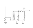
本実施形態の部分放電測定装置は、実施形態1または実施形態2の部分放電測定装置にさらに、第二スイッチ(0301)を介して前記共振回路と接続可能となる回路であって、前記共振回路のパルス信号を増幅する増幅回路を有する。本実施形態の回路構成の概略を図3に示す。 The partial discharge measuring apparatus of the present embodiment is a circuit that can be connected to the resonant circuit via a second switch (0301) in addition to the partial discharge measuring apparatus of the first or second embodiment, and the resonant circuit An amplifying circuit for amplifying the pulse signal. An outline of the circuit configuration of this embodiment is shown in FIG.
「増幅回路」(0302)は、第二スイッチを介して前記共振回路に接続されている。共振パルス信号は、この増幅回路を経て所望の出力に増幅され、所定の機器、例えばオシロスコープやコンピュータ等へ伝送され、表示や記録等の処理に供される。
本実施例の増幅回路では、FET(電界効果トランジスタ)(0303)を用いている。可変抵抗(0304)は、動作点を定めるバイアスであり、これと並列に接続されているのは接地側への高周波バイパス用のコンデンサ(0305)である。コイル(0306)は高周波信号が電源(0307)へ流入することをブロックしている。増幅された高周波信号はハイパスフィルタとなるコンデンサ(0308)を経て所定の測定器等に出力される。なお、増幅回路は概略図においてはFETを用いたものとしているが、これに限定されるものではなく入力信号を所望のレベルに増幅するものであればよい。
<実施形態3 効果>
An “amplifier circuit” (0302) is connected to the resonant circuit via a second switch. The resonance pulse signal is amplified to a desired output through this amplification circuit, transmitted to a predetermined device such as an oscilloscope or a computer, and used for processing such as display and recording.
In the amplifier circuit of this embodiment, an FET (Field Effect Transistor) (0303) is used. The variable resistor (0304) is a bias that determines an operating point, and a capacitor (0305) for high-frequency bypass to the ground side is connected in parallel with the variable resistor (0304). The coil (0306) blocks the high frequency signal from flowing into the power source (0307). The amplified high frequency signal is output to a predetermined measuring instrument or the like through a capacitor (0308) serving as a high pass filter. In the schematic diagram, the amplifying circuit uses an FET, but the present invention is not limited to this, and any amplifier that amplifies an input signal to a desired level may be used.
<Effect of Embodiment 3>
増幅回路を備えた本実施形態の部分放電測定装置により、検出された部分放電パルス信号を所望の機器の入力インピーダンスに応じて出力することができる。
<実施形態4>
<実施形態4 概要>
With the partial discharge measuring apparatus of this embodiment provided with an amplifier circuit, the detected partial discharge pulse signal can be output according to the input impedance of a desired device.
<Embodiment 4>
<Outline of Embodiment 4>
本実施形態は、前記増幅回路が、前記共振回路に第二スイッチを介して直列接続されるインダクタンスを可変とするピーキングコイルであることを特徴とする部分放電測定装置である。このピーキングコイルが前記共振回路と接続されることにより、さらに直列共振回路を構成する。
<実施形態4 構成>
In this embodiment, the amplifier circuit is a peaking coil having a variable inductance connected in series to the resonance circuit via a second switch. The peaking coil is connected to the resonance circuit to further constitute a series resonance circuit.
<Configuration of Embodiment 4>
本実施形態の部分放電測定装置は、実施形態3における増幅回路が、前記共振回路に第二スイッチを介して直列接続されるインダクタンスを可変とするピーキングコイルとなるものである。本実施形態の回路構成の概略を図4に示す。 In the partial discharge measuring apparatus according to the present embodiment, the amplifier circuit according to the third embodiment is a peaking coil in which the inductance connected in series to the resonance circuit via a second switch is variable. An outline of the circuit configuration of this embodiment is shown in FIG.
「ピーキングコイル」(0401)は、空心コイルであってインダクタンスが可変のものである。このピーキングコイルは前記並列共振回路と直列に接続されることにより、さらに直列共振回路を構成する。 The “peaking coil” (0401) is an air-core coil whose inductance is variable. This peaking coil is further connected in series with the parallel resonant circuit to further constitute a series resonant circuit.
前記並列共振回路と増幅器等を接続すると、その影響により共振条件が崩れてしまう場合が生じる。そこで、ピーキングコイルを接続することにより、前記並列共振回路で得られた共振条件に影響を及ぼすことなく、さらに直列共振回路を構成することができる。この場合、前記並列共振回路で共振を得られることに加え、前記並列共振回路とピーキングコイルとの直列共振回路により、さらに共振を得ることができる。したがって、共振が得られる周波数範囲を広げることができ、広範な周波数帯域に対して高い測定感度を維持することができる。また、ピーキングコイルは、増幅回路の高周波特性の改善に役立つ。 When the parallel resonant circuit is connected to an amplifier or the like, the resonance condition may collapse due to the influence. Therefore, by connecting a peaking coil, a series resonance circuit can be further configured without affecting the resonance conditions obtained by the parallel resonance circuit. In this case, in addition to obtaining resonance by the parallel resonance circuit, further resonance can be obtained by the series resonance circuit of the parallel resonance circuit and the peaking coil. Therefore, the frequency range in which resonance can be obtained can be expanded, and high measurement sensitivity can be maintained over a wide frequency band. The peaking coil is useful for improving the high frequency characteristics of the amplifier circuit.
測定においては、前記並列共振回路において第一並びに第二コンデンサを調整し共振条件を満たした上で、ピーキングコイルを接続し直列共振条件となるように可変インダクタンスを調整することが望ましい。また、測定環境によっては、部分放電信号の周波数成分が並列共振回路の共振条件と整合しない場合であっても、ピーキングコイルのインダクタンスの調整により共振条件とすることができる。
<実施形態4 効果>
In the measurement, it is desirable to adjust the first and second capacitors in the parallel resonance circuit to satisfy the resonance condition, and then connect the peaking coil to adjust the variable inductance so as to satisfy the series resonance condition. Depending on the measurement environment, even if the frequency component of the partial discharge signal does not match the resonance condition of the parallel resonance circuit, the resonance condition can be set by adjusting the inductance of the peaking coil.
<Embodiment 4 effect>
本実施形態の部分放電測定装置により、様々な現地測定環境下において、より広い周波数帯域に対し高感度、高SN比を有する部分放電測定が可能となる。
<実施形態5>
<実施形態5 概要>
The partial discharge measuring apparatus according to the present embodiment enables partial discharge measurement having high sensitivity and high SN ratio over a wider frequency band under various on-site measurement environments.
<Embodiment 5>
<Overview of Embodiment 5>
本実施形態は、前記1次コイルが、分断された接地線間に直接取り付けられることを特徴とする部分放電測定装置である。
<実施形態5 構成>
This embodiment is the partial discharge measuring apparatus, wherein the primary coil is directly attached between the divided ground wires.
<Embodiment 5 configuration>
本実施形態の部分放電測定装置は、実施形態1ないし実施形態4における1次コイルが、分断された接地線間に直接取り付けられるものである。 In the partial discharge measuring apparatus of this embodiment, the primary coil in Embodiments 1 to 4 is directly attached between the divided ground wires.
高電圧機器の接地線が取り外し可能な場合には、上記クランプ式の高周波変流器等を介することは不要となり、上記1次コイルを分断された接地線間に挿入して取り付けることにより部分放電信号を検出する。この場合は、高周波変流器を介することによる部分放電信号の損失がなく、その分測定感度が向上する。
<実施形態5 効果>
When the ground wire of high-voltage equipment can be removed, it is not necessary to go through the clamp-type high-frequency current transformer, etc., and partial discharge can be achieved by inserting the primary coil between the separated ground wires. Detect the signal. In this case, there is no loss of the partial discharge signal due to passing through the high-frequency current transformer, and the measurement sensitivity is improved accordingly.
<Effect of Embodiment 5>
本実施形態の部分放電測定装置により、微小な電気信号である部分放電信号を高感度で測定することができる。 With the partial discharge measuring apparatus of this embodiment, a partial discharge signal that is a minute electric signal can be measured with high sensitivity.
0101 1次コイル
0102 接地線
0103 2次コイル
0104 第一可変コンデンサ
0105 コンデンサ
0101
Claims (5)
部分放電によって生じるパルス信号によって起電力を発生する1次コイルと、
1次コイルからの電磁界を受けるインダクタンスが固定の2次コイルと、
前記2次コイルと並列に配置され、1次コイルからの電磁界によって2次コイルとともに共振回路を構成可能に容量を調整できる第一可変コンデンサと、
を備えた部分放電測定装置。 An apparatus for measuring a partial discharge generated in a high voltage device,
A primary coil that generates an electromotive force by a pulse signal generated by partial discharge;
A secondary coil having a fixed inductance that receives an electromagnetic field from the primary coil;
A first variable capacitor arranged in parallel with the secondary coil and capable of adjusting a capacity so that a resonance circuit can be configured with the secondary coil by an electromagnetic field from the primary coil;
A partial discharge measuring device.
前記第二可変コンデンサを第一可変コンデンサに並列に接続するための第一スイッチと、
をさらに有する請求項1に記載の部分放電測定装置。 A second variable capacitor;
A first switch for connecting the second variable capacitor to the first variable capacitor in parallel;
The partial discharge measuring device according to claim 1, further comprising:
Priority Applications (1)
| Application Number | Priority Date | Filing Date | Title |
|---|---|---|---|
| JP2008169951A JP2010008309A (en) | 2008-06-30 | 2008-06-30 | Partial discharge measurement device |
Applications Claiming Priority (1)
| Application Number | Priority Date | Filing Date | Title |
|---|---|---|---|
| JP2008169951A JP2010008309A (en) | 2008-06-30 | 2008-06-30 | Partial discharge measurement device |
Publications (1)
| Publication Number | Publication Date |
|---|---|
| JP2010008309A true JP2010008309A (en) | 2010-01-14 |
Family
ID=41588988
Family Applications (1)
| Application Number | Title | Priority Date | Filing Date |
|---|---|---|---|
| JP2008169951A Pending JP2010008309A (en) | 2008-06-30 | 2008-06-30 | Partial discharge measurement device |
Country Status (1)
| Country | Link |
|---|---|
| JP (1) | JP2010008309A (en) |
Cited By (6)
| Publication number | Priority date | Publication date | Assignee | Title |
|---|---|---|---|---|
| CN104820176A (en) * | 2015-05-27 | 2015-08-05 | 中国人民解放军军械工程学院 | Double-coupling Duffing oscillator adaptive detecting method for weak transient electromagnetic radiation signals |
| JPWO2015049725A1 (en) * | 2013-10-01 | 2017-03-09 | 三菱電機株式会社 | Partial discharge sensor |
| CN108508338A (en) * | 2018-03-01 | 2018-09-07 | 武汉拓普联合电力设备有限公司 | Frequency conversion resonance experiment device |
| JP2020101490A (en) * | 2018-12-25 | 2020-07-02 | 株式会社明電舎 | Partial discharge detector and partial discharge detection method |
| CN111458616A (en) * | 2020-05-15 | 2020-07-28 | 广东电科院能源技术有限责任公司 | Device and method for improving signal-to-noise ratio of common-mode interference suppression partial discharge |
| JP2021015046A (en) * | 2019-07-12 | 2021-02-12 | 日東工業株式会社 | Portable type discharge detector |
-
2008
- 2008-06-30 JP JP2008169951A patent/JP2010008309A/en active Pending
Cited By (7)
| Publication number | Priority date | Publication date | Assignee | Title |
|---|---|---|---|---|
| JPWO2015049725A1 (en) * | 2013-10-01 | 2017-03-09 | 三菱電機株式会社 | Partial discharge sensor |
| CN104820176A (en) * | 2015-05-27 | 2015-08-05 | 中国人民解放军军械工程学院 | Double-coupling Duffing oscillator adaptive detecting method for weak transient electromagnetic radiation signals |
| CN108508338A (en) * | 2018-03-01 | 2018-09-07 | 武汉拓普联合电力设备有限公司 | Frequency conversion resonance experiment device |
| JP2020101490A (en) * | 2018-12-25 | 2020-07-02 | 株式会社明電舎 | Partial discharge detector and partial discharge detection method |
| JP7373276B2 (en) | 2018-12-25 | 2023-11-02 | 株式会社明電舎 | Partial discharge detection device and partial discharge detection method |
| JP2021015046A (en) * | 2019-07-12 | 2021-02-12 | 日東工業株式会社 | Portable type discharge detector |
| CN111458616A (en) * | 2020-05-15 | 2020-07-28 | 广东电科院能源技术有限责任公司 | Device and method for improving signal-to-noise ratio of common-mode interference suppression partial discharge |
Similar Documents
| Publication | Publication Date | Title |
|---|---|---|
| JP2010008309A (en) | Partial discharge measurement device | |
| JP4840050B2 (en) | Partial discharge measuring device | |
| US8581579B2 (en) | Magneto electric sensor with injected up-conversion or down-conversion | |
| US10502778B2 (en) | Method and apparatus for electric arc detection | |
| US11050401B2 (en) | Current sensor and measurement device | |
| JP6305184B2 (en) | Current sensor and measuring device | |
| JPWO2016136567A1 (en) | Voltage detection circuit, power transmission device and power transmission system | |
| CN104515931B (en) | A kind of DC leakage flow sensor based on magnetic modulation | |
| JPH07115339A (en) | Line filter and its impedance changing method | |
| US10209296B2 (en) | Circuit and method for testing RF device and RF device with built-in testing circuit | |
| JP2016194483A (en) | Current detection device | |
| CN110571127A (en) | Radio frequency power supply for multipole ion trap and ion guide device | |
| Van den Bossche et al. | EMC combined di/dt current probe | |
| JP2011038964A (en) | Current sensor | |
| CN218180953U (en) | Low-current signal measuring device under direct-current coupling condition | |
| CN111398727B (en) | Noise filtering equipment and electromagnetic compatibility test system | |
| JP2022185736A (en) | partial discharge detector | |
| Li et al. | Broadband matching of nuclear quadrupole resonance detector using non-Foster circuits | |
| JPH02287169A (en) | Detection of corona discharge | |
| JP2000314756A (en) | Noise testing device and method | |
| WO2009017275A1 (en) | Self-examination type cast resin transformer | |
| JP2004257770A (en) | High-frequency electric potential detection device | |
| KR101663816B1 (en) | Current transformer for wide bandwidth range | |
| SU1188681A1 (en) | Apparatus for measuring strength of weak variable magnetic fields | |
| JP2020183878A (en) | High-speed and high-sensitivity magnetic sensor |