JP2010008143A - Optical path monitoring apparatus and optical path monitoring system - Google Patents
Optical path monitoring apparatus and optical path monitoring system Download PDFInfo
- Publication number
- JP2010008143A JP2010008143A JP2008165761A JP2008165761A JP2010008143A JP 2010008143 A JP2010008143 A JP 2010008143A JP 2008165761 A JP2008165761 A JP 2008165761A JP 2008165761 A JP2008165761 A JP 2008165761A JP 2010008143 A JP2010008143 A JP 2010008143A
- Authority
- JP
- Japan
- Prior art keywords
- measurement
- measurement data
- optical line
- optical
- unit
- Prior art date
- Legal status (The legal status is an assumption and is not a legal conclusion. Google has not performed a legal analysis and makes no representation as to the accuracy of the status listed.)
- Granted
Links
Images

Classifications
-
- G—PHYSICS
- G01—MEASURING; TESTING
- G01M—TESTING STATIC OR DYNAMIC BALANCE OF MACHINES OR STRUCTURES; TESTING OF STRUCTURES OR APPARATUS, NOT OTHERWISE PROVIDED FOR
- G01M11/00—Testing of optical apparatus; Testing structures by optical methods not otherwise provided for
- G01M11/30—Testing of optical devices, constituted by fibre optics or optical waveguides
- G01M11/31—Testing of optical devices, constituted by fibre optics or optical waveguides with a light emitter and a light receiver being disposed at the same side of a fibre or waveguide end-face, e.g. reflectometers
- G01M11/3109—Reflectometers detecting the back-scattered light in the time-domain, e.g. OTDR
- G01M11/3145—Details of the optoelectronics or data analysis
Abstract
Description
本発明は、光ファイバ等の光線路の状態を監視する光線路監視装置及び光線路監視システムに関する。 The present invention relates to an optical line monitoring device and an optical line monitoring system for monitoring the state of an optical line such as an optical fiber.
周知のように、光パルス試験器(OTDR:Optical Time Domain Reflectometer)は、光線路に測定光として出射した光パルスの後方散乱光を検出することにより光線路の光伝送特性や異常個所を特定する装置である。この光パルス試験器は、光線路の測定装置あるいは監視装置として利用されている。
また、近年、このような光パルス試験器と光パワーメータ(OPM:Optical Power Meter)とパーソナルコンピュータとを組み合わせた光線路監視システムが実用化されている。この光線路監視システムは、光パルス試験器と光パワーメータとをパーソナルコンピュータによって制御するものであり、光通信用の光線路に適用されるものである。すなわち、この光線路監視システムは、パーソナルコンピュータによる制御の下で、光パワーメータが光線路から受光される光通信信号のレベルを検出し、この光信号レベルが異常な場合に光パルス試験器が光線路の異常個所を特定するものである。
例えば下記特許文献1には、上記光パルス試験器の詳細が開示されている。
In recent years, an optical line monitoring system in which such an optical pulse tester, an optical power meter (OPM), and a personal computer are combined has been put into practical use. This optical line monitoring system controls an optical pulse tester and an optical power meter by a personal computer, and is applied to an optical line for optical communication. That is, in this optical line monitoring system, the optical power meter detects the level of the optical communication signal received from the optical line under the control of the personal computer, and when the optical signal level is abnormal, the optical pulse tester This is to identify the abnormal part of the optical line.
For example, the following
しかしながら、上記従来の光線路監視システムでは、パーソナルコンピュータが光パワーメータの検出結果に基づいて光通信信号レベルの異常を判定した後に光パルス試験器に測定開始指示を出力して異常個所を特定させるので、パーソナルコンピュータによる異常判定から光パルス試験器による測定開始の間がデッドタイムとなる。そして、このデッドタイム内に光線路の異常が解消してしまうような短期的な異常現象(何らかの原因による光線路の瞬断等であって、例えば異常が1ms程度しか継続しない現象)について、従来の光線路監視システムでは異常個所を特定することができない。 However, in the above conventional optical line monitoring system, after the personal computer determines that the optical communication signal level is abnormal based on the detection result of the optical power meter, it outputs a measurement start instruction to the optical pulse tester to identify the abnormal part. Therefore, the dead time is between the abnormality determination by the personal computer and the start of measurement by the optical pulse tester. And, for a short-term abnormal phenomenon (abnormality of the optical line due to some cause, for example, a phenomenon in which the abnormality continues only for about 1 ms) for which the abnormality of the optical line is resolved within this dead time, In the optical line monitoring system, it is impossible to identify an abnormal part.
また、光パルス試験器は、複数の光パルスに関する後方散乱光の波形を信号処理によって平均化することにより測定信号を取得し、この測定信号に基づいて異常個所の特定及び画像化を行うものなので、測定時間が比較的長く、上述した短期的な異常現象における異常個所を特定する際の障害となる。したがって、従来の光線路監視システムでは、短期的な異常現象における異常個所を特定することができず、実用性に欠ける。 In addition, the optical pulse tester obtains a measurement signal by averaging the waveforms of backscattered light regarding a plurality of optical pulses by signal processing, and identifies and images an abnormal part based on the measurement signal. The measurement time is relatively long, which becomes an obstacle when specifying an abnormal part in the short-term abnormal phenomenon described above. Therefore, the conventional optical line monitoring system cannot identify an abnormal part in a short-term abnormal phenomenon, and lacks practicality.
本発明は、上述した事情に鑑みてなされたものであり、デッドタイムを従来よりも短縮することにより、短期的な異常現象における異常個所をより確実に特定することが可能な光線路監視装置及び光線路監視システムを提供することを目的とする。 The present invention has been made in view of the above-described circumstances, and an optical line monitoring apparatus capable of more reliably specifying an abnormal part in a short-term abnormal phenomenon by shortening the dead time than before, and An object is to provide an optical line monitoring system.
上記目的を達成するために、本発明では、光線路監視装置に係る第1の解決手段として、監視対象である光線路に光パルスを照射すると共に当該光パルスによって得られる後方散乱光に基づいて測定データを生成する測定部と、該測定部の動作を制御すると共に、当該測定部から取得した測定データに所定の演算処理を施すことにより光線路の異常個所を特定する演算処理部とを備え、演算処理部は、測定部から測定データを取得すると、測定部に次の測定の開始を指示する、という手段を採用する。 In order to achieve the above object, in the present invention, as a first solution means for an optical line monitoring apparatus, based on the backscattered light obtained by irradiating the optical line to be monitored with an optical pulse and obtaining the optical pulse. A measurement unit that generates measurement data, and an arithmetic processing unit that controls the operation of the measurement unit and identifies an abnormal portion of the optical line by performing predetermined calculation processing on the measurement data acquired from the measurement unit. The arithmetic processing unit employs means for instructing the measurement unit to start the next measurement when the measurement data is acquired from the measurement unit.
光線路監視装置に係る第2の解決手段として、上記第1の手段において、演算処理部は、測定部における測定時間内に前記演算処理を行う、という手段を採用する。 As a second solving means related to the optical line monitoring apparatus, in the first means, a means is adopted in which the arithmetic processing unit performs the arithmetic processing within a measurement time in the measuring unit.
光線路監視装置に係る第3の解決手段として、上記第1または第2の手段において、演算処理部は、光線路が健全なときに得られた測定データである基準データと監視時において得られた測定データとの差分データにおいて所定のしきい値を超える箇所を異常箇所として特定する、という手段を採用する。 As a third solving means relating to the optical line monitoring device, in the first or second means, the arithmetic processing unit is obtained at the time of monitoring with reference data which is measurement data obtained when the optical line is healthy. In this case, a means is adopted in which a portion exceeding a predetermined threshold in the difference data from the measured data is identified as an abnormal portion.
また、本発明では、光線路監視システムに係る第1の解決手段として、光線路測定装置と、コンピュータと、光線路測定装置とコンピュータとを通信可能に接続する通信線とを備え、光線路測定装置は、監視対象である光線路に光パルスを照射すると共に当該光パルスによって得られる後方散乱光に基づいて測定データを生成し、コンピュータは、光線路測定装置から測定データを取得し、測定データに所定の演算処理を施すことにより光線路の異常個所を特定する、という手段を採用する。 In the present invention, as a first means for solving the optical line monitoring system, an optical line measurement device, a computer, and a communication line that connects the optical line measurement device and the computer so as to communicate with each other are provided. The apparatus irradiates the optical line to be monitored with an optical pulse and generates measurement data based on the backscattered light obtained by the optical pulse. The computer acquires the measurement data from the optical line measurement apparatus, and the measurement data By adopting a predetermined arithmetic processing, a means for identifying an abnormal part of the optical line is adopted.
光線路監視システムに係る第2の解決手段として、上記第1の手段において、演算装置は、光線路測定装置から取得した測定データを測定データファイルに格納して保存し、外部からの指示に基づいて測定データファイル内の測定データに所定の演算処理を施すことにより光線路の異常個所を特定する、という手段を採用する。 As a second solving means related to the optical line monitoring system, in the first means, the arithmetic device stores and saves the measurement data acquired from the optical line measurement device in a measurement data file, and based on an instruction from the outside Then, a means is adopted in which a predetermined calculation process is performed on the measurement data in the measurement data file to identify an abnormal portion of the optical line.
本発明によれば、演算処理部は、測定部から測定データを取得すると、測定部に次の測定の開始を指示するので、デッドタイムを従来よりも短縮することが可能であり、よって短期的な異常現象における異常個所をより確実に特定することが可能である。
また、光線路測定装置は、監視対象である光線路に光パルスを照射すると共に当該光パルスによって得られる後方散乱光に基づいて測定データを生成し、コンピュータは、光線路測定装置から測定データを取得し、測定データに所定の演算処理を施すことにより光線路の異常個所を特定するので、つまり光線路測定装置とコンピュータとで測定処理と当該測定処理によって得られた測定データに対する演算処理とを分散処理するので、光線路測定装置の処理速度が遅い場合であっても、短期的な異常現象の異常個所を確実に特定することが可能である。
According to the present invention, when the arithmetic processing unit acquires the measurement data from the measuring unit, the arithmetic processing unit instructs the measuring unit to start the next measurement. It is possible to more reliably identify an abnormal part in an abnormal phenomenon.
The optical line measuring device irradiates the optical line to be monitored with an optical pulse and generates measurement data based on the backscattered light obtained by the optical pulse, and the computer receives the measurement data from the optical line measuring device. Since an abnormal part of the optical line is specified by acquiring and performing predetermined calculation processing on the measurement data, that is, the measurement process and the calculation process for the measurement data obtained by the measurement process are performed by the optical line measuring device and the computer. Since the distributed processing is performed, even if the processing speed of the optical line measuring device is slow, it is possible to reliably identify an abnormal part of a short-term abnormal phenomenon.
以下、図面を参照して、本発明の一実施形態について説明する。
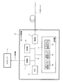
図1は、本実施形態に係る光線路監視システムの機能構成を示すシステム構成図である。本光線路監視システムは、図示するようにコンピュータA、光パルス試験機B(OTDR:Optical Time Domain Reflectometer)及び通信線Cから構成されている。
Hereinafter, an embodiment of the present invention will be described with reference to the drawings.
FIG. 1 is a system configuration diagram showing a functional configuration of the optical line monitoring system according to the present embodiment. The optical line monitoring system includes a computer A, an optical pulse tester B (OTDR: Optical Time Domain Reflectometer), and a communication line C as shown in the figure.
コンピュータAは、通信機能を備えた例えばパーソナルコンピュータ(PC)であり、通信線Cを介して光パルス試験機Bと通信を行うことにより光パルス試験機Bを制御する制御装置である。このコンピュータAには通信線Cを介して光パルス試験機Bを制御するための制御プログラムが予め搭載されている。コンピュータAは、上記制御プログラムに基づいて光パルス試験機Bと通信を行うことにより、当該光パルス試験機Bの動作を制御する。なお、コンピュータAの通信仕様は、後述する光パルス試験機Bの通信部1の通信仕様に合致したものであり、例えば信速度が100Mbps以上の高速イーサネット(登録商標)である。
The computer A is a personal computer (PC) having a communication function, for example, and is a control device that controls the optical pulse tester B by communicating with the optical pulse tester B via the communication line C. The computer A is preinstalled with a control program for controlling the optical pulse testing machine B via the communication line C. The computer A controls the operation of the optical pulse tester B by communicating with the optical pulse tester B based on the control program. The communication specification of the computer A matches the communication specification of the
光パルス試験機Bは、図示するように、通信部1、表示部2、測定部3、記憶部4及びCPU(Central Processing Unit)5がシステムバス6によって相互接続された光線路測定装置である。これら構成要素のうち、記憶部4、CPU5及びシステムバス6は、演算処理部を構成している。通信部1は、CPU5による制御下で、所定の通信仕様に基づいてコンピュータAと通信を行う。通信部1の通信仕様は、上述したように信速度が100Mbps以上の高速イーサネット(登録商標)である。
The optical pulse tester B is an optical line measurement device in which a
表示部2は、例えば液晶ディスプレイであり、CPU5による制御下で測定部3における測定波形や光パルス試験機Bの動作状態等を表示する。測定部3は、CPU5による制御下で、監視対象である光ファイバXの異常個所を特定する。この光ファイバXは所定の長さを有する光線路であり、測定部3は、このような光ファイバXに光パルスを順次出射して得られる後方散乱光の波形を測定データ(波形データ)として取得する。 The display unit 2 is, for example, a liquid crystal display, and displays a measurement waveform in the measurement unit 3, an operation state of the optical pulse tester B, and the like under the control of the CPU 5. Under the control of the CPU 5, the measurement unit 3 identifies an abnormal part of the optical fiber X that is a monitoring target. The optical fiber X is an optical line having a predetermined length, and the measurement unit 3 uses the waveform of backscattered light obtained by sequentially emitting optical pulses to the optical fiber X as measurement data (waveform data). get.
記憶部4は、上記測定データを記憶するための測定データ格納用メモリ4a、測定データに対応する基準データを記憶する基準データ格納用メモリ4b及び監視プログラムが予め記憶されたプログラム格納用メモリ4c等を備えている。これら各メモリのうち、測定データ格納用メモリ4aはRAM(Random Access Memory)であり、基準データ格納用メモリ4b及びプログラム格納用メモリ4cはROM(Read Only Memory)である。
The storage unit 4 includes a measurement
上記基準データは、光ファイバXの健全性が保障されているとき(例えば光ファイバXの敷設初期状態)に測定部3が光ファイバXから取得した後方散乱光の測定データ(波形データ)である。このような基準データは、予め取得されて基準データ格納用メモリ4bに記憶されている。
The reference data is measurement data (waveform data) of backscattered light acquired from the optical fiber X by the measurement unit 3 when the soundness of the optical fiber X is ensured (for example, the initial state of laying of the optical fiber X). . Such reference data is acquired in advance and stored in the reference
CPU5は、例えば64ビットCISC(Complex Instruction Set Computer)プロセッサであり、上記監視プログラムを実行することにより、システムバス6を介して上記通信部1、表示部2、測定部3及び記憶部4を統括的に制御する。システムバス6は、例えばPCI(Peripheral Component Interconnect)バスであり、通信部1、表示部2、測定部3、記憶部4及びCPU5を通信可能に相互接続する。
The CPU 5 is, for example, a 64-bit CISC (Complex Instruction Set Computer) processor, and controls the
また、通信線Cは、上記通信部1及びコンピュータAの通信仕様に準拠したものであり、例えばイーサネット(登録商標)の通信仕様に準拠したシリアル通信線である。なお、コンピュータA及び光パルス試験機Bの通信部1の通信仕様については、イーサネット(登録商標)に代えて、高速USB(Universal Serial Bus)等、他の通信仕様であっても良い。
The communication line C is compliant with the communication specifications of the
次に、このように構成された本光線路監視システムの動作について、図2に示すフローチャートに沿って詳しく説明する。なお、このフローチャートは、監視プログラムに基づくCPU5の処理手順(光パルス試験機Bの動作)を示すものである。 Next, operation | movement of this optical line monitoring system comprised in this way is demonstrated in detail along the flowchart shown in FIG. This flowchart shows the processing procedure of the CPU 5 (operation of the optical pulse tester B) based on the monitoring program.
本光線路監視システムにおいて、光パルス試験機Bは、測定開始要求(監視開始要求)を示す信号をコンピュータAから通信線Cを介して受信すると、監視プログラムに基づいて一連の監視動作を開始する。すなわち、光パルス試験機Bにおいて、通信部1は、測定開始要求をコンピュータAから受信すると、この測定開始要求をシステムバス6を介してCPU5に出力する。CPU5は、このようにして測定開始要求が入力されると(ステップS1)、リアルタイム測定開始指示をシステムバス6を介して測定部3に出力する(ステップS2)。
In this optical line monitoring system, when the optical pulse tester B receives a signal indicating a measurement start request (monitoring start request) from the computer A via the communication line C, it starts a series of monitoring operations based on the monitoring program. . That is, in the optical pulse tester B, when the
この結果、測定部3は、光ファイバXに光パルスを順次出射し、各パルスの後方散乱光を取得して平均化することにより測定データ(波形データ)を生成する。そして、測定部3は、上記測定データの生成、つまり光ファイバXの測定が完了すると、当該測定完了を示す割込み(測定完了割込み)をシステムバス6を介してCPU5に出力する。 As a result, the measurement unit 3 sequentially emits optical pulses to the optical fiber X, and acquires measurement data (waveform data) by acquiring and averaging the backscattered light of each pulse. Then, when the generation of the measurement data, that is, the measurement of the optical fiber X is completed, the measurement unit 3 outputs an interrupt (measurement completion interrupt) indicating the measurement completion to the CPU 5 via the system bus 6.
CPU5は、上記測定完了割込みが入力されると(ステップS3)、測定部3の測定データを記憶部4の測定データ格納用メモリ4aに転送させる(ステップS4)。すなわち、CPU5は、システムバス6を介して測定部3から測定データを読み出して測定データ格納用メモリ4aに記憶させる。そして、このような測定データの転送が完了すると、CPU5は、システムバス6を介して次のリアルタイム測定開始指示を測定部3に出力する(ステップS5)。この結果、測定部3は2回目の測定を介して次の測定データを生成するが、これとは別に、CPU5は、ステップS5以下の処理を行う。
When the measurement completion interrupt is input (step S3), the CPU 5 transfers the measurement data of the measurement unit 3 to the measurement
このような測定部3の測定動作と並行して、測定データ格納用メモリ4aの測定データ(リニアデータ)をdBデータ(対数データ)に変換する(ステップS6)。このdBデータは、後方散乱光の波形レベル(振幅)を対数値つまりdB(デシベル)で示す波形データである。このようなdBデータの生成が終了すると、CPU5は、dBデータに白色ノイズを除去する波形フィルタ処理を施し(ステップS7)、この波形フィルタ処理後のdBデータ(測定波形)と基準データ(基準波形)との差分である差分データ(差分波形)を生成する(ステップS8)。そして、CPU5は、この差分データにおいて、測定波形と基準波形との差が所定のしきい値を越える箇所を探索し光ファイバXの異常個所として特定する(ステップS9)。
In parallel with the measurement operation of the measurement unit 3, the measurement data (linear data) in the measurement
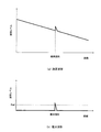
図3は、上記異常個所の特定処理を示す模式図であり、(a)は測定波形の模式図、(b)は差分波形の模式図である。図3(a)に示すように、光パルス試験機Bにおける測定波形は、距離に応じて応じて徐々にレベルが低下する異常個所におい波形レベルが急峻に変化するものとなる。基準波形は、異常が発生していない状態における測定波形なので、波形レベルの急峻な変化が存在しないものである。したがって、このような測定波形と基準波形との差分である差分波形は、図3(b)に示すように、異常個所以外では平坦であり、異常個所においてのみ波形レベルが急峻に変化するものとなる。このような差分波形をしきい値Refによって評価することにより、差分波形においてしきい値Refを越える箇所として異常個所を特定することができる。 FIGS. 3A and 3B are schematic diagrams showing the above-described abnormal part specifying process, in which FIG. 3A is a schematic diagram of a measurement waveform, and FIG. 3B is a schematic diagram of a differential waveform. As shown in FIG. 3 (a), the measured waveform in the optical pulse tester B has a sharply changed waveform level at an abnormal location where the level gradually decreases according to the distance. Since the reference waveform is a measurement waveform in a state where no abnormality has occurred, there is no sharp change in the waveform level. Therefore, as shown in FIG. 3B, the difference waveform that is the difference between the measurement waveform and the reference waveform is flat except for the abnormal part, and the waveform level changes sharply only in the abnormal part. Become. By evaluating such a differential waveform with the threshold value Ref, an abnormal part can be specified as a location exceeding the threshold value Ref in the differential waveform.
ここで、上記ステップS3〜S9の一連の処理は、測定部3の測定時間、つまり測定部3がリアルタイム測定開始指示を受信してから測定データを生成して測定完了割込みをCPU5に出力するまでの間にCPU5によって実行される。このような測定部3の測定時間は、例えば200msであり、測定部3が28回に亘る波形の平均化処理を行うのに必要な時間である。すなわち、CPU5は、次のリアルタイム測定開始指示に基づいて測定部3から次の測定完了割込みが入力されるまでに、ステップS3〜S9の処理を200ms内で完了する。 Here, the series of processing of steps S3 to S9 is performed until the measurement time of the measurement unit 3, that is, until the measurement unit 3 receives the real-time measurement start instruction, generates measurement data, and outputs a measurement completion interrupt to the CPU 5. It is executed by the CPU 5 during Measurement time of such measurement unit 3 is, for example, 200 ms, the time required to perform an averaging process of the waveform measurement unit 3 is over 2 8 times. That is, the CPU 5 completes the processes of steps S3 to S9 within 200 ms until the next measurement completion interrupt is input from the measurement unit 3 based on the next real-time measurement start instruction.
このような本実施形態によれば、CPU5は、測定データを測定部3から測定データ格納用メモリ4aに転送させると速やかに次の測定の開始指示を測定部3に出力して次の測定を開始させるので、デッドタイムを従来よりも短縮することが可能であり、よって短期的な異常現象における異常個所をより確実に特定することが可能である。
According to this embodiment, when the measurement data is transferred from the measurement unit 3 to the measurement
本実施形態によれば、例えば200ms毎に光ファイバXの測定が繰り返されることになるので、例えば異常が1秒程度しか継続しない短期的な異常現象について異常個所を十分に特定することが可能であり、よって従来の光線路監視システムよりも実用的な光線路監視装置及び光線路監視システムを提供することができる。 According to the present embodiment, since the measurement of the optical fiber X is repeated every 200 ms, for example, it is possible to sufficiently identify an abnormal part for a short-term abnormal phenomenon in which the abnormality continues only for about 1 second. Therefore, it is possible to provide an optical line monitoring device and an optical line monitoring system that are more practical than conventional optical line monitoring systems.
次に、本実施形態における処理動作の変形例について説明する。
上記動作説明では、測定データに基づくステップ4〜S9の処理を光パルス試験機BのCPU5が実行することを述べたが、CPU5の処理速度が遅い場合には、ステップS3〜S9の一連の処理を上述した200msの間に実行することができない場合が考えられる。本変形例は、このような状況に対処するために、測定データ格納用メモリ4aに記憶された測定データを通信線Cを介してコンピュータAに転送し、測定データに基づくステップ4〜S9の処理をコンピュータAで実行するものである。
Next, a modification of the processing operation in this embodiment will be described.
In the above description of the operation, it has been described that the processing of steps 4 to S9 based on the measurement data is executed by the CPU 5 of the optical pulse tester B. However, when the processing speed of the CPU 5 is low, a series of processing of steps S3 to S9 is performed. Can be executed during the above-mentioned 200 ms. In the present modification, in order to cope with such a situation, the measurement data stored in the measurement
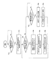
図4は、本変形例における光パルス試験機Bの動作を示すフローチャートである。なお、このフローチャートにおいて、ステップS1a〜S5aまでの処理は、図2に示したフローチャートにおけるステップS1〜S5までの処理と同一であり、ここでは説明を省略する。 FIG. 4 is a flowchart showing the operation of the optical pulse tester B in this modification. In this flowchart, the processing from step S1a to S5a is the same as the processing from step S1 to S5 in the flowchart shown in FIG. 2, and the description thereof is omitted here.
本変形例において、光パルス試験機BのCPU5は、次のリアルタイム測定開始指示を測定部3に出力すると(ステップS5a)、データ更新フラグを「ON」に設定する(ステップS6a)。また、CPU5は、コンピュータAから受信した通信要求割込みがシステムバス6を介して通信部1から入力されると(ステップS7a)、システムバス6を介して通信部1に制御指令を出力することにより、測定データ格納用メモリ4aに記憶された測定データを通信線Cを介してコンピュータAに転送させる(ステップS8a)。すなわち、通信部1は、制御指令がシステムバス6を介してCPU5から入力されると、測定データ格納用メモリ4aから測定データを読み出し、通信線Cを介してコンピュータAに送信する。
In this modification, when the CPU 5 of the optical pulse tester B outputs the next real-time measurement start instruction to the measurement unit 3 (step S5a), the data update flag is set to “ON” (step S6a). When the communication request interrupt received from the computer A is input from the
そして、CPU5は、測定データのコンピュータAへの転送が完了すると、上述したデータ更新フラグを「OFF」に設定する(ステップS9a)。すなわち、本変形例におけるデータ更新フラグは、測定データ格納用メモリ4aに記憶された測定データが既にコンピュータAに転送されたものであるか、あるいはコンピュータAに未転送のものであるかを示すものである。
Then, when the transfer of the measurement data to the computer A is completed, the CPU 5 sets the above-described data update flag to “OFF” (step S9a). That is, the data update flag in this modification indicates whether the measurement data stored in the measurement
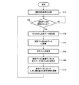
図5は、このような光パルス試験機Bの動作に対するコンピュータAの動作を示すフローチャートである。コンピュータAは、測定開始要求を光パルス試験機Bに送信すると(ステップSb1)、データ更新フラグの参照要求を通信線Cを介して光パルス試験機Bに送信してデータ更新フラグの設定状態を確認することにより測定データの更新状態(ステップSb2)。の上記データ更新フラグを参照することにより、光パルス試験機Bの測定データ格納用メモリ4aにおける測定データの更新状態を判断する(ステップSb2)。そして、コンピュータAは、測定データが更新されている場合には、通信線Cを介して測定データの転送要求を光パルス試験機Bに送信することにより、測定データ格納用メモリ4aの測定データを取得する(ステップSb3)。
FIG. 5 is a flowchart showing the operation of the computer A with respect to the operation of the optical pulse tester B. When the computer A transmits a measurement start request to the optical pulse tester B (step Sb1), the computer A transmits a data update flag reference request to the optical pulse tester B via the communication line C to change the setting state of the data update flag. By confirming, the measurement data is updated (step Sb2). By referring to the data update flag, the measurement data update state in the measurement
そして、コンピュータAは、測定データ(リニアデータ)をdBデータ(対数データ)に変換し(ステップSb4)、dBデータに白色ノイズを除去する波形フィルタ処理を施し(ステップSb5)、波形フィルタ処理後のdBデータ(つまり測定データ)と基準データとの差分データを生成する(ステップSb6)。そして、コンピュータAは、この差分データに基づいて、測定波形と基準波形との差が所定のしきい値以上の箇所を探索して光ファイバXの異常個所として特定する(ステップSb7)。 Then, the computer A converts the measurement data (linear data) into dB data (logarithmic data) (step Sb4), performs waveform filtering to remove white noise on the dB data (step Sb5), and performs waveform filtering processing. Difference data between the dB data (that is, measurement data) and the reference data is generated (step Sb6). Then, based on the difference data, the computer A searches for a location where the difference between the measurement waveform and the reference waveform is equal to or greater than a predetermined threshold value and identifies it as an abnormal location of the optical fiber X (step Sb7).
このような変形例によれば、コンピュータAと光パルス試験機Bとが処理を分散するので、光パルス試験機BのCPU5の処理速度が遅い場合であっても異常個所を十分に特定することが可能であり、よって従来の光線路監視システムよりも実用的な光線路監視装置及び光線路監視システムを提供することができる。 According to such a modification, since the computer A and the optical pulse tester B distribute the processing, even if the processing speed of the CPU 5 of the optical pulse tester B is slow, the abnormal part should be specified sufficiently. Therefore, it is possible to provide an optical line monitoring device and an optical line monitoring system that are more practical than conventional optical line monitoring systems.
なお、動作速度が遅いために、コンピュータAが図5に示した一連の処理を光パルス試験機Bにおける測定周期を阻害しない時間内に実行し得ないことも考えられる。このような場合には、コンピュータAは、図5におけるステップS4b〜S7bの処理を割愛することにより光パルス試験機Bで更新された測定データを順次取得してハードディスク装置等の記憶装置に測定データファイルとして順次記憶させる。そして、コンピュータAは、ユーザから入力された操作指示に基づいて光パルス試験機Bにおける測定動作とは切り離された別の時間で測定データファイルから測定データを読み出して異常個所の特定を行う。 Note that it is conceivable that the computer A cannot execute the series of processes shown in FIG. 5 within a time period that does not hinder the measurement cycle in the optical pulse tester B because the operation speed is low. In such a case, the computer A sequentially acquires the measurement data updated by the optical pulse tester B by omitting the processing of steps S4b to S7b in FIG. 5, and the measurement data is stored in a storage device such as a hard disk device. Store sequentially as a file. Then, the computer A reads out the measurement data from the measurement data file at a different time from the measurement operation in the optical pulse tester B based on the operation instruction input from the user, and identifies the abnormal part.
すなわち、異常個所の特定は、光ファイバXの監視中に必ずしもリアルタイムで行う必要はない場合がある。上述したように記憶装置に保存された測定データファイルを監視終了後に読み出して短期的な異常現象の発生と異常個所を特定することによっても十分に意義のある光ファイバXの監視を実現することができる。 That is, there is a case where it is not always necessary to identify the abnormal part in real time while monitoring the optical fiber X. As described above, the measurement data file stored in the storage device can be read after the monitoring is completed, and the occurrence of a short-term abnormal phenomenon and the location of the abnormal can be specified to realize sufficiently meaningful monitoring of the optical fiber X. it can.
また、上述したコンピュータAの場合と同様に、光パルス試験機Bにおいても図2に示したステップS5〜S9の処理を割愛し、光パルス試験機BのCPU5が測定部3から取得した測定データを測定データ格納用メモリ4aに測定データファイルとして順次記憶させ、監視が終了した後で測定データファイルから測定データを読み出してステップS5〜S9の処理を行うようにしても良い。
Similarly to the case of the computer A described above, in the optical pulse tester B, the processing of steps S5 to S9 shown in FIG. 2 is omitted, and the measurement data acquired by the CPU 5 of the optical pulse tester B from the measuring unit 3 is omitted. May be sequentially stored in the measurement
A…コンピュータ、B…光パルス試験機、C…通信線、1…通信部、2…表示部、3…測定部、4…記憶部、4a…測定データ格納用メモリ、4b…基準データ格納用メモリ、4c…プログラム格納用メモリ、5…CPU、6…システムバス A ... Computer, B ... Optical pulse tester, C ... Communication line, 1 ... Communication unit, 2 ... Display unit, 3 ... Measurement unit, 4 ... Storage unit, 4a ... Measurement data storage memory, 4b ... Reference data storage Memory, 4c ... Program storage memory, 5 ... CPU, 6 ... System bus
Claims (5)
該測定部の動作を制御すると共に、当該測定部から取得した前記測定データに所定の演算処理を施すことにより前記光線路の異常個所を特定する演算処理部とを備え、
前記演算処理部は、前記測定部から前記測定データを取得すると、前記測定部に次の測定の開始を指示することを特徴とする光線路監視装置。 A measurement unit that irradiates an optical pulse to be monitored with an optical pulse and generates measurement data based on backscattered light obtained by the optical pulse;
An operation processing unit that controls the operation of the measurement unit and identifies an abnormal part of the optical line by performing a predetermined operation process on the measurement data acquired from the measurement unit,
The said arithmetic processing part will instruct | indicate the start of the next measurement to the said measurement part, if the said measurement data are acquired from the said measurement part, The optical line monitoring apparatus characterized by the above-mentioned.
前記光線路測定装置は、監視対象である光線路に光パルスを照射すると共に当該光パルスによって得られる後方散乱光に基づいて測定データを生成し、
前記コンピュータは、前記光線路測定装置から測定データを取得し、前記測定データに所定の演算処理を施すことにより前記光線路の異常個所を特定する
ことを特徴とする光線路監視システム。 An optical line measuring device, a computer, and a communication line that connects the optical line measuring device and the computer so as to communicate with each other,
The optical line measuring device generates measurement data based on backscattered light obtained by irradiating the optical line to be monitored with an optical pulse and the optical pulse,
The said computer acquires measurement data from the said optical line measuring apparatus, and specifies the abnormal location of the said optical line by performing predetermined | prescribed arithmetic processing to the said measurement data. The optical line monitoring system characterized by the above-mentioned.
ことを特徴とする請求項4記載の光線路監視システム。 The arithmetic device stores and saves the measurement data acquired from the optical line measurement device in a measurement data file, and performs predetermined arithmetic processing on the measurement data in the measurement data file based on an instruction from the outside. The optical line monitoring system according to claim 4, wherein an abnormal portion of the optical line is specified.
Priority Applications (2)
| Application Number | Priority Date | Filing Date | Title |
|---|---|---|---|
| JP2008165761A JP5458515B2 (en) | 2008-06-25 | 2008-06-25 | Optical line monitoring device |
| US12/489,024 US8264677B2 (en) | 2008-06-25 | 2009-06-22 | Optical path monitoring device and optical path monitoring system |
Applications Claiming Priority (1)
| Application Number | Priority Date | Filing Date | Title |
|---|---|---|---|
| JP2008165761A JP5458515B2 (en) | 2008-06-25 | 2008-06-25 | Optical line monitoring device |
Publications (2)
| Publication Number | Publication Date |
|---|---|
| JP2010008143A true JP2010008143A (en) | 2010-01-14 |
| JP5458515B2 JP5458515B2 (en) | 2014-04-02 |
Family
ID=41446994
Family Applications (1)
| Application Number | Title | Priority Date | Filing Date |
|---|---|---|---|
| JP2008165761A Active JP5458515B2 (en) | 2008-06-25 | 2008-06-25 | Optical line monitoring device |
Country Status (2)
| Country | Link |
|---|---|
| US (1) | US8264677B2 (en) |
| JP (1) | JP5458515B2 (en) |
Cited By (5)
| Publication number | Priority date | Publication date | Assignee | Title |
|---|---|---|---|---|
| EP2357007A2 (en) | 2010-01-18 | 2011-08-17 | Seiko Epson Corporation | Liquid for discharge, method for discharging biospecimen, and compound |
| JP2012167935A (en) * | 2011-02-10 | 2012-09-06 | Anritsu Corp | Optical pulse tester event detection method and device and optical pulse testing device |
| JP2013040815A (en) * | 2011-08-12 | 2013-02-28 | Yokogawa Electric Corp | Optical pulse tester |
| JP2016516218A (en) * | 2013-05-24 | 2016-06-02 | ▲ホア▼▲ウェイ▼技術有限公司Huawei Technologies Co.,Ltd. | Optical branch assembly, passive optical network, and optical transmission method |
| US20210278314A1 (en) * | 2020-03-09 | 2021-09-09 | Verizon Patent And Licensing Inc. | Systems and methods for determining fiber cable geographic locations |
Families Citing this family (5)
| Publication number | Priority date | Publication date | Assignee | Title |
|---|---|---|---|---|
| CN102723989A (en) * | 2012-07-04 | 2012-10-10 | 慈溪市供电局 | Grading warning method and grading warning device for optical cable problems |
| AU2015243452A1 (en) * | 2014-04-11 | 2016-10-13 | Lockheed Martin Corporation | System and method for non-contact optical-power measurement |
| CN111884709B (en) * | 2020-07-20 | 2021-09-14 | 中铁第四勘察设计院集团有限公司 | Railway communication optical cable on-line monitoring system and method |
| US20230062982A1 (en) * | 2021-08-28 | 2023-03-02 | Subcom, Llc | Methods, mediums, and systems for testing fiber optic telecommunication systems |
| US11870488B2 (en) * | 2022-02-25 | 2024-01-09 | Ciena Corporation | Fast fiber transient locating systems and methods |
Citations (2)
| Publication number | Priority date | Publication date | Assignee | Title |
|---|---|---|---|---|
| JPH01141331A (en) * | 1987-11-27 | 1989-06-02 | Anritsu Corp | Optical pulse tester |
| JPH08163033A (en) * | 1994-12-06 | 1996-06-21 | Nippon Telegr & Teleph Corp <Ntt> | Method for testing optical line |
Family Cites Families (2)
| Publication number | Priority date | Publication date | Assignee | Title |
|---|---|---|---|---|
| JP2008020229A (en) | 2006-07-11 | 2008-01-31 | Yokogawa Electric Corp | Light pulse tester |
| JP2008122108A (en) * | 2006-11-08 | 2008-05-29 | Anritsu Corp | Optical pulse tester |
-
2008
- 2008-06-25 JP JP2008165761A patent/JP5458515B2/en active Active
-
2009
- 2009-06-22 US US12/489,024 patent/US8264677B2/en active Active
Patent Citations (2)
| Publication number | Priority date | Publication date | Assignee | Title |
|---|---|---|---|---|
| JPH01141331A (en) * | 1987-11-27 | 1989-06-02 | Anritsu Corp | Optical pulse tester |
| JPH08163033A (en) * | 1994-12-06 | 1996-06-21 | Nippon Telegr & Teleph Corp <Ntt> | Method for testing optical line |
Non-Patent Citations (1)
| Title |
|---|
| JPN6013061551; 佐藤 泰史、江間 伸明、播磨 洋介、佐藤 直人: '「光ファイバの敷設・保守用新型OTDR AQ7260シリーズ」' 横河技報 Vol. 49, No. 2, 20050420, p. 55-58 * |
Cited By (7)
| Publication number | Priority date | Publication date | Assignee | Title |
|---|---|---|---|---|
| EP2357007A2 (en) | 2010-01-18 | 2011-08-17 | Seiko Epson Corporation | Liquid for discharge, method for discharging biospecimen, and compound |
| JP2012167935A (en) * | 2011-02-10 | 2012-09-06 | Anritsu Corp | Optical pulse tester event detection method and device and optical pulse testing device |
| JP2013040815A (en) * | 2011-08-12 | 2013-02-28 | Yokogawa Electric Corp | Optical pulse tester |
| JP2016516218A (en) * | 2013-05-24 | 2016-06-02 | ▲ホア▼▲ウェイ▼技術有限公司Huawei Technologies Co.,Ltd. | Optical branch assembly, passive optical network, and optical transmission method |
| US9791628B2 (en) | 2013-05-24 | 2017-10-17 | Huawei Technologies Co., Ltd. | Optical branching assembly, passive optical network, and optical transmission method |
| US20210278314A1 (en) * | 2020-03-09 | 2021-09-09 | Verizon Patent And Licensing Inc. | Systems and methods for determining fiber cable geographic locations |
| US11802810B2 (en) * | 2020-03-09 | 2023-10-31 | Verizon Patent And Licensing Inc. | Systems and methods for determining fiber cable geographic locations |
Also Published As
| Publication number | Publication date |
|---|---|
| US8264677B2 (en) | 2012-09-11 |
| US20090323050A1 (en) | 2009-12-31 |
| JP5458515B2 (en) | 2014-04-02 |
Similar Documents
| Publication | Publication Date | Title |
|---|---|---|
| JP5458515B2 (en) | Optical line monitoring device | |
| US9984244B2 (en) | Controller, information processing apparatus, and recording medium | |
| US20140236914A1 (en) | Controller, information processing apparatus, and recording medium | |
| KR20170039311A (en) | Analog conversion device and programmable controller system | |
| TW201506611A (en) | Testing system and method for motherboard | |
| US20190041826A1 (en) | Tool management system, tool management method, and computer-readable storage medium storing computer program for allowing computer to act as tool management system | |
| JP6275009B2 (en) | Test apparatus and test program | |
| CN110958736B (en) | Black light lamp operation method and device, black light lamp and storage medium | |
| CN106644401A (en) | Test system and test method for testing semiconductor laser | |
| JP2006040122A (en) | Programmable controller | |
| CN113375807A (en) | Mainboard temperature detection method and device, storage medium and equipment | |
| JP2019162254A5 (en) | ||
| JP2018092403A (en) | Diagnostic apparatus and diagnostic method | |
| CN106979794B (en) | Sensor testing method and device | |
| JPWO2023119359A5 (en) | ||
| JP2009523240A (en) | Method and apparatus for quantitatively determining the end of an inspection interval | |
| JP2018206075A (en) | Processing device and computer program | |
| JP2020003282A5 (en) | ||
| CN110134108B (en) | Code defect testing method and device | |
| CN111858208B (en) | Standby function testing method, device, equipment and medium of processor chip | |
| JP2019087118A (en) | On-vehicle control device | |
| US20160132197A1 (en) | Blood purification device feedback method | |
| CN108733520B (en) | Inspection system, inspection apparatus, and inspection method | |
| JP2010038746A (en) | Ic tester diagnosing apparatus | |
| JP3214355U (en) | Half-break detector |
Legal Events
| Date | Code | Title | Description |
|---|---|---|---|
| A621 | Written request for application examination |
Free format text: JAPANESE INTERMEDIATE CODE: A621 Effective date: 20110311 |
|
| A977 | Report on retrieval |
Free format text: JAPANESE INTERMEDIATE CODE: A971007 Effective date: 20130717 |
|
| A131 | Notification of reasons for refusal |
Free format text: JAPANESE INTERMEDIATE CODE: A131 Effective date: 20130723 |
|
| A521 | Written amendment |
Free format text: JAPANESE INTERMEDIATE CODE: A523 Effective date: 20130821 |
|
| TRDD | Decision of grant or rejection written | ||
| A01 | Written decision to grant a patent or to grant a registration (utility model) |
Free format text: JAPANESE INTERMEDIATE CODE: A01 Effective date: 20131217 |
|
| A61 | First payment of annual fees (during grant procedure) |
Free format text: JAPANESE INTERMEDIATE CODE: A61 Effective date: 20131230 |
|
| R150 | Certificate of patent or registration of utility model |
Ref document number: 5458515 Country of ref document: JP Free format text: JAPANESE INTERMEDIATE CODE: R150 Free format text: JAPANESE INTERMEDIATE CODE: R150 |