JP2010007701A - Sliding type tripod constant velocity joint - Google Patents
Sliding type tripod constant velocity joint Download PDFInfo
- Publication number
- JP2010007701A JP2010007701A JP2008164967A JP2008164967A JP2010007701A JP 2010007701 A JP2010007701 A JP 2010007701A JP 2008164967 A JP2008164967 A JP 2008164967A JP 2008164967 A JP2008164967 A JP 2008164967A JP 2010007701 A JP2010007701 A JP 2010007701A
- Authority
- JP
- Japan
- Prior art keywords
- tripod
- outer ring
- constant velocity
- pair
- power transmission
- Prior art date
- Legal status (The legal status is an assumption and is not a legal conclusion. Google has not performed a legal analysis and makes no representation as to the accuracy of the status listed.)
- Granted
Links
Images


Landscapes
- Rolling Contact Bearings (AREA)
Abstract
Description
本発明は、摺動式トリポード型等速ジョイントに関するものである。 The present invention relates to a sliding tripod type constant velocity joint.
従来の摺動式トリポード型等速ジョイントとして、例えば、特開2000−256694号公報(特許文献1)に記載されたものがある。特許文献1に記載の摺動式トリポード型等速ジョイントは、トリポード軸部が円柱状をなしており、ローラの内周面が円筒状をなしている。この場合、ローラは、常にトリポード軸部に対して同軸上に位置している。そのため、ジョイント角を付加したときに、ローラが軌道溝(ローラ溝)を転動しようとする方向と、軌道溝の延びる方向とが一致しない状態となる。このことにより、ローラと軌道溝との間に滑りが発生し、その結果、ジョイント軸方向に誘起スラスト力が発生する。この誘起スラスト力は、車体の振動や騒音の発生原因となる。
As a conventional sliding tripod type constant velocity joint, for example, there is one described in Japanese Unexamined Patent Publication No. 2000-256694 (Patent Document 1). In the sliding tripod type constant velocity joint described in
そこで、誘起スラスト力を低減するために、例えば、特開2006−162056号公報(特許文献2)に記載されたものがある。特許文献2に記載の摺動式トリポード型等速ジョイントにおいて、トリポード軸部の外周面が球面凸状をなし、それに当接するローラユニットを構成する内ローラの内周面が円筒状をなしている。これにより、トリポード軸部がローラユニットに対して揺動可能となり、ローラユニットを構成する外ローラが軌道溝を転動しようとする方向と、軌道溝の延びる方向とが常に一致できるため、外ローラと軌道溝との間に滑りが発生しないようにできる。その結果、誘起スラスト力を低減することができる。 Therefore, in order to reduce the induced thrust force, for example, there is one described in Japanese Patent Laid-Open No. 2006-162056 (Patent Document 2). In the sliding tripod type constant velocity joint described in Patent Document 2, the outer peripheral surface of the tripod shaft portion has a spherical convex shape, and the inner peripheral surface of the inner roller that constitutes the roller unit that contacts the outer peripheral surface has a cylindrical shape. . As a result, the tripod shaft portion can swing with respect to the roller unit, and the direction in which the outer roller constituting the roller unit tries to roll on the raceway groove can always coincide with the direction in which the raceway groove extends. It is possible to prevent slippage between the rail and the raceway groove. As a result, the induced thrust force can be reduced.
また、他の構成として、特開昭63−163031号公報(特許文献3)および特許第2763624号公報(特許文献4)に記載されたものがある。特許文献3に記載の摺動式トリポード型等速ジョイントは、トリポード軸部の外側に一対の中間部材を設け、それぞれの中間部材と軌道溝の側面との間にニードルを配置した構成からなる。また、特許文献4に記載の摺動式トリポード型等速ジョイントは、トリポード軸部の外周に筒状の一体的な中間部材を設け、一体的な中間部材の外周面をニードルが循環可能とし、且つ、ニードルが中間部材と軌道溝の側面とに沿って転動する構成からなる。
ここで、特許文献2に記載の等速ジョイントにおいては、ジョイント角を付加したときには、トリポード軸部がローラユニットに対して、トリポード軸部の軸方向に摺動する。そのため、これまでの摺動式トリポード型等速ジョイントでは、内ローラの内周面のうちトリポード軸部に当接する位置が変化する。これにより、ローラユニットが外輪の軌道溝の延びる方向回りに揺動するように動作する。そのため、ローラユニットのうち、外輪の軌道溝と動力伝達を行っている部位の背面側が、軌道溝に当接し、ローラユニットと軌道溝との間にて摩擦力が発生し、その結果、誘起スラスト力が大きくなるおそれがある。また、軌道溝とローラユニットとの隙間を大きくとることで、背面側の当接を防ぐことが考えられるが、このような構成ではローラユニットの回転ガタが大きくなるおそれがある。 Here, in the constant velocity joint described in Patent Document 2, when the joint angle is added, the tripod shaft portion slides in the axial direction of the tripod shaft portion with respect to the roller unit. Therefore, in the conventional sliding tripod type constant velocity joint, the position of the inner peripheral surface of the inner roller that contacts the tripod shaft portion changes. As a result, the roller unit operates so as to swing around the direction in which the raceway groove of the outer ring extends. For this reason, the back side of the portion of the roller unit that is transmitting power to the outer raceway groove contacts the raceway groove, and a frictional force is generated between the roller unit and the raceway groove. There is a risk of increased strength. In addition, it is conceivable to prevent the contact on the rear side by increasing the clearance between the raceway groove and the roller unit. However, in such a configuration, there is a possibility that the rotation play of the roller unit is increased.
また、特許文献3に記載の等速ジョイントにおいては、ジョイント角が小さい場合においては、ニードルが軌道溝を転動する状態となる。しかし、ニードルが軌道溝の延びる方向に有限の個数に制限されているため、ジョイント角を大きくすると、ニードルが軌道溝および中間部材に対して滑りを生じる。この滑りが、スラスト力を誘起する。 Moreover, in the constant velocity joint described in Patent Document 3, when the joint angle is small, the needle rolls in the raceway groove. However, since the number of needles is limited to a finite number in the direction in which the raceway grooves extend, if the joint angle is increased, the needles slip relative to the raceway grooves and the intermediate member. This slip induces a thrust force.
一方、特許文献4に記載の等速ジョイントにおいては、ニードルが循環するような構成であるため、ニードルが軌道溝および中間部材に対して転動する状態となり、滑りが生じることを防止できる。しかし、中間部材が一体的な構成であるため、特許文献2に記載の等速ジョイントにおける問題と同様の問題を生じる。つまり、動力伝達を行っている部位の背面側において、ニードルを介して中間部材が外輪に力を付与する状態が発生し得る。このように、背面側における力の発生が、スラスト力を誘起する。 On the other hand, in the constant velocity joint described in Patent Document 4, since the needle is configured to circulate, the needle rolls with respect to the raceway groove and the intermediate member, and slippage can be prevented. However, since the intermediate member has an integral structure, a problem similar to the problem in the constant velocity joint described in Patent Document 2 occurs. That is, a state in which the intermediate member applies a force to the outer ring via the needle can occur on the back side of the portion where the power is transmitted. Thus, the generation of force on the back side induces a thrust force.
本発明は、このような事情に鑑みてなされたものであり、外輪の軌道溝に当接する部材が軌道溝に対して確実に転動する構成とし、且つ、トリポード軸部がローラユニットに対してトリポード軸部の軸方向に摺動する場合であっても、ローラユニットの背面側が軌道溝に大きな力を付与することを防止できる摺動式トリポード型等速ジョイントを提供することを目的とする。 The present invention has been made in view of such circumstances, and the member that contacts the raceway groove of the outer ring is configured to roll reliably with respect to the raceway groove, and the tripod shaft portion is relative to the roller unit. An object of the present invention is to provide a sliding tripod type constant velocity joint capable of preventing the back side of the roller unit from applying a large force to the raceway groove even when sliding in the axial direction of the tripod shaft portion.
(手段1)手段1に係る摺動式トリポード型等速ジョイントは、
筒状からなり、内周面に外輪回転軸方向に延びる3本の軌道溝が形成された外輪と、
シャフトに連結されるボス部、および、前記ボス部の外周面からそれぞれ前記ボス部の径方向外方に延びるように立設されそれぞれの前記軌道溝に挿入される3本のトリポード軸部を備えるトリポードと、
前記軌道溝の側面の両側から前記トリポード軸部を挟むように配置され、且つ、前記トリポード軸部に対して揺動可能に設けられる一対の中間部材と、
前記軌道溝の側面と前記一対の中間部材の前記軌道溝の側面に対向する動力伝達面との間に、前記軌道溝の側面に沿って転動可能に設けられる複数の転動体と、
前記転動体が前記一対の中間部材の外周を循環可能となるように前記転動体を支持する保持器と、
を備えることを特徴とする。
(Means 1) The sliding tripod type constant velocity joint according to
An outer ring having a cylindrical shape and formed with three raceway grooves extending in the outer ring rotation axis direction on the inner peripheral surface;
A boss portion coupled to the shaft, and three tripod shaft portions that are erected so as to extend radially outward of the boss portion from the outer peripheral surface of the boss portion and are inserted into the raceway grooves, respectively. Tripod,
A pair of intermediate members disposed so as to sandwich the tripod shaft from both sides of the side surface of the raceway groove, and provided so as to be swingable with respect to the tripod shaft;
A plurality of rolling elements provided between the side surface of the raceway groove and a power transmission surface facing the side surface of the raceway groove of the pair of intermediate members so as to roll along the side surface of the raceway groove;
A cage that supports the rolling elements such that the rolling elements can circulate around the outer periphery of the pair of intermediate members;
It is characterized by providing.
本発明によれば、転動体が軌道溝を転動可能となるように、一対の中間部材の外周を循環する構成であるため、外輪の軌道溝に当接する部材が軌道溝に対して確実に転動する構成となる。従って、外輪の軌道溝に当接する部材が、軌道溝に対して滑りが生じることを防止できるため、このことによる誘起スラスト力の発生を防止できる。 According to the present invention, since the rolling element is configured to circulate around the outer periphery of the pair of intermediate members so that the rolling element can roll on the raceway groove, the member that contacts the raceway groove of the outer ring is reliably attached to the raceway groove. It is configured to roll. Therefore, since the member that contacts the raceway groove of the outer ring can be prevented from slipping with respect to the raceway groove, the generation of the induced thrust force due to this can be prevented.
また、特許文献2、4の等速ジョイントのローラユニットは、動力伝達時にトリポード軸部が摺動して内ローラの内周面のうちトリポード軸部に当接する位置が変化するので、外輪の軌道溝の延びる方向回りに一体的に揺動し、動力伝達を行っている部位の背面側で軌道溝と当接するため、上記のような問題が発生していた。 Further, the roller unit of the constant velocity joint of Patent Documents 2 and 4 changes the position where the tripod shaft portion slides during power transmission and contacts the tripod shaft portion on the inner peripheral surface of the inner roller, so that the outer ring raceway is changed. The above-mentioned problem has occurred because the rocker integrally swings around the direction in which the groove extends and contacts the raceway groove on the back side of the portion where power is transmitted.
これに対して、本発明は、トリポード軸部を挟むように配置され、且つ、トリポード軸部に揺動可能に設けられる一対の中間部材を備えている。つまり、一対の中間部材は、それぞれ独立している。このようにすることで、動力伝達側で発生するトリポード軸部による荷重位置が変化したとしても、動力伝達側の中間部材の動作が、その背面側の中間部材の動作へ影響を及ぼすことがない。従って、ローラユニットの背面側が軌道溝に大きな力を付与することを防止できるので、誘起スラスト力の発生を大幅に低減することができる。 On the other hand, the present invention includes a pair of intermediate members that are disposed so as to sandwich the tripod shaft portion and are swingably provided on the tripod shaft portion. That is, the pair of intermediate members are independent of each other. By doing in this way, even if the load position by the tripod shaft part generated on the power transmission side changes, the operation of the intermediate member on the power transmission side does not affect the operation of the intermediate member on the back surface side. . Accordingly, since it is possible to prevent the back side of the roller unit from applying a large force to the raceway groove, the generation of the induced thrust force can be greatly reduced.
ここで、「ローラユニット」とは、トリポード軸部からの動力を外輪の軌道溝に伝達する部材から構成され、例えば、特許文献2のトリポード型等速ジョイントにおけるローラユニットは、内ローラ、外ローラ、ローラ支持体およびスナップリングなどで構成される。本発明のトリポード型等速ジョイントにおけるローラユニットは、中間部材、転動体および保持器から構成される。 Here, the “roller unit” is composed of a member that transmits the power from the tripod shaft to the raceway groove of the outer ring. For example, the roller unit in the tripod type constant velocity joint of Patent Document 2 includes an inner roller and an outer roller. And a roller support and a snap ring. The roller unit in the tripod type constant velocity joint of the present invention includes an intermediate member, a rolling element, and a cage.
(手段2)手段1の摺動式トリポード型等速ジョイントにおいて、
前記トリポード軸部の外周面は球面凸状であり、
前記外輪回転軸と前記シャフト回転軸が一致している姿勢において、
前記転動体のトリポード軸方向の幅中心を通りトリポード軸と直交する平面におけるトリポード軸上の点と、前記外輪回転軸との距離を外輪PCRとし、
前記トリポード軸部の外周面の曲率中心と、前記シャフト回転軸との距離をトリポードPCRとし、
前記トリポードPCRは、前記外輪PCRより大きく設定されるとよい。
(Means 2) In the sliding tripod type constant velocity joint of
The outer peripheral surface of the tripod shaft portion is a spherical convex shape,
In a posture in which the outer ring rotation axis and the shaft rotation axis coincide with each other,
A distance between a point on the tripod axis in a plane passing through the center of the tripod axis direction of the rolling element and orthogonal to the tripod axis and the outer ring rotation axis is defined as an outer ring PCR;
The distance between the center of curvature of the outer peripheral surface of the tripod shaft and the shaft rotation axis is defined as tripod PCR,
The tripod PCR may be set larger than the outer ring PCR.
ここで、仮に、外輪回転軸とシャフト回転軸が一致する姿勢で外輪PCR(ピッチ円半径)とトリポードPCR(ピッチ円半径)とを一致するように設定した場合には、ジョイント角を付加して動力伝達した際に、トリポード軸部とローラユニットの接触領域がローラユニットの幅方向に摺動し、その摺動幅の中心がローラユニットに対して外輪径方向内側に位置することになる。そのため、例えば、転動体に球体を適用した場合には、トリポード軸部のローラユニットに対する荷重位置がローラユニットの幅中心から離れるほど、回転ガタが増加するおそれがある。また、転動体にニードルを適用した場合には、ニードルが偏磨耗するおそれがある。 Here, if the outer ring PCR (pitch circle radius) and the tripod PCR (pitch circle radius) are set to match in a posture where the outer ring rotation axis and the shaft rotation axis match, a joint angle is added. When power is transmitted, the contact area between the tripod shaft and the roller unit slides in the width direction of the roller unit, and the center of the sliding width is located on the inner side in the outer ring radial direction with respect to the roller unit. Therefore, for example, when a sphere is applied to the rolling element, the backlash may increase as the load position of the tripod shaft portion with respect to the roller unit increases from the width center of the roller unit. Moreover, when a needle is applied to a rolling element, there is a possibility that the needle will wear unevenly.
そこで、トリポードPCRを外輪PCRより大きく設定することで、所定のジョイント角を付加して動力伝達した際に、トリポード軸部とローラユニットの接触領域の摺動幅の中心がローラユニットに対して外輪径方向中央付近に位置することができる。結果として、回転ガタを低減することができ、且つ、ニードルなどの転動体が偏磨耗することを防ぐことができる。ただし、トリポードPCRと外輪PCRとが一致する場合に比べて、トリポードPCRが外輪PCRより大きい場合には、トリポード軸部によるローラユニットへの荷重位置が外輪径方向外側に位置する。そのため、ローラユニットが動力伝達の背面側にて、外輪の軌道溝に接触する可能性が高まる。しかし、一対の中間部材が独立しているため、動力伝達の背面側における軌道溝とローラユニットとの隙間を大きくとることなく、両者の接触を回避できる。 Therefore, by setting the tripod PCR larger than the outer ring PCR, when the power is transmitted with a predetermined joint angle, the center of the sliding width of the contact area between the tripod shaft and the roller unit is relative to the roller unit. It can be located near the center in the radial direction. As a result, rotation backlash can be reduced, and uneven rolling of rolling elements such as needles can be prevented. However, when the tripod PCR is larger than the outer ring PCR as compared with the case where the tripod PCR and the outer ring PCR match, the load position on the roller unit by the tripod shaft portion is located on the outer side in the outer ring radial direction. Therefore, the possibility that the roller unit contacts the raceway groove of the outer ring on the back side of the power transmission is increased. However, since the pair of intermediate members are independent, it is possible to avoid contact between the raceway groove and the roller unit on the rear side of the power transmission without taking a large gap.
(手段3)手段1または2の摺動式トリポード型等速ジョイントにおいて、
前記一対の中間部材には、循環する前記転動体を前記動力伝達面へ円滑に接触案内するように、前記動力伝達面に対して滑らかな中間部材導入面を形成するとよい。
(Means 3) In the sliding tripod type constant velocity joint of
The pair of intermediate members may be formed with a smooth intermediate member introduction surface with respect to the power transmission surface so as to smoothly contact and guide the circulating rolling elements to the power transmission surface.
ここで、一対の中間部材のうち動力伝達を行っている側の部材は、トリポード軸部と外輪に対して位置決めされる。一方、保持器は、動力伝達には寄与しない部材であるため、保持器の位置は安定しているものではない。そのため、位置が安定していない保持器から、中間部材の動力伝達面へ、転動体を所定の姿勢で進入させることは容易ではない。そこで、中間部材の動力伝達面と、その動力伝達面へ転動体を進入する中間部材導入面とを同一部材に形成することで、動力伝達面へ進入する転動体の姿勢を安定して整えることができる。 Here, of the pair of intermediate members, the member performing power transmission is positioned with respect to the tripod shaft portion and the outer ring. On the other hand, since the cage is a member that does not contribute to power transmission, the position of the cage is not stable. Therefore, it is not easy to allow the rolling elements to enter the power transmission surface of the intermediate member from a cage whose position is not stable in a predetermined posture. Accordingly, the power transmission surface of the intermediate member and the intermediate member introduction surface that allows the rolling element to enter the power transmission surface are formed on the same member, so that the posture of the rolling element that enters the power transmission surface can be stably adjusted. Can do.
(手段4)手段3の摺動式トリポード型等速ジョイントにおいて、
前記保持器により循環する前記転動体の軌跡である循環路は、
前記動力伝達面を移動する前記転動体の循環路であって前記動力伝達面に倣う第一の循環路と、
前記中間部材導入面を移動する前記転動体の循環路であって前記中間部材導入面に倣い且つ前記第一の循環路に滑らかに接続する第二の循環路と、
前記第二の循環路のうち前記第一の循環路と反対側端部に滑らかに接続する第三の循環路と、を有するとよい。
(Means 4) In the sliding tripod type constant velocity joint of means 3,
The circulation path which is the locus of the rolling elements circulated by the cage is
A first circulation path that is a circulation path of the rolling element that moves on the power transmission surface and follows the power transmission surface;
A second circulation path that is a circulation path of the rolling element that moves on the intermediate member introduction surface and that follows the intermediate member introduction surface and is smoothly connected to the first circulation path;
It is good to have a 3rd circulation path smoothly connected to an end part on the opposite side to said 1st circulation path among said 2nd circulation paths.
ここで、中間部材導入面は、軌道溝との間で動力を伝達する部位ではないため、中間部材導入面を移動する転動体にそれほど大きな荷重が付加されていない。そのため、第三の循環路から中間部材導入面に倣う第二の循環路へ転動体を安定して進入させることが可能となる。結果として、第三の循環路から第二の循環路へ、さらに、第二の循環路から動力伝達面に倣う第一の循環路へ、転動体を滑らかに移動させることができる。 Here, since the intermediate member introduction surface is not a part that transmits power to or from the raceway groove, a very large load is not applied to the rolling elements that move on the intermediate member introduction surface. Therefore, it is possible to stably cause the rolling elements to enter the second circulation path following the intermediate member introduction surface from the third circulation path. As a result, the rolling elements can be smoothly moved from the third circulation path to the second circulation path, and further from the second circulation path to the first circulation path following the power transmission surface.
(手段5)手段1〜4のいずれかの摺動式トリポード型等速ジョイントにおいて、
前記保持器は、前記一対の中間部材に対して動力伝達方向に規制されていないようにするとよい。
(Means 5) In the sliding tripod type constant velocity joint of any one of
It is preferable that the cage is not restricted in the power transmission direction with respect to the pair of intermediate members.
例えば、一対の中間部材のうち軌道溝の側面に対向する全ての面(動力伝達面および中間部材導入面を含む)と保持器との間に隙間を設ける。これにより、保持器が、動力伝達の背面側において、転動体が外輪の軌道溝へ力を付与するように作用することを防止できる。従って、確実に、上記効果を奏することができる。 For example, a clearance is provided between all the surfaces (including the power transmission surface and the intermediate member introduction surface) facing the side surface of the raceway groove in the pair of intermediate members and the cage. Thereby, it can prevent that a rolling element acts so that a rolling element may provide force to the raceway groove of an outer ring in the back side of power transmission. Therefore, the above-described effect can be surely achieved.
(手段6)手段1〜5のいずれかの摺動式トリポード型等速ジョイントにおいて、
前記トリポード軸部の外周面は、球面凸状であり、
前記一対の中間部材の内面は、前記トリポード軸部の外周面に嵌合される球面凹状であってもよい。
(Means 6) In the sliding tripod constant velocity joint of any one of
The outer peripheral surface of the tripod shaft portion is a spherical convex shape,
The inner surfaces of the pair of intermediate members may be spherical concave shapes fitted to the outer peripheral surface of the tripod shaft portion.
トリポード軸部と一対の中間部材は揺動可能に球面嵌合などの構成とすることにより、中間部材の単位面積当たりの荷重(面圧)が低減され、中間部材の耐久性を向上させることができる。また、中間部材は、摺動するトリポード軸部に従動するので、トリポード軸部に対して位置が定まり安定的に動力伝達することができる。さらに、本発明では、一対の中間部材はトリポード軸部を挟むように配置されるので、その内面を全て球面凹状に容易に形成することができる。従って、トリポード軸部と一対の中間部材との動力伝達面積を増加することができ、また、トリポード軸部と中間部材がアンギュラコンタクトする場合にはアンギュラコンタクトする2箇所の点を更に離間し安定化を図ることができる。 By configuring the tripod shaft portion and the pair of intermediate members to be swingable so as to be spherically fitted, the load (surface pressure) per unit area of the intermediate member can be reduced, and the durability of the intermediate member can be improved. it can. Further, since the intermediate member is driven by the sliding tripod shaft portion, the position is determined with respect to the tripod shaft portion, and power can be stably transmitted. Furthermore, in the present invention, since the pair of intermediate members are arranged so as to sandwich the tripod shaft portion, all the inner surfaces thereof can be easily formed into a spherical concave shape. Therefore, the power transmission area between the tripod shaft part and the pair of intermediate members can be increased, and when the tripod shaft part and the intermediate member make an angular contact, the two points where the angular contact comes into contact are further separated and stabilized. Can be achieved.
(手段7)手段1〜5の摺動式トリポード型等速ジョイントにおいて、
前記転動体は、円柱状のニードルであり、
前記外輪回転軸と前記シャフト回転軸が一致している姿勢において、
前記保持器は、前記ニードルの円柱軸方向が前記トリポード軸方向と平行となるように前記ニードルを支持し、
前記一対の中間部材は、前記ニードルに対し前記外輪径方向に摺動可能な前記動力伝達面を形成してもよい。
(Means 7) In the sliding tripod type constant velocity joint of
The rolling element is a cylindrical needle,
In a posture in which the outer ring rotation axis and the shaft rotation axis coincide with each other,
The retainer supports the needle such that the cylindrical axis direction of the needle is parallel to the tripod axis direction,
The pair of intermediate members may form the power transmission surface slidable in the outer ring radial direction with respect to the needle.
これにより、ニードルが外輪の軌道溝側面に対し円柱軸方向に亘り当接して動力伝達するので、ローラユニットは全体として回転ガタが小さく、安定した動力伝達ができる。 Thereby, the needle abuts against the raceway side surface of the outer ring in the cylindrical axis direction to transmit power, so that the roller unit as a whole has a small rotational backlash and can stably transmit power.
(手段8)手段1〜5の摺動式トリポード型等速ジョイントにおいて、
また、転動体は、球状またはバレル状コロであり、
外輪回転軸とシャフト回転軸が一致している姿勢において、
一対の中間部材は、転動体に対し外輪径方向に揺動可能な動力伝達面を形成されてもよい。
(Means 8) In the sliding tripod type constant velocity joint of the
Further, the rolling element is a spherical or barrel-shaped roller,
In a posture where the outer ring rotation axis and the shaft rotation axis match,
The pair of intermediate members may be formed with a power transmission surface capable of swinging in the outer ring radial direction with respect to the rolling elements.
転動体が球状の場合は、単純な形状で剛性が高く最も滑らかに循環可能なので、大きな動力でも安定して伝達することができる。また、転動体がバレル状コロの場合は、球状に比してトリポード軸直交方向幅を小さくできるので、ローラユニットの全幅を縮小化することができる。さらに、中間部材は、転動体に対し外輪径方向に揺動可能とすることで、摺動するトリポード軸部の位置に応じて転動体へ動力を伝達することができる。ここで、バレル状コロとは、柱状であり、柱延伸直交方向に切断した断面が円形からなり、柱延伸方向に切断した断面における外周面に相当する部分が円弧凸状となっている。 When the rolling element is spherical, it has a simple shape and has the highest rigidity and can be circulated most smoothly, so that even a large amount of power can be transmitted stably. Further, when the rolling element is a barrel-shaped roller, the width in the direction orthogonal to the tripod axis can be made smaller than that of the spherical shape, so that the entire width of the roller unit can be reduced. Further, the intermediate member can swing in the outer ring radial direction with respect to the rolling element, so that power can be transmitted to the rolling element according to the position of the sliding tripod shaft portion. Here, the barrel-shaped roller has a columnar shape, and a cross section cut in the direction perpendicular to the column stretching is circular, and a portion corresponding to the outer peripheral surface in the cross section cut in the column stretching direction is a circular arc.
以下、本発明の摺動式トリポード型等速ジョイント(以下、単に「等速ジョイント」と称する。)を具体化した実施形態について図面を参照しつつ説明する。ここで、本実施形態の等速ジョイントは、車両の動力伝達シャフトの連結に用いる場合を例に挙げて説明する。例えば、ディファレンシャルギヤに連結された軸部とドライブシャフトの中間シャフトとの連結部位に用いる場合である。 Hereinafter, an embodiment in which a sliding tripod type constant velocity joint of the present invention (hereinafter simply referred to as “constant velocity joint”) is embodied will be described with reference to the drawings. Here, the case where the constant velocity joint of this embodiment is used for connection of a power transmission shaft of a vehicle will be described as an example. For example, it is a case where it uses for the connection part of the axial part connected with the differential gear, and the intermediate shaft of a drive shaft.
<第一実施形態>
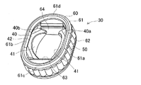
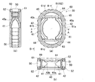
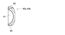
第一実施形態の等速ジョイント1について、図1〜図8を参照して説明する。図1は、第一実施形態の等速ジョイント1の一部の組付け状態における、外輪10の開口側から見た図である。図2は、等速ジョイント1の一部の径方向断面図である。図3は、ローラユニット30の斜視図である。図4(a)は、ローラユニット30の平面図であり、図4(b)は、ローラユニット30のA−A断面図(短径側の断面図)であり、図4(c)は、ローラユニット30のB−B部分断面図(長径側の部分断面を含む図)である。図5は、一対の中間部材40の一つの斜視図である。図6(a)は、中間部材40の正面図であり、図6(b)は、中間部材40のE−E部分断面図であり、図6(c)は、中間部材40のF方向矢視図であり、図6(d)は、中間部材40のG−G断面図であり、図6(e)は、中間部材40のH−H断面図である。図7は、保持器60の斜視図である。図8(a)は、保持器60の平面図であり、図8(b)は、保持器60のC−C断面図(短径側の断面図)であり、図8(c)は、保持器60のD−D断面図(長径側の部分断面を含む図)である。
<First embodiment>
The constant velocity joint 1 of 1st embodiment is demonstrated with reference to FIGS. FIG. 1 is a view seen from the opening side of the
図1および図2に示すように、等速ジョイント1は、外輪10と、トリポード20と、ローラユニット30とから構成される。
As shown in FIGS. 1 and 2, the constant velocity joint 1 includes an
外輪10は、筒状(例えば、有底筒状)に形成されており、一端側がディファレンシャルギヤ(図示せず)に連結されている。そして、外輪10の筒状部分の内周面には、外輪軸方向(図1の前後方向)に延びる軌道溝11が、外輪軸の周方向に等間隔に3本形成されている。各軌道溝11における溝延伸方向に直交する断面形状が、コの字形をなしている。つまり、各軌道溝11は、ほぼ平面状に形成された溝底面と、溝底面に直交する平面状に形成され且つそれぞれ平行に対向する側面とを備える。
The
さらに、この軌道溝11の両開口縁には、軌道溝11の開口幅を狭める係止突起12が形成されている。この係止突起12は、後述するローラユニット30を構成する保持器60の位置を規制するためのものである。つまり、係止突起12により、保持器60が軌道溝11の内部に常に位置するようになる。
Further, locking
トリポード20は、外輪10の筒状部分の内側に配置されている。このトリポード20は、ボス部21と、3本のトリポード軸部22とを備える。ボス部21は、筒状からなり、内周側には内周スプライン21aが形成されている。この内周スプライン21aは、中間シャフト(図示せず)の端部の外周スプラインに嵌合連結される。また、ボス部21の外周面は、ほぼ球面凸状に形成されている。
The
それぞれのトリポード軸部22は、ボス部21の外周面からそれぞれボス部21の径方向外方に延びるように立設されている。これらのトリポード軸部22は、ボス部21の周方向に等間隔(120deg間隔)に形成されている。そして、それぞれのトリポード軸部22の少なくとも先端部は、外輪10のそれぞれの軌道溝11内に挿入されている。それぞれのトリポード軸部22の外周面は、球面凸状に形成されている。
Each
ローラユニット30は、図3および図4に示すように、全体形状としては環状からなり、トリポード軸部22の外周側に配置されている。さらに、ローラユニット30は、軌道溝11が延びる方向に移動可能となるように、軌道溝11に嵌合されている。このローラユニット30は、中間部材40と、複数の転動体50と、保持器60とから構成される。
As shown in FIGS. 3 and 4, the
中間部材40の全体形状としての外形は、ほぼ矩形に形成されている。さらに、中間部材40を全体としてみた場合に、中間部材40の中央には、円形孔に相当する部分が形成されている。この中間部材40は、一対の部材40a、40bからなる。一対の中間部材40a、40bは、トリポード軸部22の中心軸(「トリポード軸」とも称する)および中間シャフトの回転軸を通る平面に対して対称な形状からなるように別体で構成され、それぞれ独立している。そして、一対の中間部材40a、40bは、図2に示すように、軌道溝11の側面の両側からトリポード軸部22を挟むように配置されている。つまり、両中間部材40a、40bは、動力伝達方向(外輪回転軸回りまたは中間シャフト回転軸回りの方向)の両側からトリポード軸部22を挟むように配置されている。そして、一対の中間部材40a、40bは、トリポード軸部22に対して、外輪10の回転軸方向に揺動可能であり、且つ、外輪10の周方向に揺動可能に設けられている。
The outer shape of the
各中間部材40a、40bの詳細な形状について図5および図6(a)〜(d)を参照して説明する。各中間部材40a、40bの表面は、トリポード接触面41と、動力伝達面42と、中間部材導入面43と、軸方向端面44、45を有している。ここで、一対の中間部材40a、40bを一体として見た場合に、トリポード接触面41が内面を形成し、動力伝達面42、中間部材導入面43および軸方向端面44、45が外面を形成する。
The detailed shape of each
トリポード接触面41は、トリポード軸部22に対して、外輪10の軸方向および外輪10の周方向と揺動可能に接触するように部分球面凹状に形成されている。トリポード接触面41における球面中心は、トリポード接触面41の図6(a)の左右方向幅(中間部材40の厚み)の中央とトリポード接触面41の図6(b)の上下方向幅(中間部材40における外輪10の軸方向の幅)の中央とを通る直線上に位置している。
The
動力伝達面42および中間部材導入面43は、トリポード接触面41の裏面側、すなわち図6(b)の右側に設けられている。動力伝達面42は、平面状で矩形状に形成されている。そして、動力伝達面42が軌道溝11の側面に平行となるように、各中間部材40a、40bは配置される。つまり、外輪10の回転軸と中間シャフトの回転軸が一致している姿勢(ジョイント角0deg)において、動力伝達面42は、トリポード軸部22の中心軸と中間シャフトの回転軸を通る平面に平行となる。さらに、この動力伝達面42は、図6(b)の上下方向のうち中央部分に位置し、図6(b)の上下方向幅の3分の2程度の幅を有している。つまり、トリポード接触面41のうち最も深い部位の裏面側には、動力伝達面42が位置している。そして、動力伝達面42は、複数の転動体50に接触し得る範囲を有している。
The
中間部材導入面43は、動力伝達面42に隣り合う両側に形成されている。この中間部材導入面43は、僅かに湾曲した曲面からなり、動力伝達面42に対して滑らかに(段差を有さず連続的に)形成されている。中間部材導入面43は、外側に凸状で、且つ、動力伝達面42の平面から突出しない側に湾曲している。すなわち、中間部材導入面43は、動力伝達面42側から軸方向端面44、45側に行くに従って、軌道溝11の側面から遠ざかる側に湾曲している。さらに、中間部材導入面43は、動力伝達面42側から軸方向端面44、45側に行くに従って、図6(a)の左右方向幅が狭くなるように、ほぼ台形状に形成されている。この中間部材導入面43は、中間部材40の外周を循環する転動体50が動力伝達面42へ円滑に進入するように接触案内し、且つ、転動体50が動力伝達面42から円滑に排出されるように接触案内する。
The intermediate member introduction surfaces 43 are formed on both sides adjacent to the
軸方向端面44、45は、図6(b)の上下両端に位置する部位である。この両軸方向端面44、45は、動力伝達面42に直交する平面からなる。つまり、軸方向端面44、45は、軌道溝11の側面に直交する平面からなる。ここで、各中間部材40における図6(a)(b)の水平方向断面形状は、図6(c)、(e)に示すように、正三角形状をなしている。そして、軸方向端面44、45も、図6(d)に示すように、正三角形状をなしている。
The axial end faces 44 and 45 are parts located at both upper and lower ends in FIG. Both axial end surfaces 44 and 45 are flat surfaces orthogonal to the
転動体50は、図2および図4に示すように、ニードルである。この転動体50は、円柱状部51と、柱延伸直交方向(図2の左右方向)に切断した断面が円形からなり、柱延伸方向の両端に設けられる小径軸部52とを備える。この小径軸部52は、図4(b)に示すように、端部に近接するに従い小径となる形状や段付形状(図示せず)としてもよい。そして、複数の転動体50が、一対の中間部材40a、40bを一体として見た場合の外周を循環するように設けられている。複数の転動体50のうち一部は、軌道溝11の側面と一対の中間部材40a、40bの動力伝達面42との間に、軌道溝11の側面および動力伝達面42に沿って転動可能に設けられている。つまり、転動体50を介して動力伝達面42と軌道溝11の側面との間で動力が伝達される。
As shown in FIGS. 2 and 4, the rolling
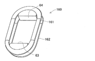
保持器60は、図7および図8(a)に示すように、全体形状としては環状からなる。保持器60は、転動体50の循環路を形成する一対の循環路形成部材61、62と、一対の連結部63、64とから構成される。一対の循環路形成部材61、62は、保持器60の周縁に位置し、長円形をなしている。この一対の循環路形成部材61、62は、一対の中間部材40a、40bを囲む形状をなしている。
As shown in FIGS. 7 and 8A, the
具体的には、循環路形成部材61は、対向する直線部61a、61bと、直線部61a、61bを連結する半円弧状の湾曲部61c、61dとから構成される。また、もう一つの循環路形成部材62は、上記循環路形成部材61と同様に、直線部と湾曲部とから構成される。
Specifically, the circulation
さらに、一対の循環路形成部材61、62は、それぞれ、転動体50の小径軸部52が挿入可能で、且つ、円柱状部51に係合するようなコの字形断面形状に形成されている。つまり、一対の循環路形成部材61、62の幅(内周縁と外周縁との距離)は、転動体50の円柱状部51の最大径よりも小さく形成されている。そして、それぞれの循環路形成部材61、62のコの字形の開口側が、転動体50の円柱状部51の軸方向長さより長い距離だけ離間した状態で、対向するように設けられている。一対の循環路形成部材61、62の対向方向の最大幅は、軌道溝11の側面の幅より僅かに小さく設定されている。つまり、保持器60が、軌道溝11の溝底面および係止突起12により軌道溝11に対して傾きを規制されるように、且つ、軌道溝11に挿入可能となるようにされている。
Furthermore, each of the pair of circulation
一対の連結部63、64は、一対の循環路形成部材61、62の湾曲部61c、61dのうち周方向中央部分(図8(a)の上下端部分)をそれぞれ連結する。つまり、一対の循環路形成部材61、62の間は、図8(c)に示すように、連結部63、64以外の部位において開口している。
A pair of
この連結部63、64は、保持器60の外側に開口するコの字形形状に形成されている。連結部63、64のコの字形形状の底面反開口側(保持器60の内側)は、平面状に形成されている。そして、一対の連結部63、64のコの字形形状の底面反開口側同士が、平行に且つ対向するように設けられている。さらに、この一対の連結部63、64のコの字形形状の底面反開口側の離間距離は、各中間部材40a、40bの軸方向端面44、45間の距離とほぼ一致している。また、連結部63、64のコの字形形状の底面開口側(保持器60の外側)は、底面反開口側に平行な平面状に形成されている。
The connecting
また、連結部63、64のコの字形の開口側の端部の一方が、循環路形成部材61の湾曲部61c、61dのそれぞれの周方向中央部分に連結され、端部の他方が、循環路形成部材62の湾曲部のそれぞれの周方向中央部分に連結される。
In addition, one of the end portions of the
そして、一対の循環路形成部材61、62のコの字形内部に、転動体50の小径軸部52が挿入される。このようにして、転動体50が一対の循環路形成部材61、62に支持されている。つまり、一対の循環路形成部材61、62は、複数の転動体50が一対の中間部材40a、40bの外周を循環可能となるように、転動体50を支持している。ここで、一対の循環路形成部材61、62のコの字形形状は、転動体50の小径軸部52の外周面に対して、僅かに隙間を有する形状をなしている。さらに、転動体50の小径軸部52が循環路形成部材61、62に挿入された状態において、転動体50の円柱状部51は、循環路形成部材61、62の内周縁から内側に突出し、且つ、循環路形成部材61、62の外周縁から外側に突出している。
Then, the small-
ここで、一対の中間部材40a、40bがトリポード軸部22の外周側に配置し、一対の中間部材40a、40bが保持器60の内側に配置された状態において、それぞれの循環路形成部材61、62の直線部61a、61b(図8(a)の左右直線部)(本発明の「第一の循環路」に相当する)は、中間部材40a、40bの動力伝達面42と軌道溝11の側面との間に、両者にほぼ平行な状態(倣う状態)となるように配置される。つまり、この直線部61a、61bにより形成される循環路は、転動体50が動力伝達面42を移動するときの循環路となる。さらに、直線部61a、61bと、動力伝達面42および軌道溝11の側面との間のうち少なくとも一方には隙間が形成されている。
Here, in a state where the pair of
さらに、一対の循環路形成部材61、62の湾曲部61c、61dの両端部分(本発明の「第二の循環路」に相当する)は、中間部材40a、40bの中間部材導入面43に倣うように配置される。つまり、この湾曲部61c、61dの両端部分により形成される循環路は、転動体50が中間部材導入面43を移動するときの循環路である。この循環路は、直線部61a、61bにより形成される循環路に対して滑らかに連続するように接続されている。さらに、当該循環路を形成する湾曲部61c、61dの両端部分と、中間部材導入面43との間に隙間が形成されている。なお、当該循環路を形成する湾曲部61c、61dの両端部分と軌道溝11の側面との間には、当然に隙間が形成されている。
Further, both end portions (corresponding to the “second circulation path” of the present invention) of the
このように、一対の中間部材40a、40bのうち動力伝達方向の一方面をなす動力伝達面42および中間部材導入面43は、保持器60の循環路形成部材61、62との間に隙間を形成し得る形状とされている。つまり、一対の中間部材40a、40bは、一対の循環路形成部材61、62に対して、動力伝達方向に規制されていない。
As described above, the
また、一対の循環路形成部材61、62の湾曲部61c、61dのうち、中間部材導入面43に倣う部分に接続する循環路(本発明における「第三の循環路」に相当する)は、中間部材導入面43に倣う循環路に滑らかに連続して接続されている。
In addition, a circulation path (corresponding to a “third circulation path” in the present invention) connected to a portion following the intermediate
そして、各中間部材40a、40bの軸方向端面44、45の形状および離間距離と、連結部63、64のコの字形形状の底面反開口側の形状および離間距離との関係により、連結部63、64は中間部材40a、40bの外輪10の軸方向(図8(a)の上下方向)への相対動作を規制するように、連結部63、64の間に中間部材40a、40bが設けられる。ただし、中間部材40a、40bは保持器60に対して外輪10の径方向(図8(b)の上下方向)へ規制していないので、中間部材40a、40bは保持器60に対して外輪10の径方向(図8(b)の上下方向)に移動可能である。つまり、保持器60は、一対の中間部材40および軌道溝11の側面に対して、動力伝達方向において接触しない。
And the
上述した等速ジョイント1の動作について説明する。一端側がディファレンシャルギヤに連結された外輪10が動力を受けて回転すると、軌道溝11に嵌合しているそれぞれのローラユニット30を介して、それぞれのトリポード軸部22が動力を伝達し、トリポード20を連結している中間シャフトが等速回転する。この時、ジョイント角が0degでない場合には、トリポード20は外輪10の回転軸直交断面に対してジョイント角分だけ傾いた状態で中間シャフトを中心に回転する。従って、軌道溝11の側面から見た場合に、トリポード軸部22は、外輪10およびトリポード20の回転に伴い、軌道溝11の延伸方向に往復運動し、且つ、軌道溝11に対して揺動する。
The operation of the constant velocity joint 1 described above will be described. When the
また、前述したようにトリポード20は、外輪10の回転軸直交断面に対してジョイント角分だけ傾いているので、外輪10の回転軸方向から見た場合のトリポード軸部22同士がなす角度は、中間シャフトの位相によって変化する。そのため、3本のトリポード軸部22が軌道溝11にそれぞれ収まるためにトリポード20を連結するシャフトの回転軸は、外輪10の回転軸に対して相対的に偏心回転する。従って、トリポード軸部22の端部は、外輪10およびトリポード20の回転に伴い、外輪10の径方向に往復運動する。
Further, as described above, the
ここで、ローラユニット30を構成する一対の中間部材40a、40bのトリポード接触面41がトリポード軸部22に対して揺動可能に嵌合されている。また、ローラユニット30を構成する保持器60により、一対の中間部材40a、40bは、外輪10の軸方向に規制されている。さらに、保持器60は、軌道溝11に嵌合されている。従って、保持器60は、軌道溝11に対して軌道溝11の延伸方向には移動可能であるが、軌道溝11に対する傾きはほぼ一定となる。そして、一対の中間部材40a、40bの外周を転動体50が循環している。
Here, the tripod contact surfaces 41 of the pair of
従って、転動体50は、中間部材40a、40bのうち動力伝達側の部材の動力伝達面42と軌道溝11の側面との間にて、軌道溝11および動力伝達面42に対して軌道溝11の延伸方向への滑りを生じることなく転動する。これにより、誘起スラスト力の発生を抑制できる。
Accordingly, the rolling
また、一対の中間部材40a、40bのうち複数の転動体50を介して動力を受けた部材は、トリポード接触面41で当接するトリポード軸部22に動力伝達する。この時、前述したようにジョイント角が付加されていると、トリポード軸部22が外輪10の径方向に往復運動する。そのため、トリポード軸部22と球面嵌合する中間部材40aは、トリポード軸部22に追従するので、転動体50に対して外輪10の径方向に摺動する。これにより、動力伝達面42における最も動力の加わる荷重点が、転動体50の軸方向に往復運動する。荷重点の移動により、転動体50と軌道溝11の側面が当接する点を支点として、一対の中間部材40a、40bのうち動力伝達側の部材に揺動する力が加わる。
In addition, a member that receives power through the plurality of rolling
しかし、一対の中間部材40a、40bは、動力伝達側とその背面側でそれぞれ独立している。これにより、動力伝達側で発生するトリポード軸部による荷重位置が変化したとしても、一対の中間部材40a、40bのうち動力伝達側の部材の動作が、その背面側の中間部材の動作へ影響を及ぼすことがない。従って、ローラユニット30の背面側が軌道溝11に大きな力を付与することを防止できるので、誘起スラスト力の発生を大幅に低減することができる。また、背面側の中間部材40a(または40b)と軌道溝11との隙間を大きくする必要がなくなり回転ガタの発生を防ぐことができる。
However, the pair of
特に、保持器60は、一対の中間部材40に対して動力伝達方向に規制されていない。これにより、保持器60が、動力伝達の背面側において、転動体50が外輪10の軌道溝11へ力を付与するように作用することを防止できる。従って、このことによっても、動力伝達の背面側における誘起スラスト力の発生を低減できる。
In particular, the
また、一対の中間部材40a、40bには、循環する転動体50を動力伝達面42へ円滑に接触案内するように、動力伝達面42に対して滑らかな中間部材導入面43を形成している。このように、中間部材40a、40bの動力伝達面42と、その動力伝達面42へ転動体50を進入する中間部材導入面43とを同一部材に形成することで、動力伝達面42へ進入する転動体50の姿勢を安定して整えることができる。
The pair of
さらに、一対の循環路形成部材61、62の湾曲部61c、61dの両端部により形成される循環路は、中間部材導入面43に倣う形状からなる。そして、中間部材導入面43に倣う当該循環路のうち動力伝達面42と反対側に接続される循環路(連結部63、64に連結されている循環路)は、中間部材導入面43に倣う循環路に滑らかに連続的に接続されている。
Furthermore, the circulation path formed by both ends of the
ここで、中間部材導入面43は、軌道溝11との間で動力を伝達する部位ではないため、中間部材導入面43を移動する転動体50にそれほど大きな荷重が付加されていない。そのため、連結部63、64が連結されている循環路中間部材導入面43に倣う循環路へ転動体50を安定して進入させることが可能となる。結果として、連結部63、64が連結されている循環路から中間部材導入面43に倣う循環路へ、さらに、中間部材導入面43に倣う循環路から動力伝達面42に倣う循環路へ、転動体50を滑らかに移動させることができる。
Here, since the intermediate
また、トリポード軸部22と一対の中間部材40a、40bを揺動可能な球面嵌合の構成とすることにより、中間部材40a、40bの単位面積当たりの荷重(面圧)が低減され、中間部材40a、40bの耐久性を向上させることができる。また、中間部材40a、40bは、摺動するトリポード軸部22に従動するので、トリポード軸部22に対して位置が定まり安定的に動力伝達することができる。さらに、一対の中間部材40a、40bはトリポード軸部22を挟むように配置されるので、各中間部材40a、40bのトリポード接触面41を全て球面凹状に容易に形成することができる。従って、トリポード軸部22と一対の中間部材40a、40bとの動力伝達面積を増加することができ、また、トリポード軸部22と中間部材40a、40bがアンギュラコンタクトする場合にはアンギュラコンタクトする2箇所の点を更に離間し安定化を図ることができる。
Further, by adopting a spherical fitting configuration in which the
また、転動体50は円柱状のニードルとしているため、当該ニードルが外輪10の軌道溝11の側面に対し円柱軸方向に亘り当接して動力伝達するので、ローラユニット30は全体として回転ガタが小さく、安定した動力伝達ができる。
Further, since the rolling
<第一実施形態の変形態様>
上述した第一実施形態において、一対の中間部材40a、40bのトリポード接触面41は、球面凹状であるとした。この他に、一対の中間部材40a、40bのトリポード接触面41は、円筒面とすることもできる。
<Modification of First Embodiment>
In the first embodiment described above, the tripod contact surfaces 41 of the pair of
この場合、他の構成は第一実施形態と同一である。すなわち、一対の中間部材40a、40bは、そのトリポード接触面41を円筒面となるように形成され、トリポード軸部22を挟むように配置することで、トリポード軸部22と一対の中間部材40は摺動可能となる。
In this case, other configurations are the same as those in the first embodiment. That is, the pair of
このような構成とすることで、トリポード軸部22は、ローラユニット30に対して摺動可能な範囲を大きくすることができ、ジョイント角を付加してトリポード軸部22の摺動する量が大きくなっても、上述した効果を保持したまま動力を伝達することができる。また、上記構成により、転動体50と中間部材40a、40bとの間で摺動することを抑制可能な構成を採用できる。
By adopting such a configuration, the
<第二実施形態>
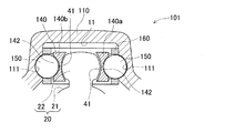
第二実施形態の等速ジョイント101について、図9〜図14を参照して説明する。図9は、第二実施形態の等速ジョイント101の一部の径方向断面図である。図10は、ローラユニット130の斜視図である。図11は、保持器160の斜視図である。図12(a)は、保持器160の平面図であり、図12(b)は、保持器160のJ方向矢視図であり、図12(c)は、保持器160のK−K断面図(長径側の部分断面を含む図)である。図13は、一対の中間部材140の一つの斜視図である。図14(a)は、中間部材140の正面図であり、図14(b)は、中間部材140のL−L部分断面図であり、図14(c)は、中間部材140のM方向矢視図であり、図14(d)は、中間部材140のN−N断面図である。
<Second embodiment>
The constant velocity joint 101 of 2nd embodiment is demonstrated with reference to FIGS. FIG. 9 is a radial cross-sectional view of a part of the constant velocity joint 101 of the second embodiment. FIG. 10 is a perspective view of the
図9および図10に示すように、等速ジョイント101は、外輪110と、トリポード20と、ローラユニット130とから構成される。ここで、第二実施形態の等速ジョイント101は、主に、第一実施形態の等速ジョイント1の転動体50を、ニードルから球体に変更した点が相違する。これに伴い、外輪110の軌道溝111の側面形状、および、一対の中間部材140の外面の形状が、第一実施形態の等速ジョイント1と異なる。なお、トリポード20は、第一実施形態のトリポード20と同一であるため、詳細な説明を省略する。以下相違点のみについて説明する。
As shown in FIGS. 9 and 10, the constant velocity joint 101 includes an
外輪110は、第一実施形態の外輪10に対して、軌道溝111の側面形状のみ相違する。軌道溝111の両側の側面には、図9に示すように、球体からなる転動体150が外輪110の径方向に対して位置決めされるように、転動体150の球面に倣う凹状溝が形成されている。つまり、軌道溝111の側面の凹状溝には、外輪110の径方向断面形状が円弧状とされている。
The
ローラユニット130は、図10に示すように、全体形状としては環状からなり、トリポード軸部22の外周側に配置されている。このローラユニット130は、中間部材140と、複数の転動体150と、保持器160とから構成される。
As shown in FIG. 10, the
中間部材140は、一対の部材140a、140bからなる。一対の中間部材140a、140bの表面は、図13および図14に示すように、トリポード接触面41と、動力伝達面142と、中間部材導入面143と、軸方向端面44、45を有している。トリポード接触面41および軸方向端面44、45は、第一実施形態と同一である。
The
動力伝達面142には、球体である転動体150の球面に倣うように凹状溝が形成されている。また、この動力伝達面142に隣り合う両側に形成されている中間部材導入面43にも、動力伝達面142と同様の凹状溝が形成されている。動力伝達面142および中間部材導入面143の他の構成については、第一実施形態と同一である。
A concave groove is formed in the
転動体150は、図10に示すように、球体であり、ニードルの場合と同様に中間部材140の外周を循環するように複数配置される。
As shown in FIG. 10, the rolling
保持器160は、転動体がニードルの場合と同様に全体形状としては環状からなる。第一実施形態の保持器60を構成する循環路形成部材61、62がコの字形形状をなしていたのに対して、第二実施形態の保持器160の循環路形成部材161、162は、図9の上下方向で対向するように配置され、且つ、球状の転動体150を支持するように円弧凹状溝が形成されている。
The
上述した等速ジョイント101の動作について説明する。転動体150がニードルの場合と異なり、各中間部材140a、140bの円弧凹状溝と転動体150の球面とが当接することで、外輪110の軸方向から見た場合に、両者は揺動可能となる。従って、ジョイント角をとったときに、外輪110の軸方向から見た場合に、トリポード軸方向に摺動するトリポード軸部22に対して中間部材140a、140bが揺動する。
The operation of the constant velocity joint 101 described above will be described. Unlike the case where the rolling
このように構成される第二実施形態の等速ジョイント101は、第一実施形態の等速ジョイント1による効果と同様の効果を奏する。さらに、球体である転動体150は高剛性で、且つ、循環性に優れる。さらに、加工工程の少ない球体は比較的生産しやすく、等速ジョイント101の組付けにおいても簡素化できる。さらに、転動体150を球体とすることで、トリポード軸部22と軌道溝111の変動する位置関係に応じて各部材にかかる荷重点が偏ることなく、動力を伝達することができる。
The constant velocity joint 101 of 2nd embodiment comprised in this way has an effect similar to the effect by the constant velocity joint 1 of 1st embodiment. Furthermore, the rolling
<第三実施形態>
第三実施形態の等速ジョイント201について、図15を参照して説明する。図15は、第三実施形態の等速ジョイント201の一部の径方向断面図である。図15に示すように、等速ジョイント201は、外輪110と、トリポード20と、ローラユニット230とから構成される。ここで、第三実施形態の等速ジョイント201は、第二実施形態の等速ジョイント101の転動体150を、球体からバレル状コロに変更した点が相違する。以下相違点のみについて説明する。
<Third embodiment>
The constant velocity joint 201 of the third embodiment will be described with reference to FIG. FIG. 15 is a radial cross-sectional view of a part of the constant velocity joint 201 of the third embodiment. As shown in FIG. 15, the constant velocity joint 201 includes an
つまり、ローラユニット230は、中間部材140と、複数の転動体250と、保持器160とから構成される。転動体250は、バレル状コロであり、球体およびニードルの場合と同様に中間部材140の外周を循環するように複数配置される。バレル状コロとは、柱状であり、柱延伸直交方向に切断した断面が円形からなり、柱延伸方向に切断した断面における外周面に相当する部分が円弧凸状なす転動体である。
That is, the
このような構成にすることで、第二実施形態における球体の転動体150と同様に、動力伝達時の各部材にかかる荷重点の偏りを防止しながら、柱延伸直交方向の幅を球体に比して小さくすることができ、結果として、等速ジョイント201全体の小型化を図ることができる。
By adopting such a configuration, as in the
<第四実施形態>
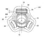
第四実施形態の等速ジョイント301について、図16を参照して説明する。第四実施形態の等速ジョイント301は、第一実施形態の等速ジョイント1の構成を基本とした場合において、外輪PCR(ピッチ円半径)302とトリポードPCR303とを異なるように設定したものである。図16は、第四実施形態の等速ジョイント301の一部の径方向断面図である。なお、第四実施形態の等速ジョイント301は、実質的に、第一実施形態の等速ジョイント1と同一構成からなるため、各構成部品には同一符号を用いる。
<Fourth embodiment>
The constant velocity joint 301 of 4th embodiment is demonstrated with reference to FIG. The constant velocity joint 301 of the fourth embodiment is configured such that the outer ring PCR (pitch circle radius) 302 and the
図16に示すように、トリポード軸部22の外周面は球面凸状であり、外輪回転軸13と中間シャフト回転軸23が一致している姿勢において、トリポードPCR303を外輪PCR302より大きく設定している。
As shown in FIG. 16, the outer peripheral surface of the
外輪PCR302は、動力伝達面42と軌道溝11の側面との間に位置する転動体50において、その転動体50のトリポード軸方向(図16の上下方向)の幅中心を通りトリポード軸と直交する平面におけるトリポード軸上の交点304と、外輪回転軸12との最短距離をいう。トリポードPCR303は、トリポード軸部22の外周面の曲率中心305と、中間シャフト回転軸23との最短距離をいう。
The outer ring PCR302 is perpendicular to the tripod axis in the rolling
ここで、図17および図18を参照して説明する。図17は、所定ジョイント角を付加した等速ジョイント301における、外輪10の開口側から見た図である。図18は、所定ジョイント角を付加した等速ジョイント301における、外輪10の開口側から見た図である。図19は、オフセット量別における、ジョイント角と荷重点との最大最小移動量を示すグラフである。図19において、(a)はオフセット量0mmであり、(b)はオフセット量0.1mmであり、(c)はオフセット量0.2mmであり、(d)はオフセット量0.3mmである。当該荷重点とは、トリポード軸部22と中間部材40a、40bとの間において、動力伝達の際に荷重が加わる位置の外輪径方向位置である。
Here, it demonstrates with reference to FIG. 17 and FIG. FIG. 17 is a view of the constant velocity joint 301 with a predetermined joint angle as viewed from the opening side of the
図17および図18に示すように、ジョイント角を付加した時に、回転位相によって荷重点が移動する。ここで、ジョイント角が0degの場合における、荷重点を基準荷重点306とする。
As shown in FIGS. 17 and 18, when a joint angle is added, the load point moves according to the rotational phase. Here, the load point when the joint angle is 0 deg is defined as a
例えば、図17では、中間シャフト回転軸23は図17の右方向にジョイント角として付加され、この状態で中間シャフトと共にトリポード20が回転し、トリポード軸部22の一つが図17の上方向に位置している。すると、上述したように、トリポード20は外輪10と相対して偏心回転する。この偏心回転に起因して、第一の荷重点307は、基準荷重点306より外輪10の径方向外方に移動し、且つ、外輪回転軸12から最も離間した位置となる。
For example, in FIG. 17, the intermediate
一方、図18では、中間シャフト回転軸23は図18の上方向にジョイント角として付加され、この状態で中間シャフトと共にトリポード20が回転し、トリポード軸部22の一つが図18の上方向に位置している。すると、トリポード20の偏心回転に起因して、第二の荷重点308は、基準荷重点306より外輪10の径方向内方に移動し、外輪回転軸12に最も接近した位置となる。
On the other hand, in FIG. 18, the intermediate
第一の荷重点307が基準荷重点306からの移動量は、第二の荷重点308が基準荷重点306からの移動量より小さい。従って、仮に外輪PCR302とトリポードPCR303とを一致するように設定すると、トリポード軸部22がローラユニット30に加える荷重点の移動量平均は、外輪回転軸12に近接する方向に偏ることになる。従って、転動体50の偏磨耗の増大の原因となる。
The amount of movement of the
そこで、予めトリポードPCR303を外輪PCR302よりも大きく設定(オフセット)することにより、上記荷重点の移動量平均がローラユニット30の厚み中央になるようにし、荷重の偏りを防止することができる。ただし、第一の荷重点307および第二の荷重点308のそれぞれの基準荷重点306からの移動量は、付加されるジョイント角に依存するので、所定のジョイント角によって最適なオフセット量が異なる。図19に示すように、それぞれのオフセット量におけるジョイント角で、移動した荷重点の最大値と最小値を見ると、例えば、ジョイント角7degならオフセット量0.1mmが最適であり、同様に、ジョイント角10degならオフセット量0.2mm、ジョイント角13degならオフセット量0.3mmがそれぞれ最適であることが求められる。
Therefore, by setting (offset) the
従って、その等速ジョイントを使用する際に、想定する常用のジョイント角に応じて、オフセット量を設定することで、転動体50の偏磨耗の増大を防ぎ、結果として、等速ジョイントの耐久性を向上しまた、振動や騒音を低減することができる。
Therefore, when the constant velocity joint is used, the offset amount is set according to the assumed common joint angle, thereby preventing the uneven wear of the rolling
<第五実施形態>
第五実施形態の等速ジョイント401について、図20および図21を参照して説明する。図20は、第五実施形態の等速ジョイント401の一部の径方向断面図である。図21は、オフセット量別のジョイント角と回転ガタ量を示すグラフである。図21において、(a)はオフセット量0mmであり、(b)はオフセット量0.2mmであり、(c)はオフセット量0.3mmであり、(d)はオフセット量0.6mmである。
<Fifth embodiment>
A constant velocity joint 401 according to the fifth embodiment will be described with reference to FIGS. FIG. 20 is a radial cross-sectional view of a part of the constant velocity joint 401 of the fifth embodiment. FIG. 21 is a graph showing the joint angle and the rotational play amount for each offset amount. In FIG. 21, (a) is an offset amount of 0 mm, (b) is an offset amount of 0.2 mm, (c) is an offset amount of 0.3 mm, and (d) is an offset amount of 0.6 mm.
転動体50は球体であり、この場合においても、第四実施形態で述べたようにトリポード20の偏心回転に起因して、外輪PCR302とトリポードPCR303とを一致するように設定した場合には、荷重点の移動量平均が外輪回転軸13に近接する方向に偏り、この偏りが発生しないジョイント角が0degの時に回転ガタが最小となり、ジョイント角が付加されるに従って回転ガタが増大するという問題がある。
The rolling
そこで、図20に示すように、予めトリポードPCR303を外輪PCR302よりも大きく設定(オフセット)することで、所定のジョイント角を付加した時に回転ガタが最小になるようにし、回転ガタの増大を防ぐことができる。ただし、回転ガタの量は、付加されるジョイント角に依存するので、所定のジョイント角によって最適なオフセット量が異なる。図21に示すように、それぞれのオフセット量におけるジョイント角で、回転ガタの増分を見ると、例えば、ジョイント角6degならオフセット量0.2mmが最適であり、同様に、ジョイント角7degならオフセット量0.3mm、ジョイント角10degならオフセット量0.6mmがそれぞれ最適であることが求められる。
Therefore, as shown in FIG. 20, the
従って、その等速ジョイントを使用する際に、想定する常用のジョイント角に応じて、オフセット量を設定することで、転動体50の回転ガタの増大を防ぎ、結果として、等速ジョイントの耐久性を向上しまた、振動や騒音を低減することができる。なお、転動体50がバレル状コロの場合にも、上記のようにトリポードPCR303を設定することで、同様の効果を得ることができる。
Therefore, when the constant velocity joint is used, an offset amount is set according to the assumed common joint angle, thereby preventing an increase in the rotational play of the rolling
1、101、201、301、401:等速ジョイント
10、110:外輪、 11、111:軌道溝、 12:係止突起
13:外輪回転軸
20:トリポード、 21:ボス部、 21a:内周スプライン
22:トリポード軸部、 23:中間シャフト回転軸
30、130:ローラユニット
40、140:中間部材、 40a、40b、140a、140b:各中間部材
41:トリポード接触面、 42、142:動力伝達面
43、143:中間部材導入面、 44、45:軸方向端面
50、150、250:転動体、 51:円柱状部、 52:小径軸部
60、160:保持器
61、62、161、162:循環路形成部材
61a、61b:直線部、 61c、61d:湾曲部、 63、64:連結部
302:外輪PCR、 303:トリポードPCR、 304:交点
305:曲率中心、 306:基準荷重点
307:第一の荷重点、 308:第二の荷重点
DESCRIPTION OF
Claims (8)
シャフトに連結されるボス部、および、前記ボス部の外周面からそれぞれ前記ボス部の径方向外方に延びるように立設されそれぞれの前記軌道溝に挿入される3本のトリポード軸部を備えるトリポードと、
前記軌道溝の側面の両側から前記トリポード軸部を挟むように配置され、且つ、前記トリポード軸部に対して揺動可能に設けられる一対の中間部材と、
前記軌道溝の側面と前記一対の中間部材の前記軌道溝の側面に対向する動力伝達面との間に、前記軌道溝の側面に沿って転動可能に設けられる複数の転動体と、
前記転動体が前記一対の中間部材の外周を循環可能となるように前記転動体を支持する保持器と、
を備えることを特徴とする摺動式トリポード型等速ジョイント。 An outer ring having a cylindrical shape and formed with three raceway grooves extending in the outer ring rotation axis direction on the inner peripheral surface;
A boss portion coupled to the shaft, and three tripod shaft portions that are erected so as to extend radially outward of the boss portion from the outer peripheral surface of the boss portion and are inserted into the raceway grooves, respectively. Tripod,
A pair of intermediate members disposed so as to sandwich the tripod shaft from both sides of the side surface of the raceway groove, and provided so as to be swingable with respect to the tripod shaft;
A plurality of rolling elements provided between the side surface of the raceway groove and a power transmission surface facing the side surface of the raceway groove of the pair of intermediate members so as to roll along the side surface of the raceway groove;
A cage that supports the rolling elements such that the rolling elements can circulate around the outer periphery of the pair of intermediate members;
A sliding tripod constant velocity joint characterized by comprising:
前記外輪回転軸と前記シャフト回転軸が一致している姿勢において、
前記転動体のトリポード軸方向の幅中心を通りトリポード軸と直交する平面におけるトリポード軸上の点と、前記外輪回転軸との距離を外輪PCRとし、
前記トリポード軸部の外周面の曲率中心と、前記シャフト回転軸との距離をトリポードPCRとし、
前記トリポードPCRは、前記外輪PCRより大きく設定されることを特徴とする請求項1に記載の摺動式トリポード型等速ジョイント。 The outer peripheral surface of the tripod shaft portion is a spherical convex shape,
In a posture in which the outer ring rotation axis and the shaft rotation axis coincide with each other,
A distance between a point on the tripod axis in a plane passing through the center of the tripod axis direction of the rolling element and orthogonal to the tripod axis and the outer ring rotation axis is defined as an outer ring PCR;
The distance between the center of curvature of the outer peripheral surface of the tripod shaft and the shaft rotation axis is defined as tripod PCR,
The sliding tripod constant velocity joint according to claim 1, wherein the tripod PCR is set to be larger than the outer ring PCR.
前記動力伝達面を移動する前記転動体の循環路であって前記動力伝達面に倣う第一の循環路と、
前記中間部材導入面を移動する前記転動体の循環路であって前記中間部材導入面に倣い且つ前記第一の循環路に滑らかに接続する第二の循環路と、
前記第二の循環路のうち前記第一の循環路と反対側端部に滑らかに接続する第三の循環路と、
を有することを特徴とする請求項3に記載の摺動式トリポード型等速ジョイント。 The circulation path which is the locus of the rolling elements circulated by the cage is
A first circulation path that is a circulation path of the rolling element that moves on the power transmission surface and follows the power transmission surface;
A second circulation path that is a circulation path of the rolling element that moves on the intermediate member introduction surface and that follows the intermediate member introduction surface and is smoothly connected to the first circulation path;
A third circulation path smoothly connected to the end opposite to the first circulation path of the second circulation path;
The sliding tripod type constant velocity joint according to claim 3, wherein:
前記一対の中間部材の内面は、前記トリポード軸部の外周面に嵌合される球面凹状であることを特徴とする請求項1〜5のいずれか一項に記載の摺動式トリポード型等速ジョイント。 The outer peripheral surface of the tripod shaft portion is a spherical convex shape,
6. The sliding tripod constant velocity according to claim 1, wherein inner surfaces of the pair of intermediate members have a spherical concave shape fitted to an outer peripheral surface of the tripod shaft portion. Joint.
前記外輪回転軸と前記シャフト回転軸が一致している姿勢において、
前記保持器は、前記ニードルの円柱軸方向が前記トリポード軸方向と平行となるように前記ニードルを支持し、
前記一対の中間部材は、前記ニードルに対し前記外輪径方向に摺動可能な前記動力伝達面を形成することを特徴とする請求項1〜6のいずれか一項に記載の摺動式トリポード型等速ジョイント。 The rolling element is a cylindrical needle,
In a posture in which the outer ring rotation axis and the shaft rotation axis coincide with each other,
The retainer supports the needle such that the cylindrical axis direction of the needle is parallel to the tripod axis direction,
The sliding tripod type according to any one of claims 1 to 6, wherein the pair of intermediate members form the power transmission surface that is slidable in the outer ring radial direction with respect to the needle. Constant velocity joint.
前記外輪回転軸と前記シャフト回転軸が一致している姿勢において、
前記一対の中間部材は、前記転動体に対し前記外輪径方向に揺動可能な前記動力伝達面を形成することを特徴とする請求項1〜6のいずれか一項に記載の摺動式トリポード型等速ジョイント。 The rolling element is a spherical or barrel-shaped roller,
In a posture in which the outer ring rotation axis and the shaft rotation axis coincide with each other,
The sliding tripod according to any one of claims 1 to 6, wherein the pair of intermediate members form the power transmission surface that can swing in the outer ring radial direction with respect to the rolling elements. Type constant velocity joint.
Priority Applications (15)
| Application Number | Priority Date | Filing Date | Title |
|---|---|---|---|
| JP2008164967A JP5240506B2 (en) | 2008-06-24 | 2008-06-24 | Sliding tripod type constant velocity joint |
| CN201310263095.1A CN103352926B (en) | 2008-06-24 | 2009-06-23 | Sliding type tripod constant velocity joint |
| CN200980132142.0A CN102124243B (en) | 2008-06-24 | 2009-06-23 | Sliding type tripod constant velocity joint |
| PCT/JP2009/061411 WO2009157448A1 (en) | 2008-06-24 | 2009-06-23 | Sliding type tripod constant velocity joint |
| US12/737,243 US8540581B2 (en) | 2008-06-24 | 2009-06-23 | Sliding type tripod constant velocity joint |
| CN201310263957.0A CN103352927B (en) | 2008-06-24 | 2009-06-23 | sliding type tripod constant velocity joint |
| EP13002280.9A EP2623809B1 (en) | 2008-06-24 | 2009-06-23 | Sliding type tripod constant velocity joint |
| EP09770158.5A EP2299135B1 (en) | 2008-06-24 | 2009-06-23 | Sliding type tripod constant velocity joint |
| CN201310263091.3A CN103352925B (en) | 2008-06-24 | 2009-06-23 | sliding type tripod constant velocity joint |
| EP13002278.3A EP2623807B1 (en) | 2008-06-24 | 2009-06-23 | Sliding type tripod constant velocity joint |
| EP13002279.1A EP2623808B1 (en) | 2008-06-24 | 2009-06-23 | Sliding type tripod constant velocity joint |
| US13/495,997 US8454448B2 (en) | 2008-06-24 | 2012-06-13 | Sliding type tripod constant velocity joint |
| US13/523,181 US8550924B2 (en) | 2008-06-24 | 2012-06-14 | Sliding type tripod constant velocity joint |
| US13/523,202 US8376867B2 (en) | 2008-06-24 | 2012-06-14 | Sliding type tripod constant velocity joint |
| US13/937,034 US8727895B2 (en) | 2008-06-24 | 2013-07-08 | Sliding type tripod constant velocity joint |
Applications Claiming Priority (1)
| Application Number | Priority Date | Filing Date | Title |
|---|---|---|---|
| JP2008164967A JP5240506B2 (en) | 2008-06-24 | 2008-06-24 | Sliding tripod type constant velocity joint |
Publications (2)
| Publication Number | Publication Date |
|---|---|
| JP2010007701A true JP2010007701A (en) | 2010-01-14 |
| JP5240506B2 JP5240506B2 (en) | 2013-07-17 |
Family
ID=41588450
Family Applications (1)
| Application Number | Title | Priority Date | Filing Date |
|---|---|---|---|
| JP2008164967A Expired - Fee Related JP5240506B2 (en) | 2008-06-24 | 2008-06-24 | Sliding tripod type constant velocity joint |
Country Status (1)
| Country | Link |
|---|---|
| JP (1) | JP5240506B2 (en) |
Cited By (4)
| Publication number | Priority date | Publication date | Assignee | Title |
|---|---|---|---|---|
| JP2011163443A (en) * | 2010-02-09 | 2011-08-25 | Jtekt Corp | Sliding tripod type constant velocity joint |
| DE102016110983A1 (en) | 2015-06-18 | 2016-12-22 | Jtekt Corporation | Homokinetic shift joint |
| DE102016110984A1 (en) | 2015-06-18 | 2016-12-22 | Jtekt Corporation | Homokinetic shift joint |
| CN112211914A (en) * | 2020-09-28 | 2021-01-12 | 万向钱潮股份有限公司 | Three-ball pin structure |
Citations (8)
| Publication number | Priority date | Publication date | Assignee | Title |
|---|---|---|---|---|
| JPS5940016A (en) * | 1982-08-31 | 1984-03-05 | Ntn Toyo Bearing Co Ltd | Uniform speed universal joint |
| JPS62255616A (en) * | 1986-03-31 | 1987-11-07 | ゼネラル モ−タ−ズ コ−ポレ−シヨン | Expansion type three-leg type universal joint |
| JPS63163031A (en) * | 1986-12-16 | 1988-07-06 | グレンツアー スピーセル | Transmission coupler |
| JPH03172622A (en) * | 1989-11-03 | 1991-07-26 | Loehr & Bromkamp Gmbh | Tripod type joint |
| JPH07501126A (en) * | 1991-10-15 | 1995-02-02 | ジーケーエヌ オートモウティブ インコーポレイテッド | Roller bearing and cage assembly |
| JP2763624B2 (en) * | 1989-10-31 | 1998-06-11 | エヌティエヌ株式会社 | Constant velocity joint |
| US6174239B1 (en) * | 1997-02-11 | 2001-01-16 | Gkn Automotive Ag | Tripod sliding constant velocity joint |
| JP2002147482A (en) * | 2000-10-16 | 2002-05-22 | Delphi Technologies Inc | Tripod type constant velocity joint |
-
2008
- 2008-06-24 JP JP2008164967A patent/JP5240506B2/en not_active Expired - Fee Related
Patent Citations (8)
| Publication number | Priority date | Publication date | Assignee | Title |
|---|---|---|---|---|
| JPS5940016A (en) * | 1982-08-31 | 1984-03-05 | Ntn Toyo Bearing Co Ltd | Uniform speed universal joint |
| JPS62255616A (en) * | 1986-03-31 | 1987-11-07 | ゼネラル モ−タ−ズ コ−ポレ−シヨン | Expansion type three-leg type universal joint |
| JPS63163031A (en) * | 1986-12-16 | 1988-07-06 | グレンツアー スピーセル | Transmission coupler |
| JP2763624B2 (en) * | 1989-10-31 | 1998-06-11 | エヌティエヌ株式会社 | Constant velocity joint |
| JPH03172622A (en) * | 1989-11-03 | 1991-07-26 | Loehr & Bromkamp Gmbh | Tripod type joint |
| JPH07501126A (en) * | 1991-10-15 | 1995-02-02 | ジーケーエヌ オートモウティブ インコーポレイテッド | Roller bearing and cage assembly |
| US6174239B1 (en) * | 1997-02-11 | 2001-01-16 | Gkn Automotive Ag | Tripod sliding constant velocity joint |
| JP2002147482A (en) * | 2000-10-16 | 2002-05-22 | Delphi Technologies Inc | Tripod type constant velocity joint |
Cited By (4)
| Publication number | Priority date | Publication date | Assignee | Title |
|---|---|---|---|---|
| JP2011163443A (en) * | 2010-02-09 | 2011-08-25 | Jtekt Corp | Sliding tripod type constant velocity joint |
| DE102016110983A1 (en) | 2015-06-18 | 2016-12-22 | Jtekt Corporation | Homokinetic shift joint |
| DE102016110984A1 (en) | 2015-06-18 | 2016-12-22 | Jtekt Corporation | Homokinetic shift joint |
| CN112211914A (en) * | 2020-09-28 | 2021-01-12 | 万向钱潮股份有限公司 | Three-ball pin structure |
Also Published As
| Publication number | Publication date |
|---|---|
| JP5240506B2 (en) | 2013-07-17 |
Similar Documents
| Publication | Publication Date | Title |
|---|---|---|
| JP5376239B2 (en) | Sliding tripod type constant velocity joint | |
| US8727895B2 (en) | Sliding type tripod constant velocity joint | |
| JP5240506B2 (en) | Sliding tripod type constant velocity joint | |
| JP2006112495A (en) | Uniform joint | |
| JP5176717B2 (en) | Sliding tripod type constant velocity joint | |
| JP4952667B2 (en) | Sliding tripod type constant velocity joint | |
| JP5287519B2 (en) | Sliding tripod type constant velocity joint | |
| JP5240507B2 (en) | Sliding tripod type constant velocity joint | |
| JP5083067B2 (en) | Sliding tripod type constant velocity joint | |
| JP5604889B2 (en) | Sliding tripod type constant velocity joint | |
| JP2012197803A (en) | Sliding type tripod constant velocity joint | |
| JP5564865B2 (en) | Sliding tripod type constant velocity joint | |
| JP5585032B2 (en) | Sliding tripod type constant velocity joint | |
| JP5293512B2 (en) | Sliding tripod type constant velocity joint | |
| JP2009014179A (en) | Tripod-type constant velocity universal joint | |
| JP5726694B2 (en) | Constant velocity joint | |
| JP5760560B2 (en) | Sliding tripod type constant velocity joint | |
| JP2017008989A (en) | Slide type constant velocity joint | |
| JP2010144898A (en) | Sliding tripod constant-velocity joint and roller unit | |
| JP2005233233A (en) | Shaft coupling | |
| JP2006266328A (en) | Constant velocity universal joint | |
| JP2006090515A (en) | Constant velocity universal joint | |
| JP2006090512A (en) | Constant velocity universal joint | |
| JP2006097853A (en) | Constant velocity universal joint and its manufacturing method | |
| JP2006266322A (en) | Constant velocity universal joint |
Legal Events
| Date | Code | Title | Description |
|---|---|---|---|
| A621 | Written request for application examination |
Free format text: JAPANESE INTERMEDIATE CODE: A621 Effective date: 20110221 |
|
| A521 | Written amendment |
Free format text: JAPANESE INTERMEDIATE CODE: A523 Effective date: 20110808 |
|
| A131 | Notification of reasons for refusal |
Free format text: JAPANESE INTERMEDIATE CODE: A131 Effective date: 20121211 |
|
| A521 | Written amendment |
Free format text: JAPANESE INTERMEDIATE CODE: A523 Effective date: 20130208 |
|
| TRDD | Decision of grant or rejection written | ||
| A01 | Written decision to grant a patent or to grant a registration (utility model) |
Free format text: JAPANESE INTERMEDIATE CODE: A01 Effective date: 20130307 |
|
| A61 | First payment of annual fees (during grant procedure) |
Free format text: JAPANESE INTERMEDIATE CODE: A61 Effective date: 20130320 |
|
| FPAY | Renewal fee payment (event date is renewal date of database) |
Free format text: PAYMENT UNTIL: 20160412 Year of fee payment: 3 |
|
| R150 | Certificate of patent or registration of utility model |
Free format text: JAPANESE INTERMEDIATE CODE: R150 |
|
| LAPS | Cancellation because of no payment of annual fees |