JP2010006215A - Vehicular seat control device - Google Patents
Vehicular seat control device Download PDFInfo
- Publication number
- JP2010006215A JP2010006215A JP2008167210A JP2008167210A JP2010006215A JP 2010006215 A JP2010006215 A JP 2010006215A JP 2008167210 A JP2008167210 A JP 2008167210A JP 2008167210 A JP2008167210 A JP 2008167210A JP 2010006215 A JP2010006215 A JP 2010006215A
- Authority
- JP
- Japan
- Prior art keywords
- state
- side support
- vehicle
- vehicle seat
- support portion
- Prior art date
- Legal status (The legal status is an assumption and is not a legal conclusion. Google has not performed a legal analysis and makes no representation as to the accuracy of the status listed.)
- Granted
Links
Images


Landscapes
- Seats For Vehicles (AREA)
Abstract
Description
本発明は、車両に乗車した着座者を支持する車両用シートの制御装置に関する。 The present invention relates to a control device for a vehicle seat that supports a seated occupant in a vehicle.
従来より、車両が旋回する際の運転感覚を向上させるには、乗車用シートの端部を盛り上げた形状(サイドサポート)とし、運転者の上体を車体左右方向に必要以上に変位させないようにすることが望ましいとされている。このようなサイドサポートを制御する技術としては、下記の特許文献1のように、乗降者の体格を検知して乗車しにくいか否かを判断し、サイドサポートの張り出し量を調整するものや、下記の特許文献2のようにエンジンの非作働時にシートの調整を解除するものがある。
しかしながら、上述した特許文献1のようにサイドサポートを自動開閉させる技術では、乗員の乗降時には乗降性向上のためにサイドサポートを開いた状態にし、乗員の乗車時にはサイドサポートを閉じて乗員を支持するようにしている。しかし、サイドサポートによる乗員の支持は、車両が走行していない場合には必要ないにも関わらず、サイドサポートによって乗員を締めた状態となっている。したがって、車両の停車中には、乗員に対してサイドサポートによって締め付けられているという違和感を与えることがあった。
However, in the technology for automatically opening and closing the side support as described in
また、特許文献2に記載された技術によれば、エンジンが非動作である時にはサイドサポートを開いた状態にし、エンジンを動作させている時にはサイドサポートを閉じて乗員を支持するようにしている。したがって、エンジンをアイドルストップ状態とする車両においては、エンジンが非動作状態から動作状態に遷移する時及びその逆の動作時に、毎回自動調整機能が働いてしまい、乗員に対して煩わしい感覚を与える可能性がある。更にこの特許文献2に記載された技術では、毎回の動作時に最適な締め付け位置を調整するので、当該調整動作が乗員に対して煩わしいと感じさせるおそれがあった。
According to the technique described in
そこで、本発明は、上述した実情に鑑みて提案されたものであり、右側支持部及び左側支持部の自動調整動作によって乗員に煩わしさを与えることを回避できる車両用シートの制御装置を提供することを目的とする。 Therefore, the present invention has been proposed in view of the above-described circumstances, and provides a vehicle seat control device that can avoid annoying an occupant by an automatic adjustment operation of a right support portion and a left support portion. For the purpose.
本発明では、着座者が着座する車両用シートに含まれ、車両用シートに着座した着座者の上体を両側面から支持する右側支持部及び左側支持部を駆動する駆動手段と、車両状態を判断する車両状態判断手段と、車両状態判断手段により判断された車両状態に基づいて、駆動手段によって右側支持部及び左側支持部の位置を調整させて着座者を支持する自動調整動作を起動させる制御手段とを有する。このような本発明においては、制御手段によって、車両状態としてイグニッション状態、エンジン状態、シートベルト状態、ドア開閉状態、車両用シートの状態、又はステアリング位置状態の組み合わせに基づいて、自動調整動作を起動させることにより、上述の課題を解決する。 In the present invention, a right-side support part that is included in a vehicle seat on which a seated person is seated and supports the upper body of the seated person seated on the vehicle seat from both sides, a driving means that drives the left-side support part, and a vehicle state Vehicle state determining means for determining and control for starting an automatic adjustment operation for supporting the seated person by adjusting the positions of the right support portion and the left support portion by the driving means based on the vehicle state determined by the vehicle state determining means Means. In the present invention, the automatic adjustment operation is started by the control means based on the combination of the ignition state, the engine state, the seat belt state, the door opening / closing state, the vehicle seat state, or the steering position state as the vehicle state. By doing so, the above-mentioned problems are solved.
本発明によれば、車両状態としてイグニッション状態、エンジン状態、シートベルト状態、ドア開閉状態、車両用シートの状態、又はステアリング位置状態の組み合わせに基づいて、自動調整動作を起動させるので、車両状態に基づく使用場面に応じて自動調整動作を起動させることができ、右側支持部及び左側支持部の自動調整動作によって乗員に煩わしさを与えることを回避できる。 According to the present invention, the automatic adjustment operation is activated based on a combination of the ignition state, the engine state, the seat belt state, the door opening / closing state, the vehicle seat state, or the steering position state as the vehicle state. The automatic adjustment operation can be started in accordance with the use scene based on the situation, and it can be avoided that the occupant is bothered by the automatic adjustment operation of the right support portion and the left support portion.
以下、本発明の実施の形態について図面を参照して説明する。 Hereinafter, embodiments of the present invention will be described with reference to the drawings.
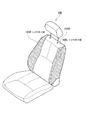
本発明は、例えば図1に示すように構成された車両用シート100を制御する車両用シートの制御装置に適用される。
The present invention is applied to, for example, a vehicle seat control device that controls a
[車両用シートの構成]
この車両用シート100には、運転者の背を支持する背面部100B内部に、図2に示すような構成が備えられている。図1に網掛けで示した背面部100Bの左右に構成されたサイドサポート部100L(左側支持部)、サイドサポート部100R(右側支持部)は、当該車両用シート100に着座した運転者の上体姿勢が乱れた場合に、上体を支えるように可動して運転者の姿勢を安定化させるものである。
[Configuration of vehicle seat]
The
車両用シート100は、図2に示すように、サイドサポート部100L、100Rをそれぞれ構成するサイドサポート可動部110L,110Rと、車両用シート100の背面部100Bの基本骨格であるシートフレーム111と、車両用シート100の背面部100Bにかかる運転者の荷重を検出する歪みゲージ119とを備えている。なお、本例においては、サイドサポート部100L、サイドサポート部100Rの位置を自動調整するための構成として、着座者に対するサイドサポート部100L、サイドサポート部100Rの荷重を検出する歪みゲージ119を備えているが他の構成であっても良い。また、この車両用シート100の運転者の背中と接触する側には、クッション支持スプリング121により支持される図示しないクッション部材が配される。
As shown in FIG. 2, the
シートフレーム111は、上述したように背面部100Bの基本骨格である。このシートフレーム111には、運転者が着座した状態において運転者の左側体側部近辺、右側体側近辺となる位置にサイドサポート可動部110L,110Rが設けられている。また、シートフレーム111には、上述したクッション部材を支持するクッション支持スプリング121、車両用シート100のヘッドレスト100Hを取り付けるためのヘッドレスト取り付け部122が設けられている。
The
サイドサポート部100L,100Rを、それぞれ構成するサイドサポート可動部110L,110Rは、サイドサポート部100L,100Rを可動させるための可動機構を有している。サイドサポート可動部110L,110Rは、全く同一の構成となっているため、サイドサポート可動部110Rについてのみ説明をし、後で、構成部材の対応関係を示すことでサイドサポート可動部110Lについての説明を省略する。
The side support
サイドサポート可動部110Rは、回転支持部112R,113Rと、サイドサポートフレーム114Rと、リンク機構をなすリンク115R、116R、117Rと、右側モータ118Rとを備えている。
The side support
回転支持部112R、113Rは、サイドサポート部100Rの骨格であり、サイドサポート可動部110Rにおける可動の対象であるサイドサポートフレーム114Rを、回転可能としながらシートフレーム111上に支持する。サイドサポートフレーム114Rは、図示しないクッション部材で覆われることで、サイドサポート部100Rを形成することになる。
The rotation support
回転支持部112Rには、シートフレーム111に固定された右側モータ118Rの回転運動をリンク116R、117Rを介してサイドサポートフレーム114Rに伝達するためのリンク115Rが設けられている。これにより、右側モータ118Rが回転駆動されると、リンク117R、116R、115Rを介して、その回転が回転支持部112Rを回転させ、さらに回転支持部112Rで支持されているサイドサポートフレーム114Rを、シートフレーム111に対して平行となる方向へ近付ける矢印A方向、又は垂直となる方向に近付ける矢印B方向へと駆動する。
The
サイドサポート可動部110Lは、上述したようにサイドサポート可動部110Rと全く同一の構成である。各構成部材の対応関係を示すと、サイドサポート可動部110Lの回転支持部112L、113L、サイドサポートフレーム114L、リンク115L、116L、117L、左側モータ118Lは、ぞれぞれ、サイドサポート可動部110Rの回転支持部112R、113R、サイドサポートフレーム114R、リンク115R、116R、117R、右側モータ118Rに対応している。
The side support
したがって、サイドサポート可動部110Lは、左側モータ118Lが回転駆動されると、リンク117L、116L、115Lを介して、その回転が回転支持部112Lを回転させ、さらに回転支持部112Lで支持されているサイドサポートフレーム114Lを、シートフレーム111に対して平行となる方向へ近付ける矢印C方向、又は垂直となる方向に近付ける矢印D方向へと駆動する。
Therefore, when the left motor 118L is driven to rotate, the side support
このように、サイドサポート可動部110L、110Rを構成することで、左側モータ118L、右側モータ118Rの回転角を、左右のサイドサポートフレーム114L、114Rの揺動運動として伝達させることができる。
In this way, by configuring the side support
左側モータ118L、右側モータ118Rには、それぞれ回転した角度を検出する、例えば、ロータリエンコーダ、ポテンションメータやレゾルバといった図示しない角度検出器が設けられている。図示しない角度検出器によって検出された回転角度は、図示しないコントロールユニットにフィードバックされ角度制御に用いられる。
The left motor 118L and the
歪みゲージ119は、シートフレーム111に設置され、車両用シート100に着座した運転者の上体の動きにより背面部100Bに生ずる機械的な微少変化量である“歪み”を電気信号として検出する荷重センサである。この歪みゲージ119により、運転者による背面部100Bにかかる荷重値を電気信号として取得することができる。歪みゲージ119により電気信号として取得された背面部100Bにかかる運転者の荷重値は、図示しないコントロールユニットに出力される。
The
なお、この実施の形態では、背面部100Bにかかる運転者の荷重値を歪みゲージ119で検出するようにしているが、本発明は、荷重値を電気的信号として取り出せればよく、荷重値を検出する荷重センサの種別に限定されない。歪みゲージ119以外にも、例えば、圧電素子を用いた圧電型の荷重センサなどを用いるようにしてもよい。
In this embodiment, the driver's load value applied to the
また、このサイドサポート部100L,100Rは、図示はしていないが、電動モータの駆動力によって、車両用シート100自体を上下させるリフタ機構,背面部100Bを傾斜させるリクライニング機構、車両用シート100自体を前後にスライドさせるスライド機構を有するものとする。
Although not shown, the side support portions 100L and 100R include a lifter mechanism that raises and lowers the
[車両用シートの制御装置の構成]
このように構成された車両用シート100におけるサイドサポート部100L,100Rを制御する車両用シートの制御装置であるコントロールユニットは、図3に示すような機能的な構成を有する。なお、図3においてコントロールユニットは、CPU、ROM、RAMなどを備えたコンピュータによるハードウエアで構成されているが、図3においては便宜的に機能ブロック毎に分けて、説明を行っている。
[Configuration of Vehicle Seat Control Device]
The control unit, which is a vehicle seat control device that controls the side support portions 100L and 100R of the
このコントロールユニットには、リフタ機構を駆動するリフタ駆動機構1、リクライニング機構を駆動するリクライニング駆動機構2、スライド機構を駆動するスライド駆動機構3、ステアリング機構を駆動するステアリング駆動機構4及びサイドサポート部100L,100Rを駆動するサイドサポート駆動機構5が接続されている。リフタ駆動機構1、リクライニング駆動機構2、スライド駆動機構3及びステアリング駆動機構4は、それぞれの機械的な駆動機構及び当該駆動機構に対して駆動トルクを与える駆動モータなどで構成されている。また、サイドサポート駆動機構5は、サイドサポート部100Lを駆動させる左側モータ118L、リンク115L、116L、117L、サイドサポートフレーム114Lと、サイドサポート部100Rを駆動させる右側モータ118R、リンク115R、116R、117R、サイドサポートフレーム114Rとからなる。
The control unit includes a
また、リフタ駆動機構1、リクライニング駆動機構2、スライド駆動機構3、ステアリング駆動機構4、及びサイドサポート駆動機構5は、それぞれの状態をセンサ信号として取得して、出力するようになっている。
Further, the
コントロールユニットは、リフタ駆動機構1を制御するリフタ駆動制御部6、リクライニング駆動機構2を制御するリクライニング駆動制御部7、スライド駆動機構3を制御するスライド駆動制御部8、ステアリング駆動機構4を制御するステアリング駆動制御部9及びサイドサポート駆動機構5を制御するサイドサポート駆動制御部10を備える。リフタ駆動制御部6、リクライニング駆動制御部7、スライド駆動制御部8、ステアリング駆動制御部9及びサイドサポート駆動制御部10は、それぞれ、リフタ駆動機構1、リクライニング駆動機構2、スライド駆動機構3、ステアリング駆動機構4、サイドサポート駆動機構5のそれぞれから状態を表すセンサ値を取得する。また、リフタ駆動制御部6、リクライニング駆動制御部7、スライド駆動制御部8、ステアリング駆動制御部9は、図示しない操作部に対するユーザの操作に従った制御信号が供給されて、当該制御信号に従って、それぞれ、リフタ駆動機構1、リクライニング駆動機構2、スライド駆動機構3、ステアリング駆動機構4を駆動させる。このようなリフタ駆動制御部6、リクライニング駆動制御部7、スライド駆動制御部8、ステアリング駆動制御部9によるリフタ機構、リクライニング機構、スライド機構、ステアリング機構の制御状態に基づく動作情報は、ドライバ位置駆動判断部11に供給される。
The control unit controls the lifter
ドライバ位置駆動判断部11は、リフタ機構の状態、リクライニング機構の状態、スライド機構の状態及びステアリング機構の状態に基づいて、現在の車両用シート100に対する着座者の着座位置(ドライバ位置)を検出する。このドライバ位置は、サイドサポート駆動判断部12に対して、当該ドライバ位置の変更情報として供給される。
The driver position drive
また、サイドサポート駆動制御部10は、車両の状態に基づいてサイドサポート部100L,100Rを含むサイドサポート駆動機構5を駆動させる。このサイドサポート駆動制御部10の動作は、後述するものとする。更にコントロールユニットは、サイドサポート駆動判断部12と、操作スイッチであるサイドサポート駆動入力部13とを備える。
Further, the side support
サイドサポート駆動判断部12は、ドライバ位置駆動判断部11からドライバ位置の変更情報が供給され、サイドサポート駆動入力部13からサイドサポート部100L,100Rを駆動させる操作信号が供給される。また、サイドサポート駆動判断部12は、後述の車両情報判断部22から車両情報が供給される。そして、サイドサポート駆動判断部12は、供給されたドライバ位置の変更情報、操作信号及び車両情報に基づいて、サイドサポート部100L,100Rを駆動させるかを判断する。そして、サイドサポート駆動判断部12は、車両状態に基づいて、サイドサポート駆動制御部10によってサイドサポート部100L,100Rの位置を調整させて着座者を支持する自動調整動作を起動させる。なお、このサイドサポート部100L,100Rの自動調整動作の詳細な説明については後述するものとする。
The side support
更にまた、コントロールユニットには、イグニッションスイッチの状態を検出するセンサであるイグニッション状態入力部14と、エンジンの動作状態を検出するエンジン状態入力部15と、シートベルトの着脱状態を検出するシートベルト状態入力部16と、ドアの開閉状態を検出するドア状態入力部17とが接続されている。これらイグニッション状態入力部14、エンジン状態入力部15、シートベルト状態入力部16、ドア状態入力部17によって検出された各種の状態は、それぞれ、イグニッション状態判断部18、エンジン状態判断部19、シートベルト状態判断部20、ドア状態判断部21に供給される。
Furthermore, the control unit includes an ignition
イグニッション状態判断部18は、イグニッション状態入力部14から供給されたセンサ信号に基づいて、イグニッション状態がオン又はオフの何れかであるかを判断して、判断結果を車両情報判断部22に供給する。エンジン状態判断部19は、エンジン状態入力部15から供給されたエンジンの動作状態から、当該エンジンが動作状態又は非動作状態であるかを判断して車両情報判断部22に供給する。シートベルト状態判断部20は、シートベルト状態入力部16から供給されたシートベルトの着脱状態を示す信号から、装着状態であるか非装着状態であるかを判断して車両情報判断部22に供給する。ドア状態判断部21は、ドア状態入力部17によって検出されたドア状態から当該ドアが開状態とされたか閉状態とされたかを判断して車両情報判断部22に供給する。
The ignition
車両情報判断部22(車両状態判断手段)は、イグニッション状態判断部18、エンジン状態判断部19、シートベルト状態判断部20、ドア状態判断部21から供給された各種情報に基づいて、車両状態を判断する。そして、この車両情報は、サイドサポート駆動判断部12(制御手段)によって、駆動手段であるサイドサポート駆動制御部10によってサイドサポート部100L,100Rの位置を調整させて着座者を支持する自動調整動作を起動させるために使用される。具体的には、サイドサポート駆動判断部12は、車両状態としてのイグニッション状態、エンジン状態、シートベルト状態、ドア開閉状態、車両用シートの状態(リフタ、リクライニング、スライド)、又はステアリング位置状態の組み合わせに基づいて、サイドサポート部100L,100Rの自動調整動作を起動させる。
The vehicle information determination unit 22 (vehicle state determination means) determines the vehicle state based on various information supplied from the ignition
このサイドサポート部100L,100Rの自動調整動作は、ドライバ位置駆動判断部11が判断したドライバ位置にて着座する乗員を支持するために、歪みゲージ119によって検出されたサイドサポート部100L,100Rに対する荷重に基づいて最適な位置にサイドサポート部100L,100Rを位置させる動作である。この自動調整動作は、通常、乗員が車両用シート100に着座する毎に行われて、乗員ごとに最適なサイドサポート部100L,100Rの位置とするために行われる。
The automatic adjustment operation of the side support portions 100L and 100R is based on the load on the side support portions 100L and 100R detected by the
[車両用シートの制御装置の動作]
つぎに、上述したように構成された車両用シートの制御装置の動作について、図4乃至図6を参照して説明する。
[Operation of Vehicle Seat Control Device]
Next, the operation of the vehicle seat control apparatus configured as described above will be described with reference to FIGS.
通常、車両にドライバが乗車する際には、車両のドアを開状態にして車両用シート100に対して着座する。この時、ドアを開状態とする操作はドア状態入力部17によって検出されてドア状態判断部21によって、ドア状態が開となった後に閉となることが判断される(ステップS1)。そして、車両情報判断部22は、このようなドア状態判断部21の判断結果に基づいて、乗車行為が行われたことを車両情報として取得することができる。
Usually, when a driver gets on a vehicle, the vehicle door is opened and seated on the
次のステップS2において、車両用シートの制御装置は、ドライバがサイドサポート駆動機構5を動作させるためにサイドサポート駆動入力部13を構成する自動調整スイッチを押したか否かを判定する。このサイドサポート駆動入力部13の操作は、サイドサポート駆動判断部12に伝達され、当該サイドサポート駆動判断部12によってサイドサポート駆動入力部13が操作されたと判定された場合にはステップS14に処理を進め、サイドサポート駆動入力部13が操作されていないと判定された場合にはステップS3に処理を進める。
In the next step S <b> 2, the vehicle seat control device determines whether or not the driver has pressed the automatic adjustment switch that constitutes the side support
ステップS14においては、サイドサポート駆動制御部10によってサイドサポート駆動機構5を構成する左側モータ118L、右側モータ118Rを駆動させ、歪みゲージ119が検出する荷重に基づいてサイドサポート部100L,100Rを最適位置とする自動調整動作を行う。この自動調整動作は、サイドサポート部100L,100Rを駆動させて一旦着座者にサイドサポート部100L,100Rを押し当てて荷重が所定値となったところでサイドサポート部100L,100Rの動作を停止させる。これによって、サイドサポート部100L,100Rは、着座者の姿勢を良好な状態に保つことができるような位置とされる。
In step S14, the left support motor 118L and the
一方、ステップS2にてサイドサポート駆動入力部13の操作を検出できなかった場合には、ステップS3以降に処理を進めて車両状態に基づいて自動調整動作を起動させる制御を行う。なお、ステップS3〜ステップS7の順序は任意であっても良いことは勿論である。
On the other hand, if the operation of the side support
ここで、ドライバが車両用シート100に着座した時に車両用シート100のリフタ駆動機構1、リクライニング駆動機構2、スライド駆動機構3にて位置変更を検出した場合には、それぞれ、リフタ駆動制御部6、リクライニング駆動制御部7、スライド駆動制御部8にセンサ信号が供給される。そして、これらのセンサ信号は、ドライバ位置駆動判断部11に供給されて、シート状態として検出される(ステップS3)。
Here, when a position change is detected by the
同様に、ドライバがステアリング駆動機構4によってステアリング位置を変更した場合には、当該位置変更がセンサ信号としてステアリング駆動制御部9を介してドライバ位置駆動判断部11に検出される(ステップS4)。
Similarly, when the driver changes the steering position by the steering drive mechanism 4, the position change is detected as a sensor signal by the driver position drive
このようなステップS3及びステップS4によって、ドライバ位置駆動判断部11には、ドライバの運転姿勢を表す情報が集約・蓄積されることとなる。なお、車両用シート100の状態及びステアリング状態が変更されていない場合でも、同じ状態であることがドライバ位置駆動判断部11に蓄積されることとなる。また、ドライバ位置駆動判断部11には、車両用シート100の状態とステアリング状態のうちのいずれか一ヶ所が変更された場合はドライバ位置の変更があり、全く変更されていない場合はドライバ位置の変更が無いという情報を蓄積する。
By such steps S3 and S4, the driver position drive
そして、ドライバが車両の運転準備のためにイグニッションスイッチを操作した場合、当該操作は、イグニッション状態入力部14によって検出される。そして、このイグニッション状態をオンとした情報は、車両情報として、イグニッション状態判断部18を介して車両情報判断部22に供給される(ステップS5)。
When the driver operates the ignition switch to prepare for driving the vehicle, the operation is detected by the ignition
更に、ドライバが車両の運転準備のためにシートベルトを装着した場合、当該操作は、シートベルト状態入力部16によって検出される。そして、このシートベルトを装着した情報は、車両情報として、シートベルト状態判断部20を介して車両情報判断部22に供給される(ステップS6)。
Further, when the driver wears a seat belt to prepare for driving the vehicle, the operation is detected by the seat belt
更に、車両のエンジンが起動された場合、当該エンジンの状態は、エンジン状態入力部15によって検出される。そして、このエンジン状態の情報は、車両情報として、エンジン状態判断部19を介して車両情報判断部22に供給される(ステップS7)。
Further, when the engine of the vehicle is started, the state of the engine is detected by the engine
ステップS5〜ステップS7の処理を行うことにより、当該ステップS5〜ステップS7にて取得した各種の情報は、車両情報として車両情報判断部22に集約される。
By performing the processing of step S5 to step S7, the various information acquired in step S5 to step S7 is collected as vehicle information in the vehicle
このように、ステップS3〜ステップS7を行うコントロールユニットは、例えば図5に示すようなステータステーブルを作成する。このステータステーブルは、後述のように自動調整動作を起動するか否か、サイドサポート部100L,100Rの記憶位置を再生するか否か、サイドサポート部100L,100Rの位置を記憶するか否か、記憶を消去するか否かの判断のために参照される。 In this way, the control unit that performs Steps S3 to S7 creates a status table as shown in FIG. 5, for example. This status table stores whether or not the automatic adjustment operation is started as described later, whether or not the storage positions of the side support units 100L and 100R are reproduced, whether or not the positions of the side support units 100L and 100R are stored. Referenced to determine whether or not to erase.
このステータステーブルは、上述したようにドライバの乗車時には、ドア状態が開から閉に移行したことで乗降フラグを「1」とし、ドライバ位置を少なくとも一つ調整されることによってドラポジ調整フラグを「1」とし、イグニッション状態がオンとされたことによりイグニッションフラグを「1」とし、シートベルト状態が装着状態とされたことによりシートベルトフラグを「1」とし、エンジン状態がオンとされたときにエンジンフラグを「1」とすることができる。また、このステータステーブルは、車両の走行時において、各種のフラグが変更されることはない。そして、コントロールユニットは、降車時にもステップS3〜ステップS7の動作を行うことにより、エンジンが非動作状態とされたことによってエンジンフラグを「0」とし、シートベルト状態が非装着状態とされたことによってシートベルトフラグを「0」とし、イグニッション状態がオフとされたことによりイグニッションフラグを「0」とし、ドア状態が開から閉に移行したことで乗降フラグを「0」とすることができる。 As described above, when the driver gets in, the status table sets the getting-on / off flag to “1” because the door state has changed from open to closed, and the driver position is adjusted to at least one to set the driver adjustment flag to “1”. ”, The ignition flag is set to“ 1 ”when the ignition state is turned on, the seat belt flag is set to“ 1 ”when the seat belt state is put on, and the engine is turned on when the engine state is turned on. The flag can be “1”. In the status table, various flags are not changed when the vehicle is traveling. Then, the control unit performs the operations of step S3 to step S7 even when getting off the vehicle, so that the engine flag is set to “0” when the engine is in the non-operating state, and the seat belt state is in the non-wearing state. Thus, the seat belt flag is set to “0”, the ignition flag is set to “0” when the ignition state is turned off, and the boarding / alighting flag can be set to “0” when the door state shifts from opening to closing.
そして、サイドサポート駆動判断部12は、ステップS8おいて、ドライバ位置駆動判断部11に集約されたドライバ位置と車両情報判断部22に集約された車両情報とから現在のステータスを判断して、ステップS9において、サイドサポート部100L,100Rの自動調整動作を起動するか否かを判定する。そして、ステップS9にてサイドサポート部100L,100Rの自動調整動作を起動する場合にはステップS14に処理を進め、自動調整動作を起動しない場合にはステップS10に処理を進める。
Then, in step S8, the side support
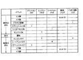
このとき、サイドサポート駆動判断部12は、ステップS8において図6に示すような動作条件テーブルを参照して、ステータス判断を行う。この図6に示す動作条件テーブルは、サイドサポート部100L,100Rの自動調整動作を行う条件(1)〜(3)と、記憶位置を再生する条件と、サイドサポート部100L,100Rの位置を記憶する条件(1)、(2)と、サイドサポート部100L,100Rの位置を消去する条件とが登録されている。
At this time, the side support
例えば、自動調整動作を起動する条件(1)は、イグニッションフラグ、シートベルトフラグ、乗降フラグが同時に「1」となった場合に、自動調整動作を起動させる。また、自動調整動作を起動する条件(2)は、イグニッションフラグ、シートベルトフラグ、ドラポジ調整フラグが同時に「1」となった場合に、自動調整動作を起動させる。更に、自動調整動作を起動する条件(3)は、イグニッションフラグ、シートベルトフラグ、乗降フラグ、ドラポジ調整フラグが同時に「1」となった場合に、自動調整動作を起動させる。一方、自動調整動作を起動させる条件に合致しない場合には、処理はステップS9からステップS10に進められることとなる。 For example, the condition (1) for starting the automatic adjustment operation is to start the automatic adjustment operation when the ignition flag, the seat belt flag, and the getting-on / off flag are simultaneously “1”. The condition (2) for starting the automatic adjustment operation is to start the automatic adjustment operation when the ignition flag, the seat belt flag, and the dry-positive adjustment flag are simultaneously “1”. Further, the condition (3) for starting the automatic adjustment operation is to start the automatic adjustment operation when the ignition flag, the seat belt flag, the boarding / alighting flag, and the dry / positive adjustment flag are simultaneously “1”. On the other hand, if the conditions for starting the automatic adjustment operation are not met, the process proceeds from step S9 to step S10.
ステップS10においては、サイドサポート駆動判断部12によって、予め記憶しておいたサイドサポート部100L,100Rの記憶位置を再生するか否かを判定する。図6に示したような記憶位置を再生する条件に合致し、サイドサポート部100L,100Rの記憶位置を再生する場合には、ステップS12に処理を進めて、サイドサポート駆動制御部10によって、予め記憶しておいた記憶位置となるようにサイドサポート部100L,100Rを動作させる。
In step S10, the side support
また、ステップS11においては、サイドサポート駆動判断部12によって、サイドサポート部100L,100Rを全開位置まで駆動させて記憶位置を記憶するか否かを判定する。図6に示したようなサイドサポート部100L,100Rの位置を記憶して全開する条件の(1)又は(2)に該当し、サイドサポート部100L,100Rの位置を記憶する場合には、ステップS13に処理を進めて、サイドサポート駆動制御部10によってサイドサポート部100L,100Rの位置を記憶し、当該サイドサポート部100L,100Rを全開まで動作させる。このようにサイドサポート部100L,100Rの位置を記憶してサイドサポート部100L,100Rを全開させる場面としては、例えば、サイドサポート部100L,100Rによるサイドサポートが不要と判断された場合が挙げられる。
In step S11, the side support
[実施形態の効果]
以上詳細に説明したように、本発明を適用した車両用シートの制御装置は、車両状態に基づいて、サイドサポート部100L,100Rによる自動調整動作を起動させる場合に、車両状態としてイグニッション状態、エンジン状態、シートベルト状態、ドア開閉状態、車両用シートの状態、又はステアリング位置状態の組み合わせに基づいて、自動調整動作を起動させることを判断する。これにより車両用シートの制御装置によれば、車両状態に基づく使用場面に応じて自動調整動作を起動させることができ、サイドサポート部100L,100Rの自動調整動作によって乗員に煩わしさを与えることを回避できる。
[Effect of the embodiment]
As described above in detail, the vehicle seat control device to which the present invention is applied is based on the vehicle state, and when the automatic adjustment operation by the side support portions 100L and 100R is activated, the vehicle state includes an ignition state, an engine state. Then, based on the combination of the seat belt state, the door open / close state, the vehicle seat state, or the steering position state, it is determined to activate the automatic adjustment operation. As a result, according to the vehicle seat control device, the automatic adjustment operation can be activated according to the use situation based on the vehicle state, and it is avoided that the passengers are bothered by the automatic adjustment operation of the side support portions 100L and 100R. it can.
また、この車両用シートの制御装置は、当該自動調整動作によるサイドサポート部100L,100Rの調整位置の記録及び再生を行う。このような車両用シートの制御装置によれば、例えば図6に示すように、シートベルトが装着された場合に、記憶している前回のサイドサポート部100L,100Rの位置を再生することができる。これにより、乗降による衣服の交換やドライバの変更、もしくは乗降を伴わないドライバの変更においては、サイドサポート部100L,100Rによる自動調整機能を起動し、適切なサイドサポート部100L,100Rの位置を実現できる。 The vehicle seat control device records and reproduces the adjustment positions of the side support portions 100L and 100R by the automatic adjustment operation. According to such a vehicle seat control device, for example, as shown in FIG. 6, when the seat belt is mounted, the stored positions of the previous side support portions 100L and 100R can be reproduced. As a result, when changing clothes or changing drivers by getting on and off, or changing drivers without getting on and off, the automatic adjustment function by the side support parts 100L and 100R can be activated to realize appropriate positions of the side support parts 100L and 100R.
更に、この車両用シートの制御装置によれば、ドア開閉状態に基づいて着座者の乗降を検出し、サイドサポート部100L,100Rの自動調整動作の起動を行うと共に、自動調整動作によるサイドサポート部100L,100Rの調整位置の記録及び再生を行う。これにより車両用シートの制御装置によれば、図6に示した自動調整動作を起動する条件(1)、(3)のように、ドアの開閉によって自動調整動作を起動させることができる。 Further, according to the vehicle seat control device, the seating person gets on and off based on the door open / closed state, the automatic adjustment operation of the side support units 100L, 100R is started, and the side support unit 100L, Recording and playback of the adjustment position of 100R is performed. Thereby, according to the vehicle seat control device, the automatic adjustment operation can be started by opening and closing the door as in the conditions (1) and (3) for starting the automatic adjustment operation shown in FIG.
更にまた、この車両用シートの制御装置によれば、ドア開閉状態に基づいて着座者の乗降と、車両用シート100の状態又はステアリング位置状態の変化とを検出し、当該着座者の乗降と車両用シート100の状態又はステアリング位置状態との何れかに基づいて、車両用シート100の自動調整動作の起動を行うことができる。車両用シートの制御装置によれば、車両用シート100の状態とステアリング位置状態との何れかの変化によってドラポジ調整フラグを「1」とすることにより、図6に示した自動調整動作を起動させる条件(2)、(3)を実現できる。
Furthermore, according to this vehicle seat control device, the boarding / exiting of the seated person and the change of the state of the
更にまた、この車両用シートの制御装置によれば、着座者の乗降と車両用シート100の状態又はステアリング位置状態との何れかの条件に加えて、イグニッション状態がオン状態であることを条件として、自動調整動作によるサイドサポート部100L,100Rの調整位置の記録及び再生を行うことができる。これにより、車両用シートの制御装置によれば、ドライバに最適なサイドサポート部100L,100Rの位置を記録及び再生して、ドライバの煩わしさを回避できる。
Furthermore, according to this vehicle seat control device, on the condition that the ignition state is on in addition to any of the conditions of getting on and off the seated person and the state of the
更にまた、この車両用シートの制御装置によれば、着座者の乗降と車両用シート100の状態又はステアリング位置状態との何れかの条件に加えて、イグニッション状態がオン状態又はシートベルト状態が装着状態であることを条件として、ステップS12,ステップS13にて自動調整動作によるサイドサポート部100L,100Rの調整位置の記録及び再生を行う。したがって、この車両用シートの制御装置によれば、図6に示すような自動調整動作を起動する条件を満たした上で、サイドサポート部100L,100Rの調整位置の記録及び再生を行うことができ、ドライバにとって最適な位置を再生することができる。
Furthermore, according to this vehicle seat control device, the ignition state is on or the seat belt state is worn in addition to any of the conditions of getting on and off of the seated person and the state of the
更にまた、この車両用シートの制御装置によれば、着座者の乗降と車両用シート100の状態又はステアリング位置状態との何れかと、イグニッション状態がオン状態又はシートベルト状態が装着状態である時に行った自動調整動作の後、エンジン状態が停止状態又はシートベルト状態が非装着状態であることを条件として、サイドサポート部100L,100Rの調整位置を記録し、その後に当該サイドサポート部100L,100Rを全開状態とするので、運転していない場合には、必要のないサイドサポートを解消し、ドライバにゆったりとした状況を提供することが可能である。
Furthermore, according to this vehicle seat control device, the
更にまた、この車両用シートの制御装置によれば、エンジン状態が停止状態又はシートベルト状態が非装着状態であることを条件として、サイドサポート部100L,100Rの調整位置を記録し、その後に当該サイドサポート部100L,100Rを全開状態とした後に、ドア開閉状態に基づいて着座者が降車したと判断した場合に、図6に示す記憶消去条件に従ってサイドサポート部100L,100Rの調整位置を消去するので、あるドライバが降車し、次に乗車するドライバが不定となることに対し、次のドライバのために自動調整機能が必要となるように設定することができる。 Furthermore, according to the vehicle seat control device, the adjustment positions of the side support portions 100L and 100R are recorded on condition that the engine state is the stop state or the seat belt state is the non-wearing state, and then the side support is performed. When it is determined that the seated person gets off based on the door open / close state after the portions 100L and 100R are fully opened, the adjustment positions of the side support portions 100L and 100R are erased according to the memory erasure condition shown in FIG. It can be set so that an automatic adjustment function is required for the next driver while the driver gets off and the next driver gets indefinite.
更にまた、この車両用シートの制御装置によれば、ドア開閉状態に基づいて着座者が乗車し、シートベルトが装着状態であると判断した場合に、記憶していたサイドサポート部100L,100Rの調整位置を再生させる。これにより、ドライバ変更が検出されない場合は、ドライバが座席においてシートベルトを外して休息する場合などであり、サイドサポート部100L,100Rの自動調整動作を必要としないため、前回位置を再生することで必要十分である。 Furthermore, according to this vehicle seat control device, when the seated person gets on the basis of the door open / closed state and determines that the seat belt is in the mounted state, the stored side support portions 100L and 100R are adjusted. Play the position. Thus, when the driver change is not detected, it is necessary for the driver to rest with the seat belt removed from the seat, and since the automatic adjustment operation of the side support portions 100L and 100R is not required, it is necessary to reproduce the previous position. It is enough.
以上のように、ドライバの乗降、ドライバ位置の変更、車内でのイグニッション、エンジン、シートベルトの状態から条件判断することにより、サイドサポート部100L,100Rの自動調整機能と記憶位置の再生機能とを効率的に使い分けることが可能となる。これにより、サイドサポート部100L,100Rが自動調整動作によってドライバを挟み込んで煩わしさを与えることなく、必要時のみに自動調整動作を起動させることができ、常に適切なサイドサポートを提供可能となる。 As described above, it is possible to efficiently use the automatic adjustment function of the side support units 100L and 100R and the reproduction function of the storage position by judging the conditions based on the boarding / alighting of the driver, the change of the driver position, the ignition in the vehicle, the engine, and the seat belt. Can be used properly. Accordingly, the side support units 100L and 100R can activate the automatic adjustment operation only when necessary without causing the driver to be bothered by the automatic adjustment operation and can always provide appropriate side support.
なお、上述の実施の形態は本発明の一例である。このため、本発明は、上述の実施形態に限定されることはなく、この実施の形態以外であっても、本発明に係る技術的思想を逸脱しない範囲であれば、設計等に応じて種々の変更が可能であることは勿論である。 The above-described embodiment is an example of the present invention. For this reason, the present invention is not limited to the above-described embodiment, and various modifications can be made depending on the design and the like as long as the technical idea according to the present invention is not deviated from this embodiment. Of course, it is possible to change.
1 リフタ駆動機構
2 リクライニング駆動機構
3 スライド駆動機構
4 ステアリング駆動機構
5 サイドサポート駆動機構
6 リフタ駆動制御部
7 リクライニング駆動制御部
8 スライド駆動制御部
9 ステアリング駆動制御部
10 サイドサポート駆動制御部
11 ドライバ位置駆動判断部
12 サイドサポート駆動判断部
13 サイドサポート駆動入力部
14 イグニッション状態入力部
15 エンジン状態入力部
16 シートベルト状態入力部
17 ドア状態入力部
18 イグニッション状態判断部
19 エンジン状態判断部
20 シートベルト状態判断部
21 ドア状態判断部
22 車両情報判断部
100 車両用シート
100B 背面部
100H ヘッドレスト
100L,100R サイドサポート部
110L,110R サイドサポート可動部
111 シートフレーム
112L、112R 回転支持部
114L、114R サイドサポートフレーム
115L、115R、116、117L、117R リンク
118L 左側モータ
118R 右側モータ
119 ゲージ
121 クッション支持スプリング
DESCRIPTION OF
Claims (9)
車両状態を判断する車両状態判断手段と、
前記車両状態判断手段により判断された車両状態に基づいて、前記駆動手段によって前記右側支持部及び左側支持部の位置を調整させて着座者を支持する自動調整動作を起動させる制御手段とを有し、
前記制御手段は、前記車両状態としてイグニッション状態、エンジン状態、シートベルト状態、ドア開閉状態、車両用シートの状態、又はステアリング位置状態の組み合わせに基づいて、前記自動調整動作を起動させることを特徴とする車両用シートの制御装置。 Drive means for driving a right support and a left support that are included in a vehicle seat on which a seated person is seated and that support the upper body of the seated person seated on the vehicle seat from both sides;
Vehicle state determination means for determining the vehicle state;
Control means for starting an automatic adjustment operation for supporting a seated person by adjusting the positions of the right support part and the left support part by the driving means based on the vehicle state determined by the vehicle state determination means. ,
The control means activates the automatic adjustment operation based on a combination of an ignition state, an engine state, a seat belt state, a door opening / closing state, a vehicle seat state, or a steering position state as the vehicle state. A vehicle seat control device.
Priority Applications (1)
| Application Number | Priority Date | Filing Date | Title |
|---|---|---|---|
| JP2008167210A JP5422929B2 (en) | 2008-06-26 | 2008-06-26 | Control device for vehicle seat |
Applications Claiming Priority (1)
| Application Number | Priority Date | Filing Date | Title |
|---|---|---|---|
| JP2008167210A JP5422929B2 (en) | 2008-06-26 | 2008-06-26 | Control device for vehicle seat |
Publications (2)
| Publication Number | Publication Date |
|---|---|
| JP2010006215A true JP2010006215A (en) | 2010-01-14 |
| JP5422929B2 JP5422929B2 (en) | 2014-02-19 |
Family
ID=41587198
Family Applications (1)
| Application Number | Title | Priority Date | Filing Date |
|---|---|---|---|
| JP2008167210A Expired - Fee Related JP5422929B2 (en) | 2008-06-26 | 2008-06-26 | Control device for vehicle seat |
Country Status (1)
| Country | Link |
|---|---|
| JP (1) | JP5422929B2 (en) |
Citations (4)
| Publication number | Priority date | Publication date | Assignee | Title |
|---|---|---|---|---|
| JPH05229373A (en) * | 1992-02-19 | 1993-09-07 | Mitsubishi Motors Corp | Side support control device for seat |
| JPH0667702B2 (en) * | 1988-03-23 | 1994-08-31 | 株式会社豊田自動織機製作所 | Seat with automatic side support |
| JP2006015117A (en) * | 2004-06-01 | 2006-01-19 | Olympus Corp | Endoscope apparatus |
| JP2006151117A (en) * | 2004-11-26 | 2006-06-15 | Toyota Motor Corp | Vehicular seat control device |
-
2008
- 2008-06-26 JP JP2008167210A patent/JP5422929B2/en not_active Expired - Fee Related
Patent Citations (4)
| Publication number | Priority date | Publication date | Assignee | Title |
|---|---|---|---|---|
| JPH0667702B2 (en) * | 1988-03-23 | 1994-08-31 | 株式会社豊田自動織機製作所 | Seat with automatic side support |
| JPH05229373A (en) * | 1992-02-19 | 1993-09-07 | Mitsubishi Motors Corp | Side support control device for seat |
| JP2006015117A (en) * | 2004-06-01 | 2006-01-19 | Olympus Corp | Endoscope apparatus |
| JP2006151117A (en) * | 2004-11-26 | 2006-06-15 | Toyota Motor Corp | Vehicular seat control device |
Also Published As
| Publication number | Publication date |
|---|---|
| JP5422929B2 (en) | 2014-02-19 |
Similar Documents
| Publication | Publication Date | Title |
|---|---|---|
| JP7513932B2 (en) | Vehicle seats | |
| JP6675276B2 (en) | Vehicle seat device | |
| JP4376936B2 (en) | Vehicle seat device | |
| JP5548058B2 (en) | Control device for vehicle seat | |
| KR102153216B1 (en) | Multi-position seat for vehicle | |
| JPH0796784A (en) | Driving attitude adjuster of vehicle | |
| JP2844248B2 (en) | Power rotary seat control method and power rotary seat control device | |
| JP5422929B2 (en) | Control device for vehicle seat | |
| JP2008132843A (en) | Seat device for vehicle | |
| JP2019001315A (en) | Vehicle seat | |
| JPH06211077A (en) | Eat device for vehicle | |
| JPH115479A (en) | Vehicular seat | |
| JPH05330368A (en) | Motor control method and device for power seat | |
| KR20140065299A (en) | Apparatus for adjusting driver's seat and method thereof | |
| JP4244773B2 (en) | Vehicle seat | |
| JP2589107B2 (en) | Vehicle seat side support control method and side support device | |
| JPH03271031A (en) | Method and device for controlling power seat motor | |
| JP2810822B2 (en) | Vehicle seat | |
| JP2819138B2 (en) | Headrest control method, headrest control device, and headrest drive mechanism | |
| JP2008012930A (en) | Seat device | |
| JP7420455B2 (en) | vehicle seat | |
| JP4517883B2 (en) | Vehicle seat | |
| JPS61207237A (en) | Rotary car seat | |
| JP2590875B2 (en) | Side support control device | |
| WO2016152583A1 (en) | Drive control system for front passenger seat, and control device |
Legal Events
| Date | Code | Title | Description |
|---|---|---|---|
| A621 | Written request for application examination |
Free format text: JAPANESE INTERMEDIATE CODE: A621 Effective date: 20110527 |
|
| A977 | Report on retrieval |
Free format text: JAPANESE INTERMEDIATE CODE: A971007 Effective date: 20130214 |
|
| A131 | Notification of reasons for refusal |
Free format text: JAPANESE INTERMEDIATE CODE: A131 Effective date: 20130219 |
|
| A521 | Request for written amendment filed |
Free format text: JAPANESE INTERMEDIATE CODE: A523 Effective date: 20130418 |
|
| TRDD | Decision of grant or rejection written | ||
| A01 | Written decision to grant a patent or to grant a registration (utility model) |
Free format text: JAPANESE INTERMEDIATE CODE: A01 Effective date: 20131029 |
|
| A61 | First payment of annual fees (during grant procedure) |
Free format text: JAPANESE INTERMEDIATE CODE: A61 Effective date: 20131111 |
|
| R150 | Certificate of patent or registration of utility model |
Free format text: JAPANESE INTERMEDIATE CODE: R150 Ref document number: 5422929 Country of ref document: JP Free format text: JAPANESE INTERMEDIATE CODE: R150 |
|
| LAPS | Cancellation because of no payment of annual fees |