JP2010006098A - Power slide device of vehicular seat - Google Patents
Power slide device of vehicular seat Download PDFInfo
- Publication number
- JP2010006098A JP2010006098A JP2008164113A JP2008164113A JP2010006098A JP 2010006098 A JP2010006098 A JP 2010006098A JP 2008164113 A JP2008164113 A JP 2008164113A JP 2008164113 A JP2008164113 A JP 2008164113A JP 2010006098 A JP2010006098 A JP 2010006098A
- Authority
- JP
- Japan
- Prior art keywords
- screw rod
- load transmission
- vehicle seat
- load
- slide device
- Prior art date
- Legal status (The legal status is an assumption and is not a legal conclusion. Google has not performed a legal analysis and makes no representation as to the accuracy of the status listed.)
- Granted
Links
- 230000005540 biological transmission Effects 0.000 claims abstract description 133
- 238000000034 method Methods 0.000 claims description 10
- 230000002265 prevention Effects 0.000 claims description 4
- 238000005520 cutting process Methods 0.000 claims description 2
- 238000003780 insertion Methods 0.000 description 13
- 230000037431 insertion Effects 0.000 description 13
- 238000010521 absorption reaction Methods 0.000 description 3
- 239000000463 material Substances 0.000 description 3
- 229920003002 synthetic resin Polymers 0.000 description 3
- 239000000057 synthetic resin Substances 0.000 description 3
- 238000005452 bending Methods 0.000 description 2
- 238000007906 compression Methods 0.000 description 2
- 230000008878 coupling Effects 0.000 description 2
- 238000010168 coupling process Methods 0.000 description 2
- 238000005859 coupling reaction Methods 0.000 description 2
- 238000010586 diagram Methods 0.000 description 2
- 230000000694 effects Effects 0.000 description 2
- 239000002184 metal Substances 0.000 description 2
- 230000001105 regulatory effect Effects 0.000 description 2
- 230000006835 compression Effects 0.000 description 1
- 230000002401 inhibitory effect Effects 0.000 description 1
- 238000009434 installation Methods 0.000 description 1
- 239000002994 raw material Substances 0.000 description 1
Images


Classifications
-
- B—PERFORMING OPERATIONS; TRANSPORTING
- B60—VEHICLES IN GENERAL
- B60N—SEATS SPECIALLY ADAPTED FOR VEHICLES; VEHICLE PASSENGER ACCOMMODATION NOT OTHERWISE PROVIDED FOR
- B60N2/00—Seats specially adapted for vehicles; Arrangement or mounting of seats in vehicles
- B60N2/02—Seats specially adapted for vehicles; Arrangement or mounting of seats in vehicles the seat or part thereof being movable, e.g. adjustable
- B60N2/04—Seats specially adapted for vehicles; Arrangement or mounting of seats in vehicles the seat or part thereof being movable, e.g. adjustable the whole seat being movable
- B60N2/06—Seats specially adapted for vehicles; Arrangement or mounting of seats in vehicles the seat or part thereof being movable, e.g. adjustable the whole seat being movable slidable
- B60N2/067—Seats specially adapted for vehicles; Arrangement or mounting of seats in vehicles the seat or part thereof being movable, e.g. adjustable the whole seat being movable slidable by linear actuators, e.g. linear screw mechanisms
-
- B—PERFORMING OPERATIONS; TRANSPORTING
- B60—VEHICLES IN GENERAL
- B60N—SEATS SPECIALLY ADAPTED FOR VEHICLES; VEHICLE PASSENGER ACCOMMODATION NOT OTHERWISE PROVIDED FOR
- B60N2/00—Seats specially adapted for vehicles; Arrangement or mounting of seats in vehicles
- B60N2/02—Seats specially adapted for vehicles; Arrangement or mounting of seats in vehicles the seat or part thereof being movable, e.g. adjustable
- B60N2/04—Seats specially adapted for vehicles; Arrangement or mounting of seats in vehicles the seat or part thereof being movable, e.g. adjustable the whole seat being movable
- B60N2/06—Seats specially adapted for vehicles; Arrangement or mounting of seats in vehicles the seat or part thereof being movable, e.g. adjustable the whole seat being movable slidable
- B60N2/07—Slide construction
- B60N2/0702—Slide construction characterised by its cross-section
- B60N2/0705—Slide construction characterised by its cross-section omega-shaped
Abstract
Description
本発明は、車両用シートをモータ駆動の送りねじ機構で前後方向に移動させるパワースライド装置に関する。 The present invention relates to a power slide device that moves a vehicle seat in the front-rear direction by a motor-driven feed screw mechanism.
車両用シートスライド装置は、車両床面に前後方向に向けて固定されるロアレールに、シートに固定されるアッパレールを摺動自在に係合させる基本構造を有する。この車両用シートスライド装置は、アッパレールとロワレールの一方に、該レールの延長方向に向けてモータ駆動のスクリューロッドを回動自在に支持する一方、他方にこのスクリューロッドのナット螺合部に螺合するナット部材を固定することでパワー化されている。 The vehicle seat slide device has a basic structure in which an upper rail fixed to a seat is slidably engaged with a lower rail fixed to a vehicle floor surface in the front-rear direction. In this vehicle seat slide device, a motor-driven screw rod is rotatably supported on one of an upper rail and a lower rail in the extending direction of the rail, and the other is screwed into a nut screwing portion of the screw rod. It is made power by fixing the nut member.
スクリューロッドは、アッパレールとロアレールのいずれか一方の一端部(一般的に前端部)に設けたギヤボックスと後端部に設けた軸受部材との間に回転自在に支持されている。さらに、スクリューロッドを支持したレールには、該スクリューロッドを回転自在に支持し、かつ衝突時の荷重を分散させギヤボックスに直接伝達されないようにする荷重伝達部材(荷重伝達ブラケット)を固定することが行われている。
しかしながら、従来装置は、スクリューロッドに、例えば衝突時に挫屈荷重が加わると、スクリューロッドと荷重伝達部材が実質的に軸方向の一点(狭い範囲)で結合されているため、スクリューロッドが大きく挫屈し、その結果、十分な耐衝撃力を得ることができないという問題点があった。 However, in the conventional device, when a buckling load is applied to the screw rod, for example, at the time of a collision, the screw rod and the load transmission member are substantially coupled at one point (narrow range) in the axial direction. As a result, there is a problem that sufficient impact resistance cannot be obtained.
本発明は、以上の問題意識に基づき、荷重伝達部材を介して衝突荷重がスクリューロッドに加わったとき、スクリューロッドの挫屈量を小さく抑制し、耐衝撃力を向上させることができる車両用シートのパワースライド装置を得ることを目的とする。 The present invention is based on the above problem awareness and, when a collision load is applied to the screw rod through the load transmission member, the amount of buckling of the screw rod can be suppressed to be small and the impact resistance can be improved. The purpose is to obtain a power slide device.
本発明は、スクリューロッド支持レールには、前後方向(スクリューロッドの延長方向)に離間した一対の荷重伝達部材を設け、スクリューロッドには、この一対の荷重伝達部材内面にそれぞれ当接する荷重受け部材を設けることで、スクリューロッドが軸力を受けたときの挫屈支点を複数とし、もって、スクリューロッドの挫屈方向を限定し、挫屈量を小さく抑制するという着眼に基づいてなされたものである。 In the present invention, the screw rod support rail is provided with a pair of load transmission members spaced in the front-rear direction (extension direction of the screw rod), and the screw rods are respectively contacted with the inner surfaces of the pair of load transmission members. By providing a plurality of buckling fulcrums when the screw rod receives an axial force, the buckling direction of the screw rod is limited and the amount of buckling is suppressed to a small extent. is there.
本発明による車両用シートのパワースライド装置は、車両床面に配設されるロアレール;このロアレールに摺動自在に係合しシート側に配設されるアッパレール;アッパレールとロアレールのいずれか一方の一端部に設けたギヤボックスと他端部に設けた軸受部材との間に回転自在に支持され、ギヤボックスにより回転駆動されるスクリューロッド;及びこのスクリューロッドに螺合され、アッパレールとロアレールの他方に固定された送りナット;スクリューロッド支持レールに、その延長方向に離間した位置で保持された一対の荷重伝達部材;及びこの一対の荷重伝達部材の間に位置させて上記スクリューロッドに軸方向位置を規制して設けた少なくとも一つの荷重受け部材;を有しており、送りナット支持レールとスクリューロッド支持レールは互いに対向する開口部を備えていて、一対の荷重伝達部材は、スクリューロッドよりも、スクリューロッド支持レールの開口部側に位置する着力部を備えていることを特徴としている。この着力部は、常時はスクリューロッドに接触せず、荷重伝達部材とスクリューロッドの少なくとも一方が変形したときに互いに接触する。 A power slide device for a vehicle seat according to the present invention includes: a lower rail disposed on a vehicle floor; an upper rail slidably engaged with the lower rail and disposed on a seat side; one end of either the upper rail or the lower rail A screw rod that is rotatably supported by a gear box provided at the other end and a bearing member provided at the other end, and is driven to rotate by the gear box; and is screwed into the screw rod to be connected to the other of the upper rail and the lower rail. A fixed feed nut; a pair of load transmission members held on a screw rod support rail at positions spaced apart in the extension direction; and an axial position of the screw rod positioned between the pair of load transmission members. At least one load receiving member provided in a regulated manner; feed nut support rail and screw rod support The rail is provided with openings facing each other, and the pair of load transmission members are provided with a force applying portion located on the opening side of the screw rod support rail rather than the screw rod. The force applying portion does not normally contact the screw rod, but contacts each other when at least one of the load transmitting member and the screw rod is deformed.
本発明による車両用シートのパワースライド装置では、シートから車両への荷重伝達は、一方の荷重伝達部材、荷重受け部材及び他方の荷重伝達部材の順に行われる。 In the power slide device for a vehicle seat according to the present invention, load transmission from the seat to the vehicle is performed in the order of one load transmission member, a load receiving member, and the other load transmission member.
荷重受け部材は、例えば次のような態様で一対の荷重伝達部材の間に該一対の荷重伝達部材内面に当接するように設けることができる。
1.スクリューロッドに螺合させ該スクリューロッドに固定した単一のナット部材。この単一のナット部材によれば、構成を単純にできる。
2.この単一のナット部材には、雌ねじを有しない小径段部を設け、スクリューロッドには、この小径段部に対応する雄ねじを有しない小径段部を設けることができる。このように小径段部を設けると、スクリューロッドとナット部材の軸受面積を拡大することができる。
3.スクリューロッドに螺合させ、該スクリューロッドに固定した一対のナット部材。一対のナット部材によれば、一対の荷重伝達部材との寸法調整を容易に行うことができる。
4.スクリューロッドに形成した雄ねじを有しない小径段部に嵌めたワッシャ部材と、スクリューロッドに螺合させ該スクリューロッドに固定したナット部材。このワッシャ部材とナット部材によれば、軸受面積を拡大でき、かつ一対の荷重伝達部材との寸法調整を容易に行うことができる。
5.いずれの形態のナット部材であっても、スクリューロッドへの螺合前に、その雌ねじ部の内径を呼び径より小径に塑性変形させてスクリューロッドとの回転抵抗を増大させる緩み止め加工を施すことが望ましい。このように緩み止め加工を施すと、かしめ作業を省略することができ、生産性が増す。
For example, the load receiving member can be provided between the pair of load transmission members so as to contact the inner surfaces of the pair of load transmission members in the following manner.
1. A single nut member screwed into the screw rod and fixed to the screw rod. According to this single nut member, the configuration can be simplified.
2. The single nut member can be provided with a small-diameter step portion having no female screw, and the screw rod can be provided with a small-diameter step portion having no male screw corresponding to the small-diameter step portion. When the small-diameter step portion is provided in this manner, the bearing areas of the screw rod and the nut member can be increased.
3. A pair of nut members screwed into the screw rod and fixed to the screw rod. According to the pair of nut members, dimensional adjustment with the pair of load transmission members can be easily performed.
4). A washer member fitted to a small diameter step portion having no male screw formed on the screw rod, and a nut member screwed to the screw rod and fixed to the screw rod. According to the washer member and the nut member, the bearing area can be enlarged, and the dimensional adjustment with the pair of load transmission members can be easily performed.
5). Regardless of the type of nut member, before screwing into the screw rod, the inner diameter of the female thread portion should be plastically deformed to a smaller diameter than the nominal diameter to prevent loosening that increases the rotational resistance with the screw rod. Is desirable. When the loosening prevention process is performed in this manner, the caulking work can be omitted, and the productivity is increased.
荷重伝達部材とスクリューロッドの固定手段には、かしめ、接着、ノックピンのいずれかを用いることができる。 As a means for fixing the load transmitting member and the screw rod, any one of caulking, adhesion, and a knock pin can be used.
ギヤボックスは、荷重伝達部材に支持することができる。荷重伝達部材に支持すれば、構成を単純化することができる。 The gear box can be supported by the load transmission member. If supported by the load transmission member, the configuration can be simplified.
ギヤボックスは、別の態様では、荷重伝達部材とは別部材からなり該荷重伝達部材に結合されたギヤボックス支持ブラケットに支持してもよい。この態様によれば、ギヤボックスの保持剛性を高めることができる。 In another aspect, the gear box may be supported by a gear box support bracket which is a member different from the load transmission member and is coupled to the load transmission member. According to this aspect, the holding rigidity of the gear box can be increased.
さらに別の態様では、ギヤボックスは、スクリューロッド支持レールに支持し、荷重伝達部材はギヤボックスの支持に関与させないこともできる。スクリューロッド支持レールにギヤボックスを支持すると、該支持レールに対するギヤボックスの位置精度を高めることができる。 In yet another aspect, the gear box may be supported by a screw rod support rail and the load transmitting member may not be involved in supporting the gear box. If the gear box is supported by the screw rod support rail, the positional accuracy of the gear box with respect to the support rail can be increased.
一対の荷重伝達部材のスクリューロッド挿通穴の少なくとも一方には、スクリューロッドをより安定的に回転自在に支持するため、該ロッドを相対回転自在に支持する合成樹脂製のスリーブを嵌め、スクリューロッドの軸受精度を高めることができる。 At least one of the screw rod insertion holes of the pair of load transmission members is fitted with a synthetic resin sleeve that supports the rod in a relatively rotatable manner in order to support the screw rod in a more stable and rotatable manner. Bearing accuracy can be increased.
スクリューロッド支持レールに設ける一対の荷重伝達部材の設置態様には自由度があり、別々の荷重伝達部材をスクリューロッド支持レールに固定すること、あるいは一対の荷重伝達部材を予め結合することが可能である。予め結合する態様では、一対の荷重伝達部材(荷重伝達壁)と、この一対の荷重伝達部材を接続しスクリューロッド支持レールに固定される固定壁とを有するコ字状の荷重伝達ブラケットを用いることができる。コ字状の荷重伝達ブラケットによれば、部品点数を削減し、一対の荷重伝達部材間の精度を高めることができる。 The installation mode of the pair of load transmission members provided on the screw rod support rail has a degree of freedom, and it is possible to fix separate load transmission members to the screw rod support rail or to couple the pair of load transmission members in advance. is there. In the pre-coupling mode, a U-shaped load transmission bracket having a pair of load transmission members (load transmission walls) and a fixed wall connected to the pair of load transmission members and fixed to the screw rod support rail is used. Can do. According to the U-shaped load transmission bracket, the number of parts can be reduced and the accuracy between the pair of load transmission members can be increased.
本発明による車両用シートのパワースライド装置では、一対の荷重伝達部材は、送りナットに近い側の荷重伝達部材の方が、遠い側の荷重伝達部材よりも、上記スクリューロッド支持ブラケットまたは荷重伝達部材を介して加わる車両前後方向の力によって変形しにくい態様で支持し、またはそのような変形特性が得られる特性を与え、該一対の荷重伝達部材の着力部は、該荷重伝達部材が変形したとき、スクリューロッドに当接して変形の支点を与えることが好ましい。 In the power slide device for a vehicle seat according to the present invention, the pair of load transmission members are such that the load transmission member closer to the feed nut is closer to the screw rod support bracket or the load transmission member than the load transmission member on the far side. When the load transmitting member is deformed, it is supported in such a manner that it is not easily deformed by the force in the longitudinal direction of the vehicle applied through the vehicle, or such a deformation characteristic is obtained. It is preferable to contact the screw rod to provide a fulcrum for deformation.
具体的には、一対の荷重伝達部材のうち、送りナットに近い側の荷重伝達部材には複数の支持突起を設けて、この支持突起をスクリューロッド支持レールに形成した複数の固定穴に嵌合させ、遠い側の荷重伝達部材にはこのような支持突起(及び固定穴)を設けない態様が可能である。この構成によれば、支持突起を設ける側の荷重伝達部材の支持強度を、設けない側の荷重伝達部材の支持強度よりも明確に高くすることができる。 Specifically, among the pair of load transmission members, the load transmission member closer to the feed nut is provided with a plurality of support protrusions, and these support protrusions are fitted into the plurality of fixing holes formed in the screw rod support rail. Further, it is possible to adopt a mode in which such a support protrusion (and fixing hole) is not provided on the far side load transmission member. According to this configuration, the support strength of the load transmission member on the side where the support protrusion is provided can be clearly higher than the support strength of the load transmission member on the side where the support protrusion is not provided.
あるいは、一対の荷重伝達部材にはそれぞれ複数の支持突起を設け、スクリューロッド支持レールには、これら支持突起を嵌合させる複数の固定穴を形成し、この一対の荷重伝達部材の支持突起とスクリューロッド支持レールの固定穴との車両前後方向のクリアランスを、送りナットに遠い側の荷重伝達部材側のそれが近い側の荷重伝達部材側のそれより大きくなるようにしてもよい。この構成によれば、クリアランスの大小によって変形量の管理が可能である。 Alternatively, each of the pair of load transmission members is provided with a plurality of support protrusions, and the screw rod support rail is formed with a plurality of fixing holes for fitting the support protrusions. The clearance in the vehicle longitudinal direction with respect to the fixing hole of the rod support rail may be larger than that on the side of the load transmission member on the side farther from the feed nut than on the side of the load transmission member. According to this configuration, the amount of deformation can be managed depending on the clearance size.
具体的な態様では、ギヤボックス、荷重伝達部材及び送りナットが露見しないようにして外観を向上させるため、スクリューロッドは可動のアッパレールに支持し、送りナットは不動のロワレールに固定するのが実際的である。またギヤボックスはアッパレールの前端部に設けるのが好ましい。一対の荷重伝達部材は、送りナットの後方に配置することも可能であるが、スクリューロッドの挫屈方向をより好ましくコントロールするには、ギヤボックスと送りナットの間に設ける、つまり、ギヤボックス、荷重受け部材及び送りナットを、この順番に並べるのが実際的である。 In a specific embodiment, it is practical to support the screw rod on the movable upper rail and fix the feed nut to the stationary lower rail in order to improve the appearance so that the gear box, load transmission member and feed nut are not exposed. It is. The gear box is preferably provided at the front end of the upper rail. The pair of load transmission members can be arranged behind the feed nut. However, in order to more preferably control the buckling direction of the screw rod, it is provided between the gear box and the feed nut, that is, the gear box, It is practical to arrange the load receiving member and the feed nut in this order.
スクリューロッドには、ねじ切り加工を施す前の丸棒状態において、径方向に圧縮荷重を加える絞り加工を施し、剛性を高めることが好ましい。 The screw rod is preferably subjected to a drawing process in which a compressive load is applied in the radial direction in a round bar state before the thread cutting process to increase rigidity.
本発明は、スクリューロッド、送りナットの他に、衝突時の荷重をスクリューナットに伝達する一対の荷重伝達部材をスクリューロッド支持レールに保持し、この一対の荷重伝達部材の間に位置させてスクリューロッドに軸方向位置を規制して少なくとも一つの荷重受け部材を設けたものであって、送りナット支持レールとスクリューロッド支持レールは互いに対向する開口部を備えていて、一対の荷重伝達部材は、スクリューロッドよりも、スクリューロッド支持レールの開口部側に位置する着力部を備えているので、スクリューロッドが軸力を受けたときの挫屈支点を複数とし、もって、スクリューロッドの挫屈量を小さく抑制することができる。すなわち、一対の荷重伝達部材の着力部は、常時はスクリューロッドに接触せず、荷重伝達部材とスクリューロッドの少なくとも一方が変形したときに互いに接触して挫屈支点となる。 In the present invention, in addition to a screw rod and a feed nut, a pair of load transmission members that transmit a load at the time of collision to the screw nut are held by a screw rod support rail, and are positioned between the pair of load transmission members. The rod is provided with at least one load receiving member by regulating the axial position, the feed nut support rail and the screw rod support rail are provided with openings facing each other, and the pair of load transmission members are: Since it has an attachment portion located on the opening side of the screw rod support rail rather than the screw rod, there are a plurality of buckling fulcrums when the screw rod receives axial force, so that the amount of buckling of the screw rod can be reduced. It can be suppressed small. In other words, the force applying portions of the pair of load transmitting members do not normally contact the screw rod, but contact each other when at least one of the load transmitting member and the screw rod is deformed to serve as a buckling fulcrum.
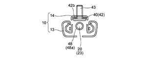
車両用シートスライド装置は、図13に示すように、車両用シートSと床面Fとの間に位置し車両前後方向に延びる左右一対のシートトラック10を有する。左右のシートトラック10は、同一(対称)構造であり、床面Fに前後のブラケット11、12で固定されるロアレール13と、シートSに固定されるアッパレール14とを有し、このロアレール13とアッパレール14が摺動自在に嵌まっている。ロアレール13とアッパレール14は、互いに対向する開口部を備えている。
As shown in FIG. 13, the vehicle seat slide device includes a pair of left and right seat tracks 10 that are located between the vehicle seat S and the floor surface F and extend in the vehicle front-rear direction. The left and right seat tracks 10 have the same (symmetric) structure, and have a
ロアレール13には、図1に示すように、固定ボルト15を介して軸線を前後方向に向けた送りナット16が固定されている。この送りナット16は、金属製のアウタケーシング16a内に、吸振用のゴムシート16bを介して、合成樹脂製のナット16cを挿入してなっている。ロアレール13は、送りナット固定レールである。
As shown in FIG. 1, a
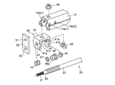
これに対し、アッパレール14には、この送りナット16に螺合するスクリューロッド20が回転自在に支持されている。すなわち、アッパレール(スクリューロッド支持レール)14には、その前端部と後端部に、スクリューロッド20の前端部と後端部を回転自在に支持するギヤボックス30と軸受部材17が設けられている。図1は、アッパレール14(シートS)のロアレール13に対する前方移動端を示している(図の左方が前方である)。
On the other hand, on the
スクリューロッド20には、その前端部にセレーション部21が形成されており、ギヤボックス30内には、このセレーション部21と相対回転不能に係合するセレーション穴32aを軸部に有するウォームホイル32が回転自在に支持されている。ウォームホイル32は、軸線を車両左右方向に向けたウォーム33と噛み合っていて、該ウォーム33が正逆に回転すると、ウォームホイル32が正逆に回転し、セレーション部21(スクリューロッド20)が正逆に回転する。ギヤボックス30は、金属製のアウタケーシング30a内に吸振用のゴムシート30bを介して機構部30cが支持されている。
The
左右のアッパレール14のギヤボックス30内のウォーム33は、連動機構によって連動して回転するものであり、この連動回転により、左右のアッパレール14のスクリューロッド20が正逆に回転する。すると、スクリューロッド20は、ロアレール13に固定した送りナット16と螺合しているため、アッパレール14(シートS)が前後に移動する。
The
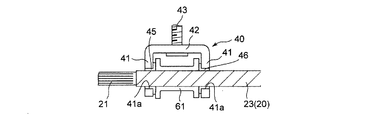
アッパレール14には、ギヤボックス30と送りナット16との間に位置させて、荷重伝達ブラケット40が固定されている。この荷重伝達ブラケット40は、図1ないし図4に示すように、スクリューロッド20の軸方向(シートトラック10の長手方向)に離間した一対の荷重伝達壁(荷重伝達部材)41と、この荷重伝達壁41を接続するアッパレール14に沿う固定壁42を有するコ字状をしており、一対の荷重伝達壁41にはそれぞれ、スクリューロッド20を挿通する挿通穴41aが穿設されている。挿通穴41aは、常時はスクリューロッド20とは非接触であるが、その図の下方の面(スクリューロッド20よりもアッパレール14の開口部側に位置する面)は、荷重伝達壁41とスクリューロッド20の少なくとも一方が変形したときに、該スクリューロッド20の変形(挫屈)の方向を定める着力部として作用する。
A
この荷重伝達ブラケット40は、固定壁42からアッパレール14に挿通した固定ボルト43と、この固定ボルト43に螺合した固定ナット44により、該アッパレール14に固定されている。荷重伝達ブラケット40の一対の荷重伝達壁41にはそれぞれ、図2、図3に示すように、アッパレール14に穿設した固定穴14aに嵌合支持される支持突起41bが形成されている。また、荷重伝達ブラケット40の固定壁42とアッパレール14との間には、吸振用のゴムシート42bが挟着されている。
The
荷重伝達ブラケット40のギヤボックス30側の面には、ギヤボックス支持ブラケット50が溶接固定されており、このギヤボックス支持ブラケット50には、支持穴51及び固定ボルト52を介してギヤボックス30が支持されている。またこのギヤボックス支持ブラケット50には、スクリューロッド20を挿通する挿通穴53が穿設されている。
A gear
このギヤボックス支持ブラケット50の挿通穴53と一方の荷重伝達壁41の挿通穴41aには、両穴に跨らせて、低摩擦性合成樹脂材料からなるスリーブ45が嵌められており、他方の荷重伝達壁41の挿通穴41aには、同様のスリーブ46が嵌められている。
A
スクリューロッド20には、図1、図2に示すように、セレーション部21に続けて、雄ねじを有しない小径段部(小径無ねじ部)22とねじ部23が形成されている。荷重伝達ブラケット40の一対の荷重伝達壁41の間には、この小径段部22に嵌められて、一方の荷重伝達壁41(ギヤボックス30側の荷重伝達壁41)の内面と該小径段部22の段部との間に軸方向移動を規制して挟着(当接)されるワッシャ(荷重受け部材)47と、ねじ部23に螺合されて他方の荷重伝達壁41(送りナット16側の荷重伝達壁41)に当接するナット部材(荷重受け部材)48とが位置している。ナット部材48は、薄肉筒状部48aを備えており、この薄肉円筒部48aを潰す(塑性変形させる)ことで、ナット部材48がスクリューロッド20に固定されている。一対の荷重伝達壁41の挿通穴41aに嵌めたスリーブ45と46のうち、スリーブ45はスクリューロッド20の小径段部22に最小のクリアランスで嵌合してスクリューロッド20を回転自在に支持する。一方スリーブ46は、小径段部22との間に常時は接触しないクリアランスが設定されている。ナット部材48は、常時スクリューロッド20と一体に回転するが、ワッシャ47は、スクリューロッド20に対する軸方向位置が規制されているので、スクリューロッド20と一体に回転しても相対回転してもよい。このワッシャ47とナット部材48によれば、軸受面積を拡大でき、かつ一対の荷重伝達部材41との寸法調整を容易に行うことができる。
As shown in FIGS. 1 and 2, the
以上のシートスライド装置は、衝突荷重が加わると、アッパレール14がロアレール13に対して相対的に移動しようとし、その荷重は、荷重伝達ブラケット40の一対の荷重伝達壁41から、ワッシャ47またはナット部材48に伝達され、スクリューロッド20に加わる。このため、ギヤボックス30部分に加わる荷重を低減し、ギヤボックス30(ウォームホイル32、ウォーム33)の破損を防止することができる。特に、本実施形態では、荷重伝達ブラケット40に一対の荷重伝達壁41が設けられていて、この一対の荷重伝達壁41にスクリューロッド20側のワッシャ(荷重受け部材)47とナット部材(荷重受け部材)48が当接しているため、前突荷重、後突荷重のいずれがアッパレール14に作用してスクリューロッド20に挫屈荷重が加わっても、軸方向の2箇所(ワッシャ47と荷重伝達壁41の当接部及びナット部材48と荷重伝達壁41の当接部)がスクリューロッド20の挫屈支点となりうる。このため、スクリューロッド20の挫屈方向が制限され、耐衝撃性を高めることができる。この作用効果は、スクリューロッド20の挫屈支点が1箇所のみの従来品と比較すると理解しやすい。
In the seat slide device described above, when a collision load is applied, the
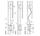
図1ないし図4の実施形態において、前突荷重を受けた場合のモデル変形について図11について説明する。車両が前突荷重を受けると、アッパレール14がロアレール13に対して前進し、荷重伝達ブラケット40がスクリューロッド20に対して前進する。すると、後方の荷重伝達壁41がナット部材48を介してスクリューロッド20を前方に押し、その結果、ワッシャ47が前方の荷重伝達壁41を押して該荷重伝達壁41を変形させる(スクリューロッド20の軸線に直交していた前方の荷重伝達壁41は下方が前に出る方向に変形する)。スクリューロッド20は荷重伝達壁41の挿通穴41aに挿通されているため、荷重伝達壁41のこの変形によって、スクリューロッド20は、挿通穴41aの図の下方の面(スクリューロッド20よりもアッパレール14の開口部側に位置する面)が変形支点(着力部)となって、その軸線後部が下方を向く方向に変形しようとする。しかし、スクリューロッド20の後部は後方の荷重伝達壁41の挿通穴41aに支持されているため、スクリューロッド20の後部は挿通穴41aの図の下方の面(スクリューロッド20よりもアッパレール14の開口部側に位置する面)が変形支点(着力部)となって再び上方に変形し、スクリューロッド20の変形(挫屈)方向が制限される。この変形の方向は、スクリューロッド20がアッパレール14(ロッド支持レール)の壁面と当接する方向であり、アッパレール14の摺動位置(シートSの前後方向位置)を問わず、一定の変形抑止効果が得られる。
In the embodiment shown in FIGS. 1 to 4, the model deformation in the case of receiving a front impact load will be described with reference to FIG. 11. When the vehicle receives a front collision load, the
図11のモデル変形を容易にするには、荷重伝達ブラケット40の一対の荷重伝達壁41の一方(送りナット16から遠い側の荷重伝達壁41)が他方(同近い側の荷重伝達壁41)より変形しやすいことが好ましい。このように、一対の荷重伝達壁41の一方を他方より変形容易にするための一つの手段は、一対の荷重伝達壁41に形成した支持突起41bとアッパレール14に穿設した固定穴14aとの嵌合クリアランスを異ならせることである。すなわち、図2において前方の固定穴14a(1)と支持突起41bとの前後方向のクリアランスを、後方の固定穴14a(2)と支持突起41bとの前後方向のクリアランスより大きく設定することで、一対の荷重伝達壁41の変形容易性を異ならせることができる。勿論、一対の荷重伝達壁41の幅や板厚を異ならせる等の手段で変形容易性を異ならせることもできる。
In order to facilitate the deformation of the model of FIG. 11, one of the pair of
図12は、一対の荷重伝達壁41の一方を他方より変形容易にするための別の構成例を示している。この実施形態では、一対の荷重伝達壁41のうち、送りナット16から遠い側の荷重伝達壁41には支持突起を設けず(アッパレール14には固定穴を設けず)、送りナット16に近い側の荷重伝達壁41には支持突起41aを設け、アッパレール14に固定穴14aを設けている。この態様によれば、支持突起41aが存在する側の荷重伝達壁41の変形強度を存在しない側の荷重伝達壁41の変形強度より明確に高くすることができる。
FIG. 12 shows another configuration example for making one of the pair of
本実施形態のパワースライド装置は、荷重伝達ブラケット40を送りナット16の後方に配置した態様(荷重伝達ブラケット40を送りナット16と軸受部材17との間に配置した態様)にも適用できる。この場合の荷重伝達ブラケット40の一対の荷重伝達壁41の変形容易性に対する議論は、送りナット16から遠い側の荷重伝達壁41の変形が近い側の荷重伝達壁41の変形より容易であるという条件を満足すればよい。また、本実施形態のパワースライド装置は、ロアレール13とアッパレール14の上下を入れ替える態様(ロアレール13にスクリューロッド20を回転自在に支持し、アッパレール14に送りナット16を固定する態様)、及び前後を反転する態様のいずれでも理論上成立するが、いずれの場合も以上の条件を満足すればよい。もっとも、本実施形態は、上述のように、荷重伝達ブラケット40が一対の荷重伝達壁41を有することでスクリューロッド20の挫屈の方向を限定できるという作用効果を有するものであり、図9のモデル変形の理論は一つの例である。
The power slide device of the present embodiment can also be applied to an aspect in which the
図5ないし図10は、本発明の別の実施形態を示している。
図5は、ギヤボックス30をアッパレール14に固定した実施形態である。荷重伝達ブラケット40は、ギヤボックス30の支持に関与していない。
5 to 10 show another embodiment of the present invention.
FIG. 5 shows an embodiment in which the
図6は、荷重伝達ブラケット40の一対の荷重伝達壁41の間に位置しスクリューロッド20のねじ部23に螺合固定される荷重受け部材として、単一のナット部材61を用いた実施形態である。この単一のナット部材61によれば、構成を単純にできる。
FIG. 6 shows an embodiment in which a
図7は、同荷重受け部材として、一対のナット部材62を用いた実施形態である。一対のナット部材62によれば、一対の荷重伝達部材41との寸法調整を容易に行うことができる。
FIG. 7 is an embodiment using a pair of
図8は、同荷重受け部材として、スクリューロッド20のねじ部23に螺合される単一のナット部材63であって、スクリューロッド20の小径段部22に係合する雌ねじを有しない小径段部63aを備えたナット部材を用いた実施形態である。このように小径段部63aを設けると、スクリューロッド20とナット部材63の軸受面積を拡大することができる。
FIG. 8 shows a
いずれの形態のナット部材であっても、スクリューロッド20への螺合前に、その雌ねじ部の内径を呼び径より小径に塑性変形させてスクリューロッドとの回転抵抗を増大させる緩み止め加工を施すことが望ましい。図9は、単一のナット部材64に、このような緩み止め加工を施す例を示している。ナット部材64には、同軸に、スクリューロッド20の小径段部22に係合する小径段部64aと、ねじ部23に螺合する雌ねじ64bが形成されている。このナット部材64に対し、軸方向から圧縮荷重Pを加えることで、雌ねじ64bに呼び径よりも小径な小径部分64cを形成する。このように小径部分64cを形成すると、スクリューロッド20に螺合させる際の回転抵抗を増大させることができ、該スクリューロッド20に螺合した後の特別なかしめ加工(固定手段)を省略することができる。
In any form of nut member, before screwing into the
図10は、スクリューロッドに、ねじ切り加工を施す前の丸棒素材20Sに対し、圧縮型200を介して、径方向に圧縮荷重Qを加える絞り加工を施す実施形態である。スクリューロッド20に対するねじ部23のねじ加工は、この絞り加工の後に施す。このように、丸棒素材20Sに絞り加工を施すと、スクリューロッド20の機械強度を増加させることができる。
FIG. 10 is an embodiment in which a drawing process for applying a compressive load Q in the radial direction is performed on the
S 車両用シート
F 床面
10 シートトラック
13 ロアレール
14 アッパレール
14a 締結穴
15 固定ボルト
16 送りナット
17 軸受部材
20 スクリューロッド
21 セレーション部
22 小径段部
23 ねじ部
30 ギヤボックス
31 接続ブラケット
31a 締結穴
32 ウォームホイル
32a セレーション穴
33 ウォーム
40 荷重伝達ブラケット
41 荷重伝達壁(荷重伝達部材)
41a 挿通穴
41b 支持突起
42 固定壁
43 固定ボルト
44 固定ナット
45 46 スリーブ
47 ワッシャ(荷重受け部材)
48 ナット部材(荷重受け部材)
50 ギヤボックス支持ブラケット
61 63 単一ナット部材(荷重受け部材)
62 一対のナット部材(荷重受け部材)
S Vehicle
48 Nut member (load receiving member)
50
62 A pair of nut members (load receiving members)
Claims (17)
このロアレールに摺動自在に係合しシート側に配設されるアッパレール;
上記アッパレールとロアレールのいずれか一方に回転自在に支持されたスクリューロッド;
該スクリューロッド支持レールの端部に設けられ、該スクリューロッドを回転駆動するギヤボックス;
上記スクリューロッドに螺合され、上記アッパレールとロアレールの他方に固定された送りナット;
上記スクリューロッド支持レールに、その延長方向に離間した位置で保持された一対の荷重伝達部材;及び
この一対の荷重伝達部材の間に位置させて上記スクリューロッドに軸方向位置を規制して設けた少なくとも一つの荷重受け部材;
を有し、
上記送りナット支持レールとスクリューロッド支持レールは互いに対向する開口部を備えていて、上記一対の荷重伝達部材は、上記スクリューロッドよりも、スクリューロッド支持レールの開口部側に位置する着力部を備えていることを特徴とする車両用シートのパワースライド装置。 A lower rail disposed on the vehicle floor;
An upper rail slidably engaged with the lower rail and disposed on the seat side;
A screw rod rotatably supported on one of the upper rail and the lower rail;
A gear box provided at an end portion of the screw rod support rail and for rotationally driving the screw rod;
A feed nut screwed to the screw rod and fixed to the other of the upper rail and the lower rail;
A pair of load transmission members held on the screw rod support rail at positions spaced apart in the extension direction; and a position in the axial direction of the screw rod that is positioned between the pair of load transmission members. At least one load bearing member;
Have
The feed nut support rail and the screw rod support rail are provided with openings facing each other, and the pair of load transmission members are provided with a force applying portion located on the opening side of the screw rod support rail with respect to the screw rod. A power slide device for a vehicle seat.
Priority Applications (5)
| Application Number | Priority Date | Filing Date | Title |
|---|---|---|---|
| JP2008164113A JP5291397B2 (en) | 2008-06-24 | 2008-06-24 | Power sliding device for vehicle seat |
| EP09770001.7A EP2298592B1 (en) | 2008-06-24 | 2009-06-05 | Power slide device for vehicle seat |
| US13/000,441 US8523263B2 (en) | 2008-06-24 | 2009-06-05 | Power slide device for vehicle seat |
| PCT/JP2009/060342 WO2009157291A1 (en) | 2008-06-24 | 2009-06-05 | Power slide device for vehicle seat |
| CN200980122715.1A CN102066151B (en) | 2008-06-24 | 2009-06-05 | Power slide device for vehicle seat |
Applications Claiming Priority (1)
| Application Number | Priority Date | Filing Date | Title |
|---|---|---|---|
| JP2008164113A JP5291397B2 (en) | 2008-06-24 | 2008-06-24 | Power sliding device for vehicle seat |
Publications (2)
| Publication Number | Publication Date |
|---|---|
| JP2010006098A true JP2010006098A (en) | 2010-01-14 |
| JP5291397B2 JP5291397B2 (en) | 2013-09-18 |
Family
ID=41444360
Family Applications (1)
| Application Number | Title | Priority Date | Filing Date |
|---|---|---|---|
| JP2008164113A Active JP5291397B2 (en) | 2008-06-24 | 2008-06-24 | Power sliding device for vehicle seat |
Country Status (5)
| Country | Link |
|---|---|
| US (1) | US8523263B2 (en) |
| EP (1) | EP2298592B1 (en) |
| JP (1) | JP5291397B2 (en) |
| CN (1) | CN102066151B (en) |
| WO (1) | WO2009157291A1 (en) |
Cited By (10)
| Publication number | Priority date | Publication date | Assignee | Title |
|---|---|---|---|---|
| JP2011173556A (en) * | 2010-02-25 | 2011-09-08 | Imasen Electric Ind Co Ltd | Seat rail device |
| JP2011195025A (en) * | 2010-03-19 | 2011-10-06 | Shiroki Corp | Method for manufacturing bar and screw bar |
| JP2011201371A (en) * | 2010-03-25 | 2011-10-13 | Shiroki Corp | Power seat truck |
| JP2011245902A (en) * | 2010-05-24 | 2011-12-08 | Shiroki Corp | Power sliding device |
| WO2012120670A1 (en) * | 2011-03-09 | 2012-09-13 | 株式会社日立製作所 | Linear actuator |
| KR101216147B1 (en) | 2010-12-30 | 2012-12-27 | 모터웰 주식회사 | Seat fixture |
| KR20130013360A (en) * | 2011-07-28 | 2013-02-06 | 주식회사다스 | Locking device for seat-rail of vehicle |
| JP2013173516A (en) * | 2012-01-24 | 2013-09-05 | Shiroki Corp | Power seat sliding apparatus |
| KR101407145B1 (en) * | 2012-10-31 | 2014-06-13 | 대동모벨시스템 주식회사 | Apparatus of driving car seat by sliding and gearbox used therein |
| WO2020036209A1 (en) * | 2018-08-17 | 2020-02-20 | テイ・エス テック株式会社 | Seat slide structure |
Families Citing this family (23)
| Publication number | Priority date | Publication date | Assignee | Title |
|---|---|---|---|---|
| JP5423261B2 (en) * | 2009-09-09 | 2014-02-19 | トヨタ車体株式会社 | Vehicle seat |
| FR2973747B1 (en) * | 2011-04-05 | 2013-05-03 | Faurecia Sieges Automobile | SPACER AND PROFILE FOR SEAT SLIDER OF MOTOR VEHICLE |
| DE102012107036B4 (en) | 2012-08-01 | 2021-08-26 | Dr. Ing. H.C. F. Porsche Aktiengesellschaft | Motor vehicle seat |
| JP5613744B2 (en) * | 2012-10-24 | 2014-10-29 | シロキ工業株式会社 | Slide rail device for vehicle |
| DE102012219629A1 (en) * | 2012-10-26 | 2014-04-30 | Robert Bosch Gmbh | Fulcrum shaft drive for adjustment device for adjusting seat in motor car, has torque-proof worm wheel connected with spindle, bolt retainer formed at thrust element, and bolt retainer aligned with another bolt retainer formed in housing |
| US10465836B2 (en) * | 2013-08-21 | 2019-11-05 | The Overly Hautz Motor Base Company | Motor mounting assembly and method of manufacture |
| DE102014201582A1 (en) * | 2014-01-29 | 2015-07-30 | Brose Fahrzeugteile Gmbh & Co. Kg, Coburg | Longitudinal adjustment for Längsverstellen a vehicle seat |
| JP6282560B2 (en) * | 2014-08-28 | 2018-02-21 | トヨタ紡織株式会社 | Vehicle seat slide rail |
| JP6284856B2 (en) | 2014-08-28 | 2018-02-28 | トヨタ紡織株式会社 | Vehicle seat slide rail |
| JP2017226356A (en) * | 2016-06-23 | 2017-12-28 | アイシン精機株式会社 | Vehicular seat slide device |
| JP2018016238A (en) * | 2016-07-29 | 2018-02-01 | アイシン精機株式会社 | Seat slide apparatus for vehicle |
| JP6756948B2 (en) * | 2016-09-26 | 2020-09-16 | デルタ工業株式会社 | Power seat slide device |
| DE102016219104A1 (en) * | 2016-09-30 | 2018-04-05 | Brose Fahrzeugteile Gmbh & Co. Kg, Coburg | Adjustment of a lumbar support or a Seitenwangenverstellers with spindle drive for a seat element of a vehicle seat |
| DE102016219105A1 (en) | 2016-09-30 | 2018-04-05 | Brose Fahrzeugteile Gmbh & Co. Kg, Coburg | Adjusting device with spindle drive for a seat element of a vehicle seat |
| DE102016224512A1 (en) * | 2016-12-08 | 2018-06-14 | Brose Fahrzeugteile Gmbh & Co. Kg, Coburg | Vehicle seat assembly with a floor rail side arranged drive means |
| US20180304777A1 (en) * | 2017-04-25 | 2018-10-25 | Toyota Boshoku Kabushiki Kaisha | Sliding device |
| CN110997402B (en) * | 2017-08-11 | 2022-07-12 | 恺博座椅机械部件有限公司 | Longitudinal adjuster for a vehicle seat |
| CN109080508B (en) * | 2018-08-28 | 2020-04-07 | 延锋安道拓座椅机械部件有限公司 | Motor directly links electronic slide rail of lead screw |
| WO2020082094A1 (en) * | 2018-10-19 | 2020-04-23 | Magna Seating Inc. | Removable seat used with a long rail assembly |
| JP7107823B2 (en) * | 2018-12-04 | 2022-07-27 | 株式会社Tf-Metal | Electric seat slide device |
| US11833933B2 (en) * | 2019-03-04 | 2023-12-05 | Adient Us Llc | Longitudinal adjusting device for the motorized longitudinal adjustment of a vehicle seat, and vehicle seat |
| US11530736B2 (en) * | 2019-06-26 | 2022-12-20 | Ford Global Technologies, Llc | Support mechanism for a track system |
| JP7319142B2 (en) * | 2019-08-28 | 2023-08-01 | 株式会社Tf-Metal | Electric seat slide device |
Citations (5)
| Publication number | Priority date | Publication date | Assignee | Title |
|---|---|---|---|---|
| JPH11123960A (en) * | 1997-10-22 | 1999-05-11 | Delta Kogyo Co Ltd | Power seat for vehicle |
| JP2004352081A (en) * | 2003-05-29 | 2004-12-16 | Shiroki Corp | Power seat slide device |
| JP2007001508A (en) * | 2005-06-27 | 2007-01-11 | Aisin Seiki Co Ltd | Seat slide device for vehicle |
| JP2007050715A (en) * | 2005-08-15 | 2007-03-01 | Imasen Electric Ind Co Ltd | Slide rail of power seat |
| JP2007126103A (en) * | 2005-11-07 | 2007-05-24 | Aisin Seiki Co Ltd | Power seat sliding device for vehicle |
Family Cites Families (6)
| Publication number | Priority date | Publication date | Assignee | Title |
|---|---|---|---|---|
| US5456439A (en) | 1993-12-15 | 1995-10-10 | Itt Corporation | Vehicle power seat adjuster with self-aligning lead screw actuator |
| EP1331131B1 (en) * | 2002-01-23 | 2007-09-26 | Delta Kogyo Co., Ltd. | A power seat for a vehicle |
| FR2837148B1 (en) * | 2002-03-18 | 2004-07-02 | Faurecia Sieges Automobile | ADJUSTING MECHANISM FOR A MOTOR VEHICLE SEAT SLIDER AND SLIDER AND SEAT EQUIPPED WITH SUCH A MECHANISM |
| JP5055918B2 (en) | 2006-09-28 | 2012-10-24 | アイシン精機株式会社 | Power seat slide device |
| US20080079908A1 (en) * | 2006-10-02 | 2008-04-03 | Hae-Yong Choi | Visual advertising apparatus for gateway |
| US7887020B2 (en) * | 2007-03-26 | 2011-02-15 | Ami Industries, Inc. | Seat track locking mechanism |
-
2008
- 2008-06-24 JP JP2008164113A patent/JP5291397B2/en active Active
-
2009
- 2009-06-05 CN CN200980122715.1A patent/CN102066151B/en not_active Expired - Fee Related
- 2009-06-05 EP EP09770001.7A patent/EP2298592B1/en not_active Not-in-force
- 2009-06-05 WO PCT/JP2009/060342 patent/WO2009157291A1/en active Application Filing
- 2009-06-05 US US13/000,441 patent/US8523263B2/en active Active
Patent Citations (5)
| Publication number | Priority date | Publication date | Assignee | Title |
|---|---|---|---|---|
| JPH11123960A (en) * | 1997-10-22 | 1999-05-11 | Delta Kogyo Co Ltd | Power seat for vehicle |
| JP2004352081A (en) * | 2003-05-29 | 2004-12-16 | Shiroki Corp | Power seat slide device |
| JP2007001508A (en) * | 2005-06-27 | 2007-01-11 | Aisin Seiki Co Ltd | Seat slide device for vehicle |
| JP2007050715A (en) * | 2005-08-15 | 2007-03-01 | Imasen Electric Ind Co Ltd | Slide rail of power seat |
| JP2007126103A (en) * | 2005-11-07 | 2007-05-24 | Aisin Seiki Co Ltd | Power seat sliding device for vehicle |
Cited By (15)
| Publication number | Priority date | Publication date | Assignee | Title |
|---|---|---|---|---|
| JP2011173556A (en) * | 2010-02-25 | 2011-09-08 | Imasen Electric Ind Co Ltd | Seat rail device |
| JP2011195025A (en) * | 2010-03-19 | 2011-10-06 | Shiroki Corp | Method for manufacturing bar and screw bar |
| JP2011201371A (en) * | 2010-03-25 | 2011-10-13 | Shiroki Corp | Power seat truck |
| US8733725B2 (en) | 2010-05-24 | 2014-05-27 | Shiroki Corporation | Power slider |
| JP2011245902A (en) * | 2010-05-24 | 2011-12-08 | Shiroki Corp | Power sliding device |
| KR101216147B1 (en) | 2010-12-30 | 2012-12-27 | 모터웰 주식회사 | Seat fixture |
| WO2012120670A1 (en) * | 2011-03-09 | 2012-09-13 | 株式会社日立製作所 | Linear actuator |
| JP5535396B2 (en) * | 2011-03-09 | 2014-07-02 | 株式会社日立製作所 | Linear actuator |
| KR20130013360A (en) * | 2011-07-28 | 2013-02-06 | 주식회사다스 | Locking device for seat-rail of vehicle |
| KR101670094B1 (en) | 2011-07-28 | 2016-11-10 | 주식회사다스 | Locking device for seat-rail of vehicle |
| JP2013173516A (en) * | 2012-01-24 | 2013-09-05 | Shiroki Corp | Power seat sliding apparatus |
| US9511685B2 (en) | 2012-01-24 | 2016-12-06 | Shiroki Corporation | Power seat sliding apparatus |
| KR101407145B1 (en) * | 2012-10-31 | 2014-06-13 | 대동모벨시스템 주식회사 | Apparatus of driving car seat by sliding and gearbox used therein |
| WO2020036209A1 (en) * | 2018-08-17 | 2020-02-20 | テイ・エス テック株式会社 | Seat slide structure |
| US10906429B2 (en) | 2018-08-17 | 2021-02-02 | Ts Tech Co., Ltd. | Seat slide structure |
Also Published As
| Publication number | Publication date |
|---|---|
| US8523263B2 (en) | 2013-09-03 |
| CN102066151A (en) | 2011-05-18 |
| EP2298592A1 (en) | 2011-03-23 |
| EP2298592B1 (en) | 2015-04-08 |
| WO2009157291A1 (en) | 2009-12-30 |
| CN102066151B (en) | 2013-05-01 |
| US20110095160A1 (en) | 2011-04-28 |
| JP5291397B2 (en) | 2013-09-18 |
| EP2298592A4 (en) | 2012-07-04 |
Similar Documents
| Publication | Publication Date | Title |
|---|---|---|
| JP5291397B2 (en) | Power sliding device for vehicle seat | |
| JP4696864B2 (en) | Seat slide device | |
| JP2008080997A (en) | Power seat sliding device | |
| KR101501384B1 (en) | Gear box for seat sliding device in vehicle | |
| EP2253501B1 (en) | Screw configuration of seat apparatus for vehicle | |
| JP2009255890A (en) | Feeding device | |
| JP2006298271A (en) | Power seat sliding device for vehicle | |
| JP2010064677A (en) | Vehicular power seat device | |
| JP2020019327A (en) | Steering device | |
| KR20090092951A (en) | A gear box of seat sliding device for a car | |
| JP4774867B2 (en) | Power seat slide device | |
| JP4831302B2 (en) | Power seat slide device for vehicle | |
| JP5063972B2 (en) | Power slide seat for vehicles | |
| JP5531083B2 (en) | Power sliding device for vehicle seat | |
| JP5134906B2 (en) | Upper rail connecting device in power slide device for vehicle seat | |
| JP2008155783A (en) | Electric seat slide device | |
| JP5796386B2 (en) | Vehicle seat device | |
| JP5476453B2 (en) | Power sliding device for vehicle seat | |
| JP2009090799A (en) | Power slide device for vehicular seat | |
| JP5361281B2 (en) | Power sliding device for vehicle seat | |
| JP2005096522A (en) | Seat slide device | |
| JP2013079074A (en) | Power slide device of vehicle seat | |
| JP2007210504A (en) | Power seat slide device | |
| JP5184039B2 (en) | Power sliding device for vehicle seat | |
| JP2009090800A (en) | Power slide device for vehicular seat |
Legal Events
| Date | Code | Title | Description |
|---|---|---|---|
| A621 | Written request for application examination |
Free format text: JAPANESE INTERMEDIATE CODE: A621 Effective date: 20110615 |
|
| A131 | Notification of reasons for refusal |
Free format text: JAPANESE INTERMEDIATE CODE: A131 Effective date: 20130305 |
|
| A521 | Request for written amendment filed |
Free format text: JAPANESE INTERMEDIATE CODE: A523 Effective date: 20130417 |
|
| TRDD | Decision of grant or rejection written | ||
| A01 | Written decision to grant a patent or to grant a registration (utility model) |
Free format text: JAPANESE INTERMEDIATE CODE: A01 Effective date: 20130604 |
|
| A61 | First payment of annual fees (during grant procedure) |
Free format text: JAPANESE INTERMEDIATE CODE: A61 Effective date: 20130607 |
|
| R150 | Certificate of patent or registration of utility model |
Ref document number: 5291397 Country of ref document: JP Free format text: JAPANESE INTERMEDIATE CODE: R150 |
|
| R250 | Receipt of annual fees |
Free format text: JAPANESE INTERMEDIATE CODE: R250 |
|
| R250 | Receipt of annual fees |
Free format text: JAPANESE INTERMEDIATE CODE: R250 |
|
| S111 | Request for change of ownership or part of ownership |
Free format text: JAPANESE INTERMEDIATE CODE: R313113 |
|
| R350 | Written notification of registration of transfer |
Free format text: JAPANESE INTERMEDIATE CODE: R350 |