JP2010005753A - Tweezers for holding calibration weight - Google Patents
Tweezers for holding calibration weight Download PDFInfo
- Publication number
- JP2010005753A JP2010005753A JP2008168867A JP2008168867A JP2010005753A JP 2010005753 A JP2010005753 A JP 2010005753A JP 2008168867 A JP2008168867 A JP 2008168867A JP 2008168867 A JP2008168867 A JP 2008168867A JP 2010005753 A JP2010005753 A JP 2010005753A
- Authority
- JP
- Japan
- Prior art keywords
- holding
- tweezers
- fulcrum
- calibration weight
- gripping
- Prior art date
- Legal status (The legal status is an assumption and is not a legal conclusion. Google has not performed a legal analysis and makes no representation as to the accuracy of the status listed.)
- Granted
Links
- 239000000463 material Substances 0.000 claims abstract description 39
- 229910052751 metal Inorganic materials 0.000 claims abstract description 34
- 239000002184 metal Substances 0.000 claims abstract description 34
- 229920003051 synthetic elastomer Polymers 0.000 claims abstract description 13
- 229920003002 synthetic resin Polymers 0.000 claims abstract description 13
- 239000000057 synthetic resin Substances 0.000 claims abstract description 13
- 239000005061 synthetic rubber Substances 0.000 claims abstract description 13
- 238000000926 separation method Methods 0.000 claims description 2
- 210000003811 finger Anatomy 0.000 description 13
- 230000006866 deterioration Effects 0.000 description 6
- 238000005303 weighing Methods 0.000 description 6
- 230000001133 acceleration Effects 0.000 description 5
- 210000004932 little finger Anatomy 0.000 description 5
- 229920005989 resin Polymers 0.000 description 4
- 239000011347 resin Substances 0.000 description 4
- 230000005484 gravity Effects 0.000 description 3
- 238000005259 measurement Methods 0.000 description 3
- 230000002265 prevention Effects 0.000 description 3
- 210000003813 thumb Anatomy 0.000 description 3
- 230000036760 body temperature Effects 0.000 description 2
- 230000000694 effects Effects 0.000 description 2
- 229920001971 elastomer Polymers 0.000 description 2
- 230000005611 electricity Effects 0.000 description 2
- 210000004247 hand Anatomy 0.000 description 2
- 239000005060 rubber Substances 0.000 description 2
- 229910001220 stainless steel Inorganic materials 0.000 description 2
- 239000010935 stainless steel Substances 0.000 description 2
- 230000003068 static effect Effects 0.000 description 2
- 241000282412 Homo Species 0.000 description 1
- 210000001015 abdomen Anatomy 0.000 description 1
- 230000000903 blocking effect Effects 0.000 description 1
- 238000011109 contamination Methods 0.000 description 1
- 230000007423 decrease Effects 0.000 description 1
- 238000010586 diagram Methods 0.000 description 1
- 238000006073 displacement reaction Methods 0.000 description 1
- 229910001385 heavy metal Inorganic materials 0.000 description 1
- 238000001746 injection moulding Methods 0.000 description 1
- 230000005389 magnetism Effects 0.000 description 1
- 238000004519 manufacturing process Methods 0.000 description 1
- 230000001012 protector Effects 0.000 description 1
- 230000003252 repetitive effect Effects 0.000 description 1
- 239000002904 solvent Substances 0.000 description 1
- 239000013585 weight reducing agent Substances 0.000 description 1
- 238000003466 welding Methods 0.000 description 1
Images


Abstract
Description
この発明は、校正分銅把持用ピンセットに関し、特に、広範囲にわたる重さがある校正用分銅の把持に適したピンセットに関するものである。 The present invention relates to tweezers for holding a calibration weight, and more particularly to tweezers suitable for holding a calibration weight having a wide range of weights.
天びん・はかりでは、質量を直接測定できないので、天びん・はかりを設置した各地或において、または、各機種毎に重力補正を行う必要がある。この重力補正とは、国際標準となるフランスにある1kg原器をベースとして、トレーサブルな各分銅が作られ、それらの分銅を使い、その場所での重力加速度は、一定との仮定から、分銅質量 ×重力加速度を力として計量器に加え、その力により発生する質量センサの変位または変位をゼロに戻す為に必要となる電気力により換算し、被測定物の質量を確定(推定)している。 Since the balance and scale cannot directly measure the mass, it is necessary to perform gravity correction at each location where the balance or scale is installed or for each model. This gravity correction is based on the assumption that the weight acceleration is constant at the place where traceable weights are made based on the international standard 1kg prototype in France. X Gravity acceleration is applied as a force to the measuring instrument, and the mass sensor displacement generated by the force is converted by the electric force required to return to zero, and the mass of the object to be measured is determined (estimated). .
例えば、日本国内でも主に緯度の違いから、重力加速度の最大差は、約1/1000(0.1%)もあり、ひょう量と最小表示量との差が、1000倍以上ある計量器では大きな計量誤差となってあらわれる。 For example, in Japan, mainly due to the difference in latitude, the maximum difference in gravitational acceleration is about 1/1000 (0.1%), and for measuring instruments where the difference between the weighing capacity and the minimum display amount is 1000 times or more Appears as a large weighing error.
より具体的には、ひょう量200g×最小表示0.1mgとなる分析天びんでは、同じ200gの試料を測定しても、重力加速度差は、200g×1/1000=0.2gとなり、最小表示の2000倍の誤差となって計量される。重力加速度以外でも、温度、気圧、湿度の変化により計量値の変化が発生するため、分銅による校正は、必然となっている。 More specifically, in an analytical balance having a weighing capacity of 200 g × minimum display of 0.1 mg, even if the same 200 g sample is measured, the gravitational acceleration difference is 200 g × 1/1000 = 0.2 g, which is the minimum display. It is measured with an error of 2000 times. In addition to gravitational acceleration, changes in measured values occur due to changes in temperature, pressure, and humidity, so calibration with a weight is inevitable.
分銅による計量器の校正作業では、分銅の汚染を防ぎ傷つけない、分銅に体温を伝えない、ひょう量室に体温による熱対流を起こさない、磁気や静電気を帯びない、把持治具 となるピンセットの操作が確実かつ容易で、繰り返し操作により人が疲れず、分銅の落下などを起こさずに安全にかつ正確に行えるなどの要求があり、これらのすべてを解決できる専用ピンセットは、現在まで提供されていない。 The calibration of the weighing instrument with weights prevents contamination of the weights and does not damage them, does not transmit body temperature to the weights, does not cause thermal convection due to body temperature in the weighing chamber, does not carry magnetism or static electricity, and does not have magnetic or static electricity. There is a demand for reliable and easy operation, repetitive operation that does not make people tired, and safe and accurate operation without causing weight drop, etc. Absent.
特に、校正分銅用ピンセットの場合、200g程度の分銅を把持することが多く、最大では、500g〜1kgまで、最小では、1〜2gまでの 分銅を使用する場合がある。 In particular, in the case of tweezers for calibration weight, a weight of about 200 g is often gripped, and a weight of 500 g to 1 kg at the maximum and 1 to 2 g at the minimum may be used.
この範囲の最大重量は、市販されている通常のピンセットで想定される把持重量を大幅に超えており、専用設計が必要となることは容易に推測される。
従来から校正分銅の把持に用いられていたピンセットには、通常の金属製ピンセットを利用し、先端把持部に樹脂製プロテクタを配置した構造(特許文献1参照)や合成樹脂でピンセット本体を構成して専用化した構造が提供されている。しかしながら、このような従来のピンセットには、以下に説明する課題があった。
The maximum weight in this range greatly exceeds the gripping weight assumed for ordinary tweezers on the market, and it is easily assumed that a dedicated design is required.
Conventional tweezers that have been used for gripping calibration weights use ordinary metal tweezers, and have a tweezers body made up of a structure (see Patent Document 1) in which a resin protector is placed on the tip gripping part. Dedicated structures are provided. However, such conventional tweezers have the following problems.
すなわち、通常のピンセットが小さな物を掴むことを目的としているのに対し、分銅用ピンセットは、重い金属製分銅を掴むことを目的としており、親指,人差し指,中指で1点を握る通常のピンセット操作と異なり、構成分銅の把持に用いるピンセットでは、分銅を操作する時、機能的には、作用点となる分銅を掴む部分、指で挟みこむ力点部、及び、ピンセット操作時の固定点となる小指で把持する支点部が必要となる。 In other words, normal tweezers are intended to grab a small object, whereas weight tweezers are intended to grasp heavy metal weights, and the usual tweezers operation is to hold one point with the thumb, index finger, and middle finger. Unlike tweezers used for gripping the weight of a component, functionally, when operating the weight, the part that grips the weight that acts as the action point, the force point that is pinched by the finger, and the little finger that is the fixed point when tweezers is operated A fulcrum part to be gripped with is required.
ところが、前者の構造では、金属製のピンセットは、重量軽減の必要性から素材が薄く、特に、重い分銅を掴んだ時に、支点部で手と小指への負担が大きくなるという問題があり、また、力点部の指に十分な力を加えることができるような構造になっていなかった。 However, in the former structure, the metal tweezers are thin due to the need for weight reduction, and there is a problem that the burden on the hand and little finger is increased at the fulcrum part, especially when a heavy weight is grasped. The structure was such that a sufficient force could be applied to the finger at the power point.
また、後者の構造では、樹脂製ピンセットは、小型のものが多く、特に、重い分銅用のものは、剛性を必要とすることと、射出成形の生産技術的背景と重さの制限から肉厚は、上限があって厚くできないことから、結果的に形状により剛性を持たせるためのリブ構造となり かなりの容積を有するものとなっている。しかし、容積の大きいものは、天びん・はかりの風防内においた分銅を掴む場合など、細かい作業を行う際の操作性が悪いという問題があった。 In the latter structure, many of the tweezers made of resin are small, especially those for heavy weights, which require rigidity and are thick due to the production technical background of the injection molding and weight limitations. Since there is an upper limit and the thickness cannot be increased, the result is a rib structure for providing rigidity depending on the shape, and has a considerable volume. However, the large volume has a problem that the operability when performing fine work is poor, such as when holding a weight in the windshield of a balance / balance.
本発明は、このような従来の問題点に鑑みてなされたものであって、その目的とするところは、重い分銅を掴んだ場合にも支点部での負担が小さく、力点部に十分な力を加えることが可能で、かつ、天びん、はかりに設定された風防内で細かい作業を行う際の操作性の悪化を回避することができ、また、人体からの熱伝導を軽減できる樹脂材料により手とピンセットの金属部を遮断できる校正分銅把持用ピンセットを提供することにある。 The present invention has been made in view of such conventional problems. The object of the present invention is to reduce the burden on the fulcrum portion even when a heavy weight is gripped, and to provide sufficient force on the force point portion. It is possible to avoid deterioration of operability when performing fine work in the draft shield set on the balance and balance, and to reduce the heat conduction from the human body. Another object of the present invention is to provide tweezers for holding a calibration weight capable of blocking the metal part of the tweezers.
上記目的を達成するために、本発明は、2枚の平板状金属板を対面配置して、基端側で相互に接合固定した支点部を有し、当該支点部の厚みを他の部分よりも薄くし、先端側に上下に離間する校正用分銅の把持部を設けるとともに、前記支点部と前記把持部との間に把持力発生部を設け、前記把持力発生部への加力により、前記平板状金属板を相互に近接移動させて、前記把持部で校正用分銅を掴むことができるピンセットであって、前記支点部は、前記金属板の基端側に形成された同一幅の領域であり、前記把持力発生部は、前記金属板の概略中央部に形成された最大幅の領域であり、前記把持部は、前記金属板の先端側に形成された先細状の領域からなり、前記支点部は、合成樹脂やゴムで形成した柔軟なサポート材で被覆され、前記把持力発生部は、合成樹脂やゴムで形成した滑り防止用のグリップ材で被覆され、前記把持部は、前記校正用分銅との摩擦力を維持し、熱伝導防止用のキャップで被覆するようにした。 In order to achieve the above-mentioned object, the present invention has a fulcrum part in which two flat metal plates are arranged facing each other and bonded and fixed to each other on the base end side, and the thickness of the fulcrum part is set to be different from that of other parts. And a gripping portion for the calibration weight that is vertically spaced apart on the tip side, and a gripping force generating portion is provided between the fulcrum portion and the gripping portion, and by applying force to the gripping force generating portion, The tweezers can move the flat metal plates close to each other and grip the calibration weight with the gripping portion, and the fulcrum portion is a region of the same width formed on the base end side of the metal plate The gripping force generating portion is a region having a maximum width formed at a substantially central portion of the metal plate, and the gripping portion is formed by a tapered region formed on the tip side of the metal plate, The fulcrum portion is covered with a flexible support material formed of synthetic resin or rubber, and the grip The force generation part is covered with a grip material for preventing slip formed of synthetic resin or rubber, and the grip part maintains a frictional force with the calibration weight and is covered with a cap for preventing heat conduction. did.
このように構成した校正分銅把持用ピンセットによれば、2枚の平板状金属板を対面配置して、基端側で相互に接合固定した支点部を有しているので、十分な剛性を確保することができ、また、支点部は、合成樹脂やゴムで形成した柔軟なサポート材で被覆されているので、小指と手のひらで支点部を掴んだときに、手指の負担が緩和され、確実な支点としての機能を発揮させることができる。 According to the calibration weight grasping tweezers configured in this way, two flat metal plates are arranged facing each other and have a fulcrum part that is bonded and fixed to each other on the base end side, so that sufficient rigidity is secured. Also, since the fulcrum part is covered with a flexible support material made of synthetic resin or rubber, when the fulcrum part is grasped by the little finger and palm, the burden on the finger is alleviated and reliable. The function as a fulcrum can be demonstrated.
また、把持力発生部は、金属板の概略中央部に形成された最大幅の領域で、かつ、合成樹脂やゴムで形成した滑り防止用のグリップ材で被覆されているので、力点部に十分な力を加えることができる。 In addition, the gripping force generation part is the maximum width area formed at the approximate center of the metal plate and is covered with a slip-preventing grip material made of synthetic resin or rubber. Can be applied.
さらに、把持部は、金属板の先端側に形成された先細状の領域からなり、かつ、校正用分銅との摩擦力を維持し、熱伝導防止用のキャップで被覆するので、校正分銅に熱を伝達することなく、風防により形成されたひょう量室内で熱により発生する空気の対流による計量誤差を減少させると同時に、細かい作業を行う際の操作性の悪化を回避することができる。 Furthermore, the gripping portion is formed of a tapered region formed on the front end side of the metal plate, maintains the frictional force with the calibration weight, and is covered with a cap for preventing heat conduction. Therefore, it is possible to reduce the measurement error due to the convection of air generated by heat in the weighing chamber formed by the windshield, and at the same time, avoid the deterioration of operability when performing fine work.
前記金属板の先端側には、前記キャップの脱落防止用の段差部を設けることができる。この構成によれば、キャップの脱落防止と、交換時の容易性とを確保することができる。
前記キャップは、前記校正用分銅の把持側内面に凸部を設けることができる。この構成によれば、1g程度の軽い分銅も容易に把持することができる。
A stepped portion for preventing the cap from falling off may be provided on the tip side of the metal plate. According to this configuration, it is possible to ensure cap prevention and ease of replacement.
The cap can be provided with a protrusion on the inner surface of the calibration weight on the grip side. According to this configuration, a light weight of about 1 g can be easily grasped.
前記グリップ材は、その表面に指の挿入が可能な凹部を形成することができる。この構成によれば、より一層安定した状態で、かつ、容易に力点に加力することができる。 The grip material can be formed with a recess on the surface where a finger can be inserted. According to this configuration, it is possible to apply force to the power point easily in a more stable state.
前記グリップ材は、前記サポート材と一体化され、一体化されたグリップ材を前記支点部の後端側から、前記把持力発生部まで覆うように装着することができる。 The grip material is integrated with the support material, and can be mounted so as to cover the integrated grip material from the rear end side of the fulcrum portion to the grip force generation portion.
前記サポート材と一体化されたグリップ材は、その内面側の幅方向の両端に離脱防止用の複数の突起を設けることができる。 The grip material integrated with the support material can be provided with a plurality of protrusions for preventing separation at both ends in the width direction on the inner surface side.
本発明にかかる校正分銅把持用ピンセットによれば、重い分銅を掴んだ場合にも支点部での負担が小さく、力点部に十分な力を加えることが可能で、かつ、細かい作業を行う際の操作性の悪化を回避することができる。 According to the tweezers for gripping a calibration weight according to the present invention, even when a heavy weight is gripped, the burden on the fulcrum portion is small, it is possible to apply a sufficient force to the force point portion, and when performing fine work Deterioration of operability can be avoided.
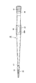
以下、本発明の好適な実施の形態について、添付図面に基づいて詳細に説明する。図1から図3は、本発明に係る校正分銅把持用ピンセットの一実施例を示している。 DESCRIPTION OF EXEMPLARY EMBODIMENTS Hereinafter, preferred embodiments of the invention will be described in detail with reference to the accompanying drawings. 1 to 3 show an embodiment of a tweezer for grasping a calibration weight according to the present invention.
これらの図に示した校正分銅把持用ピンセット10は、厚みが数mm、例えば、2mm程度の平板状のステンレス金属板を対面配置した構造になっている。2枚の金属板は、基端側で相互に溶接などにより接合固定した支点部12となっている。本実施例の場合、支点部12は、他の部分よりも薄くしている。
The calibration
そして、先端側には、上下方向に所定の間隔で離間する校正用分銅の把持部14が設けられている。また、支点部12と把持部14との間には、校正用分銅Aを把持する際に、親指と人差し指とを上下から当接して、金属板同士が近接するように力を加える把持力発生部16が設けられている。
On the distal end side, a calibration
このように構成したピンセット10では、図4に示すように、把持部14の間に校正用分銅を位置させて、把持発生部16に加力して、金属板を相互に近接する方向に移動させると、把持部14で校正用分銅を掴むことができる。
In the
この場合、支点部12は、平板状金属板の基端側に設けられた、同一幅、例えば、10mm程度の幅の領域である。また、把持部14は、平板状金属板の先端側に設けられた領域であり、先端側に向けて漸次幅が縮小する先細状に形成されている。把持力発生部16は、平板状金属板の概略中央部分に形成され、最大幅、例えば、13mm程度の幅を有している。
In this case, the
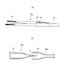
そして、金属板の先端側には、側面の一部を対向する個所で切欠する形態の段差部17が設けられている。この段差部17の先端側の領域が把持部14となっている。
And the level | step-
支点部12は、合成樹脂やゴムで形成した柔軟なサポート材18で覆われている。また、把持部14は、校正用分銅Aとの摩擦力を維持し、熱伝導防止用の一対のキャプ20でそれぞれ覆われている。このキッャプ20は、合成樹脂やゴムなどで形成され、その後端側は、段差部17の内部に入り込んでいる。
The
本実施例の場合、キャップ20には、図3にその詳細を示すように、校正用分銅Aの把持側内面に位置するようにして、凸部20aが設けられている。なお、図4に示した例では、凸部20aは、キッャプ20の内外面に設けられているが、内面側にだけ設けたものでもよい。
In the case of the present embodiment, the
さらに、把持力発生部16には、合成樹脂やゴムで形成した滑り防止用のグリップ22で被覆されている。本実施例の場合、このグリップ22の表面側の中央には、指の腹や先端を挿入することができる凹部22aが設けられている。
Further, the gripping
以上のように構成した天びん・はかり用の校正分銅把持用ピンセット10では、約1kgまでの校正用分銅Aを操作することができる比較的全長の長い金属製ピンセットである。
The balance /
また、以上のように構成されたピンセット10によれば、以下の作用効果が奏される。厚みが数mm以上の2枚の平板状金属板を対面配置して、基端側で相互に接合固定した支点部12を有しているので、十分な剛性を確保することができ、また、支点部12は、合成樹脂やゴムで形成した柔軟なサポート材18で被覆されているので、小指と手のひらで支点部12を掴んだときに、手指の負担が緩和され、確実な支点としての機能を発揮させることができる。
Moreover, according to the
また、把持力発生部16は、金属板の概略中央部に形成された最大幅の領域で、かつ、合成樹脂やゴムで形成した滑り防止用のグリップ材22で被覆されているので、力点部に十分な力を加えることができる。
In addition, the gripping
さらに、把持部14は、金属板の先端側に形成された先細状の領域からなり、かつ、校正用分銅Aとの摩擦力を維持し、熱伝導防止用のキャップ20で被覆するので、校正用分銅Aに熱を伝達することなく、細かい作業を行う際の操作性の悪化を回避することができる。
Furthermore, the gripping
また、このようなピンセット10は、サポート材18,キャップ20,グリップ22を有しているので、 例えば、計量管理担当者が一日中繰り返し計量器の校正作業を行う時でも、指及び手への負担を低減し、同時に確実な分銅把持操作性が確保されるとともに、校正時の誤差となる校正用分銅Aへの手からの伝熱、および、風防内での人体の熱による対流の軽減が達成される。
In addition, since the
さらに、ピンセット10の支点部12には、樹脂やゴムなどの材料を利用したサポート材18を設けて、これを幅広とし、小指、薬指及びそれらの持と対面する手のひら部分で掴んだ時に持と手への負担を軽減しているとともに、これと同時に、確実な支点としての機能を発揮し分銅換作の安全性を高めている。
Further, the
またさらに、主に親指と人指し指で挟み込む把持力発生部16(力点部)をピンセット10の他の部分よりも最も幅広な領域とすることで、重い校正用分銅Aを掴んだ場合にも、支点部12での負担が小さく、力点部に十分な力を加えることが可能で、かつ、細かい作業を行う際の操作性の悪化を回避することができる。
Furthermore, the gripping force generating portion 16 (power point portion) that is mainly sandwiched between the thumb and the index finger is made the widest region than the other portions of the
また、把持力発生部16は、ピンセット10の他の部分より幅広としグリップし易い形状とし、その一方で、幅を変えることで把持する部分を明確に視認できるようにしている。
The gripping
このキャップ20は、ピンセット10と分銅A間の緩衝材となるため、繰り返し使用により疲弊し、また脱落しやすい条件で使われる。 そこで、キャップ20の脱落防止と取替えを容易にするための段差部17をピンセット10の先端部分に設けている。
Since the
本実施例の場合、キャップ20の材料には、ゴムなど摩際係数の比較的大きく、同時に、天びんを汚染する溶剤などが溶出しない素材を利用し、分銅A側となる内面には比較的軽く小さい分銅の首を把持できるような凸部20aが設けられている。この凸部20aは、図4に示すように機能する、図4では、左側が約1kgの最も重い校正用分銅A1であり、右側が2g程度の軽い校正用分銅A2を把持した例である。
In the case of the present embodiment, the
キャップ20に凸部20aを設けた場合には、重く大きい校正用分銅A1では、首部の内径が大きいので、凸部20aを含むキャップ20の全体が首部内に入り込んで、その内面に当接する。一方、軽い校正用分銅A2では、首部内にキャップ20の全体を入り込ませることはできないが、凸部20aが侵入して、その内面に当接させることができ、これにより幅広い重量の校正用分銅の把持が可能になっている。
When the
さらにまた、本実施例の場合には、グリップ材22には、その表面に指の挿入が可能な凹状部22aが形成されており、この構成により、より一層安定した状態で、かつ、容易に力点に加力することができる。
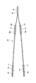
図5は、本発明に係る校正分銅把持用ピンセットの他の実施例を示しており、上記実施例と同一もしくは相当する部分に同一符号を付してその説明を省略するとともに、以下にその特徴点についてのみ説明する。
Furthermore, in the case of the present embodiment, the
FIG. 5 shows another embodiment of the calibration weight gripping tweezers according to the present invention. The same or corresponding parts as those in the above embodiment are designated by the same reference numerals and the description thereof is omitted. Only the point will be described.
同図に示したピンセット10aは、上記実施例と同様に、2枚の平板状金属板を対面配置して、基端側で相互に接合固定した支点部12を有し、先端側に把持部14を設け、支点部12と把持部14との間に把持力発生部16を設けている。
The
本実施例の場合、把持部14には、キャップ20が装着され、把持力発生部16を覆うグリップ材220は、上記実施例で示した支点部12を覆うサポート材と一体化されている。
In the case of this embodiment, the
一体化されたグリップ材220は、所定の幅を有する二又状に分岐した形状を有し、基端側は、袋状になっており、かつ、分岐した一対の先端側には、幅方向の端部に複数の突起221が、所定の間隔を隔てて、対向するように設けられている。
The
このような形状のグリップ材220は、図5(B)に示すように、支点部12の後端側から、支点部12が内部に挿入され、先端側が把持力発生部16を覆うように装着する。
As shown in FIG. 5B, the
このようにしてサポート材と一体化されたグリップ材220は、装着されると、突起221間に把持力発生部16の幅方向端部が当接して、グリップ材220の離脱を防止するようになっている。以上のように構成された校正分銅把持用ピンセット10aによっても上記実施例と同等の作用効果が得られる。
When the
本発明にかかる校正分銅把持用ピンセットによれば、重い分銅を掴んだ場合にも支点部での負担が小さく、力点部に十分な力を加えることが可能で、かつ、細かい作業を行う際の操作性の悪化を回避することができ、また、主としてステンレスで構成される分銅に対して、同一材料で構成されるピンセットで、主に人が触る表面を樹脂で覆うことで、熱伝導を軽減し、分銅の温度上昇による熱対流を減じ、正確な校正作業を実現し、重量計測の分野で有効に活用することができる。 According to the tweezers for gripping a calibration weight according to the present invention, even when a heavy weight is gripped, the burden on the fulcrum portion is small, it is possible to apply a sufficient force to the force point portion, and when performing fine work Deterioration of operability can be avoided, and heat conduction is reduced by covering the surface that humans mainly touch with resin with tweezers made of the same material for weights made mainly of stainless steel. In addition, it reduces heat convection due to the temperature rise of the weight, realizes accurate calibration work, and can be used effectively in the field of weight measurement.
10 ピンセット
12 支点部
14 把持部
16 把持力発生部
18 サポート材
20 キャップ
22 グリップ
10
Claims (6)
前記支点部は、前記金属板の基端側に形成された同一幅の領域であり、
前記把持力発生部は、前記金属板の概略中央部に形成された最大幅の領域であり、前記把持部は、前記金属板の先端側に形成された先細状の領域からなり、
前記支点部は、合成樹脂やゴムで形成した柔軟なサポート材で被覆され、
前記把持力発生部は、合成樹脂やゴムで形成した滑り防止用のグリップ材で被覆され、
前記把持部は、前記校正用分銅との摩擦力を維持し、熱伝導防止用のキャップで被覆することを特徴とする校正分銅把持用ピンセット。 Calibration that has two flat metal plates facing each other and has a fulcrum part bonded and fixed to each other on the base end side, making the thickness of the fulcrum part thinner than the other parts, and separating them up and down on the tip side In addition to providing a weight holding portion, a holding force generating portion is provided between the fulcrum portion and the holding portion, and the flat metal plates are moved close to each other by the force applied to the holding force generating portion. , Tweezers capable of gripping the calibration weight with the gripping part,
The fulcrum portion is a region of the same width formed on the base end side of the metal plate,
The gripping force generating portion is a region having a maximum width formed at a substantially central portion of the metal plate, and the gripping portion is formed by a tapered region formed at the tip side of the metal plate
The fulcrum part is covered with a flexible support material formed of synthetic resin or rubber,
The grip force generation part is covered with a slip material for preventing slip formed of synthetic resin or rubber,
The gripping portion for holding a calibration weight is characterized in that the gripping portion maintains a frictional force with the calibration weight and is covered with a heat conduction preventing cap.
Priority Applications (1)
| Application Number | Priority Date | Filing Date | Title |
|---|---|---|---|
| JP2008168867A JP5224511B2 (en) | 2008-06-27 | 2008-06-27 | Tweezers for gripping calibration weight |
Applications Claiming Priority (1)
| Application Number | Priority Date | Filing Date | Title |
|---|---|---|---|
| JP2008168867A JP5224511B2 (en) | 2008-06-27 | 2008-06-27 | Tweezers for gripping calibration weight |
Publications (2)
| Publication Number | Publication Date |
|---|---|
| JP2010005753A true JP2010005753A (en) | 2010-01-14 |
| JP5224511B2 JP5224511B2 (en) | 2013-07-03 |
Family
ID=41586812
Family Applications (1)
| Application Number | Title | Priority Date | Filing Date |
|---|---|---|---|
| JP2008168867A Expired - Fee Related JP5224511B2 (en) | 2008-06-27 | 2008-06-27 | Tweezers for gripping calibration weight |
Country Status (1)
| Country | Link |
|---|---|
| JP (1) | JP5224511B2 (en) |
Cited By (1)
| Publication number | Priority date | Publication date | Assignee | Title |
|---|---|---|---|---|
| CN108955848A (en) * | 2018-07-27 | 2018-12-07 | 贾晓龙 | A kind of quickly accurate tool and its application method for picking and placing solid weighed object |
Citations (7)
| Publication number | Priority date | Publication date | Assignee | Title |
|---|---|---|---|---|
| US3738366A (en) * | 1970-07-15 | 1973-06-12 | T Blomberg | Disposable forceps |
| JPS538282U (en) * | 1976-07-06 | 1978-01-24 | ||
| US4574805A (en) * | 1983-10-17 | 1986-03-11 | University Of Iowa Research Foundation | Instrument for skin surgery and method for using same |
| JPS6254677A (en) * | 1985-08-30 | 1987-03-10 | 京セラ株式会社 | Holder made of zirconia ceramic |
| JP3015575U (en) * | 1995-03-08 | 1995-09-05 | 株式会社グリーンベル | Scissors |
| US20050063177A1 (en) * | 2003-04-25 | 2005-03-24 | Carlos Correa | Illumination assembly usable with a plurality of devices |
| JP3127980U (en) * | 2006-10-06 | 2006-12-21 | 株式会社五十嵐プライヤー | tweezers |
-
2008
- 2008-06-27 JP JP2008168867A patent/JP5224511B2/en not_active Expired - Fee Related
Patent Citations (7)
| Publication number | Priority date | Publication date | Assignee | Title |
|---|---|---|---|---|
| US3738366A (en) * | 1970-07-15 | 1973-06-12 | T Blomberg | Disposable forceps |
| JPS538282U (en) * | 1976-07-06 | 1978-01-24 | ||
| US4574805A (en) * | 1983-10-17 | 1986-03-11 | University Of Iowa Research Foundation | Instrument for skin surgery and method for using same |
| JPS6254677A (en) * | 1985-08-30 | 1987-03-10 | 京セラ株式会社 | Holder made of zirconia ceramic |
| JP3015575U (en) * | 1995-03-08 | 1995-09-05 | 株式会社グリーンベル | Scissors |
| US20050063177A1 (en) * | 2003-04-25 | 2005-03-24 | Carlos Correa | Illumination assembly usable with a plurality of devices |
| JP3127980U (en) * | 2006-10-06 | 2006-12-21 | 株式会社五十嵐プライヤー | tweezers |
Cited By (1)
| Publication number | Priority date | Publication date | Assignee | Title |
|---|---|---|---|---|
| CN108955848A (en) * | 2018-07-27 | 2018-12-07 | 贾晓龙 | A kind of quickly accurate tool and its application method for picking and placing solid weighed object |
Also Published As
| Publication number | Publication date |
|---|---|
| JP5224511B2 (en) | 2013-07-03 |
Similar Documents
| Publication | Publication Date | Title |
|---|---|---|
| EP2897550B1 (en) | Double ended tweezers | |
| JP5822490B2 (en) | Hand-held tool device | |
| ATE500032T1 (en) | CLAMP FOR HANDLING ROBOTS WITH IMPROVED GRIP ACCURACY AND AT LEAST ONE SUCH CLAMP FOR COMPREHENSIVE HANDLING ROBOTS | |
| US10499795B2 (en) | Endoscopic-treatment-instrument operation input device | |
| JP5224511B2 (en) | Tweezers for gripping calibration weight | |
| WO2012173254A1 (en) | Action detection sensor | |
| US20080097236A1 (en) | Apparatus for detecting tactile sensitivity | |
| US8875584B2 (en) | Pressure-sensitive sensor, and grip apparatus and robot manipulator equipped with the same | |
| JP2012127764A (en) | Tactile sensor, holding device and actuator system | |
| US11519797B2 (en) | Gripping force measurement device | |
| JP2014174111A (en) | Master ring gauge | |
| JP2008301959A (en) | Steering wheel structure | |
| US20230263644A1 (en) | Wearable hand-finger motion support apparatus | |
| CN210646459U (en) | Medical science inspection micro sampler | |
| CN204007953U (en) | Weight beam | |
| KR200485252Y1 (en) | Clip Type Electric Scale | |
| US2784592A (en) | Apparatus for testing muscles | |
| JP2009293979A (en) | Micrometer | |
| JP2010078504A (en) | Bathroom scale | |
| CN206661271U (en) | Telescopic test tube clamp | |
| JP2014126496A (en) | Device and method for measuring acting forces | |
| JP2007139475A (en) | Measuring terminal unit and measuring device | |
| US20120103173A1 (en) | Human-Machine Interface | |
| KR102297555B1 (en) | A measuring instrument of muscular strength | |
| CN219374916U (en) | Force control handle for medical robot |
Legal Events
| Date | Code | Title | Description |
|---|---|---|---|
| A621 | Written request for application examination |
Free format text: JAPANESE INTERMEDIATE CODE: A621 Effective date: 20110617 |
|
| RD03 | Notification of appointment of power of attorney |
Free format text: JAPANESE INTERMEDIATE CODE: A7423 Effective date: 20130204 |
|
| TRDD | Decision of grant or rejection written | ||
| A977 | Report on retrieval |
Free format text: JAPANESE INTERMEDIATE CODE: A971007 Effective date: 20130228 |
|
| A01 | Written decision to grant a patent or to grant a registration (utility model) |
Free format text: JAPANESE INTERMEDIATE CODE: A01 Effective date: 20130306 |
|
| A61 | First payment of annual fees (during grant procedure) |
Free format text: JAPANESE INTERMEDIATE CODE: A61 Effective date: 20130308 |
|
| R150 | Certificate of patent or registration of utility model |
Ref document number: 5224511 Country of ref document: JP Free format text: JAPANESE INTERMEDIATE CODE: R150 Free format text: JAPANESE INTERMEDIATE CODE: R150 |
|
| FPAY | Renewal fee payment (event date is renewal date of database) |
Free format text: PAYMENT UNTIL: 20160322 Year of fee payment: 3 |
|
| R250 | Receipt of annual fees |
Free format text: JAPANESE INTERMEDIATE CODE: R250 |
|
| R250 | Receipt of annual fees |
Free format text: JAPANESE INTERMEDIATE CODE: R250 |
|
| R250 | Receipt of annual fees |
Free format text: JAPANESE INTERMEDIATE CODE: R250 |
|
| LAPS | Cancellation because of no payment of annual fees |