JP2010005577A - Manufacturing method of molded product with bristle - Google Patents
Manufacturing method of molded product with bristle Download PDFInfo
- Publication number
- JP2010005577A JP2010005577A JP2008169851A JP2008169851A JP2010005577A JP 2010005577 A JP2010005577 A JP 2010005577A JP 2008169851 A JP2008169851 A JP 2008169851A JP 2008169851 A JP2008169851 A JP 2008169851A JP 2010005577 A JP2010005577 A JP 2010005577A
- Authority
- JP
- Japan
- Prior art keywords
- flocking
- adhesive
- primary
- adhesive layer
- flocked
- Prior art date
- Legal status (The legal status is an assumption and is not a legal conclusion. Google has not performed a legal analysis and makes no representation as to the accuracy of the status listed.)
- Granted
Links
Images


Abstract
Description
本発明は、例えば、自動車用のウェザーストリップのような成形加工品の表面に植毛を施す植毛付成形加工品の製造方法に関するものである。 The present invention relates to a method for producing a molded article with flocking, for example, in which flocking is performed on the surface of a molded article such as a weather strip for automobiles.
図4に示すように、自動車用のウェザーストリップ(グラスラン)10のコーナー部において、2本の押出成形部20,20を型成形部30で接続してなる成形加工品の外表面に植毛41,42を施したものが知られている。
このウェザーストリップ10は、既に植毛41した半製品である2本の押出成形部20,20を金型にセットし、両押出成形部20,20間に型成形材料を流して型成形接続した成形加工品に対して、その型成形部30に2次加工で植毛42を新たに施すようにして製造される。2次加工における植毛42は通常、パイルを静電植毛することによって行われる。
As shown in FIG. 4, in the corner portion of the weather strip (glass run) 10 for automobiles, the
The
図4に示したウェザーストリップ(グラスラン)10に施された植毛41,42は、ドアガラスとの摺接面に設けることにより異音の発生を抑え、円滑に摺動するようにしたものであるが、トリム部の意匠面に植毛を施すことにより、意匠性の向上を図ったウェザーストリップも知られている(例えば、特許文献1参照)。
しかしながら、図4に示したウェザーストリップ(グラスラン)10の場合、図5で示すように、既に植毛41してある押出成形部20と型成形部30との境界付近に外観不良の部分や、植毛41,42の触感が異なる部分が生じるといった問題があった。
すなわち、型成形部30の表面に接着剤50を塗布するときに、図5(a)に示すように、既に植毛41している押出成形部20に接着剤50が付着すると、接着剤50が付着し、或いはその接着剤上に更に植毛が付着した結果盛り上がり段差Tが生じ、植毛触感や植毛パイルの立毛状態が他の部位と異なってしまう。
逆に、既に植毛41している押出成形部20に接着剤50が付着しないようにマスキンをする方法もあるが、接着剤50の付着を完全に防ぐことは困難である。また、図5(b)で示すように、接着剤50の塗布範囲を、押出成形部20との境界面より手前(型成形部30側)までにすると、接着剤50の未塗布部分ができてしまい植毛42が欠けた部位Kが発生するとともに、境界面上の見切り線Cが露出するため外観不良となる。
また、図5(c)で示すように、接着剤50が境界面からはみ出しても(はみ出し部50a)、外観不良となってしまう。
However, in the case of the weather strip (glass run) 10 shown in FIG. 4, as shown in FIG. 5, a portion having a poor appearance or a flocked portion near the boundary between the
That is, when the
On the contrary, there is a method of masking the
Further, as shown in FIG. 5C, even when the
なお、特許文献1に記載のウェザーストリップにおいては、押出成形部に着色した植毛を施すものであるので、図5で示したような、押出成形部と型成形部との境界面付近に生じる段差や植毛の切欠きなどによる外観不良の問題や、その問題を解決するための手段については記載されていない。 In the weatherstrip described in Patent Document 1, since colored flocking is applied to the extruded portion, a step generated near the boundary surface between the extruded portion and the molded portion as shown in FIG. There is no description about the problem of appearance defects due to cuts or flocks of hair transplantation, and means for solving the problem.
そこで、本発明の目的とするところは、押出成形部に型成形部を接続してなる成形加工品に植毛を見栄えよく施す製造方法を提供することにある。 Accordingly, an object of the present invention is to provide a manufacturing method for applying flocking to a molded product obtained by connecting a molded part to an extruded part.
上記の目的を達成するために、請求項1に係る発明は、表面に植毛(41)が施された一次植毛部位(20)と未植毛部位(30)を有する成形加工品(10)の未植毛部位(30)に二次植毛(42)を施す製造方法であって、
前記一次植毛部位(20)と未植毛部位(30)との境界面から一次植毛部位(20)側に施された植毛(41)に水(W)または溶剤を含浸させる含浸工程と、
前記未植毛部位(30)の表面に接着剤(50)を塗布する接着剤層形成工程と、
前記接着剤(50)の上からパイル(42)を静電植毛する植毛工程と、
前記パイル(42)が静電植毛された接着剤(50)を熱処理によって硬化させる接着剤層硬化工程を備え、
前記含浸工程で一次植毛部位(20)側に施された植毛(41)に含浸した水(W)または溶剤を流出させ、前記接着剤層形成工程で塗布した接着剤(50)に接触するようにしたことを特徴とする。
In order to achieve the above object, the invention according to claim 1 is directed to a non-planted product (10) having a primary flocked part (20) having a flocked surface (41) and a non-flocked part (30) on the surface. A method for producing secondary flocking (42) on a flocked site (30),
An impregnation step of impregnating water (W) or a solvent into the flocking (41) applied on the primary flocking site (20) side from the boundary surface between the primary flocking site (20) and the non-flocked site (30);
An adhesive layer forming step of applying an adhesive (50) to the surface of the non-planted part (30);
A flocking step of electrostatically flocking the pile (42) from above the adhesive (50);
An adhesive layer curing step in which the pile (42) electrostatically flocked adhesive (50) is cured by heat treatment;
Water (W) or solvent impregnated in the flocking (41) applied on the primary flocking site (20) side in the impregnation step is allowed to flow out so as to contact the adhesive (50) applied in the adhesive layer formation step. It is characterized by that.
また、請求項2に係る発明は、表面に植毛(41)が施された一次植毛部位(20)と未植毛部位(30)を有する成形加工品(10)の未植毛部位(30)に二次植毛(42)を施す製造方法であって、
前記一次植毛部位(20)と未植毛部位(30)との境界面から一次植毛部位(20)側に施された植毛(41)に水(W)または溶剤を含浸させる含浸工程と、
前記未植毛部位(30)の表面に接着剤(50)を前記境界面から離して塗布する接着剤層形成工程と、
前記接着剤(50)の上からパイル(42)を静電植毛する型成形部植毛工程と、
前記パイル(42)が静電植毛された接着剤(50)を熱処理によって硬化させる接着剤層硬化工程を備え、
前記含浸工程で一次植毛部位(20)側に施された植毛(41)に含浸した水(W)または溶剤を流出させ、前記接着剤層形成工程で塗布した接着剤(50)に接触するようにしたことを特徴とする。
Moreover, the invention which concerns on Claim 2 can be applied to the non-planted part (30) of the molded product (10) having the primary flocked part (20) and the non-flocked part (30) having the flocked (41) on the surface. A manufacturing method for applying the next flocking (42),
An impregnation step of impregnating water (W) or a solvent into the flocking (41) applied on the primary flocking site (20) side from the boundary surface between the primary flocking site (20) and the non-flocked site (30);
An adhesive layer forming step of applying the adhesive (50) to the surface of the non-planted part (30) separately from the boundary surface;
A mold forming part flocking step of electrostatic flocking the pile (42) from above the adhesive (50);
An adhesive layer curing step in which the pile (42) electrostatically flocked adhesive (50) is cured by heat treatment;
Water (W) or solvent impregnated in the flocking (41) applied on the primary flocking site (20) side in the impregnation step is allowed to flow out so as to contact the adhesive (50) applied in the adhesive layer formation step. It is characterized by that.
さらに、請求項3に係る発明は、前記一次植毛部位(20)が押出成型部(20)であり、前記未植毛部位(30)が押出成型部に接続した型成形部(30)であることを特徴とする。 Further, in the invention according to claim 3, the primary flocking site (20) is an extrusion molding portion (20), and the non-flocked site (30) is a mold forming portion (30) connected to the extrusion molding portion. It is characterized by.
さらに、請求項4に係る発明は、前記成形加工品(10)は、自動車用ウェザーストリップ(10)であることを特徴とする。 Furthermore, the invention according to claim 4 is characterized in that the molded product (10) is an automotive weather strip (10).
また、請求項5に係る発明は、前記含浸工程では、一次植毛部位(20)側に施された植毛(41)に、水性接着剤と分離しない極性溶剤を含浸させ、前記接着剤層形成工程では、前記接着剤(50)を水性接着剤としたことを特徴とする。 In the invention according to claim 5, in the impregnation step, the flocking (41) applied to the primary flocking site (20) side is impregnated with a polar solvent that does not separate from the aqueous adhesive, and the adhesive layer forming step Then, the adhesive (50) is an aqueous adhesive.
また、請求項6に係る発明は、前記含浸工程では、一次植毛部位(20)側に施された植毛(41)に、水(W)を含浸させ、前記接着剤層形成工程では、前記接着剤(50)を水性接着剤としたことを特徴とする。 In the invention according to claim 6, in the impregnation step, the flocking (41) applied to the primary flocking site (20) side is impregnated with water (W), and in the adhesive layer forming step, the adhesion is performed. The agent (50) is a water-based adhesive.
また、請求項7に係る発明は、前記含浸工程では、押出成形部(20)側に施された植毛(41)に、溶剤型接着剤と分離しない非極性溶剤を含浸させ、前記接着剤層形成工程では、前記接着剤(50)を溶剤型接着剤としたことを特徴とする。 In the invention according to claim 7, in the impregnation step, the flocking (41) applied to the extruded portion (20) side is impregnated with a nonpolar solvent that does not separate from the solvent-type adhesive, and the adhesive layer In the forming step, the adhesive (50) is a solvent-type adhesive.
上記請求項1乃至は請求項7のいずれかに係る発明においては、含浸工程の次に接着剤層形成工程を行うものに限らず、含浸工程と接着剤層形成工程を同時に行うもの、接着剤層形成工程の次に含浸工程を行うものも含まれる。 The invention according to any one of claims 1 to 7 is not limited to the one in which the adhesive layer forming step is performed after the impregnation step, but the one in which the impregnation step and the adhesive layer forming step are performed simultaneously. What includes an impregnation step after the layer formation step is also included.
なお、括弧内の記号は、図面および後述する発明を実施するための最良の形態に記載された態様要素または対応事項を示す。 The symbols in parentheses indicate the aspect elements or corresponding matters described in the drawings and the best mode for carrying out the invention described later.
本発明の請求項1に記載の植毛付成形加工品の製造方法によれば、表面に植毛が施された一次植毛部位と未植毛部位を有する成形加工品の前記未植毛部位に二次植毛を施す場合、例えば、請求項3に係る発明のように、表面に植毛が施された押出成形部に接続された型成形部に植毛を施す場合に、特に押出成形部と型成形部との境界面から押出成形部側に施された植毛に水または溶剤を含浸させる含浸工程を設け、押出成形部側に施された植毛に含浸した水または溶剤を流出させ、接着剤層形成工程で塗布した接着剤に接触するようにしたので、接着剤が水に溶解もしくは分散して、押出成形部と型成形部との境界面の際まで濡れ広がっていく。
そして、型成形部植毛工程により、接着剤の上からパイルが静電植毛されることによりパイルは、押出成形部と型成形部との境界面の際から型成形部側にかけて均一に植毛される。
また、植毛上に付着した接着剤も水又は溶剤に溶解若しくは分散して、植毛の上部から植毛の根本側へ移行する。
これにより、押出成形部と型成形部の境界面付近に目に見えるような大きな段差や盛り上がりが生じることは防止されるので、植毛の触感や立毛状態が他と異なることはなく均一で見栄えの良い植毛付成形加工品、例えば、請求項4に係る発明のように、自動車用のウェザーストリップなどが得られる。
その後、パイルが静電植毛された接着剤を熱処理によって硬化させる接着剤層硬化工程によって型成形部から植毛が抜け落ちることが防止される。
According to the method for producing a molded product with flocking according to claim 1 of the present invention, the secondary flocking is performed on the non-flocked part of the molded product having a primary flocked part and a flocked part having a flocked surface. In the case of applying, for example, as in the invention according to claim 3, when flocking is performed on a molded part connected to an extruded part having a flocked surface, particularly the boundary between the extruded part and the molded part An impregnation step for impregnating water or a solvent into the flocks applied to the extrusion molding side from the surface is provided, and water or a solvent impregnated into the flocks applied to the extrusion molding side is flowed out and applied in the adhesive layer formation step Since the adhesive is brought into contact with the adhesive, the adhesive dissolves or disperses in water, and wets and spreads to the boundary surface between the extrusion-molded portion and the molded portion.
Then, the pile is uniformly planted from the boundary surface between the extrusion-molded part and the mold-molded part to the mold-molded part side by electrostatically flocking the pile from the adhesive by the mold-molded part flocking process. .
In addition, the adhesive adhering to the flock is also dissolved or dispersed in water or a solvent, and moves from the top of the flock to the root side of the flock.
As a result, it is possible to prevent a visible large step or swell from occurring near the boundary between the extrusion molding part and the molding part, so that the tactile feel and napping state of the flocking is not different from the others and is uniform and attractive. A molded product with good flocking, for example, a weather strip for an automobile as in the invention according to claim 4 is obtained.
Thereafter, the flocking is prevented from falling off from the mold-formed portion by an adhesive layer curing step in which the adhesive on which the pile is electrostatically implanted is cured by heat treatment.
また本発明の請求項2に記載の植毛付成形加工品の製造方法によれば、表面に植毛が施された一次植毛部位と未植毛部位を有する成形加工品の前記未植毛部位に二次植毛を施す場合、例えば、請求項3に係る発明のように、表面に植毛が施された押出成形部に接続された型成形部に植毛を施す場合に、接着剤層形成工程においては型成形部の表面に接着剤を境界面から離して塗布しても、接着剤が境界面の際に導かれ、パイルの降りかけにより、境界面の際から型成形部側に均一に植毛が施されるので、接着剤を塗布するときに、誤って押出成形部の植毛上に塗布したりする危険性を回避することができるとともに、また、境界面の際まで接着剤を塗布する必要がなく熟練を要しないので作業性に優れる。 Further, according to the method for producing a molded product with flocking according to claim 2 of the present invention, secondary flocking is performed on the non-flocked part of the molded product having a primary flocked part having a flocked surface and an unflocked part. For example, as in the invention according to claim 3, in the case where flocking is performed on a molded part connected to an extruded part having a flocked surface, in the adhesive layer forming step, the molded part is formed. Even if the adhesive is applied to the surface of the mold separately from the boundary surface, the adhesive is guided to the boundary surface, and when the pile descends, the flocking is uniformly applied from the boundary surface to the mold part side. Therefore, when applying the adhesive, it is possible to avoid the risk of accidentally applying it onto the flocks of the extrusion molding part, and it is not necessary to apply the adhesive to the boundary surface, and it is not necessary to apply the skill. Excellent workability because it is not required.
さらに請求項5乃至7に記載の発明によれば、含浸工程で植毛に含浸させられる水または溶剤と相性がよく馴染み易い接着剤を、接着剤層形成工程で塗布するようにしたので、接着剤は、容易にかつ瞬時に押出成形部と型成形部との境界面まで導かれる。 Furthermore, according to the invention described in claims 5 to 7, since the adhesive that is compatible with the water or the solvent impregnated in the flocking step in the impregnation step and is easy to be applied is applied in the adhesive layer forming step, the adhesive Is easily and instantaneously guided to the boundary surface between the extruded portion and the molded portion.
(第一実施形態)
図1を参照して、本発明の第一実施形態に係る植毛付成形加工品の製造方法について説明する。図1は、本発明の第一実施形態に係る植毛付成形加工品の製造工程を示すもので、図4のA−A線拡大断面図に相当する。従来例で示したものと同一部分には同一符号を付した。本実施形態では、植毛付成形加工品として自動車用のウェザーストリップ(グラスラン)10を例にして説明する。
(First embodiment)
With reference to FIG. 1, the manufacturing method of the molded article with a flocking which concerns on 1st embodiment of this invention is demonstrated. FIG. 1 shows a manufacturing process of a molded product with flocking according to the first embodiment of the present invention, and corresponds to an enlarged sectional view taken along line AA of FIG. The same parts as those shown in the conventional example are denoted by the same reference numerals. In this embodiment, an automotive weather strip (glass run) 10 will be described as an example of a molded product with flocking.
この製造方法は、表面に植毛が施された一次植毛部位と未植毛部位を有する成形加工品の前記未植毛部位に二次植毛を施す方法であり、一次植毛部位として、自動車用のウェザーストリップの押出成形部20を適用し、未植毛部位として、同じく自動車用のウェザーストリップの型成形部30を適用したものである。すなわち、押出成形時に予め表面に植毛41が施された押出成形部20に型成形部30を接続してなる自動車用ウェザーストリップ10の型成形部30に対して新たに植毛42を施す方法である。
型成形接続は、既に押出成形と同時に植毛41が施された半製品である2本の押出成形部20,20の端部を金型にセットした後、両押出成形部20,20間に型成形材料を流すことによって行われ、図示は省略するが、自動車のサイドドアのコーナー部において適用される。
This manufacturing method is a method of performing secondary flocking on the non-planted portion of a molded product having a primary flocked portion and a flocked portion having a flocked surface, and the primary flocked portion of an automotive weather strip The
In the mold connection, the end portions of the two
このようにして形成された、自動車用ウェザーストリップ10の型成形部30に対して新たに植毛42を施すには、以下に示すような、含浸工程と、接着剤層形成工程と、型成形部植毛工程と、接着剤層硬化工程が行われる。
In order to newly apply flocking 42 to the molded
先ず、含浸工程では、図1(a)に示すように、自動車用ウェザーストリップ10の押出成形部20と型成形部30との境界面から押出成形部20側(図1の紙面では左側)に施された植毛41に水Wを含浸させる。含浸方法としては特に限定されるものではないが、ここでは刷毛を使用して植毛41に水Wを塗布して水Wが植毛41の付け根まで流れるようにした。
First, in the impregnation step, as shown in FIG. 1A, from the boundary surface between the
次に、接着剤層形成工程では、図1(b)に示すように、型成形部30の表面に接着剤50を塗布して、接着剤層を形成する。接着剤50の塗布は、押出成形部20との境界面の際から型成形部30側にかけて行う。接着剤50としては、水との相性がよく水に溶解もしくは分散して濡れ広がる性質を有する、水性接着剤が好ましく、本実施形態でも水性接着剤を使用した。
これによって、押出成形部20に含浸させた水Wが流出して、型成形部30に塗布した接着剤に接触し、接着剤が水Wに溶解もしくは分散して、押出成形部20と型成形部30との境界面の際まで濡れ広がっていく。
Next, in the adhesive layer forming step, as shown in FIG. 1B, the adhesive 50 is applied to the surface of the molded
As a result, the water W impregnated in the
次に、型成形部植毛工程では、図1(c)に示すように、型成形部30に電圧をかけた状態で、接着剤50の上から、例えば、散布用のエアー噴射機(図示しない)を使用して帯電させたパイル42を降りかけて接着層に対して静電植毛する。
これにより、帯電したパイル42は、押出成形部20との境界面の際から型成形部30側にかけて均一に植毛される。
Next, in the mold forming part flocking process, as shown in FIG. 1C, for example, an air jet for spraying (not shown) from above the adhesive 50 in a state where a voltage is applied to the mold forming part 30. ) To lower the charged
As a result, the charged
次に、接着剤層硬化工程では、パイル42が静電植毛された接着剤50を熱処理によって硬化させる。これによって、植毛されたパイル42が接着層から抜け落ちることが防止される。そして、エアーを吹き付けることで押出成形部20側にかかったパイル42や型成形部30側において接着層に植毛されずに余ったパイル42を吹き飛ばすと、図1(d)に示すような、見栄えよく植毛された植毛付成形加工品である自動車用ウェザーストリップ10が完成する。
Next, in the adhesive layer curing step, the adhesive 50 in which the
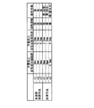
このようにして完成した自動車用ウェザーストリップ10の性能を、従来例の製造方法によって完成した自動車用ウェザーストリップ10の性能と比較すると、図3に示すような表になる。
すなわち、従来例の方法で製造したものによると、サンプル(n1)やサンプル(n2)のように、半製品である押出成形部20と金型を利用して成形した型成形部30との間の隙間が0mmであっても、図5(a)で示したように、押出成形部20と型成形部30との段差Tが2.0mmや1.5mmと大きくなってしまうので、植毛42を指で触った感触が悪いのに加え、大きな段差Tが生じるため外観も悪い。また、サンプル(n3)のように、押出成形部20と型成形部30との間に、図5(b)で示したように、隙間が0.8mmが生じた場合、押出成形部20と型成形部30との段差Tが0.5mmであっても、植毛42の指触感触が悪いのに加え、植毛の欠けによって外観も悪くなってしまう。
これに対して、本発明の第一実施形態の方法で製造したものは、サンプル(n1),サンプル(n2),サンプル(n3)で示すように、押出成形部20と型成形部30との間の隙間が0mmであり、押出成形部20と型成形部30との段差も、0.2mmや0.3mmといった非常に小さい値であるので、植毛42を指で触った感触は良く外観上見栄えも良い。
When the performance of the
That is, according to what was manufactured by the method of the prior art example, like the sample (n1) and the sample (n2), between the
On the other hand, what is manufactured by the method of the first embodiment of the present invention is that the
以上のように構成された本発明の第一実施形態に係る自動車用ウェザーストリップ10によれば、押出成形部20と型成形部30の境界面付近に段差や盛り上がりが生じることがないか、たとえ段差が生じても肉眼では認識できない程度の軽微であるので、植毛42の触感や立毛状態が他と異なることはなく均一である。
According to the
(第二実施形態)
次に、図2を参照にして、本発明の第二実施形態に係る植毛付成形加工品の製造方法について説明する。図2は、本発明の第二実施形態に係る植毛付成形加工品の製造工程を示すもので、図4のA−A線拡大断面図に相当する。本発明の第一実施形態で示したものと同一部分には同一符号を付した。本実施形態では、第一実施形態と同様に、植毛付成形加工品として自動車用のウェザーストリップ(グラスラン)10を例にして説明する。
(Second embodiment)
Next, with reference to FIG. 2, the manufacturing method of the molded processed product with hair transplantation which concerns on 2nd embodiment of this invention is demonstrated. FIG. 2 shows a manufacturing process of the molded product with flocking according to the second embodiment of the present invention, and corresponds to an enlarged sectional view taken along line AA of FIG. The same parts as those shown in the first embodiment of the present invention are denoted by the same reference numerals. In the present embodiment, as in the first embodiment, an automotive weather strip (glass run) 10 will be described as an example of a molded product with flocking.
この第二実施形態に係る製造方法は、第一実施形態に係る製造方法と比較して、含浸工程と、接着剤層形成工程と、型成形部植毛工程と、接着剤層硬化工程が行われる点では共通するが、接着剤層形成工程において、接着剤50を塗布する範囲が異なる。
すなわち、接着剤層形成工程では、図2(b)に示すように、型成形部30の表面に接着剤50を境界面の際から所定距離L分程離して塗布したものである。
Compared with the manufacturing method according to the first embodiment, the manufacturing method according to the second embodiment includes an impregnation step, an adhesive layer forming step, a molded part flocking step, and an adhesive layer curing step. Although common in respect, the range in which the adhesive 50 is applied is different in the adhesive layer forming step.
That is, in the adhesive layer forming step, as shown in FIG. 2B, the adhesive 50 is applied to the surface of the molded
ここに示す所定距離Lとは、含浸工程において、押出成形部20に含浸した水Wが流出して、型成形部30に塗布した接着剤に接触し、接着剤50が水Wに溶解もしくは分散して、押出成形部20と型成形部30との境界面の際まで濡れ広がっていくことができる距離である。
The predetermined distance L shown here means that in the impregnation step, the water W impregnated in the
これによれば、接着剤層形成工程において、押出成形部20と型成形部30との境界面の際まで接着剤50を施さなくても、接着剤50が境界面の際に導かれ、その結果、図2(c),(d)に示すように、パイル42を降りかけると、境界面の際から型成形部30側に均一に植毛42が施されるので、接着剤50を塗布するときに、誤って押出成形部20の植毛41上に塗布したりする危険性を回避することができるとともに、境界面の際まで接着剤50を塗布する必要がないので特に熟練を要せず作業性に優れる。
According to this, in the adhesive layer forming step, even if the adhesive 50 is not applied up to the boundary surface between the extrusion molded
なお、本発明の第一,第二実施形態では、含浸工程の次に接着剤層形成工程を行うようにしたが、含浸させた水と接着剤とが接触し溶解又は分散して押出成形部20と型成形部30の境界面の際において植毛42を見栄えよくできるものであればよいので、含浸工程と接着剤層形成工程を同時に行ってもよく、接着剤層形成工程の次に含浸工程を行うようにしてもよい。
In the first and second embodiments of the present invention, the adhesive layer forming step is performed after the impregnation step, but the impregnated water and the adhesive come into contact with each other to dissolve or disperse, and the extruded portion. As long as the
また、本発明の第一,第二実施形態では、水Wに馴染み易い接着剤として水性接着剤を使用したが、水Wにかえて、押出成形部20側に施された植毛41に、アルコール,メチルエチルケトンなどの水性接着剤と分離しない極性溶剤を含浸させてもよい。あるいは、含浸工程では、押出成形部20側に施された植毛41に、トルエン,キシレンなどの溶剤型接着剤と分離しない非極性溶剤を含浸させ、接着剤層形成工程では、接着剤50を溶剤型接着剤としてもよい。
Moreover, in 1st, 2nd embodiment of this invention, although the water-based adhesive was used as an adhesive which is easy to adapt to water W, it replaces with water W, and the
また、本発明の第一,第二実施形態では、植毛付の成形加工品として自動車用ウェザーストリップ10の製造方法について説明したが、これに限定されるものではなく、植毛が施された押出成形部に接続された型成形部に対して2次加工として植毛を施すようにした植毛付成形加工品の製造方法であれば適用可能である。
In the first and second embodiments of the present invention, the method for manufacturing the
また、本発明の第一,第二実施形態では、一次植毛部位として押出成型品、未植毛部位として押出成型部に接続した型成形部を例にして説明したが、これに限定されるものではなく、例えば、押出成型部に施された植毛が、接着剤塗布不良によって一部欠損している時の手直し加工に応用することが出来る。或いは、植毛を施した押出成型部を一部切り欠き成形し、更にその部位に植毛が必要な場合にも応用することが出来る。 Further, in the first and second embodiments of the present invention, an explanation has been given by taking an example of an extrusion-molded product as a primary flocking site and a molded part connected to an extrusion molding unit as a non-flocked site, but the present invention is not limited thereto. For example, it can be applied to the reworking process when the flocking applied to the extrusion molding part is partially lost due to defective application of the adhesive. Alternatively, the present invention can also be applied to a case where a part of the extrusion-molded part to which flocking has been applied is cut out and then further flocked is required.
10 ウェザーストリップ
20 押出成形部
30 型成形部
41 植毛
42 植毛
50 接着剤
50a 接着剤のはみ出し部
C 見切り線
K 植毛が欠けた部位
L 所定距離
T 段差
DESCRIPTION OF
Claims (7)
前記一次植毛部位と未植毛部位との境界面から一次植毛部位側に施された植毛に水または溶剤を含浸させる含浸工程と、
前記未植毛部位の表面に接着剤を塗布する接着剤層形成工程と、
前記接着剤の上からパイルを静電植毛する二次植毛工程と、
前記パイルが静電植毛された接着剤を熱処理によって硬化させる接着剤層硬化工程を備え、
前記含浸工程で一次植毛部位側に施された植毛に含浸した水または溶剤を流出させ、前記接着剤層形成工程で塗布した接着剤に接触するようにしたことを特徴とする植毛付成形加工品の製造方法。 A method for producing secondary flocking on a non-planted part of a molded product having a primary flocked part and a flocked part having a flocked surface,
An impregnation step of impregnating water or a solvent into the flocking applied to the primary flocking site side from the boundary surface between the primary flocking site and the non-flocked site;
An adhesive layer forming step of applying an adhesive to the surface of the non-planted part;
A secondary flocking step of electrostatic flocking the pile from above the adhesive;
An adhesive layer curing step of curing the adhesive in which the pile is electrostatically implanted by heat treatment;
Molded product with flocking, characterized in that water or solvent impregnated in the flocking applied to the primary flocking site side in the impregnation step is allowed to flow out and contact the adhesive applied in the adhesive layer formation step Manufacturing method.
前記一次植毛部位と未植毛部位との境界面から一次植毛部位側に施された植毛に水または溶剤を含浸させる含浸工程と、
前記未植毛部位の表面に接着剤を前記境界面から離して塗布する接着剤層形成工程と、
前記接着剤の上からパイルを静電植毛する二次植毛工程と、
前記パイルが静電植毛された接着剤を熱処理によって硬化させる接着剤層硬化工程を備え、
前記含浸工程で一次植毛部位側に施された植毛に含浸した水または溶剤を流出させ、前記接着剤層形成工程で塗布した接着剤に接触するようにしたことを特徴とする植毛付成形加工品の製造方法。 A method for producing secondary flocking on a non-planted part of a molded product having a primary flocked part and a flocked part having a flocked surface,
An impregnation step of impregnating water or a solvent into the flocking applied to the primary flocking site side from the boundary surface between the primary flocking site and the non-flocked site;
An adhesive layer forming step of applying an adhesive away from the boundary surface on the surface of the unplanted site;
A secondary flocking step of electrostatic flocking the pile from above the adhesive;
An adhesive layer curing step of curing the adhesive in which the pile is electrostatically implanted by heat treatment;
Molded product with flocking, characterized in that water or solvent impregnated in the flocking applied to the primary flocking site side in the impregnation step is allowed to flow out and contact the adhesive applied in the adhesive layer formation step Manufacturing method.
Priority Applications (1)
| Application Number | Priority Date | Filing Date | Title |
|---|---|---|---|
| JP2008169851A JP5134455B2 (en) | 2008-06-30 | 2008-06-30 | Method for producing molded product with flocking |
Applications Claiming Priority (1)
| Application Number | Priority Date | Filing Date | Title |
|---|---|---|---|
| JP2008169851A JP5134455B2 (en) | 2008-06-30 | 2008-06-30 | Method for producing molded product with flocking |
Publications (2)
| Publication Number | Publication Date |
|---|---|
| JP2010005577A true JP2010005577A (en) | 2010-01-14 |
| JP5134455B2 JP5134455B2 (en) | 2013-01-30 |
Family
ID=41586653
Family Applications (1)
| Application Number | Title | Priority Date | Filing Date |
|---|---|---|---|
| JP2008169851A Expired - Fee Related JP5134455B2 (en) | 2008-06-30 | 2008-06-30 | Method for producing molded product with flocking |
Country Status (1)
| Country | Link |
|---|---|
| JP (1) | JP5134455B2 (en) |
Citations (12)
| Publication number | Priority date | Publication date | Assignee | Title |
|---|---|---|---|---|
| JPS4917828A (en) * | 1972-06-07 | 1974-02-16 | ||
| JPS5493165A (en) * | 1977-12-28 | 1979-07-24 | Toyoda Gosei Kk | Electrostatically flocked article |
| JPS54110660A (en) * | 1978-02-20 | 1979-08-30 | Kenji Nakamura | Preparation of hair planting and grain planting material |
| JPS56108565A (en) * | 1980-01-30 | 1981-08-28 | Nissei:Kk | Electric flocking |
| JPS60214940A (en) * | 1984-04-09 | 1985-10-28 | 虎屋ウ−ル株式会社 | Metal implanted material and manufacture thereof |
| JPS62103135A (en) * | 1985-10-30 | 1987-05-13 | 三英ケミカル株式会社 | Manufacture of thermal inversion type multicolor implanted transfer foundation |
| JPS62277181A (en) * | 1986-05-23 | 1987-12-02 | Toyoda Gosei Co Ltd | Production of molding |
| JPH0292721A (en) * | 1988-09-29 | 1990-04-03 | Kinugawa Rubber Ind Co Ltd | Glass run |
| JPH0312101A (en) * | 1989-06-12 | 1991-01-21 | Mitsuuma:Kk | Manufacture of suede-looking shoes |
| JPH03224660A (en) * | 1990-01-29 | 1991-10-03 | Daikyo Inc | Flocking method of interior parts for automobile |
| JP2002144882A (en) * | 2000-11-07 | 2002-05-22 | Nishikawa Rubber Co Ltd | Sealing structure for door sash corner |
| JP2007131094A (en) * | 2005-11-09 | 2007-05-31 | Toyoda Gosei Co Ltd | Weather strip and its manufacturing method |
-
2008
- 2008-06-30 JP JP2008169851A patent/JP5134455B2/en not_active Expired - Fee Related
Patent Citations (12)
| Publication number | Priority date | Publication date | Assignee | Title |
|---|---|---|---|---|
| JPS4917828A (en) * | 1972-06-07 | 1974-02-16 | ||
| JPS5493165A (en) * | 1977-12-28 | 1979-07-24 | Toyoda Gosei Kk | Electrostatically flocked article |
| JPS54110660A (en) * | 1978-02-20 | 1979-08-30 | Kenji Nakamura | Preparation of hair planting and grain planting material |
| JPS56108565A (en) * | 1980-01-30 | 1981-08-28 | Nissei:Kk | Electric flocking |
| JPS60214940A (en) * | 1984-04-09 | 1985-10-28 | 虎屋ウ−ル株式会社 | Metal implanted material and manufacture thereof |
| JPS62103135A (en) * | 1985-10-30 | 1987-05-13 | 三英ケミカル株式会社 | Manufacture of thermal inversion type multicolor implanted transfer foundation |
| JPS62277181A (en) * | 1986-05-23 | 1987-12-02 | Toyoda Gosei Co Ltd | Production of molding |
| JPH0292721A (en) * | 1988-09-29 | 1990-04-03 | Kinugawa Rubber Ind Co Ltd | Glass run |
| JPH0312101A (en) * | 1989-06-12 | 1991-01-21 | Mitsuuma:Kk | Manufacture of suede-looking shoes |
| JPH03224660A (en) * | 1990-01-29 | 1991-10-03 | Daikyo Inc | Flocking method of interior parts for automobile |
| JP2002144882A (en) * | 2000-11-07 | 2002-05-22 | Nishikawa Rubber Co Ltd | Sealing structure for door sash corner |
| JP2007131094A (en) * | 2005-11-09 | 2007-05-31 | Toyoda Gosei Co Ltd | Weather strip and its manufacturing method |
Also Published As
| Publication number | Publication date |
|---|---|
| JP5134455B2 (en) | 2013-01-30 |
Similar Documents
| Publication | Publication Date | Title |
|---|---|---|
| US20100247859A1 (en) | Method for fabricating injection-molded product | |
| JP2009285893A (en) | Injection molding method and injection molding die | |
| JP2008044573A (en) | Weather strip and manufacturing method thereof | |
| CN101918194B (en) | Extruded strip | |
| CN107848384A (en) | Decorative strip sub-assembly and its manufacture method for vehicle | |
| KR20180061599A (en) | Car interior material manufacturing apparatus | |
| JP5134455B2 (en) | Method for producing molded product with flocking | |
| EP3022036A1 (en) | Method for producing a shaped part, and such a shaped part | |
| CN105563892A (en) | Trim component and method for manufacturing a trim component | |
| CN102161309B (en) | Sealing strip and manufacture method thereof | |
| JP4815622B2 (en) | Method for producing synthetic resin molded article with improved decoration | |
| EP3357758B1 (en) | Vehicle interior component and method for producing same | |
| US20070131012A1 (en) | Hybrid component and associated production method | |
| CN107199963A (en) | Trim components and its assemble method for vehicle | |
| CN1962300A (en) | Weather strip and manufacturing method thereof | |
| JP4802936B2 (en) | Door weather strip manufacturing method | |
| CN101262993A (en) | Method of producing a composite part having a multicoloured surface, and composite part produced in this way | |
| US9137912B1 (en) | Casing of electronic device and method of manufacturing the same | |
| DE102008005778A1 (en) | Method for producing molded part blank for producing covered molded part, particularly for inside paneling of motor vehicles, involves applying interlayer on tool surface of molding tool | |
| JP4745994B2 (en) | Manufacturing method of automobile weather strip or automobile trim | |
| US11485050B2 (en) | Method for producing a trim part for vehicles, using a temporary seal | |
| JP2008049603A (en) | Method for manufacturing molded article | |
| DE102018221678A1 (en) | Decorative molding | |
| DE10322101A1 (en) | Three-layer molded plastic part for automotive interior trim with manufacturing process | |
| US20160250781A1 (en) | Panel assembly and method of forming the same |
Legal Events
| Date | Code | Title | Description |
|---|---|---|---|
| A621 | Written request for application examination |
Free format text: JAPANESE INTERMEDIATE CODE: A621 Effective date: 20110329 |
|
| RD02 | Notification of acceptance of power of attorney |
Free format text: JAPANESE INTERMEDIATE CODE: A7422 Effective date: 20110329 |
|
| A131 | Notification of reasons for refusal |
Free format text: JAPANESE INTERMEDIATE CODE: A131 Effective date: 20120502 |
|
| A977 | Report on retrieval |
Free format text: JAPANESE INTERMEDIATE CODE: A971007 Effective date: 20120502 |
|
| A521 | Request for written amendment filed |
Free format text: JAPANESE INTERMEDIATE CODE: A523 Effective date: 20120625 |
|
| TRDD | Decision of grant or rejection written | ||
| A01 | Written decision to grant a patent or to grant a registration (utility model) |
Free format text: JAPANESE INTERMEDIATE CODE: A01 Effective date: 20121106 |
|
| A01 | Written decision to grant a patent or to grant a registration (utility model) |
Free format text: JAPANESE INTERMEDIATE CODE: A01 |
|
| A61 | First payment of annual fees (during grant procedure) |
Free format text: JAPANESE INTERMEDIATE CODE: A61 Effective date: 20121109 |
|
| FPAY | Renewal fee payment (event date is renewal date of database) |
Free format text: PAYMENT UNTIL: 20151116 Year of fee payment: 3 |
|
| R150 | Certificate of patent or registration of utility model |
Ref document number: 5134455 Country of ref document: JP Free format text: JAPANESE INTERMEDIATE CODE: R150 Free format text: JAPANESE INTERMEDIATE CODE: R150 |
|
| R250 | Receipt of annual fees |
Free format text: JAPANESE INTERMEDIATE CODE: R250 |
|
| R250 | Receipt of annual fees |
Free format text: JAPANESE INTERMEDIATE CODE: R250 |
|
| R250 | Receipt of annual fees |
Free format text: JAPANESE INTERMEDIATE CODE: R250 |
|
| LAPS | Cancellation because of no payment of annual fees |