JP2010005307A - 義足 - Google Patents
義足 Download PDFInfo
- Publication number
- JP2010005307A JP2010005307A JP2008171049A JP2008171049A JP2010005307A JP 2010005307 A JP2010005307 A JP 2010005307A JP 2008171049 A JP2008171049 A JP 2008171049A JP 2008171049 A JP2008171049 A JP 2008171049A JP 2010005307 A JP2010005307 A JP 2010005307A
- Authority
- JP
- Japan
- Prior art keywords
- ring
- ring member
- upper structure
- clamping member
- projecting
- Prior art date
- Legal status (The legal status is an assumption and is not a legal conclusion. Google has not performed a legal analysis and makes no representation as to the accuracy of the status listed.)
- Granted
Links
- 230000002093 peripheral effect Effects 0.000 claims description 13
- 230000008878 coupling Effects 0.000 claims description 3
- 238000010168 coupling process Methods 0.000 claims description 3
- 238000005859 coupling reaction Methods 0.000 claims description 3
- 230000000694 effects Effects 0.000 abstract description 3
- 230000001747 exhibiting effect Effects 0.000 abstract 1
- 230000000717 retained effect Effects 0.000 abstract 1
- 210000002414 leg Anatomy 0.000 description 13
- 239000002184 metal Substances 0.000 description 4
- 238000005452 bending Methods 0.000 description 3
- 210000000629 knee joint Anatomy 0.000 description 2
- 230000033001 locomotion Effects 0.000 description 2
- 210000000689 upper leg Anatomy 0.000 description 2
- 230000037237 body shape Effects 0.000 description 1
- 210000003414 extremity Anatomy 0.000 description 1
- 239000007787 solid Substances 0.000 description 1
Images


Landscapes
- Prostheses (AREA)
Abstract
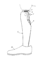
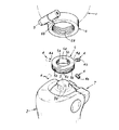
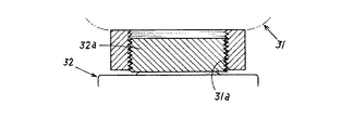
【解決手段】身体に装着される上側構造部1と、この上側構造部1に連結され下端部に接地部2aを有する下側構造部2とからなる義足であって、前記下側構造部2若しくは前記上側構造部1のいずれか一方に突状部3が設けられ、他方に被嵌連結部6が設けられ、この被嵌連結部6にはリング部材5が嵌合されており、前記突状部3は前記リング部材5のリング孔5a内に配されるように構成され、前記リング部材5には前記リング孔5a内に突出する挟持部材4が設けられ、この挟持部材4により前記リング孔5a内の前記突状部3を挟持する構成であり、前記被嵌連結部6により前記挟持部材4の基端部4bを支承して前記挟持部材4を所定位置に保持するものである。
【選択図】図2
Description
2 下側構造部
2a 接地部
3 突状部
4 挟持部材
4b 基端部
5 リング部材
5a リング孔
5b 貫通孔
5c 螺子溝
6 被嵌連結部
Claims (4)
- 身体に装着される上側構造部と、この上側構造部に連結され下端部に接地部を有する下側構造部とからなる義足であって、前記下側構造部若しくは前記上側構造部のいずれか一方に突状部が設けられ、他方に被嵌連結部が設けられ、この被嵌連結部にはリング部材が嵌合されており、前記突状部は前記リング部材のリング孔内に配されるように構成され、前記リング部材には前記リング孔内に突出する挟持部材が設けられ、この挟持部材により前記リング孔内の前記突状部を挟持する構成であり、前記被嵌連結部により前記挟持部材の基端部を支承して前記挟持部材を所定位置に保持するように構成したことを特徴とする義足。
- 請求項1記載の義足において、前記リング部材には複数の貫通孔が設けられ、これらの貫通孔夫々には前記挟持部材が嵌挿されていることを特徴とする義足。
- 請求項1,2いずれか1項に記載の義足において、前記挟持部材の前記リング孔内での突出量は可変可能に構成されていることを特徴とする義足。
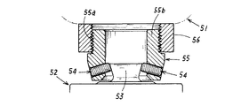
- 請求項1〜3いずれか1項に記載の義足において、前記リング部材の外周面には前記被嵌連結部が螺着する螺子溝が形成されており、この螺子溝が形成される外周面に前記挟持部材を嵌挿する前記貫通孔が開口するように構成されていることを特徴とする義足。
Priority Applications (1)
| Application Number | Priority Date | Filing Date | Title |
|---|---|---|---|
| JP2008171049A JP4741635B2 (ja) | 2008-06-30 | 2008-06-30 | 義足 |
Applications Claiming Priority (1)
| Application Number | Priority Date | Filing Date | Title |
|---|---|---|---|
| JP2008171049A JP4741635B2 (ja) | 2008-06-30 | 2008-06-30 | 義足 |
Publications (2)
| Publication Number | Publication Date |
|---|---|
| JP2010005307A true JP2010005307A (ja) | 2010-01-14 |
| JP4741635B2 JP4741635B2 (ja) | 2011-08-03 |
Family
ID=41586458
Family Applications (1)
| Application Number | Title | Priority Date | Filing Date |
|---|---|---|---|
| JP2008171049A Expired - Fee Related JP4741635B2 (ja) | 2008-06-30 | 2008-06-30 | 義足 |
Country Status (1)
| Country | Link |
|---|---|
| JP (1) | JP4741635B2 (ja) |
Citations (3)
| Publication number | Priority date | Publication date | Assignee | Title |
|---|---|---|---|---|
| JPS51125096A (en) * | 1974-07-26 | 1976-11-01 | Yoshitomi Pharmaceut Ind Ltd | A process for preparing phenoxyancetic acid derivatives. |
| JPH01310660A (ja) * | 1988-03-04 | 1989-12-14 | Chas A Blatchford & Sons Ltd | 義足 |
| JP2001517537A (ja) * | 1997-09-26 | 2001-10-09 | セントリ エイビー | 義肢の固定装置 |
-
2008
- 2008-06-30 JP JP2008171049A patent/JP4741635B2/ja not_active Expired - Fee Related
Patent Citations (3)
| Publication number | Priority date | Publication date | Assignee | Title |
|---|---|---|---|---|
| JPS51125096A (en) * | 1974-07-26 | 1976-11-01 | Yoshitomi Pharmaceut Ind Ltd | A process for preparing phenoxyancetic acid derivatives. |
| JPH01310660A (ja) * | 1988-03-04 | 1989-12-14 | Chas A Blatchford & Sons Ltd | 義足 |
| JP2001517537A (ja) * | 1997-09-26 | 2001-10-09 | セントリ エイビー | 義肢の固定装置 |
Also Published As
| Publication number | Publication date |
|---|---|
| JP4741635B2 (ja) | 2011-08-03 |
Similar Documents
| Publication | Publication Date | Title |
|---|---|---|
| US5507835A (en) | Magnetic prosthetic system | |
| US8470050B2 (en) | Rapid fit modular prosthetic device for accommodating gait alignment and residual limb shape and volume | |
| JP5709111B2 (ja) | 義足における上側義足部と下側義足部との連結構造 | |
| US6398817B1 (en) | Locking device for a prothesis | |
| IL157230A (en) | Fastening device for an orthesis or prosthesis | |
| JPH0951908A (ja) | 下腿用義足 | |
| US5759206A (en) | Apparatus for mounting a prosthesis or the like | |
| JP2005348989A (ja) | 座骨支持式義足 | |
| JP2005193045A (ja) | 無限に位置決め可能なヘッドを有する関節プロテーゼ | |
| US20120259432A1 (en) | Above-the-Knee Modular Prosthesis System | |
| JP2014042813A5 (ja) | ||
| US20050049719A1 (en) | Prosthetic hip joint with side pivot | |
| JP5503274B2 (ja) | 義足用インナーバッグ | |
| EP0531263A1 (fr) | Prothèse pour genou équipée d'une articulation entre les composantes fémorales et tibiales et leurs respectifs pivots endomédullaires | |
| EP1681038A3 (en) | Replicating orthopaedic implant orientation | |
| GB2070439A (en) | Improvements in artificial limbs | |
| JP4741635B2 (ja) | 義足 | |
| JP2011050514A (ja) | 義足組み立て用の測定装置 | |
| US8252066B2 (en) | Pyramid receptacle for coupling a prosthetic limb to a socket | |
| CN218899831U (zh) | 一种足部义肢承筒 | |
| US10792171B2 (en) | Prosthetic adapter module | |
| US20030105531A1 (en) | Multi-axial prosthetic ankle joint | |
| JP2005143618A (ja) | 座骨支持式義足 | |
| US20230000634A1 (en) | Joint prosthesis | |
| KR102838728B1 (ko) | 의지 체결장치 |
Legal Events
| Date | Code | Title | Description |
|---|---|---|---|
| A977 | Report on retrieval |
Free format text: JAPANESE INTERMEDIATE CODE: A971007 Effective date: 20100405 |
|
| A131 | Notification of reasons for refusal |
Free format text: JAPANESE INTERMEDIATE CODE: A131 Effective date: 20100531 |
|
| A521 | Written amendment |
Free format text: JAPANESE INTERMEDIATE CODE: A523 Effective date: 20100730 |
|
| A131 | Notification of reasons for refusal |
Free format text: JAPANESE INTERMEDIATE CODE: A131 Effective date: 20100826 |
|
| A521 | Written amendment |
Free format text: JAPANESE INTERMEDIATE CODE: A523 Effective date: 20101025 |
|
| TRDD | Decision of grant or rejection written | ||
| A01 | Written decision to grant a patent or to grant a registration (utility model) |
Free format text: JAPANESE INTERMEDIATE CODE: A01 Effective date: 20110414 |
|
| A01 | Written decision to grant a patent or to grant a registration (utility model) |
Free format text: JAPANESE INTERMEDIATE CODE: A01 |
|
| A61 | First payment of annual fees (during grant procedure) |
Free format text: JAPANESE INTERMEDIATE CODE: A61 Effective date: 20110506 |
|
| R150 | Certificate of patent or registration of utility model |
Ref document number: 4741635 Country of ref document: JP Free format text: JAPANESE INTERMEDIATE CODE: R150 Free format text: JAPANESE INTERMEDIATE CODE: R150 |
|
| FPAY | Renewal fee payment (event date is renewal date of database) |
Free format text: PAYMENT UNTIL: 20140513 Year of fee payment: 3 |
|
| R250 | Receipt of annual fees |
Free format text: JAPANESE INTERMEDIATE CODE: R250 |
|
| LAPS | Cancellation because of no payment of annual fees |