JP2010004956A - Chair - Google Patents
Chair Download PDFInfo
- Publication number
- JP2010004956A JP2010004956A JP2008165019A JP2008165019A JP2010004956A JP 2010004956 A JP2010004956 A JP 2010004956A JP 2008165019 A JP2008165019 A JP 2008165019A JP 2008165019 A JP2008165019 A JP 2008165019A JP 2010004956 A JP2010004956 A JP 2010004956A
- Authority
- JP
- Japan
- Prior art keywords
- seat
- chair
- edge
- receiving portion
- chair body
- Prior art date
- Legal status (The legal status is an assumption and is not a legal conclusion. Google has not performed a legal analysis and makes no representation as to the accuracy of the status listed.)
- Granted
Links
- 230000036544 posture Effects 0.000 description 45
- 230000000694 effects Effects 0.000 description 6
- 238000009434 installation Methods 0.000 description 2
- 230000003014 reinforcing effect Effects 0.000 description 2
- 238000000638 solvent extraction Methods 0.000 description 2
- 201000010099 disease Diseases 0.000 description 1
- 208000037265 diseases, disorders, signs and symptoms Diseases 0.000 description 1
- 238000000034 method Methods 0.000 description 1
- 238000005192 partition Methods 0.000 description 1
Images


Classifications
-
- A—HUMAN NECESSITIES
- A47—FURNITURE; DOMESTIC ARTICLES OR APPLIANCES; COFFEE MILLS; SPICE MILLS; SUCTION CLEANERS IN GENERAL
- A47C—CHAIRS; SOFAS; BEDS
- A47C11/00—Benches not otherwise provided for
- A47C11/005—Benches not otherwise provided for having multiple separate seats
Abstract
Description
本発明は、複数名を幅方向に並列させて着座させることが可能な椅子に関する。 The present invention relates to a chair capable of seating a plurality of persons in parallel in the width direction.
従来、病院の待合室や、空港のロビー等に主に設置されるものであって、複数名を幅方向に並列させて着座させることが可能な椅子が種々考えられてきている(例えば、特許文献1を参照)。
ところで、例えば、病院の待合室にこのような椅子を設置するにあたって、診療科目や患者の疾患等に応じて適切な座の着座深さ等はそれぞれ異なる。しかし、特許文献1記載のもの等の従来の構成の椅子は、座の着座深さを変更することが不可能なので、病院の待合室にこのような椅子を設置する場合は、それぞれ異なる形状の座を有し座の着座深さがそれぞれ異なる椅子をそれぞれ必要な箇所に設置する必要があった。すなわち、複数種の椅子を予め用意しておき、必要箇所にそれぞれ対応する形状の座を有する椅子を配置する手間を必要としていた。また、病院の待合室に限らず、用途や空間の性質に応じて座の着座深さがそれぞれ異なる椅子を設置する必要がある箇所にこのような椅子を設置する場合においても、また、さらに、1名のみが着座可能な椅子を設置する場合においても、このような手間は同様に必要としていた。
By the way, for example, when such a chair is installed in a waiting room of a hospital, an appropriate seating depth varies depending on a medical subject, a patient's disease, and the like. However, since chairs having a conventional configuration such as that described in
そこで本発明は上記のような課題に着目したものであり、共通の部品構成により複数種の座の着座深さを実現することにより、上述した手間の軽減を図ることを目的としている。 Therefore, the present invention focuses on the above-described problems, and an object thereof is to reduce the labor described above by realizing a seating depth of a plurality of types of seats with a common component configuration.
すなわち、以上のような課題を解決すべく、本発明に係る椅子は、椅子本体と、この椅子本体に一方の縁が前に位置する第1取付姿勢又は他方の縁が前に位置する第2取付姿勢のいずれかを選択して着脱可能に装着される座とを備え、前記椅子本体と前記座との間に、前後方向の相対位置が第1取付姿勢と第2取付姿勢とで異なるように前記座を前記椅子本体に対して位置決めする位置決め機構を設けてなることを特徴とする。 That is, in order to solve the problems as described above, a chair according to the present invention includes a chair body and a first mounting posture in which one edge is located in front of the chair body or a second edge in which the other edge is located in front. A seat that is detachably mounted by selecting one of the mounting postures, and the relative position in the front-rear direction differs between the first mounting posture and the second mounting posture between the chair body and the seat. A positioning mechanism for positioning the seat with respect to the chair body is provided.
このようなものであれば、座を前記第1取付姿勢に装着した状態と第2取付姿勢に装着した状態とでは、座の椅子本体に対する前後方向の相対位置が異なるので、共通の椅子本体及び座を用いつつ、座の取付姿勢を変更することにより着座深さを変更できる。 If it is such, since the relative position in the front-rear direction of the seat with respect to the chair main body is different between the state in which the seat is mounted in the first mounting posture and the state in which the seat is mounted in the second mounting posture, The seating depth can be changed by changing the mounting posture of the seat while using the seat.
前段に述べたような効果を簡単な構成で実現するには、前記椅子本体が、座受部の前側に柱を起立させて設けたものであり、前記位置決め機構が、前記柱と、前記座の一方の縁に形成されその座を前記第1取付姿勢で前記座受部に装着した場合に前記柱に後から嵌る第1凹部と、この第1凹部に対して深さを異ならせて前記座の他方の縁に形成されその座を前記第2取付姿勢で前記座受部に装着した場合に前記柱に後から嵌る第2凹部とを具備してなるものが望ましい。このようなものであれば、前記第1凹部又は第2凹部の深さが異なるので、これら第1凹部又は第2凹部のうちいずれかを柱に嵌めることにより、座の椅子本体に対する相対位置を変更できるからである。 In order to realize the effect described in the previous stage with a simple configuration, the chair body is provided with a column standing on the front side of the seat receiving portion, and the positioning mechanism includes the column, the seat, When the seat is mounted on the seat receiving portion in the first mounting posture, the depth of the first recess is different from that of the first recess. It is desirable to have a second recess that is formed on the other edge of the seat and fits into the column later when the seat is mounted on the seat receiving portion in the second mounting posture. If it is such, since the depth of the said 1st recessed part or the 2nd recessed part differs, the relative position with respect to the chair main body of a seat is set by fitting either of these 1st recessed parts or a 2nd recessed part to a pillar. This is because it can be changed.
さらに、前記座に複数名が並列して着座可能なものであって、各着座者が、柱と柱との間、又は柱と椅子本体の側端縁との間に着座するようにしているものであれば、この柱に1人分の着座スペースを区画する機能をも付与できる。 Further, a plurality of persons can be seated in parallel on the seat, and each seated person sits between the pillars or between the pillars and the side edge of the chair body. If it is a thing, the function which partitions the seating space for one person can also be provided to this pillar.
特に、前記柱が肘当て部材を支持するものであれば、外観を通常の肘掛けを有するロビーチェアと同様にできるので、外観を自然なものに保ちつつ着座深さを変更可能に構成できる。 In particular, if the pillar supports the armrest member, the appearance can be made similar to a lobby chair having a normal armrest, so that the seating depth can be changed while keeping the appearance natural.
そして、前述した課題を簡単な構成により解決するには、前記座が、前記他方の縁から第1の所定距離だけ内方に変位した位置に設けられ座受部の背面に衝き当てることが可能な第1起立壁と、前記一方の縁から前記第1の所定距離と異なる第2の所定距離だけ内方に変位した位置に設けられ前記座受部の背面に衝き当てることが可能な第2起立壁とを有し、前記位置決め機構が、前記座受部と、前記第1起立壁と、前記第2起立壁とを具備してなるものも望ましい。このようなものであれば、前記第1の所定距離と前記第2の所定距離とが異なるので、座の向きを変更し、前記第1起立壁又は第2起立壁のうちいずれかを座受部の背面に衝き当てることにより、座の椅子本体に対する相対位置を変更できるからである。 In order to solve the above-described problem with a simple configuration, the seat can be provided at a position displaced inward by a first predetermined distance from the other edge, and can hit the back surface of the seat receiving portion. A first standing wall, and a second standing wall provided at a position displaced inward from the one edge by a second predetermined distance different from the first predetermined distance and capable of striking against a back surface of the seat receiving portion. It is preferable that the positioning mechanism includes an upright wall, and the positioning mechanism includes the seat receiving portion, the first upright wall, and the second upright wall. In such a case, since the first predetermined distance and the second predetermined distance are different, the orientation of the seat is changed, and either the first standing wall or the second standing wall is received by the seat. This is because the relative position of the seat with respect to the chair body can be changed by striking against the back of the section.
本発明によれば、座の椅子本体への取付姿勢を前記第1取付姿勢又は前記第2取付姿勢のいずれかに選択することにより、座の椅子本体に対する前後方向の相対位置を変更させ、椅子の着座深さを変更することができる。すなわち、同一の形状を有する椅子本体及び座を用意しつつ、座の取付姿勢を変更することのみにより着座深さを変更できる、従って、それぞれ異なる着座深さの座を有する複数種の椅子を用意することなく、共通の椅子本体及び座を使用しつつ各箇所にそれぞれ適切な着座深さの椅子を設置できる。 According to the present invention, the seat relative to the chair main body is changed by selecting either the first mounting posture or the second mounting posture as the mounting posture of the seat on the chair main body, The seating depth can be changed. That is, while preparing a chair body and a seat having the same shape, the seating depth can be changed only by changing the mounting posture of the seat. Accordingly, a plurality of types of chairs having seats with different seating depths are prepared. Without using, a chair with an appropriate seating depth can be installed at each location while using a common chair body and seat.
以下、本発明の実施の一形態を、図面を参照して説明する。 Hereinafter, an embodiment of the present invention will be described with reference to the drawings.
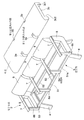
本実施形態に係る椅子1は、主に病院の待合室に設置してなり、図1に全体斜視図、図2に分解斜視図、図3及び図4に要部の側断面図をそれぞれ示すように、椅子本体2と、この椅子本体2に一方の縁が前に位置する第1取付姿勢P又は他方の縁が前に位置する第2取付姿勢Qのいずれかを選択して着脱可能に装着される座3とを具備する。
The
前記椅子本体2は、左右1対に設けた脚体4と、この脚体4に下方から支持させてなる座受部5と、この座受部5の前側に起立させて設けた複数の柱部材6と、この柱部材6に支持させてなる肘当て部材7と、前記座受部5の両側端に設けた側板8と、この側板8に左右両端部を支持させてなる背凭れ9とを具備する。
The
前記座受部5は、前後1対をなして設けた前横架材51及び後横架材52と、これら前横架材51及び後横架材52の左右両端部間及び中間部間をそれぞれ接続する補強材53とを具備し、左右両端部の補強材53を前記脚体4に支持させてなるとともに、前記座3を下方から支持する。
The
前記柱部材6は、前記座受部5の中間部の前面から起立させて設けた中間柱6aと、前記座受部5の両端部の前面から起立させて設けた端部柱6bとからなる。ここで、前記端部柱6bと中間柱6aとの距離、及び中間柱6a間の距離は、いずれもこの椅子本体2の幅寸法の約3分の1となるようにしている。すなわち、前記端部柱6b及び中間柱6aは、1人分の着座空間の両側端に位置する。なお、前記中間柱6aが、請求項中の柱として機能する。また、中間柱6aと端部柱6bとを区別せず総称する際は、柱部材6と称する。
The
前記肘当て部材7は、前端部を前記柱部材6に支持させてなる板状の部材である。そして、この肘当て部材7及び前記柱部材6は、1人分の着座空間の両側端に位置し1人分の着座空間を区画する区画手段として機能する。
The
一方、前記座3は、本実施形態では3人が並列して着座可能である。そして、この座3の長手方向に延伸する両端縁には、前記中間柱6aに後方から嵌めることによりこの座3の前端部の位置決めを行うための第1位置決め凹部3a及び第2位置決め凹部3bを設けている。これら第1位置決め凹部3a及び第2位置決め凹部3bは、それぞれ前記中間柱6aの幅寸法に対応する幅寸法を有する。また、これら第1位置決め凹部3a及び第2位置決め凹部3bは、それぞれ異なる深さを有する。また、前記座3の下面には、前記座受部5を収納可能な取付凹部3cを設けている。この取付凹部3cの第2位置決め凹部3b側の端縁には第1起立壁3c1、第1位置決め凹部3a側の端縁には第2起立壁3c2をそれぞれ形成している。ここで、第2位置決め凹部3b側の端縁から第1起立壁3c1までの距離である第1の所定距離と、第1位置決め凹部3a側の端縁から第2起立壁3c2までの距離である第2の所定距離とは異ならせている。そして、前記第1位置決め凹部3aを前記中間柱6aに後方から嵌めた際には、第1起立壁3c1が前記後横架材52の背面52aに衝き当たるようにしている。その際、第2起立壁3c2と前記前横架材51の前面51aとの間には、わずかな隙間が形成されるようにしている。一方、前記第2位置決め凹部3bを前記中間柱6aに後方から嵌めた際には、第2起立壁3c2が前記後横架材52の背面52aに衝き当たるようにしている。その際、第1起立壁3c1と前記前横架材51の前面51aとの間には、わずかな隙間が形成されるようにしている。なお、前記第1位置決め凹部3a及び第2位置決め凹部3bは、それぞれ請求項中の第1凹部及び第2凹部として機能する。
On the other hand, the
しかして、この椅子1は、椅子本体2と座3との間に、前後方向の相対位置が前記図3の実線に示す第1取付姿勢Pと前記図3の想像線及び図4に示す第2取付姿勢Qとで異なるように前記座3を前記椅子本体2に対して位置決めする位置決め機構Kを有する。
Thus, the
具体的には、前記位置決め機構Kは、前記中間柱6aと、前記第1位置決め凹部3aと、前記第2位置決め凹部3bと、前記後横架材52と、前記第1起立壁3c1と、前記第2起立壁3c2とを具備してなる。さらに詳述すると、この位置決め機構Kは、座3の前記第1位置決め凹部3aを中間柱6aに後から嵌め、第1起立壁3c1を前記後横架材52の背面52aに衝き当てて座3を第1取付姿勢Pで取り付ける際の座3を位置決めする機能、及び座3の前記第2位置決め凹部3bを中間柱6aに後から嵌め、第2起立壁3c2を前記後横架材52の背面52aに衝き当てて座3を第2取付姿勢Qで取り付ける際の座3を位置決めする機能を有する。なお、前記図3及び図4の切断面は、椅子1を前記中間柱6aの側縁と前記第1、第2位置決め凹部3a、3bとの側縁との間である。
Specifically, the positioning mechanism K includes the
すなわち、座3を第1取付姿勢Pで椅子本体2に取り付ける場合は、座3の前記第1位置決め凹部3a側の端縁を前方に配し、座3の後側を持ち上げた姿勢で前記座3の第1位置決め凹部3aを中間柱6aに後から嵌めて座3の前部の位置決めを行い、その後座3を座受部5に載せ置く。その際に、座3の第1起立壁3c1が座受部5の背面すなわち後横架材52の背面52aに衝き当たり、座3の後部が位置決めされる。
That is, when the
一方、座3を第2取付姿勢Qで椅子本体2に取り付ける場合は、座3の前記第2位置決め凹部3b側の端縁を前方に配し、座3の後側を持ち上げた姿勢で前記座3の第2位置決め凹部3bを中間柱6aに後から嵌めて座3の前部の位置決めを行い、その後座3を座受部5に載せ置く。その際に、座3の第2起立壁3c2が座受部5の背面すなわち後横架材52の背面52aに衝き当たり、座3の後部が位置決めされる。
On the other hand, when the
ここで、前記第1取付姿勢Pにおける座3の前端から背凭れ9の前面までの距離d1と、前記第2取付姿勢Qにおける座3の前端から背凭れ9の前面までの距離d2とは異なる。すなわち、前記第1取付姿勢Pにおける着座深さと、前記第2取付姿勢Qにおける着座深さとは異なる。
Here, the distance d1 from the front end of the
そして、座3の取付姿勢の変更は、座3を椅子本体2から取り外し、座3を平面視180度回転させて第1取付凹部3a側の端縁と第2取付凹部3b側の端縁との前後関係を逆転させ、それから座3を上述したような手順で第1取付姿勢P又は第2取付姿勢Qのうち所望の位置に取り付けることにより行うようにしている。
And the change of the attachment attitude | position of the
すなわち、本実施形態の椅子1は以上のように構成しているので、座3を前記第1取付姿勢Pに装着した状態と第2取付姿勢Qに装着した状態とでは、座3の椅子本体2に対する前後方向の相対位置が異なる。従って、共通の椅子本体2及び座3を用いつつ、座3を平面視180度回転させて取付姿勢を変更することにより着座深さを変更できる。すなわち、椅子本体2及び座3の形状を変更することなく、共通の椅子本体2及び座3を用いつつ、座3の取付姿勢の変更のみにより各箇所にそれぞれ適切な着座深さの椅子1を設置できる。
That is, since the
また、前記椅子本体2が、座受部5の前側に柱部材6を起立させて設けたものであり、前記位置決め機構Kが、前記中間柱6aと、前記座3の一方の縁に形成されその座3を前記第1取付姿勢Pで前記座受部5に装着した場合に前記中間柱6aに後から嵌る第1位置決め凹部3aと、この第1位置決め凹部3aに対して深さを異ならせて前記座3の他方の縁に形成されその座3を前記第2取付姿勢Qで前記座受部5に装着した場合に前記中間柱6aに後から嵌る第2位置決め凹部3bとを具備するので、これら第1位置決め凹部3a又は第2位置決め凹部3bのうちいずれかを中間柱6aに嵌めることにより、座3の椅子本体2に対する相対位置を変更できる。従って、前段に述べたような効果を簡単な構成で実現できる。
The
さらに、前記座3に複数名が並列して着座可能なものであって、各着座者が、中間柱6aと中間柱6aとの間、又は中間柱6aと端部柱6bとの間に着座するようにしているので、柱部材6に1人分の着座スペースを区画する機能をも付与できる。
Further, a plurality of persons can be seated in parallel on the
加えて、前記柱部材6が肘当て部材7を支持するので、外観を通常の肘掛けを有するロビーチェアと同様にでき、外観を自然なものに保ちつつ着座深さを変更可能に構成できる。
In addition, since the
そして、前記座3が、前記第2位置決め凹部3b側の端縁から第1の所定距離だけ内方に変位した位置に設けられ後横架材52の背面52aに衝き当てることが可能な第1起立壁3c1と、前記第1位置決め凹部3a側の端縁から前記第1の所定距離と異なる第2の所定距離だけ内方に変位した位置に設けられ前記後横架材52の背面52aに衝き当てることが可能な第2起立壁3c2とを有し、前記位置決め機構Kが、前記座受部5と、前記第1起立壁3c1と、前記第2起立壁3c2とをさらに具備するので、座3の向きを変更し、前記第1起立壁3c1又は第2起立壁3c2のうちいずれかを座受部5の背面に衝き当てることにより、座3の椅子本体2に対する相対位置を変更できる。従って、本実施形態の椅子1の構成による最も重要な効果、すなわち共通の座3を用いつつ、座3の取付姿勢を変更することにより着座深さを変更できる効果を簡単な構成により実現できる。
The
なお、本発明は以上に述べた実施形態に限られない。 The present invention is not limited to the embodiment described above.
例えば、椅子本体の肘当て部材及び柱部材を省略するとともに、座の第1位置決め凹部及び第2位置決め凹部を省略し、以下のような態様を採用してもよい。すなわち、座の一方の端縁から第1の所定距離だけ変位した位置の下面から垂下させて第1垂下壁を設け、また、座の他方の端縁から第1の所定距離と異なる第2の所定距離だけ変位した位置の下面から垂下させて第2垂下壁を設け、これら第1及び第2垂下壁を利用して以下に述べるような位置決め機構を構成してもよい。この位置決め機構は、前記第1及び第2垂下壁をそれぞれ座受部の背面及び座受部の前面に衝き当てることにより座の前後方向の位置決めを行い座を第1取付姿勢に取付可能にしているとともに、前記第1及び第2垂下壁を座受部の前面及び座受部の背面にそれぞれ衝き当てることにより座の前後方向の位置決めを行い座を第2取付姿勢に取付可能にしている。 For example, the elbow rest member and the column member of the chair body may be omitted, and the first positioning recess and the second positioning recess of the seat may be omitted, and the following aspects may be adopted. That is, the first hanging wall is provided by being suspended from the lower surface at a position displaced by a first predetermined distance from one end edge of the seat, and the second second different from the first predetermined distance from the other end edge of the seat. A second hanging wall may be provided by hanging from the lower surface at a position displaced by a predetermined distance, and a positioning mechanism as described below may be configured using these first and second hanging walls. The positioning mechanism positions the seat in the front-rear direction by striking the first and second hanging walls against the back surface of the seat receiving portion and the front surface of the seat receiving portion, respectively, so that the seat can be mounted in the first mounting posture. At the same time, the first and second hanging walls are brought into contact with the front surface of the seat receiving portion and the back surface of the seat receiving portion, thereby positioning the seat in the front-rear direction so that the seat can be mounted in the second mounting posture.
このような構成であっても、座を180度水平回転させることにより、第1取付姿勢で椅子本体に取付可能な状態と、第2取付姿勢で椅子本体に取付可能な姿勢とを切替可能であるので、共通の部品を利用して着座深さが異なる椅子を形成できる。 Even in such a configuration, by horizontally rotating the seat 180 degrees, it is possible to switch between a state that can be attached to the chair body in the first attachment posture and a posture that can be attached to the chair body in the second attachment posture. Therefore, chairs with different seating depths can be formed using common parts.
また、1名のみが着座可能な椅子においても、座の隅部に上述したような実施形態における第1凹部及び第2凹部を設け、これら第1凹部及び第2凹部を脚から上方に延伸させて設けた柱に後から嵌める構成の位置決め機構を設けてもよい。また、座の下面に上述したような実施形態における第1起立壁及び第2起立壁を設け、これら第1起立壁及び第2起立壁を座受の前面及び背面のいずれかに選択的に衝き当てることにより座の前後方向の位置決めを行い、座を第1取付姿勢又は第2取付姿勢に選択的に取付可能にしてもよい。 Further, even in a chair where only one person can sit, the first recess and the second recess in the embodiment as described above are provided at the corner of the seat, and the first recess and the second recess are extended upward from the legs. A positioning mechanism configured to be fitted later on the provided pillar may be provided. In addition, the first standing wall and the second standing wall in the embodiment as described above are provided on the lower surface of the seat, and the first standing wall and the second standing wall are selectively bumped to either the front surface or the rear surface of the seat support. The seat may be positioned in the front-rear direction so that the seat can be selectively attached to the first attachment posture or the second attachment posture.
さらに、柱と柱との間に1名ずつ着座させる態様に限らず、例えば柱と柱との間に2名ずつ着座させる態様を採用してもよい。 Furthermore, it is not limited to a mode in which one person is seated between the columns, and a mode in which two people are seated between the columns may be employed.
加えて、肘当て部材を柱に支持させる代わりに、肘当て部材の後部を背凭れ等に片持ち支持させ、それとは別に天板等のオプション部材を取付可能な柱を座の前方に設け、この柱を利用して座の位置決めを行うようにしてもよい。さらに、座受部の後方に柱を起立させて設け、この柱に座を前方から嵌める構成を採用してもよい。 In addition, instead of supporting the elbow rest member on the pillar, the rear part of the elbow rest member is cantilevered on the backrest, etc., and separately, a pillar on which an optional member such as a top plate can be attached is provided in front of the seat, The seat may be positioned using this pillar. Furthermore, a structure may be employed in which a pillar is provided upright behind the seat receiving portion and the seat is fitted to the pillar from the front.
そして、背凭れを省略した椅子本体を有する椅子であっても、建築壁面に形成した背凭れ部の前方に設置するものであれば、本発明に係るような座及び位置決め機構の構成を採用することにより、本発明の最も主要な効果、すなわち、椅子本体及び座の形状を変更することなく、共通の椅子本体及び座を用いつつ、座の取付姿勢の変更のみにより各箇所にそれぞれ適切な着座深さの椅子を設置できる効果は得られる。 And even if it is a chair which has a chair main part which omitted backrest, if it installs ahead of the backrest part formed in the building wall surface, the composition of a seat and a positioning mechanism concerning the present invention is adopted. Thus, the most important effect of the present invention, that is, without changing the shape of the chair main body and the seat, using the common chair main body and the seat, only by changing the seat mounting posture, respectively, The effect that the chair of the depth can be installed is obtained.
その他、本発明の趣旨を損ねない範囲で種々に変更してよい。 In addition, various changes may be made without departing from the spirit of the present invention.
1…椅子
2…椅子本体
3…座
3a…第1位置決め凹部(第1凹部)
3b…第2位置決め凹部(第2凹部)
5…座受部
6…柱部材
6a…中間柱
K…位置決め機構
P…第1取付姿勢
Q…第2取付姿勢
DESCRIPTION OF
3b ... 2nd positioning recessed part (2nd recessed part)
DESCRIPTION OF
Claims (5)
前記椅子本体と前記座との間に、前後方向の相対位置が第1取付姿勢と第2取付姿勢とで異なるように前記座を前記椅子本体に対して位置決めする位置決め機構を設けてなることを特徴とする椅子。 A chair body, and a seat that is detachably mounted on the chair body by selecting either the first mounting posture in which one edge is positioned forward or the second mounting posture in which the other edge is positioned forward. ,
A positioning mechanism for positioning the seat relative to the chair body is provided between the chair body and the seat so that a relative position in the front-rear direction differs between the first mounting posture and the second mounting posture. Characteristic chair.
Priority Applications (1)
| Application Number | Priority Date | Filing Date | Title |
|---|---|---|---|
| JP2008165019A JP5422824B2 (en) | 2008-06-24 | 2008-06-24 | Chair |
Applications Claiming Priority (1)
| Application Number | Priority Date | Filing Date | Title |
|---|---|---|---|
| JP2008165019A JP5422824B2 (en) | 2008-06-24 | 2008-06-24 | Chair |
Publications (2)
| Publication Number | Publication Date |
|---|---|
| JP2010004956A true JP2010004956A (en) | 2010-01-14 |
| JP5422824B2 JP5422824B2 (en) | 2014-02-19 |
Family
ID=41586133
Family Applications (1)
| Application Number | Title | Priority Date | Filing Date |
|---|---|---|---|
| JP2008165019A Active JP5422824B2 (en) | 2008-06-24 | 2008-06-24 | Chair |
Country Status (1)
| Country | Link |
|---|---|
| JP (1) | JP5422824B2 (en) |
Cited By (1)
| Publication number | Priority date | Publication date | Assignee | Title |
|---|---|---|---|---|
| WO2020059740A1 (en) * | 2018-09-19 | 2020-03-26 | 株式会社ニトリホールディングス | Assemblable sofa |
Citations (4)
| Publication number | Priority date | Publication date | Assignee | Title |
|---|---|---|---|---|
| JPS5990513A (en) * | 1983-10-14 | 1984-05-25 | 鈴木 護 | Height adjustable chair |
| JPS61102145U (en) * | 1984-12-11 | 1986-06-30 | ||
| JP2001008771A (en) * | 1999-06-25 | 2001-01-16 | Kokuyo Co Ltd | Mounting structure of option parts |
| JP2003169726A (en) * | 2001-12-07 | 2003-06-17 | Nissin Mokko Kk | Chair |
-
2008
- 2008-06-24 JP JP2008165019A patent/JP5422824B2/en active Active
Patent Citations (4)
| Publication number | Priority date | Publication date | Assignee | Title |
|---|---|---|---|---|
| JPS5990513A (en) * | 1983-10-14 | 1984-05-25 | 鈴木 護 | Height adjustable chair |
| JPS61102145U (en) * | 1984-12-11 | 1986-06-30 | ||
| JP2001008771A (en) * | 1999-06-25 | 2001-01-16 | Kokuyo Co Ltd | Mounting structure of option parts |
| JP2003169726A (en) * | 2001-12-07 | 2003-06-17 | Nissin Mokko Kk | Chair |
Cited By (1)
| Publication number | Priority date | Publication date | Assignee | Title |
|---|---|---|---|---|
| WO2020059740A1 (en) * | 2018-09-19 | 2020-03-26 | 株式会社ニトリホールディングス | Assemblable sofa |
Also Published As
| Publication number | Publication date |
|---|---|
| JP5422824B2 (en) | 2014-02-19 |
Similar Documents
| Publication | Publication Date | Title |
|---|---|---|
| KR101267804B1 (en) | Tilting seat plate for chair and chair having it | |
| US20080012416A1 (en) | Reversible couch | |
| JP5422824B2 (en) | Chair | |
| JP5383583B2 (en) | Simple toilet | |
| JP5606767B2 (en) | Chair | |
| JP5928009B2 (en) | Chair | |
| JP6723006B2 (en) | Chair | |
| JP6181331B1 (en) | Rollaway bed | |
| JP2008506438A (en) | Chair | |
| JP6494102B2 (en) | Chair | |
| KR101153926B1 (en) | Contracting structure of chest plate for chair | |
| JP5420861B2 (en) | Chair | |
| JP2016067584A (en) | Chair | |
| JP2005131091A (en) | Stand-up assisting chair | |
| USD536201S1 (en) | Seat and back cushion support for a chair | |
| JP2021052818A (en) | Sofa and sofa system | |
| JP3193443U (en) | Portable toilet | |
| JP3100770U (en) | Medical chair armrest flap table | |
| JP4405228B2 (en) | Simple toilet | |
| JP2022105679A (en) | Chair | |
| KR101587896B1 (en) | Single pedestal style audience chair | |
| JP2007020984A (en) | Chair for playing keyboard instrument | |
| JP2021118867A (en) | Backrest for chair | |
| JP3128036U (en) | Tripod chair | |
| KR200412158Y1 (en) | an easy chair |
Legal Events
| Date | Code | Title | Description |
|---|---|---|---|
| A621 | Written request for application examination |
Free format text: JAPANESE INTERMEDIATE CODE: A621 Effective date: 20110520 |
|
| A977 | Report on retrieval |
Free format text: JAPANESE INTERMEDIATE CODE: A971007 Effective date: 20130212 |
|
| A131 | Notification of reasons for refusal |
Free format text: JAPANESE INTERMEDIATE CODE: A131 Effective date: 20130219 |
|
| A521 | Request for written amendment filed |
Free format text: JAPANESE INTERMEDIATE CODE: A523 Effective date: 20130410 |
|
| TRDD | Decision of grant or rejection written | ||
| A01 | Written decision to grant a patent or to grant a registration (utility model) |
Free format text: JAPANESE INTERMEDIATE CODE: A01 Effective date: 20131022 |
|
| A61 | First payment of annual fees (during grant procedure) |
Free format text: JAPANESE INTERMEDIATE CODE: A61 Effective date: 20131104 |
|
| R150 | Certificate of patent or registration of utility model |
Ref document number: 5422824 Country of ref document: JP Free format text: JAPANESE INTERMEDIATE CODE: R150 Free format text: JAPANESE INTERMEDIATE CODE: R150 |
|
| S111 | Request for change of ownership or part of ownership |
Free format text: JAPANESE INTERMEDIATE CODE: R313113 |
|
| SZ03 | Written request for cancellation of trust registration |
Free format text: JAPANESE INTERMEDIATE CODE: R313Z03 |
|
| R350 | Written notification of registration of transfer |
Free format text: JAPANESE INTERMEDIATE CODE: R350 |
|
| R350 | Written notification of registration of transfer |
Free format text: JAPANESE INTERMEDIATE CODE: R350 |
|
| S111 | Request for change of ownership or part of ownership |
Free format text: JAPANESE INTERMEDIATE CODE: R313111 |
|
| R350 | Written notification of registration of transfer |
Free format text: JAPANESE INTERMEDIATE CODE: R350 |
|
| R250 | Receipt of annual fees |
Free format text: JAPANESE INTERMEDIATE CODE: R250 |
|
| R250 | Receipt of annual fees |
Free format text: JAPANESE INTERMEDIATE CODE: R250 |
|
| R250 | Receipt of annual fees |
Free format text: JAPANESE INTERMEDIATE CODE: R250 |