JP2010004487A - Wireless communication system, monitoring apparatus and exchange node - Google Patents
Wireless communication system, monitoring apparatus and exchange node Download PDFInfo
- Publication number
- JP2010004487A JP2010004487A JP2008163695A JP2008163695A JP2010004487A JP 2010004487 A JP2010004487 A JP 2010004487A JP 2008163695 A JP2008163695 A JP 2008163695A JP 2008163695 A JP2008163695 A JP 2008163695A JP 2010004487 A JP2010004487 A JP 2010004487A
- Authority
- JP
- Japan
- Prior art keywords
- monitoring
- failure
- monitored
- group
- information
- Prior art date
- Legal status (The legal status is an assumption and is not a legal conclusion. Google has not performed a legal analysis and makes no representation as to the accuracy of the status listed.)
- Granted
Links
Images


Landscapes
- Data Exchanges In Wide-Area Networks (AREA)
- Mobile Radio Communication Systems (AREA)
- Telephonic Communication Services (AREA)
Abstract
Description
本発明は、無線端末装置が無線で通信を行う無線通信システム、監視装置及び交換ノードの障害監視に関する。 The present invention relates to a wireless communication system in which a wireless terminal device performs wireless communication, a monitoring device, and failure monitoring of an exchange node.
近年、携帯電話やPHSなどの無線通信システムの発達に伴い、広範囲に多数の無線基地局装置やこれらの無線基地局装置をネットワークに接続するための交換ノードが設置されるようになった。この無線通信システムに備えられた無線基地局装置や交換ノードなどのネットワーク機器に障害が発生した場合にそのネットワーク機器を迂回させ、障害が発生したネットワーク機器の迅速な復旧作業に備えて、無線通信システムではネットワーク機器の障害監視を行っている。 In recent years, with the development of wireless communication systems such as mobile phones and PHS, a large number of wireless base station devices and switching nodes for connecting these wireless base station devices to a network have been installed. When a failure occurs in a network device such as a wireless base station device or an exchange node provided in this wireless communication system, the network device is bypassed, and wireless communication is performed in preparation for quick recovery of the failed network device. The system monitors network equipment failures.
従来、無線通信システムでは、この無線通信システムの全てのネットワーク機器の障害監視を一度に行うことは監視装置のCPUへの負荷が大きいためできなく、無線通信システムのネットワークに接続された監視装置が監視対象の全てのネットワーク機器へ障害監視のための障害監視パケットを送信してその障害監視パケットに対する応答を受信するポーリング方式で行っている。そのため、監視対象のネットワーク機器へポーリングを行う周期であるポーリング周期は、監視対象のネットワーク機器の数に比例して長くなる。このポーリング周期が長くなると、ネットワーク機器に障害が発生してからその障害を監視装置が検出するまでの時間が長くなってしまう。特に、近年の無線通信システムでは膨大な数のネットワーク機器が接続されているため、そのポーリング周期はより長くなる。また、監視装置がネットワーク機器へポーリングを行ってそのネットワーク機器に障害が発生していると検出するためには、所定の時間を経過する(タイムアウトする)まで待機しなくてはならず、ポーリング周期の長さは顕著になるという問題がある。 Conventionally, in a wireless communication system, it is not possible to perform failure monitoring of all network devices of this wireless communication system at the same time because the load on the CPU of the monitoring device is large. A polling method is used in which a failure monitoring packet for failure monitoring is transmitted to all the network devices to be monitored and a response to the failure monitoring packet is received. Therefore, the polling cycle, which is a cycle for polling the network device to be monitored, becomes longer in proportion to the number of network devices to be monitored. If this polling cycle becomes long, the time from when a failure occurs in a network device until the monitoring device detects the failure becomes long. In particular, since a huge number of network devices are connected in recent wireless communication systems, the polling cycle becomes longer. In addition, in order for the monitoring device to poll a network device and detect that a failure has occurred in the network device, it must wait until a predetermined time elapses (timeout), and the polling cycle There is a problem that the length of the becomes remarkable.
ここで、このような問題を解決するために、グループ化の繰り返しによりツリー型の階層構造を構築してポーリングを行う技術が知られている(例えば、特許文献1)。
しかしながら、上記の特許文献1に記載の技術では、障害発生を検出するタイムアウト待ちによってポーリング周期が長くなるという問題を解消していない。
However, the technique described in
本発明は、上記問題点を解決するためになされたもので、ネットワーク機器を監視する監視装置に過剰な負荷をかけずにポーリング周期を短くする、無線通信システム、監視装置及び交換ノードを提供することを目的とする。 The present invention has been made to solve the above-described problems, and provides a wireless communication system, a monitoring device, and an exchange node that shorten a polling period without applying an excessive load to a monitoring device that monitors network devices. For the purpose.
上記目的を達成するために、本発明による無線通信システムは、無線端末装置と無線で通信する無線基地局装置と、前記無線基地局装置を制御しIP網に接続される交換ノードと、被監視装置である、前記交換ノードまたは前記無線基地局装置の障害を前記IP網を介して監視する監視装置とを有し、前記監視装置には、前記被監視装置へ障害監視パケットを送信し、前記障害監視パケットに対する応答を受信する一連の処理であるスレッドを第1の上限本数を上限として並列に実行して前記被監視装置の障害を監視する障害監視手段と、前記障害監視パケットに対する応答を所定時間以内に受信したか否かを判断し、前記障害監視パケットに対する応答を所定時間を経過しても受信しない場合に、前記スレッドが次に行う障害の監視を引き継いで処理を行うスレッドを新たに起動して前記第1の上限本数を超えた本数のスレッドを並列に実行するスレッド実行手段とを備えることを特徴とする。 To achieve the above object, a wireless communication system according to the present invention includes a wireless base station device that communicates wirelessly with a wireless terminal device, an exchange node that controls the wireless base station device and is connected to an IP network, and a monitored target A monitoring device that monitors a failure of the switching node or the radio base station device, which is a device, via the IP network, the monitoring device transmits a failure monitoring packet to the monitored device, and A failure monitoring means for monitoring a failure of the monitored device by executing a thread as a series of processes for receiving a response to the failure monitoring packet in parallel up to the first upper limit number, and a response to the failure monitoring packet is predetermined. It is determined whether or not a response to the failure monitoring packet has been received within a predetermined time. Characterized in that it comprises a thread execution means for executing a thread in the number exceeding the newly said first upper limit number to start a thread that performs processing in are in parallel.
また、上記目的を達成するために、本発明による監視装置は、無線端末装置と無線で通信する無線基地局装置と、前記無線基地局装置を制御しIP網に接続される交換ノードと、
被監視装置である前記交換ノードまたは前記無線基地局装置の障害を前記IP網を介して監視する監視装置とを有する無線通信システムの前記監視装置であって、前記被監視装置へ障害監視パケットを送信し、前記障害監視パケットに対する応答を受信する一連の処理であるスレッドを第1の上限本数を上限として並列に実行して前記被監視装置の障害を監視する障害監視手段と、前記障害監視パケットに対する応答を所定時間以内に受信したか否かを判断し、前記障害監視パケットに対する応答を所定時間を経過しても受信しない場合に、前記スレッドが次に行う障害の監視を引き継いで処理を行うスレッドを新たに起動して前記第1の上限本数を超えた本数のスレッドを並列に実行するスレッド実行手段とを備えることを特徴とする。
In order to achieve the above object, a monitoring apparatus according to the present invention includes a radio base station apparatus that communicates with a radio terminal apparatus by radio, an exchange node that controls the radio base station apparatus and is connected to an IP network,
A monitoring device of a wireless communication system having a monitoring device for monitoring a failure of the switching node or the wireless base station device, which is a monitored device, via the IP network, and sending a failure monitoring packet to the monitored device A fault monitoring means for monitoring a fault of the monitored device by executing in parallel a thread that is a series of processes for transmitting and receiving a response to the fault monitoring packet with a first upper limit as an upper limit; and the fault monitoring packet When a response to the failure monitoring packet is not received even after a predetermined time has elapsed, the thread takes over the next failure monitoring and performs processing. Thread execution means for newly starting a thread and executing in parallel the number of threads exceeding the first upper limit number is provided.
また、上記目的を達成するために、本発明による交換ノードは、無線端末装置と無線で通信する無線基地局装置と、前記無線基地局装置を制御しIP網に接続される交換ノードと、被監視装置である前記交換ノードまたは前記無線基地局装置の障害監視を、前記IP網を介して前記被監視装置へ障害監視パケットを送信し前記障害監視パケットに対する応答を受信する一連の処理であるスレッドを第1の上限本数を上限として並列に実行し、前記障害監視パケットに対する応答を所定時間以内に受信したか否かを判断し、前記対する応答を所定時間を経過しても受信しない場合に、前記スレッドが次に行う障害の監視を引き継いで処理を行うスレッドを新たに起動して前記第1の上限本数を超えた第2の上限本数を上限として並列にスレッドを実行して前記交換ノードの障害を監視する監視装置とを有する無線通信システムの交換ノードであって、前記監視装置によって、前記被監視装置を複数のグループにグループ化され、前記グループに属する前記被監視装置の中から代表となる被監視装置と決定されたプライマリ装置は、自らの属するグループの前記被監視装置の障害監視を行い、前記被監視装置のうち少なくとも1つの被監視装置に障害が発生したことを検出すると前記監視装置へ障害が発生したことを通知する第1の障害通知手段を備えることを特徴とする。 In order to achieve the above object, an exchange node according to the present invention includes a radio base station apparatus that communicates with a radio terminal apparatus by radio, an exchange node that controls the radio base station apparatus and is connected to an IP network, Thread that is a series of processes for monitoring a failure of the switching node or the radio base station device that is a monitoring device, transmitting a failure monitoring packet to the monitored device via the IP network, and receiving a response to the failure monitoring packet Are executed in parallel with the first upper limit number being the upper limit, it is determined whether or not a response to the failure monitoring packet has been received within a predetermined time, and the corresponding response is not received even after the predetermined time has elapsed, Threads that perform processing by taking over the next failure monitoring by the thread are newly activated, and threads in parallel up to the second upper limit number exceeding the first upper limit number A switching node of a wireless communication system having a monitoring device that executes and monitors a failure of the switching node, wherein the monitored devices are grouped into a plurality of groups by the monitoring device, and the monitored devices belonging to the group The primary device determined as the representative monitored device from among the monitoring devices performs failure monitoring of the monitored device in the group to which the primary device belongs, and a failure occurs in at least one monitored device of the monitored devices When it is detected that a failure has occurred, the monitoring device is provided with first failure notification means for notifying that a failure has occurred.
本発明によれば、ネットワーク機器を監視する監視装置に過剰な負荷をかけずにポーリング周期を短くすることができる。 According to the present invention, it is possible to shorten the polling cycle without imposing an excessive load on a monitoring device that monitors network devices.
以下、本発明の実施例を、図面を参照して説明する。 Embodiments of the present invention will be described below with reference to the drawings.
図1は、本発明の一実施の形態を示す無線通信システムのブロック図である。
無線通信システムSには、監視装置W、無線基地局装置CS(CS1乃至CSn共通)、交換局100が備えられており、互いにIP網1000を介して接続されている。無線基地局装置CSは、無線端末装置PS1と無線で通信するものである。図1では無線端末装置PS1は1つのみ示したが、多数の無線端末装置PS1が夫々の無線基地局装置CSと無線で通信するようになっている。また、交換局100は、1つのみ示したが、多数の交換局100がIP網1000に接続されているが、ここでは説明の簡略化のため1つのみ示す。この交換局100には、無線基地局装置CSがIP網1000を介して通信するために無線基地局装置CSを制御する少なくとも1つ以上の交換ノードN(N1乃至Nn共通)が設置され、夫々の交換ノードNはIP網1000に接続されている。
FIG. 1 is a block diagram of a wireless communication system showing an embodiment of the present invention.
The wireless communication system S includes a monitoring device W, a wireless base station device CS (common to CS1 to CSn), and a switching center 100, which are connected to each other via an
また、監視装置Wは、この無線通信システムSを構成する無線基地局装置CSや交換ノードNなどのネットワーク機器(被監視装置)に障害が生じていないかを監視するものである。監視装置Wが行う監視は、ポーリング方式であるものとする。ポーリング方式とは、ネットワークに接続された機器の情報を収集する目的で、通常は周期的に要求メッセージを送信する処理(障害監視手段)のことである。このポーリング方式を用いた障害監視は、監視装置Wからネットワーク機器へ障害監視パケットを送信し、ネットワーク機器がこの障害監視パケットに応答すると、監視装置Wはネットワーク機器が正常に動作していることを検出することができる。また、ネットワーク機器が一定時間以内にこの障害監視パケットに応答しないと、監視装置Wはネットワーク機器に障害が生じていることを検出することができる。 The monitoring device W monitors whether a failure has occurred in network devices (monitored devices) such as the radio base station device CS and the exchange node N that constitute the radio communication system S. The monitoring performed by the monitoring device W is assumed to be a polling method. The polling method is a process (fault monitoring means) that normally transmits a request message periodically for the purpose of collecting information on devices connected to the network. Fault monitoring using this polling method transmits a fault monitoring packet from the monitoring device W to the network device, and when the network device responds to the fault monitoring packet, the monitoring device W confirms that the network device is operating normally. Can be detected. If the network device does not respond to the failure monitoring packet within a certain time, the monitoring device W can detect that a failure has occurred in the network device.
図2は、無線通信システムに備えられた無線基地局装置CS(CS1乃至CSn共通)の構成を示したブロック図である。
無線基地局装置CSには、無線インターフェース部11、IPインターフェース部12、主演算部13、および記憶部14が備えられており、無線インターフェース部11、IPインターフェース部12、および記憶部14は、主演算部13に接続されている。無線インターフェース部11は、無線端末装置PS1と無線で通信するものであり、IPインターフェース部12は、無線インターフェース部11で無線端末装置PS1から受信したデータをIP網1000へ送信したり、無線インターフェース部11で無線端末装置PS2へ送信するデータをIP網1000から受信したりするものである。記憶部14は、無線インターフェース部11またはIPインターフェース部12で通信するデータや無線端末装置PS1へ着呼をかけるために設定されたページングエリアの情報などを記憶するものである。主演算部13は、IP網1000から受信した無線端末装置PS1への着呼をかけるか否かを記憶部14を参照して判断し、着呼をかけると判断すると、無線インターフェース部11から無線端末装置PS1へ着呼をかけるなど、無線基地局装置CSの全体を制御するものである。
FIG. 2 is a block diagram illustrating a configuration of a radio base station apparatus CS (common to CS1 to CSn) provided in the radio communication system.
The radio base station apparatus CS includes a
図3は、無線通信システムSに備えられた交換ノードN(N1乃至Nn共通)の構成を示したブロック図である。
交換ノードNには、IPインターフェース部21、保守インターフェース部22、主演算部23、および記憶部24が備えられており、IPインターフェース部21、保守インターフェース部22、および記憶部24は、主演算部23に接続されている。IPインターフェース部21は、IP網1000を介して無線基地局装置CSや他の交換ノードNと通信を行うものであり、保守インターフェース部22は、IP網1000を介して、監視装置Wと通信を行うものである。記憶部14は、IPインターフェース部21または保守インターフェース部22で通信するデータ、無線端末装置PS1へ着呼をかけるために設定されたページングエリアの情報、および自らの交換ノードNのIDやネットワークアドレスなどの交換ノードNの情報を記憶するものである。この交換ノードNのIDには、この交換ノードNが設置されている都道府県の情報や交換局の情報などが含まれている。また、主演算部23は、IP網1000から受信した無線端末装置PS1への着呼を無線基地局装置CSへ送信するために記憶部24に記憶されているページングエリアの情報を参照したり、監視装置Wから送られてくる障害監視パケットに応答したりするなど、交換ノードNの全体を制御するものである。
FIG. 3 is a block diagram showing a configuration of an exchange node N (common to N1 to Nn) provided in the radio communication system S.
The exchange node N includes an
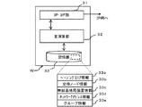
図4は、無線通信システムSに備えられた監視装置Wの構成を示したブロック図である。
監視装置Wには、IPインターフェース部31、主演算部32、記憶部33が備えられており、IPインターフェース部31および記憶部33は、主演算部32に接続されている。IPインターフェース部31は、IP網1000を介して、無線通信システムSに備えられている無線基地局装置CSや交換ノードNなどのネットワーク機器の障害監視を行う障害監視パケットを送信し、それらのネットワーク機器から障害監視パケットに対する応答を受信するものである。記憶部33には、IPインターフェース部31で受信した自らの監視装置Wが監視するネットワーク機器の障害監視情報を主演算部32によって記憶される。その他には、無線端末装置PS1へ着呼をかけるために設定されたページングエリアの情報(ページングエリア情報記憶手段)33a、交換ノードNが設置されている都道府県の情報や交換局の情報を含む交換ノードIDなどの交換ノード情報(交換局情報記憶手段、都道府県情報記憶手段)33b、無線基地局装置CSがどの交換ノードNに制御されているかを示す無線基地局装置情報33c、無線通信システムで使用されているネットワークアドレスの情報(ネットワークアドレス記憶手段)33d、および後述する監視装置Wが行う被監視装置のグループ化についてのグループ情報(グループ情報記憶手段)33eを記憶したりするものである。このグループ情報33eには、監視装置Wがグループ化したグループにどの被監視装置が属し、そのグループの代表となる装置(後に詳述するプライマリ装置)がどの被監視装置であるかの情報が含まれる。監視装置Wが被監視装置をグループ化すると、その情報はグループ情報33eが記憶される記憶部33へ記憶するようになっている。
FIG. 4 is a block diagram illustrating a configuration of the monitoring device W provided in the wireless communication system S.
The monitoring device W includes an
次に、図5乃至図7を参照して監視装置Wがネットワーク機器の障害監視を行う処理について示す。 Next, a process in which the monitoring apparatus W performs the failure monitoring of the network device will be described with reference to FIGS.
図5は、監視装置Wが障害監視を行う監視対象のネットワーク機器(被監視装置)を示した図である。
監視装置Wは、無線通信システムが有する全てのネットワーク機器への障害監視を行うと、全てのネットワーク機器へ障害監視を行うポーリング周期が非常に長くなるため、本実施例ではネットワーク機器を複数のグループにグループ化し、そのグループを代表してグループ内のネットワーク機器を監視するプライマリ装置を決定し(グループ化手段)、夫々のグループのプライマリ装置を監視装置Wが直接監視するようにしている(プライマリ装置監視手段)。このように、監視装置Wが直接監視するネットワーク機器を減らすことで、監視装置Wへの負荷を軽減することができるためポーリング周期を短くすることが可能である。さらに、監視装置Wが直接監視するネットワーク機器を減らすことで、監視装置Wから送信される障害監視パケットによるネットワーク負荷も軽減することができる。
FIG. 5 is a diagram illustrating a monitoring target network device (monitored device) on which the monitoring device W performs failure monitoring.
When the monitoring apparatus W performs failure monitoring on all network devices included in the wireless communication system, the polling cycle for performing failure monitoring on all network devices becomes very long. The primary device that monitors the network devices in the group is determined on behalf of the group (grouping means), and the monitoring device W directly monitors the primary device of each group (primary device). Monitoring means). In this way, by reducing the number of network devices that are directly monitored by the monitoring device W, the load on the monitoring device W can be reduced, so that the polling cycle can be shortened. Furthermore, by reducing the number of network devices that the monitoring device W directly monitors, the network load due to the failure monitoring packet transmitted from the monitoring device W can be reduced.
また、監視装置Wに監視されるプライマリ装置は、グループ内の他のネットワーク機器を監視するようになっている。このプライマリ装置が行う障害監視の方法については、実施例2で詳述する。 Further, the primary device monitored by the monitoring device W monitors other network devices in the group. The failure monitoring method performed by the primary device will be described in detail in the second embodiment.
ここで、監視装置Wが行うネットワーク機器のグループ化について説明する。グループ化の方法としては多数あるが、本実施例では4つの方法について述べる。
(グループ化基準1)
まず1つ目の方法は、ネットワーク機器に設定されているネットワークアドレスを基にグループ化を行うものである。
監視装置Wの記憶部33dには、無線通信システムで使用されているネットワークアドレスの情報が記憶されている。監視装置Wは、このネットワークアドレスの情報を参照して、同一のネットワークアドレスを割当てられているネットワーク機器を1つのグループとする。ネットワークアドレスは、無線通信システムを複数のネットワークに分割し、そのネットワークを示すアドレスである。そのため、同一のネットワークアドレスを割当てられているネットワーク機器は、物理的にも互いに近距離であることが多い。
Here, grouping of network devices performed by the monitoring apparatus W will be described. Although there are many grouping methods, four methods will be described in this embodiment.
(Grouping standard 1)
The first method is to perform grouping based on the network address set in the network device.
The
このように、同一のネットワークアドレスを割当てられているネットワーク機器を1つのグループとすることで、位置ごとにグループ化され、監視装置Wから送信される障害監視パケットによるネットワーク負荷を分散させることができる。また、同一グループ内でもプライマリ装置が障害監視を行うが、プライマリ装置がグループ内のネットワーク機器を監視するための障害監視パケットを物理的に近距離にのみ送信するため、ネットワーク負荷を軽減することができる。 In this way, network devices to which the same network address is assigned are grouped into one group, so that the network load due to the failure monitoring packet that is grouped by location and transmitted from the monitoring device W can be distributed. . In addition, although the primary device performs failure monitoring within the same group, the primary device transmits a failure monitoring packet for monitoring network devices in the group only physically at a short distance, thus reducing the network load. it can.
(グループ化基準2)
2つ目の方法は、ネットワーク機器が設置されている都道府県を基にグループ化を行うものである。
監視装置Wの記憶部33bには交換ノード情報が記憶され、監視装置Wの記憶部33cには無線基地局情報が記憶されている。交換ノード情報は、例えば交換ノードIDが記憶され、その交換ノードIDには、都道府県の情報が含まれるため、この交換ノードIDを参照することで、交換ノードNが設置されている都道府県がわかる。また、無線基地局情報は、どの交換ノードNに制御されているかの情報を含むため、無線基地局装置CSと交換ノードNの接続の様子がわかる。監視装置Wは、交換ノード情報と無線基地局情報を参照することで、ネットワーク機器を都道府県毎にグループ化することができる。
(Grouping standard 2)
The second method is to perform grouping based on the prefecture where the network device is installed.
Exchange node information is stored in the
このように、ネットワーク機器を都道府県毎にグループ化することで、ネットワークアドレスを基にグループ化を行う場合と同様の効果を期待できる。 In this way, by grouping network devices into prefectures, the same effect as when grouping based on network addresses can be expected.
(グループ化基準3)
3つ目の方法は、ネットワーク機器が設置されているページングエリアの情報を基にグループ化を行うものである。
監視装置Wの記憶部33aには無線通信システムSのページングエリアの情報が記憶されている。ページングエリアの情報は、複数の無線基地局装置CSや1つまたは複数の交換ノード毎に無線端末装置PS1への着呼をかける範囲を示した情報である。監視装置Wがこのページングエリアの情報を参照することで、ネットワーク機器をページングエリア毎にグループ化することができる。
(Grouping standard 3)
The third method is to perform grouping based on the information of the paging area where the network device is installed.
Information of the paging area of the wireless communication system S is stored in the
このように、ネットワーク機器をページングエリア毎にグループ化することで、ネットワークアドレス毎や都道府県毎にグループ化を行う場合と同様の効果を期待できる。また、ページングエリアの情報を基にしたグループ化は、交換ノードIDに都道府県の情報を含むような無線通信システムでなくてもグループ化することができる。 In this way, by grouping network devices for each paging area, the same effect as when grouping for each network address or each prefecture can be expected. Further, the grouping based on the information of the paging area can be grouped even if the wireless communication system does not include the information of the prefecture in the exchange node ID.
(グループ化基準4)
4つ目の方法は、交換ノードNが格納されている交換局100の情報を基にグループ化を行うものである。
監視装置Wの記憶部33bには、交換ノード情報が記憶されている。交換ノード情報は、例えば交換ノードIDが記憶され、その交換ノードIDには、その交換ノードNが格納される交換局100の情報が含まれる。そのため、この交換ノードIDからどの交換ノードNが交換局100に格納されているかがわかり、同一の交換局100に格納される交換ノードNおよびその交換ノードNが制御する無線基地局装置CSを1つのグループとすることができる。
(Grouping standard 4)
The fourth method is to perform grouping based on information of the switching center 100 in which the switching node N is stored.
The
このように、ネットワーク機器を交換局100毎にグループ化することにより、グループ内の交換ノードNは同一の交換局100内に格納されているため、プライマリ装置が行うグループ内の障害監視の距離が近くなり、ネットワーク負荷をさらに低減することができる。 In this way, by grouping network devices for each switching office 100, the switching nodes N in the group are stored in the same switching center 100, so that the distance of fault monitoring in the group performed by the primary device is reduced. Network load can be further reduced.
ここまで4つのグループ化基準について記載したが、これらのグループ化方法を複数または全てを組み合わせることでより効果的な障害監視を行うことができる。例えば、夫々のグループ化基準によってグループ化される1グループの大きさは、都道府県毎のグループが一番大きく、次いで交換局毎、ページングエリア毎となる。また、ネットワークアドレス毎にグループ化されたグループは、無線通信ネットワークの規模に依存した大きさになる。このようなグループの大きさを利用して、グループを階層化したりすることもできる。グループを階層化することで、ポーリング周期の更なる短縮が可能である。 Although four grouping criteria have been described so far, more effective fault monitoring can be performed by combining a plurality or all of these grouping methods. For example, the size of one group grouped according to each grouping standard is the largest for each prefecture, followed by each switching center and each paging area. The group grouped for each network address has a size depending on the scale of the wireless communication network. The group can be hierarchized using such a group size. By hierarchizing groups, the polling cycle can be further shortened.
図6は、監視装置Wの処理方法を示した模式図である。
監視装置Wは、監視対象のネットワーク機器へ障害監視パケットを送信してその応答を受信するという処理を繰り返し行う。この一連の処理をスレッドという。監視装置Wは、このスレッドを処理可能な本数を上限として並列に実行し、複数のスレッドを並列処理するようになっている。本実施例では、監視装置Wが処理可能なスレッドの第1の上限本数nが8本の場合を示す。また、図7の説明の際に詳述する「待機時間の有効活用」のために設けられた、この上限本数nを超えた本数のスレッドを起動して実行する際の第2の上限本数mを16本とした場合を示す。スレッド番号は、第2の上限本数mである16まで用意され、起動スレッド番号には、起動したスレッド番号、または次の処理を行うスレッド番号が記入されるようになっている。通常はスレッド番号8までスレッドが起動される。次の処理を行うスレッド番号とは、図7の説明で詳述するが、監視対象からの応答がなく障害が発生していると検出するまでの待機時間に新たに起動するスレッドの番号のことである。
FIG. 6 is a schematic diagram illustrating a processing method of the monitoring device W.
The monitoring device W repeatedly performs a process of transmitting a failure monitoring packet to the network device to be monitored and receiving a response thereto. This series of processing is called a thread. The monitoring device W executes the threads in parallel up to the maximum number that can be processed, and processes a plurality of threads in parallel. In the present embodiment, a case where the first upper limit number n of threads that can be processed by the monitoring apparatus W is eight is shown. In addition, the second upper limit number m when starting and executing threads exceeding the upper limit number n provided for “effective use of standby time” described in detail in the description of FIG. 7. The case where 16 is set is shown. The thread number is prepared up to 16 which is the second upper limit number m, and the activated thread number or the thread number for performing the next processing is entered in the activated thread number. Normally, threads are activated up to
図6(a)は、監視対象のネットワーク機器が全て正常に動作している場合に、監視装置Wが処理可能な8本のスレッドを実行している場合のスレッドを示している。図6(b)は、既に8本のスレッドが実行中に、スレッド番号3のスレッドが待機状態となり、新たにスレッド9を起動した場合を示している。図6(c)は、スレッドが待機状態になり新たにスレッドを起動する処理を繰り返し、第2の上限本数mである16本までスレッドが起動させている状態を示している。
FIG. 6A shows threads when eight threads that can be processed by the monitoring apparatus W are executed when all the network devices to be monitored are operating normally. FIG. 6B shows a case where the thread with the
このように、第1の上限本数nを超えてスレッドを起動することで効率的にポーリングを行ってポーリング周期を短縮することができる。また、第1の上限本数nよりも多い第2の上限本数mを設けることで、監視装置Wへ過剰な負荷がかかることを防ぐことができる。 As described above, the polling cycle can be shortened by efficiently polling by starting the threads exceeding the first upper limit number n. In addition, by providing the second upper limit number m, which is larger than the first upper limit number n, it is possible to prevent an excessive load from being applied to the monitoring device W.
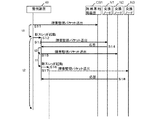
図7は、監視装置Wが行うネットワーク機器の障害監視を行う処理を示した無線通信システム全体のシーケンス図である。
ここでは、監視装置Wが、無線基地局装置CS1と交換ノードN1、N2、N3の障害監視を行う場合に、スレッドの待機状態を利用して第1の上限本数を超えた本数のスレッドを起動する処理(スレッド実行手段)を示す。
FIG. 7 is a sequence diagram of the entire wireless communication system showing processing for monitoring a failure of the network device performed by the monitoring apparatus W.
Here, when the monitoring device W performs failure monitoring of the radio base station device CS1 and the exchange nodes N1, N2, and N3, the number of threads exceeding the first upper limit number is activated using the thread standby state. Processing (thread execution means) to be performed is shown.
まず、監視装置Wは、無線基地局装置CS1へ障害監視パケットを送信する(S11)。無線基地局装置CS1およびネットワークが正常であれば、この障害監視パケットに対する無線基地局装置CS1からの応答は、監視装置Wが障害監視パケットを送信してからt1秒未満の間に受信し、1つのスレッドで障害監視パケットの送信、および応答を繰り返す。このスレッドを複数起動し、監視装置Wが処理可能な第1の上限本数であるn本まで同時に並列処理を行う。 First, the monitoring device W transmits a failure monitoring packet to the radio base station device CS1 (S11). If the radio base station apparatus CS1 and the network are normal, the response from the radio base station apparatus CS1 to this fault monitoring packet is received within t1 seconds after the monitoring apparatus W transmits the fault monitoring packet. Repeat sending and monitoring of fault monitoring packets in one thread. A plurality of these threads are activated, and parallel processing is simultaneously performed up to the first upper limit number n that can be processed by the monitoring device W.
この例では、無線基地局装置CS1からt1秒未満の間に応答を受信していない。この場合は、無線基地局装置CS1は障害が発生して応答不能か、応答が遅延しているかのどちらかの状態である。この応答を受信するまで、またはこの応答の受信待ちタイムアウトまで(t2秒)の待機時間は、スレッドは待機状態なのでそのスレッドの分の負荷はかからない。そこで、監視装置Wが障害監視パケットを送信してからt1秒未満の間に応答を受信しない場合は、タイムアウトとなるt2秒の経過を待たずに、監視装置Wは障害監視パケットを送信してからt1秒後に新たにスレッドを起動し(S12)、この待機時間を有効利用する。このスレッドは、無線基地局装置CS1の次の監視対象である交換ノードN1へ障害監視を行うものである。新たにスレッドが起動されると、監視装置Wは、障害監視パケットを交換ノードN1へ送信する(S13)。この障害監視パケットを受信した交換ノードN1から、監視装置Wは応答を受信する(S14)。 In this example, no response is received from the radio base station apparatus CS1 for less than t1 seconds. In this case, the radio base station apparatus CS1 is in a state where either a failure occurs and the response is impossible or the response is delayed. The waiting time until the response is received or until the response reception waiting time-out (t2 seconds) is not loaded because the thread is in a waiting state. Therefore, if the monitoring device W does not receive a response in less than t1 seconds after transmitting the failure monitoring packet, the monitoring device W transmits the failure monitoring packet without waiting for elapse of t2 seconds that time out. After t1 seconds from the start, a new thread is activated (S12), and this standby time is effectively used. This thread is for monitoring a failure to the switching node N1 that is the next monitoring target of the radio base station apparatus CS1. When the thread is newly activated, the monitoring device W transmits a failure monitoring packet to the exchange node N1 (S13). The monitoring device W receives a response from the exchange node N1 that has received the failure monitoring packet (S14).
監視装置Wが応答を受信すると、応答を受信してからt0秒後に次の障害監視パケットを次の監視対象である交換ノードN2へ送信する(S15)。交換ノードN2からの応答が障害監視パケットを送信してからt1秒未満の間に受信しなかったので、監視装置Wは、さらに新たにスレッドを起動する(S16)。このスレッドは、次の監視対象である交換ノードN3へ障害監視パケットを送信する(S17)。その後、処理S12で起動したスレッドがタイムアウトするt2秒を経過する前に、交換ノードN2から応答を受信する(S18)。タイムアウトするt2秒を経過する前に応答があったので、監視装置Wは交換ノードN2を正常と判断して交換ノードN2へ障害監視パケットを送信したスレッドを終了する。一方、処理S16で起動したスレッドは交換ノードN3からの応答を受信後、次の監視対象であるネットワーク機器へ障害監視パケットを送信し、同様の処理を繰り返す。 When the monitoring device W receives the response, the next failure monitoring packet is transmitted to the switching node N2 that is the next monitoring target t0 seconds after the response is received (S15). Since the response from the exchange node N2 has not been received within t1 seconds after transmitting the failure monitoring packet, the monitoring device W further activates a thread (S16). This thread transmits a failure monitoring packet to the next switching node N3 to be monitored (S17). Thereafter, a response is received from the exchange node N2 before the time t2 seconds when the thread activated in the process S12 times out (S18). Since there is a response before elapse of t2 seconds that time out, the monitoring apparatus W determines that the switching node N2 is normal and terminates the thread that has transmitted the failure monitoring packet to the switching node N2. On the other hand, after receiving the response from the exchange node N3, the thread activated in process S16 transmits a failure monitoring packet to the next network device to be monitored, and repeats the same process.
このように、監視装置Wが障害監視を行う処理であるスレッドを、監視装置Wが同時に並列処理可能な第1の上限本数nまで実行中に、そのうちのスレッドが待機状態となったとき、その待機状態を利用するために新たにスレッドを起動することで、監視装置に過剰な負荷をかけずにポーリング周期を短くすることができる。 In this way, when the monitoring device W is executing a thread for performing failure monitoring up to the first upper limit number n that the monitoring device W can simultaneously process, when those threads are in a standby state, By starting a new thread to use the standby state, the polling cycle can be shortened without applying an excessive load to the monitoring device.
また、障害監視パケットを送信してから応答があるまでの時間は、通常ある平均値の付近に分布するが、オペレータによる被監視装置の操作やネットワークの遅延により大きくばらつきが発生することがある。この特性を利用して、そのばらつきを障害として誤検出することを防止するために、障害を検出するための障害監視パケットに対する応答の受信待ちタイムアウトまで(t2秒)の待機時間を短くすることなく、障害検出のための応答待機時間とは別に、所定時間(t1秒)を平均値の分布を越えた時間とすることにより、応答待機中のCPUなどのリソースを利用して第1の上限本数(n本)を超えた本数のスレッド起動を可能とする。 In addition, the time from when a failure monitoring packet is transmitted to when there is a response is normally distributed in the vicinity of a certain average value, but may vary greatly depending on the operation of the monitored device by the operator and the delay of the network. By utilizing this characteristic, in order to prevent the variation from being erroneously detected as a failure, the waiting time until the reception wait time-out of the response to the failure monitoring packet for detecting the failure (t2 seconds) is not shortened. In addition to the response waiting time for failure detection, the first upper limit number is obtained by using a resource such as a CPU waiting for a response by setting a predetermined time (t1 second) as a time exceeding the distribution of the average value. The number of threads exceeding (n) can be activated.
実施例1では、監視装置Wが無線通信システムSに備えられている交換ノードNや無線基地局装置CSなどのネットワーク機器を監視する処理について説明した。実施例2では、実施例1でグループ化したグループ内のネットワーク機器の障害監視(第1の障害通知手段)について説明する。 In the first embodiment, the process in which the monitoring apparatus W monitors network devices such as the exchange node N and the radio base station apparatus CS provided in the radio communication system S has been described. In the second embodiment, failure monitoring (first failure notification means) of network devices in the group grouped in the first embodiment will be described.
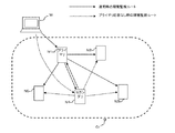
図8は、監視装置Wが実施例1に記載の何れかのグループ化基準によりグループ化したグループの障害監視とそのグループ内の障害監視を行う場合の模式図である。無線通信システムSの構成および交換ノードNの構成は、実施例1と同じであるため同一符号を付して説明を省略する。
図8中に示す実線矢印は、プライマリ装置に障害が発生していない場合の障害監視ルートである。監視装置Wは、交換ノードN1〜N5で構成されるグループGrのプライマリ装置の障害監視を行っている。プライマリ装置は、交換ノードN1である場合を示した。このプライマリ装置は、グループGrの交換ノードN2〜N5の障害監視を行う。プライマリ装置がグループGrで障害が発生している交換ノードNを検出した場合には、障害が発生している交換ノードNの情報を監視装置Wへ通知するようになっている。
FIG. 8 is a schematic diagram when the monitoring apparatus W performs failure monitoring of a group grouped according to any of the grouping criteria described in the first embodiment and failure monitoring within the group. Since the configuration of the wireless communication system S and the configuration of the exchange node N are the same as those in the first embodiment, the same reference numerals are given and description thereof is omitted.
The solid arrow shown in FIG. 8 is a failure monitoring route when no failure has occurred in the primary device. The monitoring device W performs failure monitoring of the primary device of the group Gr composed of the exchange nodes N1 to N5. The case where the primary device is the exchange node N1 is shown. This primary device performs failure monitoring of the exchange nodes N2 to N5 of the group Gr. When the primary device detects an exchange node N in which a failure has occurred in the group Gr, information on the exchange node N in which the failure has occurred is notified to the monitoring device W.
また、監視装置Wがプライマリ装置を決定する際に、このグループGrの障害監視を行うプライマリ装置に障害が発生した場合にプライマリ装置に代わってグループGrの障害監視を行うセカンダリ装置を監視装置Wが決定しておく。このセカンダリ装置は、自らの交換ノードN4が障害監視を開始するためにプライマリ装置に障害が発生したことを検出する必要がある。そのために、プライマリ装置が障害監視している間にセカンダリ装置はプライマリ装置の障害監視を行うようになっている(第2の障害通知手段)。 In addition, when the monitoring device W determines the primary device, if the failure occurs in the primary device that performs the failure monitoring of the group Gr, the monitoring device W selects the secondary device that performs the failure monitoring of the group Gr instead of the primary device. Make a decision. This secondary device needs to detect that a failure has occurred in the primary device in order for its own exchange node N4 to start monitoring the failure. For this purpose, the secondary device monitors the failure of the primary device while the primary device is monitoring the failure (second failure notification means).
図8中に示す破線矢印は、プライマリ装置に障害が発生した場合の障害監視ルートである。
監視装置Wは、プライマリ装置からの応答がないのでセカンダリ装置の障害監視を行うように切替え、セカンダリ装置はN1〜N3、N5の障害監視を行う。
A broken-line arrow shown in FIG. 8 is a failure monitoring route when a failure occurs in the primary device.
Since there is no response from the primary device, the monitoring device W is switched to monitor the failure of the secondary device, and the secondary device performs failure monitoring of N1 to N3 and N5.
このように、プライマリ装置がグループGrの交換ノードNの障害監視を行い、セカンダリ装置がプライマリ装置の障害監視を行うことで、プライマリ装置に障害が生じた場合にもグループGr内の障害監視を継続することができる。また、グループGr内の障害監視を行う際、障害が発生している場合にのみ監視装置Wへ障害の通知を行うことで、ネットワークの負荷を軽減することができる。 In this way, the primary device monitors the failure of the exchange node N of the group Gr, and the secondary device monitors the failure of the primary device, so that even if a failure occurs in the primary device, the failure monitoring in the group Gr is continued. can do. Further, when performing failure monitoring in the group Gr, the failure of the network can be reduced by notifying the monitoring device W of the failure only when a failure has occurred.
実施例2では、実施例1でグループ化したグループ内のネットワーク機器の障害監視をプライマリ装置が行い、プライマリ装置に障害が発生した場合にその代替として動作するセカンダリ装置について説明した。実施例3では、プライマリ装置とセカンダリ装置に障害が発生した場合にさらにその代替としてグループ内のネットワーク機器が動作する処理について説明する。 In the second embodiment, the secondary device has been described in which the primary device performs the failure monitoring of the network devices in the group grouped in the first embodiment and operates as an alternative when a failure occurs in the primary device. In the third embodiment, a description will be given of a process in which a network device in a group operates as a substitute when a failure occurs in a primary device and a secondary device.
図9乃至図11を参照して、グループ内の障害監視の処理について説明する。無線通信システムSの構成および交換ノードNの構成は実施例1および実施例2と同様であるため、同一符号を付して説明を省略する。また、グループ内の障害監視を行う構成も同様である。
まず、監視装置Wは、グループ化を行う際に、グループ内のネットワーク機器に番号を付しておく。この番号のうち、一番若い番号を付されたネットワーク機器、すなわち図9乃至図11では交換ノードN1がプライマリ装置となり、その次に若い番号を付されたネットワーク機器である交換ノードN2がセカンダリ装置となる。
The failure monitoring process in the group will be described with reference to FIGS. Since the configuration of the wireless communication system S and the configuration of the exchange node N are the same as those in the first embodiment and the second embodiment, the same reference numerals are given and the description thereof is omitted. The configuration for monitoring the failure in the group is the same.
First, when the monitoring apparatus W performs grouping, it numbers network devices in the group. Of these numbers, the network device assigned the smallest number, that is, in FIG. 9 to FIG. 11, the exchange node N1 is the primary device, and the exchange node N2, which is the next smallest numbered network device, is the secondary device. It becomes.
図9では、監視装置Wが1番の番号を付されプライマリ装置となった交換ノードN1を監視し、交換ノードN1は、グループ内の交換ノードN2〜N5を監視する。そのとき、セカンダリ装置となった交換ノードN2は実施例2と同様にプライマリ装置を監視する。
In FIG. 9, the monitoring device W monitors the switching node N1 assigned the
プライマリ装置に障害が発生すると、図10に示すように、実施例2と同様にセカンダリ装置がプライマリ装置の動作をし、次に若い番号を付された交換ノードN3がセカンダリ装置の動作を行う。 When a failure occurs in the primary device, as shown in FIG. 10, the secondary device operates as the primary device in the same manner as in the second embodiment, and then the exchange node N3 assigned the next lower number operates as the secondary device.
さらに交換ノードN2に障害が発生すると、図11に示すように、交換ノードN3がプライマリ装置の動作をし、その次に若い番号を付された交換ノードN4がセカンダリ装置の動作を行う。以降、プライマリ装置の動作を行うネットワーク装置に障害が発生した場合は、同様の処理を繰り返す。 Further, when a failure occurs in the switching node N2, as shown in FIG. 11, the switching node N3 operates as a primary device, and the switching node N4 assigned the next lower number operates as a secondary device. Thereafter, when a failure occurs in the network device that operates the primary device, the same processing is repeated.
このように、監視装置Wがネットワーク機器をグループ化する際に、グループ内のネットワーク機器に番号を付しておくことで、プライマリ装置に障害が発生した場合にもグループ内のネットワーク機器の障害監視を継続することができる。 In this way, when the monitoring device W groups network devices, by assigning numbers to the network devices in the group, even if a failure occurs in the primary device, failure monitoring of the network devices in the group Can continue.
なお、本発明は、以上の構成に限定されるものではなく、種々の変形が可能である。例えば、実施例1に示したグループ化基準のうち都道府県の情報や交換局の情報は、交換ノードIDに含まれていなくても、監視装置Wがそれらの情報を記憶してあれば実施例1と同様の効果を奏することができる。また、実施例2および実施例3で示したグループは、交換ノードNのみで構成しているが、無線基地局装置CSで構成してもよく、無線基地局装置CSと交換ノードNの両方で構成するようにしてもよい。
In addition, this invention is not limited to the above structure, A various deformation | transformation is possible. For example, in the grouping standard shown in the first embodiment, the information on the prefecture and the information on the exchange are not included in the exchange node ID, but the monitoring device W stores the information, but the
PS1…無線端末装置、CS、CS1、CS2、…、CSn…無線基地局装置、S…無線通信システム、N、N1、N2、N3、N4、N5、…、Nn…交換ノード、W…監視装置、11…無線インターフェース部、12、21、31…IPインターフェース部、13、23、32…主演算部、14、24、33…記憶部、22…保守インターフェース部、33a…ページングエリア情報、33b…交換ノード情報、33c…無線基地局装置情報、33d…ネットワークアドレス情報、33e…グループ情報、100…交換局、1000…IP網、Gr、Gr1、Gr2、Gr3、Gr4…グループ PS1 ... wireless terminal device, CS, CS1, CS2, ..., CSn ... wireless base station device, S ... wireless communication system, N, N1, N2, N3, N4, N5, ..., Nn ... switching node, W ... monitoring device , 11 ... Wireless interface unit, 12, 21, 31 ... IP interface unit, 13, 23, 32 ... Main operation unit, 14, 24, 33 ... Storage unit, 22 ... Maintenance interface unit, 33a ... Paging area information, 33b ... Switching node information, 33c ... Radio base station device information, 33d ... Network address information, 33e ... Group information, 100 ... Switching station, 1000 ... IP network, Gr, Gr1, Gr2, Gr3, Gr4 ... Group
Claims (20)
前記無線基地局装置を制御しIP網に接続される交換ノードと、
被監視装置である、前記交換ノードまたは前記無線基地局装置の障害を前記IP網を介して監視する監視装置と
を有し、
前記監視装置には、
前記被監視装置へ障害監視パケットを送信し、前記障害監視パケットに対する応答を受信する一連の処理であるスレッドを第1の上限本数を上限として並列に実行して前記被監視装置の障害を監視する障害監視手段と、
前記障害監視パケットに対する応答を所定時間以内に受信したか否かを判断し、前記障害監視パケットに対する応答を所定時間を経過しても受信しない場合に、前記スレッドが次に行う障害の監視を引き継いで処理を行うスレッドを新たに起動して前記第1の上限本数を超えた本数のスレッドを並列に実行するスレッド実行手段と
を備えることを特徴とする無線通信システム。 A wireless base station device that communicates wirelessly with a wireless terminal device;
An exchange node that controls the radio base station apparatus and is connected to an IP network;
A monitoring device that monitors a failure of the switching node or the radio base station device via the IP network, which is a monitored device;
The monitoring device includes
A thread that is a series of processes for transmitting a failure monitoring packet to the monitored device and receiving a response to the failure monitoring packet is executed in parallel up to the first upper limit number to monitor the failure of the monitored device. Fault monitoring means,
It is determined whether or not a response to the failure monitoring packet has been received within a predetermined time, and when a response to the failure monitoring packet is not received even after a predetermined time has elapsed, the thread takes over the next failure monitoring. A wireless communication system comprising: a thread execution unit that newly starts a thread that performs processing in step 1 and executes in parallel the number of threads that exceed the first upper limit number.
前記プライマリ装置の障害監視を行うプライマリ装置監視手段とを備え、
前記プライマリ装置は、自らの属するグループの前記被監視装置の障害監視を行い、前記被監視装置のうち少なくとも1つの被監視装置に障害が発生したことを検出すると前記監視装置へ障害が発生したことを通知する第1の障害通知手段を備えることを特徴とする請求項1または請求項2に記載の無線通信システム。 In the monitoring device, the monitored devices are grouped into a plurality of groups, a primary device that is a representative monitored device is determined from the monitored devices belonging to the group, and the monitored devices belonging to the group are determined. Grouping means for storing device information and primary device information in a group information storage unit;
Primary device monitoring means for performing failure monitoring of the primary device,
The primary device performs failure monitoring of the monitored device of the group to which the primary device belongs, and when a failure has occurred in at least one monitored device of the monitored devices, the failure has occurred in the monitoring device The wireless communication system according to claim 1, further comprising a first failure notification unit that notifies
前記監視装置には、前記交換ノードを格納する前記交換局の情報を記憶する交換局情報記憶手段を備え、
前記グループ化手段は、前記交換局情報記憶手段に記憶される前記交換局の情報を参照して、同一の交換局に格納される前記被監視装置毎にグループ化することを特徴とする請求項3に記載の無線通信システム。 Further comprising a switching center connected to the IP network and storing at least one said switching node;
The monitoring device includes switching center information storage means for storing information of the switching center that stores the switching node,
The grouping means refers to the information on the switching center stored in the switching center information storage means and groups the monitored devices stored in the same switching center. 3. The wireless communication system according to 3.
前記グループ化手段は、前記ネットワークアドレス記憶手段に記憶される前記ネットワークアドレスの情報を参照して、同一のネットワークアドレスの前記被監視装置毎にグループ化することを特徴とする請求項3に記載の無線通信システム。 The monitoring device comprises network address storage means for storing information on the network address of the monitored device,
The said grouping means is grouped for every said to-be-monitored apparatus of the same network address with reference to the information of the said network address memorize | stored in the said network address memory | storage means. Wireless communication system.
前記グループ化手段は、前記都道府県情報記憶手段に記憶される前記都道府県情報を参照して、同一の都道府県に設置される前記被監視装置毎にグループ化することを特徴とする請求項3に記載の無線通信システム。 The monitoring device comprises a prefecture information storage means for storing information on the prefecture where the monitored device is installed,
The grouping means groups the monitored devices installed in the same prefecture with reference to the prefecture information stored in the prefecture information storage means. The wireless communication system according to 1.
前記グループ化手段は、前記ページングエリア情報記憶手段に記憶される前記ページングエリア情報を参照して、同一の都道府県に設置される前記被監視装置毎にグループ化することを特徴とする請求項3に記載の無線通信システム。 The monitoring device includes paging area information storage means for storing information of a paging area where the monitored device is installed,
The grouping means refers to the paging area information stored in the paging area information storage means, and groups the monitored devices installed in the same prefecture. The wireless communication system according to 1.
前記セカンダリ装置には、前記プライマリ装置の障害を検出すると、前記プライマリ装置に代行して前記グループに属する前記被監視装置の障害を監視し、前記被監視装置のうち少なくとも1つの被監視装置に障害が発生したことを検出すると前記監視装置へ障害が発生したことを通知する第2の障害通知手段を備えることを特徴とする請求項3乃至請求項7に記載の無線通信システム。 The grouping means determines a secondary device for monitoring a failure of the primary device from the group,
If the secondary device detects a failure of the primary device, the secondary device monitors the failure of the monitored device belonging to the group on behalf of the primary device, and the failure of at least one monitored device of the monitored devices 8. The wireless communication system according to claim 3, further comprising second failure notification means for notifying the monitoring device that a failure has occurred when it is detected that a failure has occurred.
前記被監視装置は、前記順番に従って前記プライマリ装置または前記セカンダリ装置となることを特徴とする請求項8に記載の無線通信システム。 The grouping means sets an order for the monitored devices belonging to the group,
The wireless communication system according to claim 8, wherein the monitored device becomes the primary device or the secondary device according to the order.
前記無線基地局装置を制御しIP網に接続される交換ノードと、
被監視装置である前記交換ノードまたは前記無線基地局装置の障害を前記IP網を介して監視する監視装置と
を有する無線通信システムの前記監視装置であって、
前記被監視装置へ障害監視パケットを送信し、前記障害監視パケットに対する応答を受信する一連の処理であるスレッドを第1の上限本数を上限として並列に実行して前記被監視装置の障害を監視する障害監視手段と、
前記障害監視パケットに対する応答を所定時間以内に受信したか否かを判断し、前記障害監視パケットに対する応答を所定時間を経過しても受信しない場合に、前記スレッドが次に行う障害の監視を引き継いで処理を行うスレッドを新たに起動して前記第1の上限本数を超えた本数のスレッドを並列に実行するスレッド実行手段と
を備えることを特徴とする監視装置。 A wireless base station device that communicates wirelessly with a wireless terminal device;
An exchange node that controls the radio base station apparatus and is connected to an IP network;
A monitoring device of a wireless communication system having a monitoring device that monitors a failure of the switching node or the wireless base station device, which is a monitored device, via the IP network,
A thread that is a series of processes for transmitting a failure monitoring packet to the monitored device and receiving a response to the failure monitoring packet is executed in parallel up to the first upper limit number to monitor the failure of the monitored device. Fault monitoring means,
It is determined whether or not a response to the failure monitoring packet has been received within a predetermined time, and when a response to the failure monitoring packet is not received even after a predetermined time has elapsed, the thread takes over the next failure monitoring. And a thread executing means for executing in parallel a number of threads exceeding the first upper limit by starting a new thread for processing in step (a).
前記グループ化手段は、前記交換局情報記憶手段に記憶される前記交換局の情報を参照して、同一の交換局に格納される前記被監視装置毎にグループ化することを特徴とする請求項12に記載の監視装置。 Further comprising exchange information storage means for storing information of an exchange that stores at least one of the exchange nodes.
The grouping means refers to the information on the switching center stored in the switching center information storage means and groups the monitored devices stored in the same switching center. 12. The monitoring device according to 12.
前記グループ化手段は、前記ネットワークアドレス記憶手段に記憶される前記ネットワークアドレスの情報を参照して、同一のネットワークアドレスの前記被監視装置毎にグループ化することを特徴とする請求項12に記載の監視装置。 Network address storage means for storing information on the network address of the monitored device;
13. The grouping unit according to claim 12, wherein the grouping unit refers to the network address information stored in the network address storage unit and groups the monitored devices having the same network address. Monitoring device.
前記グループ化手段は、前記都道府県情報記憶手段に記憶される前記都道府県情報を参照して、同一の都道府県に設置される前記被監視装置毎にグループ化することを特徴とする請求項12に記載の監視装置。 A prefecture information storage means for storing information on the prefecture where the monitored device is installed,
13. The grouping means refers to the prefecture information stored in the prefecture information storage means, and groups the monitored devices installed in the same prefecture. The monitoring device described in 1.
前記グループ化手段は、前記ページングエリア情報記憶手段に記憶される前記ページングエリア情報を参照して、同一の都道府県に設置される前記被監視装置毎にグループ化することを特徴とする請求項12に記載の監視装置。 Paging area information storage means for storing information of a paging area where the monitored device is installed;
13. The grouping unit performs grouping for each monitored device installed in the same prefecture with reference to the paging area information stored in the paging area information storage unit. The monitoring device described in 1.
前記無線基地局装置を制御しIP網に接続される交換ノードと、
被監視装置である前記交換ノードまたは前記無線基地局装置の障害監視を、前記IP網を介して前記被監視装置へ障害監視パケットを送信し前記障害監視パケットに対する応答を受信する一連の処理であるスレッドを第1の上限本数を上限として並列に実行し、前記障害監視パケットに対する応答を所定時間以内に受信したか否かを判断し、前記対する応答を所定時間を経過しても受信しない場合に、前記スレッドが次に行う障害の監視を引き継いで処理を行うスレッドを新たに起動して前記第1の上限本数を超えた第2の上限本数を上限として並列にスレッドを実行して前記交換ノードの障害を監視する監視装置と
を有する無線通信システムの交換ノードであって、
前記監視装置によって、前記被監視装置を複数のグループにグループ化され、前記グループに属する前記被監視装置の中から代表となる被監視装置と決定されたプライマリ装置は、
自らの属するグループの前記被監視装置の障害監視を行い、前記被監視装置のうち少なくとも1つの被監視装置に障害が発生したことを検出すると前記監視装置へ障害が発生したことを通知する第1の障害通知手段を備えることを特徴とする交換ノード。 A wireless base station device that communicates wirelessly with a wireless terminal device;
An exchange node that controls the radio base station apparatus and is connected to an IP network;
Fault monitoring of the switching node or the radio base station apparatus that is a monitored apparatus is a series of processes for transmitting a fault monitoring packet to the monitored apparatus via the IP network and receiving a response to the fault monitoring packet. When a thread is executed in parallel with the first upper limit number as an upper limit, it is determined whether or not a response to the failure monitoring packet has been received within a predetermined time, and the corresponding response is not received even after the predetermined time has elapsed. , The thread that performs processing by taking over the next failure monitoring by the thread is newly activated, and the thread is executed in parallel with the second upper limit number exceeding the first upper limit number being executed as an upper limit. A switching node of a wireless communication system having a monitoring device for monitoring a failure of
The monitored device groups the monitored devices into a plurality of groups, and the primary device determined as a representative monitored device among the monitored devices belonging to the group is:
A failure monitoring is performed on the monitored device of the group to which the device belongs, and when a failure has occurred in at least one monitored device among the monitored devices, a first notification is made to the monitoring device that the failure has occurred. An exchange node comprising a failure notification means.
前記プライマリ装置の障害を検出すると、前記プライマリ装置に代行して前記グループに属する前記被監視装置の障害を監視し、前記被監視装置のうち少なくとも1つの被監視装置に障害が発生したことを検出すると前記監視装置へ障害が発生したことを通知する第2の障害通知手段を備えることを特徴とする請求項19に記載の交換ノード。 The secondary device determined by the monitoring device to be a monitored device that monitors a failure of the primary device from the group,
When a failure of the primary device is detected, the failure of the monitored device belonging to the group is monitored on behalf of the primary device, and it is detected that a failure has occurred in at least one monitored device of the monitored devices The switching node according to claim 19, further comprising second failure notification means for notifying the monitoring device that a failure has occurred.
Priority Applications (1)
| Application Number | Priority Date | Filing Date | Title |
|---|---|---|---|
| JP2008163695A JP4891950B2 (en) | 2008-06-23 | 2008-06-23 | Wireless communication system, monitoring device and switching node |
Applications Claiming Priority (1)
| Application Number | Priority Date | Filing Date | Title |
|---|---|---|---|
| JP2008163695A JP4891950B2 (en) | 2008-06-23 | 2008-06-23 | Wireless communication system, monitoring device and switching node |
Publications (2)
| Publication Number | Publication Date |
|---|---|
| JP2010004487A true JP2010004487A (en) | 2010-01-07 |
| JP4891950B2 JP4891950B2 (en) | 2012-03-07 |
Family
ID=41585773
Family Applications (1)
| Application Number | Title | Priority Date | Filing Date |
|---|---|---|---|
| JP2008163695A Active JP4891950B2 (en) | 2008-06-23 | 2008-06-23 | Wireless communication system, monitoring device and switching node |
Country Status (1)
| Country | Link |
|---|---|
| JP (1) | JP4891950B2 (en) |
Cited By (3)
| Publication number | Priority date | Publication date | Assignee | Title |
|---|---|---|---|---|
| JP2011244095A (en) * | 2010-05-14 | 2011-12-01 | Toshiba Corp | Network monitoring system and network monitoring method |
| JP2013042390A (en) * | 2011-08-17 | 2013-02-28 | Nec Corp | Wireless communication system, monitoring device, and failure detection method |
| JP2013207367A (en) * | 2012-03-27 | 2013-10-07 | Nippon Telegr & Teleph Corp <Ntt> | Network fault monitoring device and network fault monitoring method |
Citations (4)
| Publication number | Priority date | Publication date | Assignee | Title |
|---|---|---|---|---|
| JPH10334013A (en) * | 1997-06-04 | 1998-12-18 | Nippon Telegr & Teleph Corp <Ntt> | Method and system for operation monitoring for distributed system |
| JP2000357139A (en) * | 1999-04-16 | 2000-12-26 | Matsushita Electric Ind Co Ltd | Network management device and its method |
| JP2002141921A (en) * | 2000-10-31 | 2002-05-17 | Pfu Ltd | Node supervisory method, node supervisory system, and recording medium |
| JP2006067129A (en) * | 2004-08-25 | 2006-03-09 | Fujitsu Ltd | Method and apparatus of monitoring network |
-
2008
- 2008-06-23 JP JP2008163695A patent/JP4891950B2/en active Active
Patent Citations (4)
| Publication number | Priority date | Publication date | Assignee | Title |
|---|---|---|---|---|
| JPH10334013A (en) * | 1997-06-04 | 1998-12-18 | Nippon Telegr & Teleph Corp <Ntt> | Method and system for operation monitoring for distributed system |
| JP2000357139A (en) * | 1999-04-16 | 2000-12-26 | Matsushita Electric Ind Co Ltd | Network management device and its method |
| JP2002141921A (en) * | 2000-10-31 | 2002-05-17 | Pfu Ltd | Node supervisory method, node supervisory system, and recording medium |
| JP2006067129A (en) * | 2004-08-25 | 2006-03-09 | Fujitsu Ltd | Method and apparatus of monitoring network |
Cited By (3)
| Publication number | Priority date | Publication date | Assignee | Title |
|---|---|---|---|---|
| JP2011244095A (en) * | 2010-05-14 | 2011-12-01 | Toshiba Corp | Network monitoring system and network monitoring method |
| JP2013042390A (en) * | 2011-08-17 | 2013-02-28 | Nec Corp | Wireless communication system, monitoring device, and failure detection method |
| JP2013207367A (en) * | 2012-03-27 | 2013-10-07 | Nippon Telegr & Teleph Corp <Ntt> | Network fault monitoring device and network fault monitoring method |
Also Published As
| Publication number | Publication date |
|---|---|
| JP4891950B2 (en) | 2012-03-07 |
Similar Documents
| Publication | Publication Date | Title |
|---|---|---|
| CN100466536C (en) | System and method for managing protocol network failures in a cluster system | |
| US10051561B2 (en) | Methods and nodes for M2M communication | |
| EP2892274B1 (en) | Fault recovery method of operation and maintenance channel and network management terminal | |
| JP2011082984A (en) | Method and apparatus for handling radio link failure in wireless communication system | |
| CN102025562A (en) | Path detection method and device | |
| CN107508694B (en) | Node management method and node equipment in cluster | |
| EP3622670B1 (en) | Connectivity monitoring for data tunneling between network device and application server | |
| CN101951345A (en) | Message transmitting method and equipment | |
| CN103200093A (en) | Method and device for improving processing performance of multiple virtual router redundancy protocol (VRRP) back-up sets | |
| CN1859423B (en) | Synchronous switching method for host and repeat device | |
| JP4891950B2 (en) | Wireless communication system, monitoring device and switching node | |
| JP6007988B2 (en) | Standby system apparatus, operational system apparatus, redundant configuration system, and load distribution method | |
| CN101909006A (en) | BFD (Bidirectional Forwarding Detection) message sending and receiving methods as well as device and communication system thereof | |
| CN113194494B (en) | Air interface resource control method, device, network side equipment and terminal | |
| CN112803998B (en) | Multi-bus network cross-network communication method, device, system, equipment and storage medium | |
| CN110958151A (en) | Keep-alive detection method, device, node, storage medium and communication system | |
| KR20150104435A (en) | Method of performing transition of operation mode for a routing processor | |
| CN113098709B (en) | Network recovery method and device based on distributed networking system and computer equipment | |
| CN104581796B (en) | A kind of sending method, CSE and the system of M2M application request | |
| SE525337C2 (en) | Method and apparatus for reducing the average time needed for a communication device to connect to a communication network | |
| JP2004064395A (en) | Device and method of channel switching, and its program | |
| JP2010063010A (en) | Fault monitoring system and fault monitoring method | |
| JP5378146B2 (en) | Separable base station and radio unit controller | |
| CN111385520A (en) | Automatic networking method and device of video monitoring equipment | |
| JP5476415B2 (en) | Network fault monitoring apparatus and network fault monitoring method |
Legal Events
| Date | Code | Title | Description |
|---|---|---|---|
| A621 | Written request for application examination |
Free format text: JAPANESE INTERMEDIATE CODE: A621 Effective date: 20100303 |
|
| A977 | Report on retrieval |
Free format text: JAPANESE INTERMEDIATE CODE: A971007 Effective date: 20110829 |
|
| A131 | Notification of reasons for refusal |
Free format text: JAPANESE INTERMEDIATE CODE: A131 Effective date: 20110906 |
|
| A521 | Written amendment |
Free format text: JAPANESE INTERMEDIATE CODE: A523 Effective date: 20111031 |
|
| TRDD | Decision of grant or rejection written | ||
| A01 | Written decision to grant a patent or to grant a registration (utility model) |
Free format text: JAPANESE INTERMEDIATE CODE: A01 Effective date: 20111122 |
|
| A01 | Written decision to grant a patent or to grant a registration (utility model) |
Free format text: JAPANESE INTERMEDIATE CODE: A01 |
|
| A61 | First payment of annual fees (during grant procedure) |
Free format text: JAPANESE INTERMEDIATE CODE: A61 Effective date: 20111216 |
|
| R151 | Written notification of patent or utility model registration |
Ref document number: 4891950 Country of ref document: JP Free format text: JAPANESE INTERMEDIATE CODE: R151 |
|
| FPAY | Renewal fee payment (event date is renewal date of database) |
Free format text: PAYMENT UNTIL: 20141222 Year of fee payment: 3 |