JP2010004476A - Image processing apparatus, and image processing method - Google Patents
Image processing apparatus, and image processing method Download PDFInfo
- Publication number
- JP2010004476A JP2010004476A JP2008163636A JP2008163636A JP2010004476A JP 2010004476 A JP2010004476 A JP 2010004476A JP 2008163636 A JP2008163636 A JP 2008163636A JP 2008163636 A JP2008163636 A JP 2008163636A JP 2010004476 A JP2010004476 A JP 2010004476A
- Authority
- JP
- Japan
- Prior art keywords
- image
- document
- band
- image processing
- input
- Prior art date
- Legal status (The legal status is an assumption and is not a legal conclusion. Google has not performed a legal analysis and makes no representation as to the accuracy of the status listed.)
- Granted
Links
Images


Classifications
-
- H—ELECTRICITY
- H04—ELECTRIC COMMUNICATION TECHNIQUE
- H04N—PICTORIAL COMMUNICATION, e.g. TELEVISION
- H04N1/00—Scanning, transmission or reproduction of documents or the like, e.g. facsimile transmission; Details thereof
- H04N1/40—Picture signal circuits
- H04N1/40062—Discrimination between different image types, e.g. two-tone, continuous tone
-
- H—ELECTRICITY
- H04—ELECTRIC COMMUNICATION TECHNIQUE
- H04N—PICTORIAL COMMUNICATION, e.g. TELEVISION
- H04N1/00—Scanning, transmission or reproduction of documents or the like, e.g. facsimile transmission; Details thereof
- H04N1/40—Picture signal circuits
Abstract
Description
本発明は、画像処理装置、画像処理装置の制御方法およびプログラムに関する。特に読取装置により読取られた画像に対してクロップ処理を行う画像処理装置に関する。 The present invention relates to an image processing apparatus, a control method for the image processing apparatus, and a program. In particular, the present invention relates to an image processing apparatus that performs crop processing on an image read by a reading apparatus.
最近は、スキャナやプリンタが一体になっているマルチファンクションプリンタ(以下「MFP」という)が普及しており、PC等を使用せずに写真のコピー等の画像処理を手軽に実行することができる。 Recently, multifunction printers (hereinafter referred to as “MFPs”) in which scanners and printers are integrated have become widespread, and image processing such as photo copying can be easily performed without using a PC or the like. .
このMFPの機能として読取った画像の一部を切出すクロップ処理があり、たとえば原稿台全面を読取った画像から、原稿台に置かれた原稿に対応する領域を切出して画像を得ることができる。 As a function of the MFP, there is a cropping process for cutting out a part of the read image. For example, an image corresponding to a document placed on the document table can be cut out from an image obtained by reading the entire document table.
このクロップ処理を用いた機能として、例えばクロップ処理により切出して得られた画像の傾きを補正する傾き補正機能がある。また他にも、原稿台の上に写真等の小さな原稿が複数枚置かれたときに、原稿台全面を読取った画像から上記の複数枚の原稿それぞれに対応する領域を切出すことができるマルチクロップスキャン機能がある。加えて、マルチクロップスキャン機能で得られた複数の画像をそれぞれ用紙に印刷するマルチクロップコピー機能がある。さらに、これらの機能を組み合わせた技術として特許文献1には、原稿台上に複数の原稿が置かれたときに、マルチクロップスキャン機能により切出されたそれぞれの画像の傾きを揃える技術が記載されている。
As a function using this crop processing, for example, there is a tilt correction function for correcting the tilt of an image obtained by cropping by crop processing. In addition, when a plurality of small originals such as photographs are placed on the platen, a multi-region that can cut out the areas corresponding to each of the plurality of originals from an image obtained by reading the entire surface of the platen. There is a crop scan function. In addition, there is a multi-crop copy function for printing a plurality of images obtained by the multi-crop scan function on paper. Furthermore, as a technique combining these functions,
このような技術を実現するために、原稿台全面を読取った画像を記憶できるメモリ(フレームメモリ)を備え、メモリに記憶された画像にクロップ処理を行うことが考えられるが、コスト等の理由により装置が十分な容量のメモリを備えない場合がある。 In order to realize such a technique, it is conceivable to provide a memory (frame memory) capable of storing an image obtained by reading the entire surface of the document table and to perform a crop process on the image stored in the memory. The device may not have a sufficient amount of memory.
このようなMFPにおいてもクロップ処理を実現するために、2回の読取動作を行うことが一般的となっている。具体的には、まずプレスキャンと呼ばれる低解像度での読取を行って画像を取得して、取得された画像を解析して切出す領域を検出する。そのあと、検出された領域に対して高解像度の読取を行うことで、切出された画像を得ることができる。さらに特許文献2は、切出す領域を検出する際の処理速度を向上させるための技術が記載されている。具体的には、まずプレスキャンで得られた画像を更に低解像度にした画像を解析して切出す領域を検出する。さらに、プレスキャンで得られた画像の解像度に基づき、検出された領域の境界の位置を調整している。
上記の2回の読取を行うことでクロップ処理を行う技術では、様々な問題があった。 The technique for performing the crop processing by performing the above two readings has various problems.
例えば2回の読取動作を行うために、画像を得るまでに時間を要するという問題がある。また1回目と2回目のスキャンの間に振動などの影響により、原稿台の原稿が動いてずれてしまう可能性があり、その場合、ずれた位置を切出してしまう。さらには、走査機構の精度によって1回目と2回目の走査位置がずれるため、ずれた位置を切出してしまうという問題があった。 For example, there is a problem that it takes time to obtain an image because the reading operation is performed twice. Further, there is a possibility that the document on the document table moves and shifts between the first and second scans due to the influence of vibration, and in this case, the shifted position is cut out. Furthermore, since the first and second scanning positions are shifted due to the accuracy of the scanning mechanism, there is a problem that the shifted positions are cut out.
また読取装置の中には原稿台に載置された原稿を読取るだけでなく、複数枚の原稿を連続して自動で供給することのできるオートドキュメントフィーダ(以下「ADF」という)を使用して原稿を読取るものもある。このADFを用いて比較的小さな原稿を読取る場合でも、クロップ処理が必要となる。しかし2回の読取動作によるクロップ処理では同じ原稿を2回続けて読取る必要があるにも関わらず、ADFでは同じ原稿を自動的に続けて読取ることができない装置が多い。このため、ADFを用いて複数の原稿を連続して読取る場合、クロップ処理が行えないという課題があった。 In addition, the reading device uses an auto document feeder (hereinafter referred to as “ADF”) that not only reads a document placed on a document table but also can automatically supply a plurality of documents continuously. Some read originals. Even when a relatively small original is read using the ADF, a crop process is required. However, in the cropping process by two reading operations, there are many apparatuses that cannot automatically read the same document continuously by ADF, although it is necessary to read the same document twice continuously. For this reason, there has been a problem that crop processing cannot be performed when a plurality of originals are continuously read using the ADF.
したがって、本来1回の読取動作でクロップ処理が行えるのが望ましいにも関わらず、メモリの容量不足が課題となっていた。 Therefore, in spite of the fact that it is desirable to perform the crop processing by one reading operation originally, insufficient memory capacity has been a problem.
よって本発明は、フレームメモリを持たない装置においても、1回の読取動作でクロップ処理を行うことが可能な画像処理装置を提供することを目的とする。 Accordingly, an object of the present invention is to provide an image processing apparatus capable of performing a crop process by a single reading operation even in an apparatus having no frame memory.
本発明は以上の問題を鑑みて発明されたものであり、画像を記憶するためのメモリと、読取装置が原稿を読取って得られた画像をバンド画像単位で入力する入力手段と、前記入力手段により入力された前記バンド画像を解析して、前記バンド画像のうち前記原稿に対応する領域を検出する検出手段と、前記バンド画像のうち前記検出手段により検出された領域を含む部分画像を前記メモリに記憶させる記憶制御手段と、前記メモリに記憶された部分画像から前記原稿に対応する画像を切出す切出手段と、を有することを特徴とする画像処理装置である。 The present invention has been invented in view of the above problems, a memory for storing an image, an input unit for inputting an image obtained by reading a document by a reading device in units of band images, and the input unit. Analyzing the band image input by the detection means for detecting an area corresponding to the original in the band image, and a partial image including the area detected by the detection means in the band image in the memory An image processing apparatus comprising: storage control means for storing the image data; and cutting means for cutting out an image corresponding to the document from the partial image stored in the memory.
本発明により、1回の読取動作によるクロップ処理を行う際に必要なメモリ容量を抑えることができる画像処理装置を提供することができる。 According to the present invention, it is possible to provide an image processing apparatus capable of suppressing a memory capacity necessary for performing crop processing by one reading operation.
(実施例)
以下、本発明実施の形態を説明する。
(Example)
Hereinafter, embodiments of the present invention will be described.
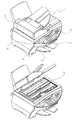
図1は、本発明の実施の形態に係るMFP1の概観斜視図である。なお、このMFP1は、ホストコンピュータ(PC)からデータを受信して印刷する通常のPCプリンタとしての機能、スキャナとしての機能を有している。またMFP単体で動作する機能として、スキャナで読取った画像をプリンタで印刷するコピー機能を有している。さらにはメモリカードなどの記憶媒体に記憶されている画像データを直接読取って印刷する機能や、デジタルカメラからの画像データを受信して印刷する機能を備えている。
FIG. 1 is a schematic perspective view of
図1のように、MFP1はフラットベッドスキャナなどの読取装置34、インクジェット方式や電子写真方式などによる印刷装置33、およびLCD等の表示パネル39や各種キースイッチ等を備える操作部35により構成されている。コピー動作時は、原稿台に置いた原稿を読取って得られた画像データをMFP内部でデータ処理し、印刷装置33で印刷する。
As shown in FIG. 1, the
読取装置34はCCD、密着型イメージセンサ(CIS)等のセンサを備えており、原稿画像を読取ると、赤(R)、緑(G)および青(B)色のアナログ輝度データを出力する。なお、後述のADF31を備えれば、連続で原稿を読取る事ができ、更に簡便である。またMFP1は不図示の駆動部を備え、給排紙ローラを駆動するためのステッピングモータ、モータの駆動力を伝達するギヤなどから構成され、上述した印刷装置33や読取装置34を使用する際に動作する。
The
操作部35が有するキースイッチとしては、記憶媒体に記憶された画像データを選択し、記録をスタートするためにフォトダイレクトプリントスタートキー、オーダーシートをプリントさせるキー、原稿を読取らすキーがある。加えて、モノクロコピー時やカラーコピー時におけるコピースタートキー、コピー解像度や画質などのモードを指定するモードキー、コピー動作などを停止するためのストップキー、並びに、コピー数を入力するテンキーや登録キーなどがある。また、MFP1の背面にはPCと通信するためのUSBポート(不図示)が設けられ、PCとの通信が行われる。
The key switch of the
MFP1は上記の構成に加え、各種メモリカードが挿入されるカードスロット42やデジタルカメラが接続されるカメラポート43を有する。さらに、自動で原稿を原稿台にセットするためのオートドキュメントフィーダ(以下ADF)31を有する。更にMFPは、不図示の画像処理装置が制御部として備えられており、操作部35が操作されるとユーザによる指示が制御部に入力され、入力した指示に基づく制御部の制御により各種の装置が動作する。またPC、メモリカード、デジタルカメラとのデータ通信も制御部による制御に基づき行われる。
In addition to the above configuration, the
図2には制御部の構成を示すブロック図である。 FIG. 2 is a block diagram showing the configuration of the control unit.
指示入力部15は、操作部35で行われた操作に応じた信号が入力される。
The
CPU11は、指示入力部15への入力に従い、ROM16に記憶されたプログラムを実行することで、制御部が備える各機能を制御する。
The CPU 11 controls each function provided in the control unit by executing a program stored in the ROM 16 in accordance with an input to the
ROM16にはオペレーティングシステムも格納されており、これによりプログラムの実行単位であるタスクを複数生成することができる。CPU11はそれぞれのプログラムを時分割して実行することができるため、複数のプログラムをあたかも同時に処理するように実行できる。また、オペレーティングシステムは、メッセージやイベントなどの手段を提供してタスク間の同期を行うことができ、これによりCPU11を効率的に使用できるようになっている。 An operating system is also stored in the ROM 16, whereby a plurality of tasks that are program execution units can be generated. Since the CPU 11 can execute each program in a time-sharing manner, it can execute a plurality of programs as if they were processed simultaneously. Further, the operating system can provide means such as a message and an event to synchronize between tasks, so that the CPU 11 can be used efficiently.
画像処理部12においては、後述する画像解析、変換特性の算出、輝度信号(RGB)から濃度信号(CMYK)への変換、スケーリング、ガンマ変換、誤差拡散等画像処理が行われ、それによって得られるデータは、RAM17に格納される。このようにRAM17に格納されたデータが記録するのに必要な所定量に達すると、図1の印刷装置33により記録動作が実行される。また不揮発性RAM18は、バッテリバックアップされたSRAMなどで、画像処理装置に固有のデータなどを記憶する。
In the image processing unit 12, image processing, which will be described later, calculation of conversion characteristics, conversion from a luminance signal (RGB) to a density signal (CMYK), scaling, gamma conversion, error diffusion, and other image processing are performed, and thus obtained. Data is stored in the
印刷制御部13は印刷装置33を制御し、CPU11の制御により、RAM17に格納されている記録データを読み出して印刷装置33に出力して印刷を行わせる。また読取制御部14は読取装置34を制御し、センサを駆動させて画像を読取り、読取装置34から入力した画像データをRAM17に格納する。
The print control unit 13 controls the printing device 33, and under the control of the CPU 11, the recording data stored in the
カードインターフェイス22は、カードスロット42に挿入されたメモリカードに記録された画像データを、指示入力部15へ入力されたユーザの指示に従い読み込み、RAM17に格納する。また指示入力部15への入力に従って、画像データをメモリカードに書き込む。なお、カードインターフェイス22を介して読み込まれた画像データの色空間は、必要ならば、画像処理部12により、デジタルカメラの色空間(例えばYCbCr)から標準的なRGB色空間(例えばNTSC−RGBやsRGB)に変換される。カメラインターフェイス23は、デジタルカメラが備えるメモリカードなどに記録された画像データを、指示入力部15への入力に従いカメラポート43を介して読み込み、RAM17に格納する。PCインターフェイス24はUSBポートを介してPCから入力された画像をRAM17に格納する。これらのインターフェイスで読み込まれた画像データは、有効な画素数への解像度変換など、アプリケーションに必要な様々な処理が必要に応じて施される。
The card interface 22 reads the image data recorded on the memory card inserted into the
表示制御部19は例えばLCDドライバ等であり、CPU11の制御に基づき画像を表示パネル39に表示させる。またメモリカードに記録されていた画像データのサムネイルを表示する。センサ部20は、記録紙幅センサ、記録紙有無センサ、原稿幅センサ、原稿有無センサおよび記録媒体検知センサなど各種のセンサの入力をCPU11に通知する。CPU11は、これらの情報に基づき、原稿および記録紙の状態を検知する。
The
JPEGエンコーダ25はCPU11の指示に基づき、RAM17に格納されているビットマップ形式のデータを圧縮符号化であるJPEG形式に変換した後、RAM17に格納する。JPEGデコーダ26はCPU11の指示に基づき、RAM17に格納されているJPEGデータをビットマップ形式のデータに変換した後、RAM17に格納する。
Based on an instruction from the CPU 11, the
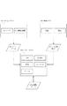
図3は本実施例における制御プログラムの構成図である。 FIG. 3 is a configuration diagram of a control program in the present embodiment.
この図のスキャンタスク801、解析タスク802、プリントタスク803の3つのタスクがそれぞれ、オペレーティングシステムの提供する手段によって同期を取りながら動作する。 The three tasks, a scan task 801, an analysis task 802, and a print task 803 in this figure, operate while being synchronized by means provided by the operating system.
スキャンタスク801は入力画像処理とエンコード処理を実施し、またクロップ位置情報を参照してJPEGバンド画像を作成するプログラムである。解析タスク802はスキャンタスクによって読み込まれた画像を変倍し画像の解析を行ってクロップ位置情報を作成するプログラムである。プリントタスク803はJPEGバンド画像とクロップ位置情報を参照して、JPEG画像データを作成するプログラムである。またプリントタスク803には回転、切出し、連結、エンコード、デコードの各処理が含まれる。これらスキャンタスク801、解析タスク802、プリントタスク803の各動作の詳細は後述する。 A scan task 801 is a program that performs input image processing and encoding processing, and creates a JPEG band image by referring to crop position information. An analysis task 802 is a program that creates crop position information by scaling the image read by the scan task and analyzing the image. A print task 803 is a program for creating JPEG image data with reference to a JPEG band image and crop position information. The print task 803 includes rotation, cropping, concatenation, encoding, and decoding processes. Details of the operations of the scan task 801, analysis task 802, and print task 803 will be described later.
なお本発明の実施の形態はこれに限定されるものではなく、他の様々な実行単位に分割したり、別の手段を用いて同期をとったりしてもよい。また制御の一部または全てをハードウェアで構成してもよい。 The embodiment of the present invention is not limited to this, and may be divided into other various execution units or may be synchronized using another means. Moreover, you may comprise a part or all of control by hardware.
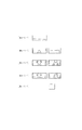
次に、読取装置がフラットベッドスキャナの場合のマルチクロップについて説明する。 Next, multi-crop when the reading device is a flatbed scanner will be described.
図4は、本実施例のフラットベッドスキャナによる読取動作を示す図であり、図4(a)は、実施例1でユーザが原稿台に原稿をセットした様子をあらわしている。ここで、原稿台の上には原稿601、602、603が重ならないように隙間をあけて置かれている。原稿の大きさはそれぞれ異なっていても良い。また原稿は原稿台に対して傾いていてもよい。ユーザは原稿台の上に原稿を置いた後、表示パネル39の表示に従って操作部35を操作すると読取動作を開始する。すると読取られた画像全てが一度に制御部に入力されるのではなく、バンド毎に入力される。
FIG. 4 is a diagram showing a reading operation by the flatbed scanner of the present embodiment, and FIG. 4A shows a state in which the user sets a document on the document table in the first embodiment. Here, the
図4(b)は原稿台全面を読取った画像をバンド毎に分割した様子を示している。詳細は図8のSTEP101で後述する。
FIG. 4B shows a state in which an image obtained by reading the entire surface of the document table is divided for each band. Details will be described later in
この図においては、1バンドに16ラインが含まれており、実際には各バンドの短辺は長辺よりも十分に短いが、説明のため実際よりもバンドの短辺を大きく表現している。またRAM17にはバンド画像単位で記憶されるため、1バンドに含まれるライン数はRAMのサイズや画像処理部12の一度に処理できるデータ量によって決まり、実際には8ラインないし32ライン程度が適当と考えられる。この場合、600dpiの解像度で読み込みすると、1バンドの幅はおよそ0.34ミリメートルないし1.35ミリメートルとなる。これは原稿台に置かれる通常の原稿の大きさと比較すれば十分に小さいので、原稿のデータは複数のバンドに分割される。
In this figure, 16 bands are included in one band, and the short side of each band is actually sufficiently shorter than the long side, but the short side of the band is expressed larger than the actual for the sake of explanation. . Since the
図4(c)は後述の図3のスキャンタスク801で扱うバンド単位の画像データを表した模式図である。なお、このバンド単位の画像データをここではバンド画像という。 FIG. 4C is a schematic diagram showing band-unit image data handled by a scan task 801 in FIG. 3 to be described later. This band-unit image data is referred to as a band image here.
バンド画像610ないし613は、後述の図8のSTEP101において読取制御部14に入力され、RAM17に記憶される画像データである。なお本実施例のRAM17はフレームメモリではないので、原稿台全面を読取った画像を構成する全てのバンドを記憶することはできない。したがってRAM17の所定のメモリ領域が埋まった場合、バンド画像は上書きされて記憶されることになる。また図の各画素に付された座標は、解析タスク802で検出された各点の座標であり、図における左上の画素の座標を(0、0)としたときの座標である。この座標がクロップ位置情報となる。
The
図5はエンコード対象領域を示す図である。 FIG. 5 is a diagram showing an encoding target area.
図5(a)は解析タスク802の検出結果を示す表であり、図4(c)に示した座標に対応して、各バンド内に含まれる画像の位置を示すクロップ位置情報が記載されている。例えばバンド番号0には4つの点で囲まれる1つの閉領域が存在し、バンド番号1には4つの点で囲まれる2つの閉領域が存在することを表している。またバンド番号3には4つの点で囲まれる1つの閉領域と、5つの点で囲まれる一つの閉領域が含まれることを表している。さらにバンド番号4には3つの点で囲まれる一つの閉領域が含まれることを表している。加えて、このような閉領域にそれぞれに対応したIDが付されている。
FIG. 5A is a table showing the detection result of the analysis task 802, in which crop position information indicating the position of the image included in each band is described corresponding to the coordinates shown in FIG. 4C. Yes. For example,
図5(b)は各バンドのJPEGエンコード対象領域を示す表である。表の各行は各バンドでのエンコード対象となる領域のX座標と、その領域の幅であり、これらの領域は図5(a)で示した各バンドの閉領域を含むように設定される。 FIG. 5B is a table showing the JPEG encoding target area of each band. Each row of the table is the X coordinate of the region to be encoded in each band and the width of the region, and these regions are set so as to include the closed region of each band shown in FIG.
ただし、このようなエンコード対象領域は各種の制限の下に設定されており、結果として対象領域とクロップ位置情報の示す領域は一致しないことがある。例えば本実施例において、画像はJPEG形式にエンコードされるため、JPEGのエンコード単位であるMinimum Coded Unit(以下MCUという)の倍数になるようにエンコード対象領域が選択される。なおJPEGのMCUとしては幅8ピクセル高さ8ピクセルが代表的である。 However, such an encoding target area is set under various restrictions, and as a result, the target area may not match the area indicated by the crop position information. For example, in this embodiment, since the image is encoded in the JPEG format, the encoding target area is selected so as to be a multiple of the Minimum Coded Unit (hereinafter referred to as MCU) which is a JPEG encoding unit. A typical JPEG MCU is 8 pixels wide and 8 pixels high.
またJPEGエンコーダによっては、読取制御部14が入力した画像データが格納されているRAM17のアドレスに制限がある場合がある。例えば入力する画像データは32バイトの倍数アドレスから始まっていなければならない、といった制約がある場合、この制約を満たすようにJPEGエンコード領域を選択する。この場合、入力する画像データがRGB各8ビットの形式である場合、1ピクセルあたり3バイトの情報量が必要なので、3と32の最小公倍数である96バイトの倍数で一つのラインが構成されることが望ましい。従って、JPEGエンコードの開始位置のX座標と、エンコード対象のX座標方向の幅は32ピクセルの倍数で構成されるとその後の処理が簡単になる。
Depending on the JPEG encoder, there may be a limitation on the address of the
また後述するように、読取ノイズやエッジ検出処理、その他の理由によって、各バンドのクロップ位置情報に含まれる閉領域を連結した場合に、四辺形にならない場合がある。この場合、四辺形になるように画像領域を調整するが、JPEGエンコード領域を大きめに取っておくことで、調整の範囲をあらかじめ確保しておくこともできる。 As will be described later, when the closed regions included in the crop position information of each band are connected due to reading noise, edge detection processing, or other reasons, the quadrilateral may not be formed. In this case, the image area is adjusted so as to form a quadrilateral, but the adjustment range can be secured in advance by keeping a large JPEG encoding area.
本実施例ではJPEGエンコードの開始位置のX座標と、エンコード対象領域のX座標方向の幅が32ピクセルの倍数となる。なお、ここでは上述の理由により、領域が若干大きめになるよう求める。この領域は、各バンドで検出された図5(a)の各点の座標のX座標から次の計算で求めることができる。
(JPEGエンコード領域の開始X座標)=Max([バンド内で検出された各点のうち最小のX座標/32]×32−32、0)・・・・・・式(1)
(JPEGエンコード領域の終了X座標)=Min([((バンド内で検出された各点の最大のX座標+31)/32)]×32+31、1ラインのピクセル数−1)・・・・・・式(2)
なお[]はガウス記号であり、囲まれた値を超えない最大の整数をあらわす。この式(1)で求められたX座標から式(2)で求められたX座標までがJPEGエンコーダの対象領域となる。なお、本実施例では符号化形式としてJPEGを例に挙げるが、JPEG以外の符号化形式を採用しても構わない。
In this embodiment, the X coordinate of the start position of JPEG encoding and the width of the encoding target area in the X coordinate direction are multiples of 32 pixels. Here, for the reason described above, the area is required to be slightly larger. This region can be obtained by the following calculation from the X coordinate of the coordinates of each point in FIG. 5A detected in each band.
(Start X-coordinate of JPEG encoding area) = Max ([Minimum X-coordinate / 32 of each point detected in band / 32] × 32−32, 0) (1)
(End X coordinate of JPEG encoded area) = Min ([((maximum X coordinate of each point detected in the band + 31) / 32)] × 32 + 31, number of pixels in one line−1)・ Formula (2)
Note that [] is a Gaussian symbol and represents the maximum integer that does not exceed the enclosed value. The target area of the JPEG encoder is the range from the X coordinate obtained by the equation (1) to the X coordinate obtained by the equation (2). In this embodiment, JPEG is exemplified as an encoding format, but an encoding format other than JPEG may be adopted.
図6はJPEGエンコード対象領域の一例を示す図であり、図4に示した画像に対してクロップ処理を行うと、このように各バンド画像のうち原稿台に置かれた原稿を含む画像をエンコードの対象とすることができる。なおここでは、バンド画像のうち、このエンコードされる画像を部分画像と呼ぶ。 FIG. 6 is a diagram showing an example of the JPEG encoding target area. When the cropping process is performed on the image shown in FIG. 4, an image including a document placed on the document table is encoded among the band images. Can be the target of. Here, of the band images, this encoded image is called a partial image.
また図7は原稿ごとに設定されたJPEGエンコード対象領域の一例を示す図である。このように1つのバンド内においても原稿に対応した領域ごとにJPEGエンコードを行うように設定すれば、JPEGエンコードした結果を記憶するのに必要なメモリ容量をより削減することができる。 FIG. 7 shows an example of the JPEG encoding target area set for each document. Thus, if JPEG encoding is set to be performed for each area corresponding to a document even within one band, the memory capacity required to store the result of JPEG encoding can be further reduced.
図8は、スキャンタスクの動作を説明するためのフローチャートである。 FIG. 8 is a flowchart for explaining the operation of the scan task.
スキャンタスク801は、MFPに必要な画像処理のうち、スキャナ部が読取った画像データに対する画像処理を実行する。 A scan task 801 executes image processing on image data read by the scanner unit among image processing necessary for the MFP.
STEP101では、読取制御部14に入力された16ライン分の画像データ、つまりはバンド画像を取得すると、一時的に記憶させるためのバッファメモリ領域としてRAM17に記憶して、STEP102に進む。
In
STEP102では、STEP101でバンド画像を取得したことを示すメッセージを解析タスクに送信して、STEP103に進む。
In
STEP103では、STEP101で取得した画像データの入力画像処理を行う。入力画像処理には、ガンマ変換、スキャナのデバイス色空間から標準色空間へのルックアップテーブルの適用、下地除去処理、などがある。これらの画像処理は画像処理部12で行われる。
In STEP 103, input image processing of the image data acquired in
なおSTEP102において、STEP101でバンド画像を解析タスクに送信する代わりに、STEP103で画像処理されたバンド画像を送信してもよい。しかし、ガンマ変換や下地除去処理を行った後の画像に対しては、図9のSTEP202で後述する解析タスクでのクロップ位置検出処理が難しくなる。そのため、解析タスクに送信する画像はSTEP103で画像処理をしたバンド画像ではなく、STEP101で取得したバンド画像であることが望ましい。
In
次にSTEP104では、解析タスクからJPEGエンコード対象領域を示すメッセージを受信する。メッセージを受信したら、STEP105に進む。
Next, in
STEP105では、STEP104で受信したメッセージに従って、STEP103で画像処理を行ったバンド画像のJPEGエンコーダ対象領域を、JPEGエンコーダ25でエンコードしてJPEGバンド画像を生成する。さらに生成したJPEGバンド画像をRAM17に記憶させる記憶制御を行う。
In STEP 105, in accordance with the message received in
なお、図8の説明では、STEP101での画像と、STEP105での画像は、共にRAM17に記憶されるが、それぞれ別のメモリに記憶するものであってもよい。例えばSTEP101では画像を一時的に記憶する領域であるバッファメモリ領域に記憶させれば良く、その記憶先は問わない。
In the description of FIG. 8, the image at
図5(b)によればバンド0に対応するエンコード開始位置は448、終了位置は2079であるので、X座標が448から2079の1632ピクセル幅の領域をJPEGエンコーダ25でエンコードする。なお、エンコードされない部分に関してはRAM17から削除される。またバンド画像内にJPEGエンコード対象領域がない、つまりは原稿に対応する画像を含まない場合はエンコードを行わない。このようにJPEGバンド画像を生成したら、STEP106に進む。
According to FIG. 5B, since the encoding start position corresponding to the
STEP106では、原稿台全面をスキャンしたかどうかを判定する。 In STEP 106, it is determined whether the entire surface of the document table has been scanned.
もし原稿台全面をスキャンし終えていたら、スキャン終了である。スキャンの終了処理には、スキャナヘッドをホームポジションに戻すなど、機構上必要な処理が含まれる。STEP106で、もし原稿台全面をスキャンし終えていないと判断されたなら、STEP101に戻り、次のバンドをスキャンする。 If the entire document table has been scanned, the scanning is finished. The scanning end processing includes processing necessary for the mechanism such as returning the scanner head to the home position. If it is determined in STEP 106 that the entire document table has not been scanned, the process returns to STEP 101 to scan the next band.
以上のSTEP101からSTEP106がスキャンタスク801により繰り返し処理されることによって、バンド毎に順次読取りが行われ、JPEGバンド画像がRAM17に順次記憶される。したがってこの処理により、原稿台に置かれた原稿の部分を含むJPEGバンド画像を生成することができる。
The
このように原稿に対応する画像を含まないバンドや、バンド内の原稿を含まない部分に関してはエンコードしないことで、原稿台全面を読取ったバンド全てをエンコードする場合と比較して必要なRAM使用量が少なくなるという効果がある。またJPEGで圧縮することによって、RGBのデータをそのままRAMに格納する場合と比較して、必要なRAM使用量が少なくなるといった効果がある。 In this way, a band that does not include an image corresponding to a document or a portion that does not include a document in a band is not encoded, so that the required RAM usage is required compared to encoding all the bands that have been read over the entire surface of the document table. Is effective. Further, by compressing with JPEG, there is an effect that a required amount of RAM is reduced as compared with the case where RGB data is stored in the RAM as it is.
なお、このフローチャートではSTEP103でガンマ変換をかけた後にS105でJPEGエンコードを行っている。これはJPEGエンコードを行った後にガンマ変換をかけると、階調性が失われてしまうからである。というのも読取制御部14で入力した画像は1画素のRGB各色あたり8ビット(256階調)より多い階調を持っているが、JPEGではフォーマットの仕様上、YCbCrの各色256階調より多い階調は失われてしまう。よってJPEGエンコードを行うことでYCbCr256階調にしてしまい、256階調にした後でガンマ変換をかけると、それと見てわかるほど階調性が失われてしまうことがある。
In this flowchart, JPEG encoding is performed in S105 after performing gamma conversion in STEP103. This is because gradation is lost when gamma conversion is performed after JPEG encoding. This is because the image input by the
したがってエンコードするデータをSTEP103で画像処理を施した後のデータとすることで、JPEG化による階調性の劣化を抑えることができる。 Therefore, by setting the data to be encoded as data after image processing in STEP 103, it is possible to suppress deterioration in gradation due to JPEG conversion.
図9は、解析タスクの動作を説明するためのフローチャートである。 FIG. 9 is a flowchart for explaining the operation of the analysis task.
STEP201で、スキャンタスクがSTEP102で送信したメッセージを受信する。このように解析タスクは、スキャンタスクがSTEP102で送信したメッセージを受信してから次のステップに進むことで、スキャンタスクの処理の進み具合に同期して解析タスクの処理を進めることができる。
In STEP 201, the message transmitted by the scan task in
つまり解析タスクは、メッセージが受信できるまで待ちつづけ、メッセージを受信したらSTEP202に進む。 That is, the analysis task continues to wait until a message can be received, and proceeds to STEP 202 when a message is received.
STEP202では、スキャンタスクがSTEP101でRAM17に保存した画像データから、クロップ位置情報を生成する。まず解析タスクは、スキャンタスクがSTEP101でRAM17に保存した画像データの解像度を変換し、第二解像度の画像を作成してRAM17に保存する。スキャンタスクが作成する画像解像度は600dpi程度であるので、これを150dpi程度に小さくすることにより、CPU11が処理する画素数を少なくできる。第二の解像度を小さくすることで、解析結果の精度が低下するといった問題はあるものの、結果として解析タスクが画像解析に要する時間を短縮することができる。
In
またこの第二の解像度によって解析タスクが画像解析に要する時間を調整することができる。読取装置の動作が速いモードではより小さな解像度(例えば100dpi)に、読取装置の遅いモードではより大きな解像度(例えば300dpi)に指定することで、読取装置に合わせた処理速度に調整することができる。 Further, the time required for the image analysis by the analysis task can be adjusted by the second resolution. By specifying a smaller resolution (for example, 100 dpi) in a mode in which the operation of the reading apparatus is fast, and a larger resolution (for example, 300 dpi) in a mode in which the reading apparatus is slow, it is possible to adjust the processing speed according to the reading apparatus.
このように解像度が変換され縮小された画像に対してエッジ検出処理を行ったあと2値化し、ラベリング処理を実行することでバンド画像のうち、原稿に対応する領域を検出する。なおエッジ検出処理には、ソーベルフィルタなど既知の様々なフィルタが利用可能である。さらにラベリング処理に加えて、濃度判定を行うことにより、原稿台の圧板の色が白であることを利用して、原稿領域と原稿領域外(すなわち圧板)を判別してクロップ位置情報を得ることができる。 In this way, the edge detection process is performed on the image whose resolution has been converted and reduced, and then binarization is performed, and the labeling process is executed to detect an area corresponding to the original in the band image. For the edge detection process, various known filters such as a Sobel filter can be used. Further, in addition to the labeling process, by determining the density, it is possible to obtain the crop position information by discriminating between the document area and the outside of the document area (that is, the pressure plate) using the white color of the platen on the platen. Can do.
またSTEP202では前述した式(1)、式(2)を用いてクロップ位置情報からJPEGエンコード対象領域を求める。このようにクロップ位置情報を生成したら、STEP203に進む。
In
STEP203では、スキャンタスクへJPEGエンコード対象領域を示す情報を含むメッセージを送信する。メッセージを送信したら、STEP204へ進む。
In
STEP204では、画像が完成したかを判定する。この画像が完成したか否かの判定は、クロップ位置情報が示す座標のうちバンドの下端に届いていない座標があれば、連結した閉領域の終わりと判断できる。例えば図4(c)に示す第3バンドの画像領域では、最も大きなY座標値が13であることから一つの画像が完成したとみなすことができる。また最も大きなY座標値が15である場合でも、次のバンドの判定時に連結する画像領域が存在しない場合にも一つの連結した閉領域の終わりと判断できる。このようにバンド画像の中に原稿画像の端点(原稿の角)が含まれ、その端点が原稿の下端である場合に原稿が完成したと判断することができる。
In
画像が完成したと判断されれば、STEP205へ進む。また画像が完成したと判断されなければSTEP201へ戻り、スキャンタスクが次のバンドを読取ってメッセージを送信するのを待つ。 If it is determined that the image is completed, the process proceeds to STEP 205. If it is not determined that the image is completed, the process returns to STEP 201 and waits for the scan task to read the next band and send a message.
STEP205では、クロップ位置情報を含むメッセージをプリントタスクへ送信して、JPEGバンド画像とクロップ位置情報とに基づいて印刷することを指示する。メッセージを送信したらSTEP201に戻る。
In
図10は、プリントタスクの動作を説明するためのフローチャートである。 FIG. 10 is a flowchart for explaining the operation of the print task.
STEP301では、解析タスクがSTEP205で送信したメッセージを受信する。このメッセージを受信したということは、RAM17に原稿に対応する画像のJPEGバンド画像が記憶されており、この情報をもとに原稿に対応する画像を切出すことが可能であるということである。
In
またSTEP301では、隣接するJPEGバンド画像に含まれる原稿に対応する画像の一部を一つの領域として連結する。連結する際には解析タスクから受信したクロップ位置情報に基づき連結する領域を検出する。例えば、図5(a)において、ID=0の行にあるバンド番号0の線分(505,15),(2021,15)と、ID=1の行にあるバンド番号1の線分(2021,0)、(505,0)は1517ピクセルにわたって接していることがわかる。したがってID=0とID=1の領域を一つのまとまった領域と判断することができる。同様に、ID=0とID=1とID=2とID=3が一つの連結した領域と判断できる。同様にID=2とID=4とID=6とID=7が一つの連結した領域と判断できる。
In
さらに連結した領域が、長方形となるように、座標の調整をおこなってもよい。連結した領域は、そのままでは連結した多角形であり、長方形とは限らないため、その後の印刷や表示などの処理に不向きである。画像領域情報の座標力最小二乗法などを用いて、一つの直線を近似する方法が考えられる。このように、メッセージを受信して複数の領域を連結するとSTEP302に進む。 Further, the coordinates may be adjusted so that the connected region becomes a rectangle. The connected region is a connected polygon as it is, and is not necessarily a rectangle, and is not suitable for subsequent processing such as printing and display. A method of approximating one straight line using the coordinate force least square method of image area information is conceivable. In this way, when a message is received and a plurality of areas are connected, the process proceeds to STEP 302.
STEP302では、STEP301で連結された領域を含む各バンドのJPEGバンド画像をデコードし、RGB値を持つビットマップデータに変換してRAM17に記憶する。なおこのとき、後述のSTEP304でエンコードに必要な画素を計算して、必要なMCU分だけデコードするようにすると、RAM17のメモリ使用量が少なくてすむ。
In
STEP303では、STEP302でデコードされたRGBデータから、STEP301で連結された長方形領域に対応する部分を切出して回転する。回転時の補間方法としては、最近傍法や線形補間法などを使うことができる。
In
STEP304では、STEP303で回転された画像をJPEG形式にエンコードし、連結した長方形領域に対応するJPEG画像データを生成する。次にSTEP305へ進み、STEP304で生成したJPEG画像データを印刷する。印刷が終了したら、処理を終了する。
In
なお印刷対象となるJPEG画像データは原稿一枚分に相当するJPEG画像データであるため、印刷の処理は、いわゆるカードダイレクトやカメラダイレクト機能で一般に実施されているものと同じである。 Since the JPEG image data to be printed is JPEG image data corresponding to one original, the printing process is the same as that generally performed with a so-called card direct or camera direct function.
以上、図10に示した処理により、RAM17に記憶された複数のJPEGバンド画像から、原稿に相当するJPEG画像データを切出して印刷することができる。なお、解析タスクにおいて原稿に対応する画像が完成したと判断され(図9のSTEP204でYES)、解析タスクからプリントタスクにメッセージが送信されると再び図10で示した処理が行われる。
As described above, JPEG image data corresponding to a document can be cut out and printed from a plurality of JPEG band images stored in the
以上の実施例によれば、原稿台全面を読取った画像をバンド画像毎に記憶して、そのバンド画像内で原稿領域を検出する。また複数バンドを記憶した結果、記憶した複数バンドが原稿画像を含む場合、原稿画像を切出す。 According to the above embodiment, an image obtained by reading the entire surface of the document table is stored for each band image, and the document region is detected in the band image. Further, as a result of storing a plurality of bands, when the stored plurality of bands include a document image, the document image is cut out.
これにより、原稿領域を含まないバンド画像、またはバンド画像内で原稿領域ではない領域を記憶する必要がなくなるので、1回の読取動作によるクロップ処理を、従来と比較してメモリ容量を抑えて行うことができる。したがってフレームメモリを有さない装置においても2回以上スキャンする必要がなくなるために、動作完了までの時間が短くなるといった効果がある。また2回以上スキャンすることが原因でおこる、ずれた位置を切出してしまうという問題がなくなるといった効果がある。さらに、バンド単位でスキャンと解析処理をするので、スキャンが完了しなくとも読取った画像が完成したかを判定して順次印刷を開始できる。そのため、動作完了までの時間が短くなるといった効果がある。 As a result, there is no need to store a band image that does not include a document area, or a region that is not a document area in the band image. Therefore, crop processing by a single reading operation is performed with a reduced memory capacity compared to the conventional case. be able to. Therefore, even in an apparatus that does not have a frame memory, it is not necessary to scan twice or more, so that the time until the operation is completed is shortened. Further, there is an effect that the problem of cutting out a shifted position caused by scanning twice or more is eliminated. Furthermore, since scanning and analysis processing are performed in band units, printing can be started sequentially by determining whether the read image is completed even if scanning is not completed. Therefore, there is an effect that the time until the operation is completed is shortened.
加えて、以上の実施例に拠れば、中間のデータをJPEGバンドとして保存するので、原稿台全面を覆うような原稿を入力した場合においても、メモリ削減効果が得られるといった効果がある。 In addition, according to the above embodiment, since intermediate data is stored as a JPEG band, even when a document covering the entire surface of the document table is input, there is an effect that a memory reduction effect can be obtained.
また、以上の実施例では本発明のクロップ処理で得られたJPEG画像データを印刷用途に使用する場合を説明したが、本発明の適用はこれに限られるものではない。例えば、カードインターフェイス22を介してメモリカードにJPEG画像データを保存したり、PCインターフェイス24を介してPCへ転送したりすることにも利用可能である。 In the above embodiments, the case where the JPEG image data obtained by the crop processing of the present invention is used for printing has been described. However, the application of the present invention is not limited to this. For example, JPEG image data can be stored in a memory card via the card interface 22 or transferred to a PC via the PC interface 24.
以上の実施例では複数の原稿が原稿台に置かれた場合のマルチクロップを例に説明したが、本発明はこれに限るものではなく、原稿が1枚であるときのクロップ処理でもよい。さらに原稿が原稿台に載置されて読取られる場合だけでなく、ADFにより読取られて得られた画像にクロック処理を行う場合であってもよい。 In the above embodiment, the multi-crop when a plurality of documents are placed on the document table has been described as an example. However, the present invention is not limited to this, and may be a crop process when there is only one document. Furthermore, not only when the original is placed on the original table and read, but also when the clock processing is performed on the image obtained by the ADF.
通常ではADFには積み重ねられた原稿を一枚ずつ紙送りしながら読取るため、ある時点で読取られている原稿は一枚だけである。またADFでは、一度紙の端まで読取りした原稿は読取りローラから外れてしまうため、もう一度原稿の最初から戻って2度目のスキャンができない構造となっている。したがって、ADFを使用して原稿を連続して読取る場合、2回の読取動作が必要なクロップ処理は行えないため、ADFはあるがフレームメモリを有さない装置において本発明は特に有効である。 Normally, the ADF reads the stacked documents while feeding them one by one, so that only one document is read at a certain time. In the ADF, since the document once read to the edge of the paper is removed from the reading roller, the document cannot be scanned a second time by returning from the beginning of the document again. Therefore, when the document is continuously read using the ADF, the cropping process that requires two reading operations cannot be performed. Therefore, the present invention is particularly effective in an apparatus that has an ADF but does not have a frame memory.
他にも、本発明によりADFにより読取られた画像の傾き補正を行うことができる。つまり、ADFには原稿が傾かないように原稿給紙ガイドが設けられているが、ユーザが原稿給紙ガイドを正しく設定しなかったなどの原因で、まっすぐに原稿が給紙されず、傾いて読取られてしまう場合がある。このような場合に、本発明のクロップ処理を用いて読取られた画像から原稿に対応する領域を切出して、傾きを補正することができる。 In addition, it is possible to correct the inclination of the image read by the ADF according to the present invention. In other words, the ADF is provided with a document feeding guide so that the document does not tilt, but the document is not fed straight and tilted because the user did not set the document feeding guide correctly. It may be read. In such a case, it is possible to correct the inclination by cutting out an area corresponding to the original from the image read using the crop processing of the present invention.
また本発明の目的は、前述した実施形態の制御部の機能を実現するプログラムコードを記録した記録媒体をシステムあるいは装置に供給することによっても達成される。その場合、システムあるいは装置のコンピュータ(またはCPUまたはMPU)がそのプログラムコードを読出して実行することによって実現できる。この場合、記録媒体から読み出されたプログラムコードが前述した実施形態の機能を実現することとなり、そのプログラムコードを記憶した記録媒体、及びそのプログラムコード自体は本発明を構成することになる。 The object of the present invention can also be achieved by supplying a recording medium recording a program code for realizing the function of the control unit of the above-described embodiment to a system or apparatus. In that case, it can be realized by the computer (or CPU or MPU) of the system or apparatus reading and executing the program code. In this case, the program code read from the recording medium realizes the functions of the above-described embodiment, and the recording medium storing the program code and the program code itself constitute the present invention.
プログラムコードを供給するための記録媒体としては、例えば、ハードディスク、CD−ROM、CD−R、不揮発性のメモリカード、ROM、DVDなどがある。 Examples of the recording medium for supplying the program code include a hard disk, a CD-ROM, a CD-R, a nonvolatile memory card, a ROM, and a DVD.
1 MFP
31 オートドキュメントフィーダ
33 印刷装置
34 読取装置
35 操作部
11 CPU
12 画像処理部
13 印刷制御部
14 読取制御部
15 指示入力部
16 ROM
17 RAM
18 不揮発性RAM
19 表示制御部
20 センサ部
25 JPEGエンコーダ
26 JPEGデコーダ
1 MFP
31 Auto Document Feeder 33
12 Image processing unit 13
17 RAM
18 Nonvolatile RAM
19
Claims (13)
画像を記憶するためのメモリと、
読取装置が原稿を読取って得られた画像をバンド画像単位で入力する入力手段と、
前記入力手段により入力された前記バンド画像を解析して、前記バンド画像のうち前記原稿に対応する領域を検出する検出手段と、
前記バンド画像のうち前記検出手段により検出された領域を含む部分画像を前記メモリに記憶させる記憶制御手段と、
前記メモリに記憶された部分画像から前記原稿に対応する画像を切出す切出手段と、
を有することを特徴とする画像処理装置。 An image processing apparatus that cuts out an image corresponding to the document from an image obtained by reading the document by the reading device,
A memory for storing images;
An input means for inputting an image obtained by reading the document by the reading device in units of band images;
Analyzing the band image input by the input means, and detecting a region corresponding to the document in the band image;
Storage control means for storing a partial image including an area detected by the detection means in the band image in the memory;
Cutting means for cutting out an image corresponding to the document from the partial image stored in the memory;
An image processing apparatus comprising:
読取装置が原稿を読取って得られた画像をバンド画像単位で入力する入力工程と、
前記入力工程で入力された前記バンド画像を解析して、前記バンド画像のうち前記原稿に対応する領域を検出する検出工程と、
前記バンド画像のうち前記検出工程で検出された領域を含む部分画像をメモリに記憶させる記憶制御工程と、
前記メモリに記憶された部分画像から前記原稿に対応する画像を切出す切出工程と、
を有することを特徴とする画像処理方法。 An image processing method for cutting out an image corresponding to an original from an image obtained by reading the original with a reading device,
An input process in which an image obtained by reading a document by a reading device is input in band image units;
Analyzing the band image input in the input step, and detecting a region corresponding to the document in the band image;
A storage control step of storing a partial image including the region detected in the detection step in the band image in a memory;
A cutting step of cutting out an image corresponding to the document from the partial image stored in the memory;
An image processing method comprising:
Priority Applications (2)
| Application Number | Priority Date | Filing Date | Title |
|---|---|---|---|
| JP2008163636A JP4929237B2 (en) | 2008-06-23 | 2008-06-23 | Image processing apparatus and image processing method |
| US12/489,178 US8199357B2 (en) | 2008-06-23 | 2009-06-22 | Image processing apparatus and method detecting and storing areas within band images and cutting out an image from the resulting stored partial image |
Applications Claiming Priority (1)
| Application Number | Priority Date | Filing Date | Title |
|---|---|---|---|
| JP2008163636A JP4929237B2 (en) | 2008-06-23 | 2008-06-23 | Image processing apparatus and image processing method |
Publications (3)
| Publication Number | Publication Date |
|---|---|
| JP2010004476A true JP2010004476A (en) | 2010-01-07 |
| JP2010004476A5 JP2010004476A5 (en) | 2011-12-22 |
| JP4929237B2 JP4929237B2 (en) | 2012-05-09 |
Family
ID=41430954
Family Applications (1)
| Application Number | Title | Priority Date | Filing Date |
|---|---|---|---|
| JP2008163636A Expired - Fee Related JP4929237B2 (en) | 2008-06-23 | 2008-06-23 | Image processing apparatus and image processing method |
Country Status (2)
| Country | Link |
|---|---|
| US (1) | US8199357B2 (en) |
| JP (1) | JP4929237B2 (en) |
Cited By (6)
| Publication number | Priority date | Publication date | Assignee | Title |
|---|---|---|---|---|
| JP2012039494A (en) * | 2010-08-10 | 2012-02-23 | Fuji Xerox Co Ltd | Image processing apparatus, image processing system and program |
| JP2013031106A (en) * | 2011-07-29 | 2013-02-07 | Brother Ind Ltd | Image processor and computer program |
| JP2018121275A (en) * | 2017-01-27 | 2018-08-02 | 京セラドキュメントソリューションズ株式会社 | Display device and image reading apparatus |
| JP2020010287A (en) * | 2018-07-12 | 2020-01-16 | 京セラドキュメントソリューションズ株式会社 | Image processing apparatus and method for controlling image processing apparatus |
| JP2020141286A (en) * | 2019-02-28 | 2020-09-03 | ブラザー工業株式会社 | Image reading device |
| US11405510B2 (en) | 2020-08-19 | 2022-08-02 | Brother Kogyo Kabushiki Kaisha | Image reader determines if read image data of test pattern satisfies predetermined condition before resuming reading of test pattern |
Families Citing this family (5)
| Publication number | Priority date | Publication date | Assignee | Title |
|---|---|---|---|---|
| TWI395466B (en) * | 2010-08-13 | 2013-05-01 | Primax Electronics Ltd | Method for auto-cropping image |
| US10321014B2 (en) * | 2015-09-29 | 2019-06-11 | Kyocera Document Solutions Inc. | Image reading apparatus and image forming apparatus, comprising at least a mode reception and a selection of at least a quality first mode or a speed first mode |
| JP6551316B2 (en) * | 2016-06-10 | 2019-07-31 | 京セラドキュメントソリューションズ株式会社 | Image reading apparatus and image forming apparatus |
| JP6867256B2 (en) * | 2017-08-25 | 2021-04-28 | 株式会社日立製作所 | Magnetic resonance imaging device and image processing method |
| JP7130436B2 (en) * | 2018-05-25 | 2022-09-05 | キヤノン株式会社 | IMAGE PROCESSING APPARATUS FOR MULTI-CROP PROCESSING, METHOD AND PROGRAM FOR GENERATING IMAGE IN UNIT OF DOCUMENT USING MULTI-CROP PROCESSING |
Citations (1)
| Publication number | Priority date | Publication date | Assignee | Title |
|---|---|---|---|---|
| JP2008113075A (en) * | 2006-10-27 | 2008-05-15 | Canon Inc | Image processor and control method thereof |
Family Cites Families (3)
| Publication number | Priority date | Publication date | Assignee | Title |
|---|---|---|---|---|
| JP2002010059A (en) | 2000-06-20 | 2002-01-11 | Sharp Corp | Image processing device |
| JP3975482B2 (en) | 2002-08-30 | 2007-09-12 | セイコーエプソン株式会社 | Image processing apparatus and method, image forming apparatus, and computer-readable program |
| JP5257044B2 (en) * | 2008-12-16 | 2013-08-07 | ソニー株式会社 | Image processing apparatus, image processing method, and program |
-
2008
- 2008-06-23 JP JP2008163636A patent/JP4929237B2/en not_active Expired - Fee Related
-
2009
- 2009-06-22 US US12/489,178 patent/US8199357B2/en not_active Expired - Fee Related
Patent Citations (1)
| Publication number | Priority date | Publication date | Assignee | Title |
|---|---|---|---|---|
| JP2008113075A (en) * | 2006-10-27 | 2008-05-15 | Canon Inc | Image processor and control method thereof |
Cited By (8)
| Publication number | Priority date | Publication date | Assignee | Title |
|---|---|---|---|---|
| JP2012039494A (en) * | 2010-08-10 | 2012-02-23 | Fuji Xerox Co Ltd | Image processing apparatus, image processing system and program |
| JP2013031106A (en) * | 2011-07-29 | 2013-02-07 | Brother Ind Ltd | Image processor and computer program |
| JP2018121275A (en) * | 2017-01-27 | 2018-08-02 | 京セラドキュメントソリューションズ株式会社 | Display device and image reading apparatus |
| JP2020010287A (en) * | 2018-07-12 | 2020-01-16 | 京セラドキュメントソリューションズ株式会社 | Image processing apparatus and method for controlling image processing apparatus |
| JP7059842B2 (en) | 2018-07-12 | 2022-04-26 | 京セラドキュメントソリューションズ株式会社 | Image processing device and control method of image processing device |
| JP2020141286A (en) * | 2019-02-28 | 2020-09-03 | ブラザー工業株式会社 | Image reading device |
| JP7196689B2 (en) | 2019-02-28 | 2022-12-27 | ブラザー工業株式会社 | Image reader |
| US11405510B2 (en) | 2020-08-19 | 2022-08-02 | Brother Kogyo Kabushiki Kaisha | Image reader determines if read image data of test pattern satisfies predetermined condition before resuming reading of test pattern |
Also Published As
| Publication number | Publication date |
|---|---|
| US20090316218A1 (en) | 2009-12-24 |
| US8199357B2 (en) | 2012-06-12 |
| JP4929237B2 (en) | 2012-05-09 |
Similar Documents
| Publication | Publication Date | Title |
|---|---|---|
| JP4929237B2 (en) | Image processing apparatus and image processing method | |
| US8208164B2 (en) | Image processing apparatus and method | |
| JP4541951B2 (en) | Image processing apparatus, image processing method, and program | |
| US11736641B2 (en) | Apparatus and method for creating images from documents | |
| US8593686B2 (en) | Image scanning apparatus, computer readable medium, and image storing method add scanned image data into an image file storing an existing image data associated with an attribute value of the existing image data | |
| JP4671415B2 (en) | Image recording apparatus and control method thereof | |
| JP4781063B2 (en) | Image processing apparatus and control method thereof | |
| JP6313581B2 (en) | Image reading control device, image reading device, and image reading control method | |
| US20090073463A1 (en) | Image processing apparatus, image processing method, and computer-readable recording medium | |
| JP4998257B2 (en) | Image reading device | |
| US10484558B2 (en) | Reading apparatus, control method and storage medium storing program thereof | |
| JP4186116B2 (en) | Image processing apparatus and method | |
| US8416469B2 (en) | Image processing apparatus, image processing method and computer program | |
| JP2010041595A (en) | Image reader, image forming apparatus, image reading method, and computer program | |
| JP2008227852A (en) | Image reader and image reading method | |
| JP5029569B2 (en) | Image reading apparatus, image reading method, and image reading program | |
| JP6288514B2 (en) | Image reading device | |
| JP2023069850A (en) | Image reader and control method of image reader | |
| JP2008141384A (en) | Image processor and image processing program | |
| JP2005111668A (en) | Printer | |
| JP2008160338A (en) | Image read controller and image read control method | |
| JP2006295301A (en) | Image forming apparatus | |
| JP2001189846A (en) | Method and system for picture layout | |
| JP2010239567A (en) | Image processing apparatus, and image processing method | |
| US20120275587A1 (en) | Facsimile machine and facsimile forward method |
Legal Events
| Date | Code | Title | Description |
|---|---|---|---|
| RD04 | Notification of resignation of power of attorney |
Free format text: JAPANESE INTERMEDIATE CODE: A7424 Effective date: 20100201 |
|
| RD01 | Notification of change of attorney |
Free format text: JAPANESE INTERMEDIATE CODE: A7421 Effective date: 20100630 |
|
| A521 | Written amendment |
Free format text: JAPANESE INTERMEDIATE CODE: A523 Effective date: 20110623 |
|
| A621 | Written request for application examination |
Free format text: JAPANESE INTERMEDIATE CODE: A621 Effective date: 20110623 |
|
| A521 | Written amendment |
Free format text: JAPANESE INTERMEDIATE CODE: A523 Effective date: 20111102 |
|
| A977 | Report on retrieval |
Free format text: JAPANESE INTERMEDIATE CODE: A971007 Effective date: 20120112 |
|
| TRDD | Decision of grant or rejection written | ||
| A01 | Written decision to grant a patent or to grant a registration (utility model) |
Free format text: JAPANESE INTERMEDIATE CODE: A01 Effective date: 20120117 |
|
| A01 | Written decision to grant a patent or to grant a registration (utility model) |
Free format text: JAPANESE INTERMEDIATE CODE: A01 |
|
| A61 | First payment of annual fees (during grant procedure) |
Free format text: JAPANESE INTERMEDIATE CODE: A61 Effective date: 20120213 |
|
| FPAY | Renewal fee payment (event date is renewal date of database) |
Free format text: PAYMENT UNTIL: 20150217 Year of fee payment: 3 |
|
| R151 | Written notification of patent or utility model registration |
Ref document number: 4929237 Country of ref document: JP Free format text: JAPANESE INTERMEDIATE CODE: R151 |
|
| FPAY | Renewal fee payment (event date is renewal date of database) |
Free format text: PAYMENT UNTIL: 20150217 Year of fee payment: 3 |
|
| LAPS | Cancellation because of no payment of annual fees |