JP2010004204A - Sound emission system - Google Patents
Sound emission system Download PDFInfo
- Publication number
- JP2010004204A JP2010004204A JP2008159983A JP2008159983A JP2010004204A JP 2010004204 A JP2010004204 A JP 2010004204A JP 2008159983 A JP2008159983 A JP 2008159983A JP 2008159983 A JP2008159983 A JP 2008159983A JP 2010004204 A JP2010004204 A JP 2010004204A
- Authority
- JP
- Japan
- Prior art keywords
- sound
- sound beam
- channel
- output
- angle
- Prior art date
- Legal status (The legal status is an assumption and is not a legal conclusion. Google has not performed a legal analysis and makes no representation as to the accuracy of the status listed.)
- Granted
Links
Images


Abstract
Description
この発明は、音声ビームを出力するスピーカアレイと、そのスピーカアレイに接続されるシミュレーション装置と、からなる放音システムに関する。 The present invention relates to a sound emission system including a speaker array that outputs a sound beam and a simulation apparatus connected to the speaker array.
従来、音声をビーム化して出力するスピーカアレイが知られている。このスピーカアレイを用いて、壁面で音声ビームを反射させ、マルチチャンネルサラウンド音声の各チャンネルを聴取者(ユーザ)の後方等から到達させることが行われている(例えば特許文献1参照)。 2. Description of the Related Art Conventionally, a speaker array that outputs sound as a beam is known. Using this speaker array, an audio beam is reflected on a wall surface so that each channel of multi-channel surround sound reaches from the back of a listener (user) or the like (for example, see Patent Document 1).
各チャンネルの音声ビームが壁面に反射してユーザに到達するためには、スピーカアレイの設置位置と聴取位置に応じて、音声ビームの出力角度を調整しなければならない。そこで、聴取位置にマイクを設置して音声ビームをスイープさせ、収音した音声のレベルから音声ビームが到達する角度を求め、出力角度を自動設定するものが提案されている(例えば特許文献2参照)。
しかし、上記のように音声ビームをスイープさせて出力角度を求めるには、最低でも水平方向180度に音声ビームを出力しなければならず、測定に時間がかかってしまう。 However, in order to obtain the output angle by sweeping the sound beam as described above, it is necessary to output the sound beam at 180 degrees in the horizontal direction at the minimum, which takes time for measurement.
そこで、この発明は、スピーカアレイの音声ビームの出力角度設定を高速に行うことができる放音システムを提供することを目的とする。 SUMMARY OF THE INVENTION Accordingly, an object of the present invention is to provide a sound emission system capable of setting an output angle of a sound beam of a speaker array at high speed.
この発明の放音システムは、音声ビームを出力するスピーカアレイを備えた放音装置と、前記音声ビームの経路をシミュレーションするシミュレーション装置と、からなる。シミュレーション装置は、スピーカアレイの設置位置、および室内形状を入力する入力手段と、スピーカアレイが出力する音声ビームの経路を計算する計算手段と、計算結果を出力する出力部と、を備えている。放音装置は、計算結果を入力する入力部と、その計算結果に基づいて、音声ビームの出力角度を制御する制御部と、を備えている。 The sound emission system according to the present invention includes a sound emission device including a speaker array that outputs an audio beam, and a simulation device that simulates the path of the audio beam. The simulation apparatus includes an input unit that inputs the installation position of the speaker array and the room shape, a calculation unit that calculates a path of a sound beam output from the speaker array, and an output unit that outputs a calculation result. The sound emitting device includes an input unit that inputs a calculation result and a control unit that controls the output angle of the sound beam based on the calculation result.
このように、本発明の放音システムのシミュレーション装置は、スピーカアレイの設置位置、および室内形状の入力に対し、スピーカアレイの音声ビームの経路を計算する。放音装置は、この計算結果に基づいて音声ビームの出力角度を調整する。そのため、マイクを用いて出力角度の測定を行わずとも、高速に出力角度の設定を行うことができる。なお、スピーカアレイの設置位置とは、スピーカアレイと聴取位置との相対距離、およびスピーカアレイと壁面との距離を含むものである。また、室内形状とは、例えば部屋の幅、奥行き、等である。 As described above, the sound emitting system simulation apparatus according to the present invention calculates the sound beam path of the speaker array with respect to the speaker array installation position and the room shape input. The sound emitting device adjusts the output angle of the sound beam based on the calculation result. Therefore, the output angle can be set at high speed without measuring the output angle using a microphone. The installation position of the speaker array includes a relative distance between the speaker array and the listening position and a distance between the speaker array and the wall surface. The indoor shape is, for example, the width, depth, etc. of the room.
また、上記発明において、放音装置は、聴取位置に設置されるマイクを備え、制御部は、前記計算結果に基づいて、室内にテスト音声ビームを出力し、前記音声ビームの出力角度を、前記マイクが収音したテスト音声ビームのレベルがピークを示すときの角度に調整するように構成することも可能である。 Further, in the above invention, the sound emitting device includes a microphone installed at the listening position, and the control unit outputs a test sound beam into the room based on the calculation result, and sets an output angle of the sound beam to the sound beam. It is also possible to configure to adjust the angle when the level of the test sound beam picked up by the microphone shows a peak.
この場合、マイクを用いて出力角度の測定を行うが、計算結果に基づいてテスト音声ビームを出力するため、従来よりも出力角度の設定を高速化することができる。例えば、計算で求められた出力角度の付近(±3度程度)だけテスト音声ビームを出力する。室内全範囲にテスト音声ビームを出力しなくてもよいため、高速かつ高精度に出力角度を設定することができる。また、従来よりも測定分解能を高くする(例えば、1度刻みを0.5度刻みにする)ことで、さらに精度を高めることも可能である。また、リアチャンネルのみ測定を行う、といった態様も可能である。 In this case, the output angle is measured using the microphone. However, since the test sound beam is output based on the calculation result, the output angle can be set faster than the conventional method. For example, the test sound beam is output only in the vicinity of the output angle obtained by calculation (about ± 3 degrees). Since it is not necessary to output the test sound beam to the entire range of the room, the output angle can be set at high speed and with high accuracy. Further, it is possible to further increase the accuracy by increasing the measurement resolution (for example, by changing the 1 degree increments to 0.5 degrees increments). In addition, a mode in which only the rear channel is measured is possible.
また、上記発明において、入力手段は、壁面の反射率をさらに入力し、計算手段は、壁面の反射率から音声ビームの減衰度を計算し、出力部は、計算結果として、音声ビームの減衰度をさらに出力してもよい。 In the above invention, the input means further inputs the reflectance of the wall surface, the calculating means calculates the attenuation of the sound beam from the reflectance of the wall surface, and the output unit calculates the attenuation of the sound beam as a calculation result. May be further output.
このとき、放音装置の制御部は、減衰度に応じて前記音声ビームの出力レベルを制御する。例えば、通常の壁面では60%程度の反射率が得られるとして音声ビームの減衰度を60%(60%に減衰)と計算し、反射を用いない音声ビームよりもゲインを高くする。また、カーテン等の反射率が低いものが設置されている場合、その部分で反射する音声ビームのゲインはさらに高くする。 At this time, the control unit of the sound emitting device controls the output level of the sound beam according to the degree of attenuation. For example, assuming that a reflectance of about 60% can be obtained with a normal wall surface, the attenuation of the sound beam is calculated as 60% (attenuated to 60%), and the gain is made higher than that of the sound beam not using reflection. If a curtain or the like having a low reflectance is installed, the gain of the sound beam reflected at that portion is further increased.
また、上記発明において、シミュレーション装置の入力手段は、室内の障害物の形状および位置情報を入力し、計算手段は、前記音声ビームが前記障害物を避けて聴取位置に到達するようにビーム経路を計算するようにしてもよい。 In the above invention, the input means of the simulation apparatus inputs the shape and position information of the obstacle in the room, and the calculation means sets the beam path so that the sound beam reaches the listening position avoiding the obstacle. You may make it calculate.
この場合、室内に障害物が設置され、マイクを用いた測定が困難な場合であっても、出力角度を設定することができる。また、平面上の反射でビーム経路が確保できない場合であっても、天井面等の反射を用いた立体的な経路を計算することも可能である。 In this case, even when an obstacle is installed in the room and measurement using a microphone is difficult, the output angle can be set. Further, even when the beam path cannot be ensured by reflection on the plane, it is possible to calculate a three-dimensional path using reflection on the ceiling surface or the like.
また、上記発明において、音声ビームが、マルチチャンネルサラウンド音声の複数の音声ビームであった場合、シミュレーション装置は、聴取位置における各チャンネルの音声ビームの許容到達角度を設定する設定手段を備え、放音装置の制御部は、許容到達角度内で聴取位置に到達する音声ビームの経路を計算できないチャンネルが存在した場合に、他のチャンネルの音声ビームで代替出力を行うように設定するように構成することも可能である。 Further, in the above invention, when the sound beam is a plurality of sound beams of multi-channel surround sound, the simulation apparatus includes setting means for setting an allowable reaching angle of the sound beam of each channel at the listening position, and the sound emission When the channel that cannot calculate the path of the sound beam that reaches the listening position within the allowable reaching angle exists, the control unit of the device is configured to perform the alternative output with the sound beam of the other channel. Is also possible.
例えば、後方からリアチャンネルの音声を到達させることができない場合、フロントチャンネルの音声ビームにリアチャンネルの音声をミキシングして再生する(5.1チャンネル→3.1チャンネル)。本発明によれば、このような音声ビームの切替えも高速化することができる。 For example, when the rear channel sound cannot be reached from the rear, the rear channel sound is mixed with the front channel sound beam and reproduced (5.1 channel → 3.1 channel). According to the present invention, it is possible to speed up the switching of the sound beam.
また、上記発明において、制御部は、許容到達角度内で聴取位置に到達する音声ビームの経路を計算できないチャンネルが存在した場合に、複数の音声ビームにそのチャンネルの音声を入力し、所定位置に虚像音源を定位させるようにすることも可能である。 In the above invention, when there is a channel that cannot calculate the path of the sound beam that reaches the listening position within the allowable reaching angle, the control unit inputs the sound of the channel to the plurality of sound beams and puts the sound beam at a predetermined position. It is also possible to localize the virtual image sound source.
このように、異なる方向から同じチャンネルの音声を到達させて、その中間方向に仮想的な音源形成し、許容到達角度内で音声が到達するように定位させることも可能である。 In this way, it is possible to cause the sound of the same channel to reach from different directions, form a virtual sound source in the middle direction, and localize so that the sound reaches within the allowable reach angle.
この発明によれば、シミュレーションにより求められた音声ビームの出力角度を設定するため、マイクを用いて出力角度の測定を行わずとも、高速に出力角度の設定を行うことができる。 According to the present invention, since the output angle of the sound beam obtained by the simulation is set, the output angle can be set at high speed without measuring the output angle using the microphone.
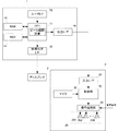
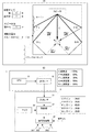
以下、本発明の実施形態に係る放音システムについて説明する。図1は、本実施形態の放音システムを実現するための構成を示すブロック図である。 Hereinafter, a sound emission system according to an embodiment of the present invention will be described. FIG. 1 is a block diagram showing a configuration for realizing the sound emission system of the present embodiment.
図1に示すように、放音システムは、パーソナルコンピュータ(以下、PCと言う。)等の情報処理装置とスピーカ装置(放音装置)により実現される。図1に示すPC1は、スピーカ装置のスピーカアレイが出力する音声ビームの経路を計算(シミュレーション)し、その結果をスピーカ装置に送信する。スピーカ装置は、計算結果に基づいて音声ビームの出力角度を設定する。
As shown in FIG. 1, the sound emission system is realized by an information processing device such as a personal computer (hereinafter referred to as a PC) and a speaker device (sound emission device). The
PC1は、CPU11、ユーザI/F12、RAM13、HDD14、映像出力I/F15、および出力I/F16を備えた一般的なPCである。CPU11には、ユーザI/F12、RAM13、HDD14、映像出力I/F15、および出力I/F16が接続されている。
The PC 1 is a general PC that includes a
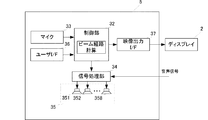
スピーカ装置3は、入力I/F31、制御部32、マイク33、信号処理部34、およびスピーカアレイ35(スピーカユニット351〜358)を備えている。制御部32には、入力I/F31、マイク33、および信号処理部34が接続され、信号処理部34にはスピーカアレイ35の各スピーカユニット351〜358が接続されている。
The
信号処理部34は、制御部32の制御に応じて、入力される音声信号に所定のディレイを付与し、スピーカアレイ35の各スピーカユニット351〜358に供給する。信号処理部34は、このディレイ量を変更することで、複数方向に音声ビームを出力することができる。
The
なお、出力I/F16および入力I/F31の規格はどの様なものであってもよいが、例えばUSB、HDMI(登録商標)を用いる。
Note that the output I /
PC1のCPU11は、スピーカ装置3が出力する音声ビーム経路のシミュレーションを行う機能を有する。すなわち、CPU11は、HDD14に記憶されているシミュレーション用のソフトウェアを読み出し、これをRAM13上に展開することで音声ビーム経路のシミュレーションを行う。例えば、ユーザが専用ソフトウェアをPC1のOSにインストールして(またはWEBブラウザ上で実行して)、シミュレーションを行う。
The
ユーザは、キーボードやマウス等からなるユーザI/F12を用いてPC1を操作し、シミュレーションに必要な各種数値を入力する。例えば、室内形状(部屋のサイズ)、スピーカ装置の壁からの距離、視聴位置(スピーカ装置との相対距離)を入力する。CPU11は、映像出力I/F15を介してディスプレイ2に上記各種数値を入力するための画面を表示する(図2(A)を参照)。
The user operates the PC 1 using the user I /
CPU11は、ユーザI/F12から入力された各種数値に基づいて、音声ビームの壁面反射の角度を計算し、スピーカ装置が出力する音声ビーム経路を計算する。CPU11は、計算した音声ビーム経路をディスプレイ2に表示し、計算結果(各音声ビームの出力角度)をスピーカ装置3に出力する(図3を参照)。なお、計算結果の表示は本発明のおいて必須ではない。
The
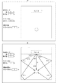
図2(A)は、ディスプレイ2に表示される画面(各種数値を入力するための画面)を示した図である。ユーザは、同図(A)の画面を見ながら、部屋の幅、奥行き、スピーカ装置の壁からの距離、視聴位置を入力する。これらの数値を入力すると、CPU11は、これらの値に基づいて、音声ビーム経路を計算し、同図(B)に示す画面を計算結果として表示する。
FIG. 2A is a diagram showing a screen (screen for inputting various numerical values) displayed on the
同図(B)に示すように、センタ(C)チャンネルは、スピーカ装置正面から視聴位置までの最短経路を音声ビーム経路として矢印で表示する。フロント右(FR)チャンネルおよびフロント左(FL)チャンネルは、室内の壁面に1回反射して視聴位置に到達する最短経路を音声ビーム経路として矢印で表示する。リア右(SR)チャンネルおよびリア左(SL)チャンネルは、室内の横壁面(紙面左右に示す壁面)と後壁面(紙面下側の壁面)で2回反射して視聴位置に到達する最短経路を音声ビーム経路として矢印で表示する。 As shown in FIG. 5B, the center (C) channel displays the shortest path from the front of the speaker device to the viewing position as an audio beam path with an arrow. In the front right (FR) channel and front left (FL) channel, the shortest path that reaches the viewing position after being reflected once on the wall surface in the room is displayed as an audio beam path by arrows. The rear right (SR) channel and rear left (SL) channel are the shortest paths that reach the viewing position after being reflected twice by the indoor horizontal wall surface (wall surface shown on the left and right of the paper surface) and the rear wall surface (wall surface below the paper surface). The sound beam path is indicated by an arrow.
また、図3に示すように、CPU11は、出力I/F16を介して、計算した各音声ビームの出力角度(θC、θFR、θFL、θSR、θSR)をスピーカ装置3に出力する。スピーカ装置3の制御部32は、入力I/F31を介して入力した各音声ビームの出力角度に基づいて、各音声ビームについて、信号処理部34に設定すべきディレイ量を計算させる。
Further, as shown in FIG. 3, the
制御部32は、この計算結果に基づいて、信号処理部34が設定する各スピーカユニットのディレイ量(dC1〜dC8、dFR1〜dFR8、dFL1〜dFL8、dSR1〜dSR8、dSL1〜dSL8)を制御する。
Based on the calculation result, the
このように、スピーカ装置3は、スピーカ装置の設置位置(壁からの距離および視聴位置との相対距離)と室内形状の入力に応じてPC1がシミュレーションした結果に基づき、各音声ビームの出力角度を設定するため、マイクを用いて出力角度の測定を行わずとも、高速に出力角度の設定を行うことができる。
As described above, the
なお、上述の計算結果の表示は、本発明において必須ではなく、ディスプレイ2も必須の構成要素ではない。例えば、スピーカ装置に表示部(OSD)を設け、ディスプレイ2に代えて、ユーザが各種数値を入力するための画面を表示してもよい。
In addition, the display of the above-mentioned calculation result is not essential in the present invention, and the
また、スピーカ装置が上記シミュレーション機能を内蔵した放音システムとすることも可能である。この場合、スピーカ装置が、放音装置としての機能とシミュレーション装置としての機能の両方を内蔵した態様となる。図4は、シミュレーション機能を内蔵する場合のスピーカ装置5の構成を示すブロック図である。なお、図1に示したスピーカ装置3と同じ構成については同一の符号を付し、その説明を省略する。なお、図4のスピーカアレイ5では、制御部32がスピーカ装置3のROM(不図示)からシミュレーション用のソフトウェアを読み出し、これをRAM(不図示)に展開し、実行する。
Moreover, it is also possible to use a sound emitting system in which the speaker device incorporates the simulation function. In this case, the speaker device has a mode in which both a function as a sound emitting device and a function as a simulation device are incorporated. FIG. 4 is a block diagram showing a configuration of the
同図におけるスピーカ装置5は、制御部32に接続されるユーザI/F36と映像出力I/F37と、をさらに備えている。ユーザI/F36は、上記PC1のユーザI/F12と同様の機能を有し、シミュレーションに必要な各種数値を入力するものである。映像出力I/F37は、上記PC1の映像出力I/F15と同様の機能を有し、制御部32は、この映像出力I/F37を介して、ディスプレイ2に各種数値を入力するための画面を表示したり、計算結果を表示したりする。
The
スピーカ装置5における制御部32は、図1のCPU11と同様に、ユーザI/F36から入力された各種数値に基づいて、音声ビームの壁面反射の角度を計算し、音声ビーム経路を計算し、ディスプレイ2に表示する。また、制御部32は、計算した各音声ビームの出力角度に基づいて、信号処理部34が設定する各スピーカユニットのディレイ量を制御する。
Similar to the
このように、スピーカ装置単体でも本発明の放音システムを実現することが可能である。 Thus, the sound emitting system of the present invention can be realized even with a single speaker device.
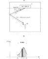
次に、図5は、マイク33を用いて出力角度を設定する場合の例を示す図である。なお、同図においては、説明を容易にするために、FLチャンネルの音声ビームのみ示している。スピーカ装置3は、聴取位置に設置されるマイク33を備えている。制御部32は、シミュレーションの結果に基づいて室内にテスト音声ビームを(スイープ)出力し、マイク33が収音した音声信号のレベルに応じて出力角度の設定を行う。
Next, FIG. 5 is a diagram illustrating an example of setting an output angle using the
この場合、マイクを用いて出力角度の測定を行うが、シミュレーションの結果に基づいてテスト音声ビームを出力するため、従来よりも出力角度の設定を高速化することができる。 In this case, the output angle is measured using a microphone, but since the test sound beam is output based on the result of the simulation, the setting of the output angle can be speeded up as compared with the conventional case.
すなわち、同図(A)に示すように、シミュレーションで求められた出力角度θ1の付近(例えば±3度程度:θ3〜θ4)だけテスト音声ビームをスイープさせる。測定分解能が1度である場合、θ1+1度、θ1+2度、θ1+3度、θ1−1度、θ2−2度、θ1−3度、の7つの角度についてテスト音声ビームを出力し、各テスト音声ビームの出力角度について、マイク33で収音した音声信号のレベルを分布化する。そして、制御部32は、テスト音声ビームのレベルがピークを示すときの角度(θ2)に出力角度を調整する。これにより、シミュレーションの結果よりも高精度に音声ビームの出力角度を設定することができる。また、シミュレーションの結果に応じて、特定の範囲にのみテスト音声ビームを出力するため、全範囲(0度〜180度)に測定を行う必要がなく、高速かつ高精度に出力角度を設定することができる。
That is, as shown in FIG. 5A, the test sound beam is swept only in the vicinity of the output angle θ1 obtained by the simulation (for example, about ± 3 degrees: θ3 to θ4). When the measurement resolution is 1 degree, the test sound beam is output for seven angles of θ1 + 1 degree, θ1 + 2 degree, θ1 + 3 degree, θ1-1 degree, θ2-2 degree, and θ1-3 degree. For the output angle, the level of the audio signal collected by the
なお、同図(A)および同図(B)では、全ての音声ビームについて、測定を行う例を示したが、一部のチャンネルのみ測定を行うようにすることも可能である。例えば、リアチャンネルのみ測定を行う、といった態様も可能である。リアチャンネルは、2回反射を行うため、シミュレーションと実測のずれが大きくなると音声ビームが聴取位置に到達しなくなる可能性もあり、精度を高めるためにリアチャンネルだけ測定を行う、ということも可能である。 Note that although FIGS. (A) and (B) show an example in which measurement is performed for all sound beams, it is also possible to measure only some of the channels. For example, a mode in which only the rear channel is measured is possible. Since the rear channel reflects twice, the sound beam may not reach the listening position if the difference between the simulation and the actual measurement becomes large, and it is also possible to measure only the rear channel to improve accuracy. is there.
次に、図6は、図5の例よりも測定分解能を高くして出力角度を設定する場合の例を示す図である。同図の例では、シミュレーションで求められた出力角度θ1の付近(例えば±3度程度:θ3〜θ4)だけテスト音声ビームを出力するが、測定分解能を2倍とし、0.5度刻みで測定を行う。このように、測定分解能を2倍としても、特定の範囲にのみテスト音声ビームを出力するため、従来よりも高速に、かつ従来よりも測定分解能を高くし、さらに精度を高めることができる。 Next, FIG. 6 is a diagram illustrating an example in which the output angle is set with a higher measurement resolution than in the example of FIG. In the example shown in the figure, the test sound beam is output only in the vicinity of the output angle θ1 obtained by the simulation (for example, about ± 3 degrees: θ3 to θ4). I do. As described above, even when the measurement resolution is doubled, the test sound beam is output only in a specific range, so that the measurement resolution can be made higher than before, the measurement resolution higher than before, and the accuracy can be further improved.
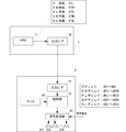
次に、図7(A)は、音声ビームの減衰度を表示する場合の音声ビーム経路の計算結果を示した図である。この例では、カーテン等の反射率が低いものや、室内にビームが反射しない箇所(開いた扉等)を入力する場合の音声ビーム経路を計算する。ユーザは、ユーザI/F12を用いて、カーテン等の位置を入力する。例えば、画面上に表示されているカーテンアイコン等をドラッグ&ドロップすることにより入力を行う。
Next, FIG. 7A is a diagram showing the calculation result of the sound beam path when displaying the attenuation of the sound beam. In this example, a sound beam path is calculated when a low reflectance such as a curtain or a portion (open door or the like) where the beam is not reflected in the room is input. The user inputs the position of the curtain or the like using the user I /
この例では、CPU11は、壁面の反射率を考慮する。例えば通常の壁面では反射率80%、カーテンが設置された壁面では反射率30%とする。CPU11は、これら反射率から各音声ビームの減衰度を計算し、計算結果をスピーカ装置3に出力する。
In this example, the
同図(A)および同図(B)に示すように、Cチャンネルの音声ビームは、直接到来するため、CPU11は、減衰度100%(減衰しない)の結果を出力する。FRチャンネルの音声ビームは、通常の壁面で1回反射して視聴位置に到達するため、CPU11は、減衰度80%の結果を出力する。また、FLチャンネルの音声ビームは、カーテンが設置された壁面で1回反射して視聴位置に到達するため、CPU11は、減衰度30%の結果を出力する。SLおよびSRチャンネルの音声ビームは、通常の壁面で2回反射して視聴位置に到達するため、CPU11は、減衰度64%の結果を出力する。また、減衰度に応じて音声ビームの線の太さを変更する。
As shown in FIGS. 6A and 6B, since the C channel sound beam directly arrives, the
制御部32は、上記の減衰度から、各チャンネルの音声ビームのゲインを設定する。FRチャンネルは、減衰度80%であるため、Cチャンネルの音声ビームよりもゲインを高くする(例えばCチャンネル34dBに対し、36dBとする)。SLおよびSRチャンネルは、減衰度64%であるため、さらにゲインを高くする(例えば38dBとする)。FLチャンネルは、減衰度30%であるため、最もゲインを高くする(例えば42dBとする)。
The
なお、同図(B)に示すゲインの値(dB)は、説明のための一例を示したものであり、実際の装置で設定されるゲインの値ではない。理想的には全ての音声ビームが均等なレベルで聴取位置に到達するようにゲインを調整すればよい。例えば、減衰度とゲインの関係を示したテーブルを予め用意しておき、このテーブルを読み出すことでゲインを設定する。 Note that the gain value (dB) shown in FIG. 5B is an example for explanation, and is not a gain value set by an actual apparatus. Ideally, the gain may be adjusted so that all the sound beams reach the listening position at an equal level. For example, a table showing the relationship between attenuation and gain is prepared in advance, and the gain is set by reading this table.
このように、本実施形態の放音システムは、シミュレーションの結果に応じて高速にゲインを調整することが可能である。 Thus, the sound emission system of this embodiment can adjust the gain at high speed according to the result of the simulation.
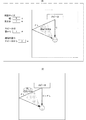
次に、図8は、室内に障害物が設置されている場合において、障害物を避けて聴取位置に到達するようにビーム経路を計算する場合の例を示す図である。なお、同図においては、説明を容易にするために、FLチャンネルの音声ビームのみ示している。 Next, FIG. 8 is a diagram illustrating an example in which a beam path is calculated so as to reach the listening position while avoiding an obstacle when an obstacle is installed in the room. In the figure, only the FL channel sound beam is shown for ease of explanation.
同図(A)に示すように、この例では、ユーザは、ユーザI/F12を用いて、室内の空間形状(幅、奥行き、高さ)を入力する。CPU11は、入力された空間形状から、室内の立体図を表示する。
As shown in FIG. 5A, in this example, the user inputs the indoor space shape (width, depth, height) using the user I /
また、この例では、ユーザは、ユーザI/F12を用いて、室内に設置された障害物の形状と位置を入力する。入力方法は、例えば、画面上に表示されている障害物アイコンを立体図内にドラッグ&ドロップすることにより行う。
In this example, the user uses the user I /
CPU11は、上述と同様に、各音声ビームの経路を計算するが、障害物が存在した場合、この障害物を避けて聴取位置に到達するようにビーム経路を計算する。例えば、壁面を反射して音声ビームを到達させることができないと計算された場合、天井面で音声ビームを反射して視聴位置に到達させることができるビーム経路を計算する。この場合、CPU11は、水平方向の出力角度および垂直方向の出力角度を計算する。CPU11は、この計算結果(水平方向の出力角度θHおよび垂直方向の出力角度θL)をスピーカ装置3に出力する。
The
スピーカ装置3の制御部32は、同図(B)に示すように、入力された水平方向の出力角度θHおよび垂直方向の出力角度θLを信号処理部34に設定し、音声ビームの出力角度を設定する。
As shown in FIG. 5B, the
このように、マイクを用いた測定が困難な場合であっても、シミュレーションの結果を用いて出力角度を設定することができる。従来のように、マイクを用いて測定を行うと、水平0度〜180度の測定を複数回行う必要があり、多大な時間がかかってしまうが、本実施形態によれば、平面上の反射でビーム経路が確保できない場合であっても、天井面等の反射を用いた立体的な経路を計算して、高速に出力角度を設定することが可能である。 Thus, even when measurement using a microphone is difficult, the output angle can be set using the result of simulation. If the measurement is performed using a microphone as in the prior art, it is necessary to perform the horizontal 0-degree to 180-degree measurement a plurality of times, which takes a lot of time. Even if the beam path cannot be secured, it is possible to calculate a three-dimensional path using reflection on the ceiling surface and set the output angle at high speed.
なお、この例では、スピーカアレイは床面に設置されているものとみなして音声ビーム経路を計算しているが、スピーカアレイの床面からの設置高さをさらに入力し、ビーム経路の計算を行ってもよい。 In this example, the sound beam path is calculated assuming that the speaker array is installed on the floor. However, the installation height from the floor of the speaker array is further input to calculate the beam path. You may go.
次に、図9は、室内にビームが反射しない箇所(開いた扉等)を入力する場合の音声ビーム経路を計算する例を示す図である。同図(A)に示すように、この場合においても、ユーザは、ユーザI/F12を用いて、ビームが反射しない箇所を入力する。例えば、画面上に表示されている扉アイコン等をドラッグ&ドロップすることにより入力を行う。
Next, FIG. 9 is a diagram illustrating an example of calculating an audio beam path when a portion (open door or the like) where the beam does not reflect is input into the room. As shown in FIG. 5A, also in this case, the user uses the user I /
この場合、SRチャンネルは、室内後方に設置された開放扉により、視聴位置まで反射経路を確保することができないため、CPU11は、ディスプレイ2に「反射できません」等と表示するとともに、スピーカ装置3にSRチャンネルを設定することができない旨を示す情報を出力する。
In this case, since the SR channel cannot secure a reflection path to the viewing position by the open door installed in the rear of the room, the
スピーカ装置3の制御部32は、上記情報を入力すると、SRチャンネルの音声ビームを出力しないように設定する。このとき、制御部32は、同図(B)に示すように、リアチャンネルの音声をフロントチャンネルの音声ビームにミキシングして再生する(5.1チャンネル→3.1チャンネル)。なお、同図(B)に示すような画面(FL+SLチャンネル、FR+SRチャンネル)をディスプレイ2に表示してもよい。
When the information is input, the
このように、本実施形態によれば、マイクを用いた測定を行わなくとも反射経路を確保できない音声ビームを推定することができるため、このような音声ビームの切替も高速化することができる。 As described above, according to the present embodiment, it is possible to estimate an audio beam that cannot secure a reflection path without performing measurement using a microphone, and thus switching of the audio beam can be speeded up.
次に、図10は、許容到達角度を考慮する場合の音声ビーム経路の計算結果を示した図である。許容到達角度は、例えばITU(International Telecommunication Union)で勧告されているスピーカ配置に基づくものであり、サラウンド感が得られる範囲の目安となるものである。本実施形態では、扇形状のハッチングにより許容到達角度を示している。許容到達角度は、予め規定されたものであってもよいし、ユーザがユーザI/F16を用いて入力してもよい。なお、同図においては説明を容易にするために、CチャンネルおよびFLチャンネルの音声ビームのみ示している。
Next, FIG. 10 is a diagram showing a calculation result of the sound beam path when the allowable arrival angle is considered. The allowable reach angle is based on, for example, a speaker arrangement recommended by ITU (International Telecommunication Union), and serves as a standard of a range where a surround feeling can be obtained. In the present embodiment, the allowable reach angle is indicated by fan-shaped hatching. The allowable reach angle may be specified in advance, or may be input by the user using the user I /
この場合、室内の幅が大きく、スピーカアレイと聴取位置との相対距離が小さいため、FLチャンネルの音声ビームが許容到達角度内で聴取位置に到達しない。よって、CPU11は、スピーカ装置3に、FLチャンネルの音声ビームが許容到達角度内で到達しない旨を示す情報を出力する。
In this case, since the width of the room is large and the relative distance between the speaker array and the listening position is small, the sound beam of the FL channel does not reach the listening position within the allowable reaching angle. Therefore, the
スピーカ装置3の制御部32は、上記情報を入力すると、同図(B)に示すように、FLチャンネルの音声をCチャンネルの音声にミキシングし、Cチャンネルの音声ビームにおいてFLチャンネルの音声が含まれるように設定する。このように、複数の音声ビームにおいて同じチャンネルの音声を出力し、異なる方向から同じ音声を到達させると、その中間方向に仮想的な音源(虚像音源:ファントム)を形成することができる。このファントムにより、許容到達角度内で音声が到達するように定位させることが可能である。なお、同図(B)に示すような画面(ファントムの到達経路)をディスプレイ2に表示してもよい。
When the above information is input, the
また、CPU11は、FLチャンネルの音声ビームの出力角度と許容到達角度とのずれ量を出力してもよい。この場合、制御部32がずれ量に応じて、Cチャンネルの音声ビームに含まれるFLチャンネルの音声のレベル(重みづけ)を変更する。例えば、Cチャンネルの音声ビームにおいて、FLチャンネルの音声の重みづけを大きくすれば、ファントムをセンタ寄りに移動させることができる。よって、許容到達角度のずれ量がセンタ側に大きければCチャンネルの音声ビームにおいてFLチャンネルの音声の重みづけを大きくすればよい。
Further, the
なお、許容到達角度内で音声ビームが到達しない場合においても、その音声ビームのチャンネルを他のチャンネルにミキシングし、再生するようにしてもよい(例えば5.1チャンネル→3.1チャンネルとしてもよい)。 Note that even when the sound beam does not reach within the allowable reach angle, the channel of the sound beam may be mixed with another channel and reproduced (for example, from 5.1 channel to 3.1 channel). ).
1−PC
2−ディスプレイ
3−スピーカ装置
1-PC
2-Display 3-Speaker device
Claims (6)
前記シミュレーション装置は、スピーカアレイの設置位置、および室内形状を入力する入力手段と、
前記入力手段から入力されたスピーカアレイの設置位置、および室内形状から、前記音声ビームの壁面反射の角度を計算し、前記スピーカアレイが出力する音声ビームの経路を計算する計算手段と、
前記計算手段の計算結果を出力する出力部と、を備え、
前記放音装置は、前記計算結果を入力する入力部と、
前記計算結果に基づいて、音声ビームの出力角度を制御する制御部と、
を備えた放音システム。 A sound emitting system comprising a sound emitting device including a speaker array that outputs a sound beam, and a simulation device that simulates a path of the sound beam,
The simulation apparatus includes an input unit for inputting a speaker array installation position and a room shape;
Calculating means for calculating the angle of reflection of the wall surface of the sound beam from the installation position of the speaker array input from the input means and the room shape, and calculating the path of the sound beam output from the speaker array;
An output unit for outputting a calculation result of the calculation means,
The sound emitting device includes an input unit for inputting the calculation result;
A control unit for controlling the output angle of the sound beam based on the calculation result;
Sound emission system with
前記制御部は、前記計算結果に基づいて、室内にテスト音声ビームを出力し、
前記音声ビームの出力角度を、前記マイクが収音したテスト音声ビームのレベルがピークを示すときの角度に調整する請求項1に記載の放音システム。 The sound emitting device includes a microphone installed at a listening position,
The control unit outputs a test sound beam into the room based on the calculation result,
The sound emission system according to claim 1, wherein the output angle of the sound beam is adjusted to an angle when the level of the test sound beam picked up by the microphone shows a peak.
前記計算手段は、前記壁面の反射率から音声ビームの減衰度を計算し、
前記出力部は、前記計算結果として、音声ビームの減衰度をさらに出力し、
前記制御部は、前記減衰度に応じて前記音声ビームの出力レベルを制御する請求項1、または請求項2に記載の放音システム。 The input means further inputs the reflectance of the wall surface,
The calculation means calculates the attenuation of the sound beam from the reflectance of the wall surface,
The output unit further outputs a sound beam attenuation as the calculation result,
The sound emission system according to claim 1, wherein the control unit controls an output level of the sound beam according to the degree of attenuation.
前記計算手段は、前記音声ビームが前記障害物を避けて聴取位置に到達するようにビーム経路を計算する請求項1、請求項2、または請求項3のいずれかに記載の放音システム。 The input means of the simulation apparatus inputs the shape and position information of the obstacle in the room,
4. The sound emission system according to claim 1, wherein the calculation unit calculates a beam path so that the sound beam reaches a listening position while avoiding the obstacle.
前記シミュレーション装置は、聴取位置における各チャンネルの音声ビームの許容到達角度を設定する設定手段を備え、
前記放音装置の制御部は、前記計算手段が許容到達角度内で聴取位置に到達する音声ビームの経路を計算できないチャンネルが存在した場合に、他のチャンネルの音声ビームで代替出力を行うように設定する請求項1乃至請求項4のいずれかに記載の放音システム。 The sound beam is a plurality of sound beams of multi-channel surround sound,
The simulation apparatus includes setting means for setting an allowable reaching angle of the sound beam of each channel at the listening position,
The control unit of the sound emitting device performs an alternative output with the sound beam of another channel when there is a channel in which the calculation unit cannot calculate the path of the sound beam that reaches the listening position within the allowable arrival angle. The sound emission system according to any one of claims 1 to 4, wherein the sound emission system is set.
複数の音声ビームにそのチャンネルの音声を入力し、所定位置に虚像音源を定位させる請求項5に記載の放音システム。 The control unit of the sound emitting device, when there is a channel that the calculation means can not calculate the path of the sound beam that reaches the listening position within the allowable arrival angle,
6. The sound emission system according to claim 5, wherein sound of the channel is input to a plurality of sound beams, and the virtual image sound source is localized at a predetermined position.
Priority Applications (1)
| Application Number | Priority Date | Filing Date | Title |
|---|---|---|---|
| JP2008159983A JP5211882B2 (en) | 2008-06-19 | 2008-06-19 | Sound emission system |
Applications Claiming Priority (1)
| Application Number | Priority Date | Filing Date | Title |
|---|---|---|---|
| JP2008159983A JP5211882B2 (en) | 2008-06-19 | 2008-06-19 | Sound emission system |
Publications (2)
| Publication Number | Publication Date |
|---|---|
| JP2010004204A true JP2010004204A (en) | 2010-01-07 |
| JP5211882B2 JP5211882B2 (en) | 2013-06-12 |
Family
ID=41585558
Family Applications (1)
| Application Number | Title | Priority Date | Filing Date |
|---|---|---|---|
| JP2008159983A Active JP5211882B2 (en) | 2008-06-19 | 2008-06-19 | Sound emission system |
Country Status (1)
| Country | Link |
|---|---|
| JP (1) | JP5211882B2 (en) |
Cited By (7)
| Publication number | Priority date | Publication date | Assignee | Title |
|---|---|---|---|---|
| JP2010011461A (en) * | 2008-06-27 | 2010-01-14 | Mitsubishi Digital Electronics America Inc | System and method for television with integrated sound projection system |
| JP2010063101A (en) * | 2008-09-02 | 2010-03-18 | Mitsubishi Digital Electronics America Inc | System and method for television with integrated sound projection system |
| JP2014033266A (en) * | 2012-08-01 | 2014-02-20 | Yamaha Corp | Sound emission device |
| JP2015126358A (en) * | 2013-12-26 | 2015-07-06 | ヤマハ株式会社 | Speaker device |
| JP2016116193A (en) * | 2014-12-18 | 2016-06-23 | ヤマハ株式会社 | Speaker array apparatus |
| US10038963B2 (en) | 2013-08-19 | 2018-07-31 | Yamaha Corporation | Speaker device and audio signal processing method |
| JP2019033472A (en) * | 2017-08-04 | 2019-02-28 | ハーマン インターナショナル インダストリーズ インコーポレイテッド | Adjusting perceived elevation of audio image on solid cinema screen |
Citations (3)
| Publication number | Priority date | Publication date | Assignee | Title |
|---|---|---|---|---|
| JP2006013711A (en) * | 2004-06-23 | 2006-01-12 | Yamaha Corp | Speaker array unit and its voice beam setting method |
| JP2006025153A (en) * | 2004-07-07 | 2006-01-26 | Yamaha Corp | Directivity control method of speaker system and audio reproducing device |
| JP2006060610A (en) * | 2004-08-20 | 2006-03-02 | Yamaha Corp | Sound-reproducing device and sound beam reflection position correcting method for the sound reproducing device |
-
2008
- 2008-06-19 JP JP2008159983A patent/JP5211882B2/en active Active
Patent Citations (3)
| Publication number | Priority date | Publication date | Assignee | Title |
|---|---|---|---|---|
| JP2006013711A (en) * | 2004-06-23 | 2006-01-12 | Yamaha Corp | Speaker array unit and its voice beam setting method |
| JP2006025153A (en) * | 2004-07-07 | 2006-01-26 | Yamaha Corp | Directivity control method of speaker system and audio reproducing device |
| JP2006060610A (en) * | 2004-08-20 | 2006-03-02 | Yamaha Corp | Sound-reproducing device and sound beam reflection position correcting method for the sound reproducing device |
Cited By (8)
| Publication number | Priority date | Publication date | Assignee | Title |
|---|---|---|---|---|
| JP2010011461A (en) * | 2008-06-27 | 2010-01-14 | Mitsubishi Digital Electronics America Inc | System and method for television with integrated sound projection system |
| JP2010063101A (en) * | 2008-09-02 | 2010-03-18 | Mitsubishi Digital Electronics America Inc | System and method for television with integrated sound projection system |
| JP2014033266A (en) * | 2012-08-01 | 2014-02-20 | Yamaha Corp | Sound emission device |
| US10038963B2 (en) | 2013-08-19 | 2018-07-31 | Yamaha Corporation | Speaker device and audio signal processing method |
| JP2015126358A (en) * | 2013-12-26 | 2015-07-06 | ヤマハ株式会社 | Speaker device |
| JP2016116193A (en) * | 2014-12-18 | 2016-06-23 | ヤマハ株式会社 | Speaker array apparatus |
| JP2019033472A (en) * | 2017-08-04 | 2019-02-28 | ハーマン インターナショナル インダストリーズ インコーポレイテッド | Adjusting perceived elevation of audio image on solid cinema screen |
| JP7299675B2 (en) | 2017-08-04 | 2023-06-28 | ハーマン インターナショナル インダストリーズ インコーポレイテッド | Adjusting the perceived height of the sound image on a solid movie screen |
Also Published As
| Publication number | Publication date |
|---|---|
| JP5211882B2 (en) | 2013-06-12 |
Similar Documents
| Publication | Publication Date | Title |
|---|---|---|
| JP5211882B2 (en) | Sound emission system | |
| US8249264B2 (en) | Method and system for automatically generating world environment reverberation from a game geometry | |
| Pätynen et al. | Analysis of concert hall acoustics via visualizations of time-frequency and spatiotemporal responses | |
| US9377941B2 (en) | Audio speaker selection for optimization of sound origin | |
| JP5611119B2 (en) | Acoustic simulator, acoustic consulting apparatus, and processing method thereof | |
| Soeta et al. | Effects of sound source location and direction on acoustic parameters in Japanese churches | |
| CN108379842B (en) | Game audio processing method and device, electronic equipment and storage medium | |
| Thomas et al. | Reverberation-based urban street sound level prediction | |
| JP2020031303A (en) | Voice generating program and voice generating apparatus in virtual space | |
| JP5486557B2 (en) | Reverberation processing device | |
| JP4363528B2 (en) | Sound field simulation system | |
| US10701508B2 (en) | Information processing apparatus, information processing method, and program | |
| KR101975920B1 (en) | Apparatus and method for synthesizing virtual sound | |
| Tenenbaum et al. | Hybrid method for numerical simulation of room acoustics: part 2-validation of the computational code RAIOS 3 | |
| US8644520B2 (en) | Morphing of aural impulse response signatures to obtain intermediate aural impulse response signals | |
| EP2552130A1 (en) | Method for sound signal processing, and computer program for implementing the method | |
| JP5092922B2 (en) | Beam path display device | |
| JP6326743B2 (en) | Information processing apparatus, AV receiver, and program | |
| JP2007003989A (en) | Sound environment analysis simulation system | |
| JP2006270425A (en) | Method and program for outputting sound, and information processor | |
| JP6200688B2 (en) | Sound field simulation device | |
| Keränen et al. | Prediction accuracies of ray-tracing and regression models in open-plan offices | |
| JP2010181824A (en) | Sound simulation apparatus and sound simulation program | |
| Piquet et al. | TWO DATASETS OF ROOM IMPULSE RESPONSES FOR NAVIGATION IN SIX DEGREES-OF-FREEDOM: A SYMPHONIC CONCERT HALL AND A FORMER PLANETARIUM | |
| JP2009100360A (en) | Sound image localization parameter calculating device, sound image localization control device, sound image localization device, and program |
Legal Events
| Date | Code | Title | Description |
|---|---|---|---|
| A621 | Written request for application examination |
Free format text: JAPANESE INTERMEDIATE CODE: A621 Effective date: 20110420 |
|
| A977 | Report on retrieval |
Free format text: JAPANESE INTERMEDIATE CODE: A971007 Effective date: 20120808 |
|
| A131 | Notification of reasons for refusal |
Free format text: JAPANESE INTERMEDIATE CODE: A131 Effective date: 20120821 |
|
| A521 | Written amendment |
Free format text: JAPANESE INTERMEDIATE CODE: A523 Effective date: 20121016 |
|
| RD02 | Notification of acceptance of power of attorney |
Free format text: JAPANESE INTERMEDIATE CODE: A7422 Effective date: 20121016 |
|
| TRDD | Decision of grant or rejection written | ||
| A01 | Written decision to grant a patent or to grant a registration (utility model) |
Free format text: JAPANESE INTERMEDIATE CODE: A01 Effective date: 20130129 |
|
| A61 | First payment of annual fees (during grant procedure) |
Free format text: JAPANESE INTERMEDIATE CODE: A61 Effective date: 20130211 |
|
| R150 | Certificate of patent or registration of utility model |
Ref document number: 5211882 Country of ref document: JP Free format text: JAPANESE INTERMEDIATE CODE: R150 Free format text: JAPANESE INTERMEDIATE CODE: R150 |
|
| FPAY | Renewal fee payment (event date is renewal date of database) |
Free format text: PAYMENT UNTIL: 20160308 Year of fee payment: 3 |