JP2010004202A - Portable terminal device with waterproof structure - Google Patents
Portable terminal device with waterproof structure Download PDFInfo
- Publication number
- JP2010004202A JP2010004202A JP2008159973A JP2008159973A JP2010004202A JP 2010004202 A JP2010004202 A JP 2010004202A JP 2008159973 A JP2008159973 A JP 2008159973A JP 2008159973 A JP2008159973 A JP 2008159973A JP 2010004202 A JP2010004202 A JP 2010004202A
- Authority
- JP
- Japan
- Prior art keywords
- waterproof
- packing
- cable
- portable terminal
- housing
- Prior art date
- Legal status (The legal status is an assumption and is not a legal conclusion. Google has not performed a legal analysis and makes no representation as to the accuracy of the status listed.)
- Granted
Links
Images

Classifications
-
- H—ELECTRICITY
- H04—ELECTRIC COMMUNICATION TECHNIQUE
- H04M—TELEPHONIC COMMUNICATION
- H04M1/00—Substation equipment, e.g. for use by subscribers
- H04M1/02—Constructional features of telephone sets
- H04M1/18—Telephone sets specially adapted for use in ships, mines, or other places exposed to adverse environment
-
- G—PHYSICS
- G06—COMPUTING; CALCULATING OR COUNTING
- G06F—ELECTRIC DIGITAL DATA PROCESSING
- G06F1/00—Details not covered by groups G06F3/00 - G06F13/00 and G06F21/00
- G06F1/16—Constructional details or arrangements
- G06F1/1613—Constructional details or arrangements for portable computers
- G06F1/1615—Constructional details or arrangements for portable computers with several enclosures having relative motions, each enclosure supporting at least one I/O or computing function
- G06F1/1616—Constructional details or arrangements for portable computers with several enclosures having relative motions, each enclosure supporting at least one I/O or computing function with folding flat displays, e.g. laptop computers or notebooks having a clamshell configuration, with body parts pivoting to an open position around an axis parallel to the plane they define in closed position
-
- G—PHYSICS
- G06—COMPUTING; CALCULATING OR COUNTING
- G06F—ELECTRIC DIGITAL DATA PROCESSING
- G06F1/00—Details not covered by groups G06F3/00 - G06F13/00 and G06F21/00
- G06F1/16—Constructional details or arrangements
- G06F1/1613—Constructional details or arrangements for portable computers
- G06F1/1633—Constructional details or arrangements of portable computers not specific to the type of enclosures covered by groups G06F1/1615 - G06F1/1626
- G06F1/1656—Details related to functional adaptations of the enclosure, e.g. to provide protection against EMI, shock, water, or to host detachable peripherals like a mouse or removable expansions units like PCMCIA cards, or to provide access to internal components for maintenance or to removable storage supports like CDs or DVDs, or to mechanically mount accessories
-
- G—PHYSICS
- G06—COMPUTING; CALCULATING OR COUNTING
- G06F—ELECTRIC DIGITAL DATA PROCESSING
- G06F1/00—Details not covered by groups G06F3/00 - G06F13/00 and G06F21/00
- G06F1/16—Constructional details or arrangements
- G06F1/1613—Constructional details or arrangements for portable computers
- G06F1/1633—Constructional details or arrangements of portable computers not specific to the type of enclosures covered by groups G06F1/1615 - G06F1/1626
- G06F1/1675—Miscellaneous details related to the relative movement between the different enclosures or enclosure parts
- G06F1/1681—Details related solely to hinges
-
- H—ELECTRICITY
- H04—ELECTRIC COMMUNICATION TECHNIQUE
- H04M—TELEPHONIC COMMUNICATION
- H04M1/00—Substation equipment, e.g. for use by subscribers
- H04M1/02—Constructional features of telephone sets
- H04M1/0202—Portable telephone sets, e.g. cordless phones, mobile phones or bar type handsets
- H04M1/0206—Portable telephones comprising a plurality of mechanically joined movable body parts, e.g. hinged housings
- H04M1/0208—Portable telephones comprising a plurality of mechanically joined movable body parts, e.g. hinged housings characterized by the relative motions of the body parts
- H04M1/0214—Foldable telephones, i.e. with body parts pivoting to an open position around an axis parallel to the plane they define in closed position
- H04M1/0216—Foldable in one direction, i.e. using a one degree of freedom hinge
Abstract
Description
本発明は防水構造付き携帯端末装置に関し、特に折り畳み式携帯電話機など複数の筐体に収納された電子回路間を接続するケーブルを用いた防水構造付き携帯端末装置に関する。 The present invention relates to a portable terminal device with a waterproof structure, and more particularly to a portable terminal device with a waterproof structure using a cable for connecting electronic circuits housed in a plurality of casings such as a folding cellular phone.
いつでもどこでも、場所と環境を選ばずに使用される携帯端末装置である携帯電話機は、防水対策を施したものも実用化されている。例えば、防水性のチューブを用いて複数の筐体に収納された電子回路間を接続するケーブルの防水対策を施したものが知られている(例えば特許文献1、特許文献2参照)。
しかし、携帯端末装置では、少ない部品で省スペースによる小型化、軽量化が求められる。そのため携帯端末装置に防水機能を付加するには、小さい部品、少ない部品で確実な防水構造を実現することが求められている。 However, the mobile terminal device is required to be small and light by space saving with few parts. Therefore, in order to add a waterproof function to a portable terminal device, it is required to realize a reliable waterproof structure with small parts and few parts.
本発明は、開口部を有する筐体と、開口部を通して前記筐体内の電子回路と他の電子回路とを電気的に接続するケーブルと、ケーブルが挿通される挿通孔が貫通形成されて前記開口部に挿入される防水パッキンとを備え、防水パッキンは、筒状形状であって、外側に第1防水圧入リブと、内側に第2防水圧入リブと、を有し、第1防水圧入リブと前記第2防水圧入リブとは挿通孔の軸方向に互いにずれた位置に設けた防水構造を用いて、防水構造付き携帯端末装置を構成している。この構成により、第1防水圧入リブの変形と前記第2防水圧入リブの変形との間の互いの影響を小さくできるので、小さい部品、少ない部品で確実な防水機能を実現した携帯端末装置を提供することができる。 The present invention provides a housing having an opening, a cable that electrically connects an electronic circuit in the housing and another electronic circuit through the opening, and an insertion hole through which the cable is inserted to form the opening. A waterproof packing, which has a cylindrical shape, and has a first waterproof press-fit rib on the outside and a second waterproof press-fit rib on the inside, and the first waterproof press-fit rib The second waterproof press-fitting rib constitutes a portable terminal device with a waterproof structure using a waterproof structure provided at a position shifted from each other in the axial direction of the insertion hole. With this configuration, since the mutual influence between the deformation of the first waterproof press-fitting rib and the deformation of the second waterproof press-fit rib can be reduced, a portable terminal device that realizes a reliable waterproof function with a small number of parts and a small number of parts can do.
また、本発明は、防水パッキンの第1防水圧入リブは、挿通孔の軸方向の断面が半円形形状であり、防水パッキンの第2防水圧入リブは、挿通孔の軸方向の断面が長方形形状又は台形形状(ただし、角は丸くなっている)であるものを含む。この構成により、組み立て時等に防水パッキンを開口部に挿入する場合には第1防水圧入リブの挿通孔の軸方向の断面が半円形形状なので挿入が容易である一方、筐体を開閉する場合等ケーブルに力が加わった場合でも第2防水圧入リブの挿通孔の軸方向の断面が長方形形状又は台形形状(ただし、角は丸くなっている)なので、接触面積が大きく、確実に防水性を保つことを可能とする。 Further, according to the present invention, the first waterproof press-fit rib of the waterproof packing has a semicircular shape in the axial direction of the insertion hole, and the second waterproof press-fit rib of the waterproof packing has a rectangular shape in the axial direction of the insert hole. Or the thing which is trapezoid shape (however, the corners are rounded) is included. With this configuration, when the waterproof packing is inserted into the opening during assembly or the like, the axial section of the insertion hole of the first waterproof press-fitting rib is semicircular, so that the insertion is easy, while the housing is opened and closed. Even when force is applied to the cable, the axial cross section of the insertion hole of the second waterproof press-fitting rib is rectangular or trapezoidal (however, the corners are rounded), so the contact area is large and waterproofing is ensured. Makes it possible to keep.
また、本発明は、防水パッキンは、筒状形状の端部に係止部を有するものを含む。この構成により、係止部が防水パッキンを筐体に押し込むときのストッパーとして機能するため、防水パッキンを防水に適した最適位置に位置させることができる。 In the present invention, the waterproof packing includes one having a locking portion at the end of the cylindrical shape. With this configuration, since the locking portion functions as a stopper when the waterproof packing is pushed into the housing, the waterproof packing can be positioned at an optimal position suitable for waterproofing.
また本発明は、防水パッキンは、第1防水圧入リブを第2防水圧入リブよりも係止部と反対側の筒状形状の端部に近い位置に設けたものを含む。この構成により、第1防水圧入リブが内側、すなわち防水パッキンの係止部が外側になるように、防水パッキンを筐体の開口部に挿入しておけば、筐体を開閉する場合等ケーブルに力が加わった場合に防水パッキンが筐体の開口部から少し抜けかかった状態になったとしても、第1防水圧入リブが内側にあるので、防水性を保つことができ、防水性を高めることができる。 In the present invention, the waterproof packing includes a first waterproof press-fitting rib provided at a position closer to the end of the cylindrical shape on the opposite side of the locking portion than the second waterproof press-fitting rib. With this configuration, if the waterproof packing is inserted into the opening of the housing so that the first waterproof press-fitting rib is on the inside, that is, the locking portion of the waterproof packing is on the outside, the cable can be used to open and close the housing. Even if the waterproof packing is slightly removed from the opening of the housing when force is applied, the waterproofness can be maintained and the waterproofness can be improved because the first waterproof press-fitting rib is inside. Can do.
また本発明は、防水パッキンの筒状形状を長円形筒状形状とするものを含む。この構成により、長円形筒状形状の短手方向の厚さにより筐体の薄型化を達成しつつ、防水パッキンを筐体に押し込むときの防水パッキンに挿通したケーブルの両側を挿通孔の軸方向に押圧する押圧スペースが確保できる。そのため、押圧スペースを押すことにより、防水パッキンを筐体の挿通孔に押し込むことができる。 Moreover, this invention includes what forms the cylindrical shape of waterproof packing into an oval cylindrical shape. With this configuration, the thickness of the oval cylindrical shape in the short direction reduces the thickness of the housing, while the both sides of the cable inserted through the waterproof packing are pushed in the axial direction of the insertion hole when the waterproof packing is pushed into the housing. A pressing space for pressing can be secured. Therefore, the waterproof packing can be pushed into the insertion hole of the housing by pushing the pressing space.
また、本発明は、防水パッキンに隣接する位置にケーブル案内溝を有する抜け止め部材を着脱自在に備えるものを含む。そのため、ケーブルに外力が加わっても抜け止め部材がケーブルを所定形状に保ち、ケーブルと防水パッキンの挿通孔の密着を保つ防水機能を実現している。 Moreover, this invention includes what equips the position adjacent to a waterproof packing with the retaining member which has a cable guide groove so that attachment or detachment is possible. Therefore, even if an external force is applied to the cable, the retaining member keeps the cable in a predetermined shape and realizes a waterproof function that keeps the cable and the insertion hole of the waterproof packing in close contact.
本発明によれば、小さい部品、少ない部品で確実な防水機能を実現した携帯端末装置を提供することができる。 ADVANTAGE OF THE INVENTION According to this invention, the portable terminal device which implement | achieved the reliable waterproof function with a small component and few components can be provided.
(実施の形態1)
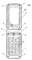
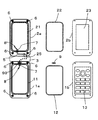
図1は、本発明の実施の形態1にかかる防水構造付き折り畳み式携帯端末装置の筐体を開いたときの平面図を示す。本発明の実施の形態1にかかる防水構造付き携帯端末装置100は、電話番号等を入力するテンキーなどの操作部を有する第一の筐体1と、液晶表示部を有する第二の筐体2と、両者の筐体を開閉自在に支持する連結部3から構成されている。図2は、本発明の実施の形態1にかかる防水構造付き携帯端末装置100の第一の筐体1から操作パネル13を、第二の筐体2から表示パネル23を、それぞれ外したときの平面図を示している。
(Embodiment 1)
FIG. 1: shows the top view when the housing | casing of the foldable portable terminal device with a waterproof
第一の筐体1は、2つの部分(ロアーケース1a及びロアーカバー1b)からなり、それぞれの部分の間に防水のためのパッキン12を挟んで複数のネジ4で固定することにより、筐体内に水が浸入することを防いでいる。第二の筐体2も同様に、2つの部分(アッパーケース2a及びアッパーカバー2b)からなり、それぞれの部分の間に防水のためのパッキン22を挟んで複数のネジ4で固定することにより、筐体内に水が浸入することを防いでいる。第一の筐体1と第二の筐体2は、防水性を保つために、例えば比較的硬い樹脂であるPA樹脂などの樹脂製であることが好ましい。
The
また、第一の筐体1(ロアーカバー1b)には操作パネル13が設けられている。また、第二の筐体2(アッパーカバー2b)には表示パネル23が設けられている。図1では図示していないが、第一の筐体1には、操作制御等を行うための電子回路が実装されたプリント基板が収納されている。また、第二の筐体2には、表示用電子回路が実装されたプリント基板が収納されている。そして、それぞれのプリント基板は、ケーブル5で接続されている。
An
図2に示したように、第一の筐体1(ロアーケース1a)にはパッキン保持用溝11が設けてあり、第二の筐体2(アッパーケース2a)にはパッキン保持用溝21が設けてある。第一の筐体用パッキン12と第二筐体用パッキン22は、それぞれパッキン保持用溝11とパッキン保持用溝21に嵌めて用いられる。
As shown in FIG. 2, a
なお、第一の筐体用パッキン12と第二筐体用パッキン22は、それぞれパッキン保持用溝11とパッキン保持用溝21に嵌めた状態で、パッキン保持用溝11とパッキン保持用溝21から盛り上がる大きさにしている。そのため、ロアーケース1a及びロアーカバー1bとアッパーケース2a及びアッパーカバー2bをそれぞれネジ止めすることにより、第一の筐体1のパッキン保持用溝11で囲まれた範囲と第二の筐体2のパッキン保持用溝21で囲まれた範囲が密閉空間となって防水される。
The first casing packing 12 and the
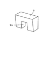
図2において、ケーブル用防水パッキンの抜け止め部材9は、後に図示するようにコの字形をしていて、第一の筐体1(ロアーケース1a)の抜け止め部材用固定溝99に嵌めこまれることにより、第一の筐体1に固定される。6はネジ穴であり、図1で示したようにネジ4がネジ止めされる。
In FIG. 2, the
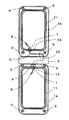
図3は、図2の第一の筐体1(ロアーケース1a)、第二の筐体2(アッパーケース2a)と連結部3を拡大した平面図である。図3において、第一の筐体1のパッキン保持用溝11の側壁には、ケーブル用パッキン7を固定する開口部であるパッキン用穴14が設けられていて、そのパッキン用穴14にはケーブル用パッキン7が嵌められていることを示している。同様に、第二の筐体2のパッキン保持用溝21の側壁には、ケーブル用パッキン7を固定する開口部であるパッキン用穴24が設けられていて、そのパッキン用穴24にはケーブル用パッキン7が嵌められている。
FIG. 3 is an enlarged plan view of the first casing 1 (
図4は、第一の筐体1のプリント基板と第二の筐体2のプリント基板を接続するケーブル5を一対のケーブル用パッキン7とともに示した図である。図4に示すように、ケーブル5の両端には、プリント基板に接続する接続端子8を予め固着している。また、ケーブル5は一対のケーブル用パッキン7の抜け止め部7aを筐体の外側にした状態(接続端子8から離れた側にした状態)で、それぞれの挿通孔7bに通している。ケーブル5は、図4のような姿に組み立ててから、図3のように、第一の筐体1と第二の筐体2に組み込まれる。
FIG. 4 is a view showing the
なお、図3の第一の筐体1のケーブル用防水パッキンの抜け止め部材9は、ケーブル5を組み込む前に一度、第一の筐体1(ロアーケース1a)から取り外しておき、ケーブル5を組み込み、ケーブル用パッキン7を第一の筐体1のパッキン用穴14に嵌めこんだ後に、ケーブル5の上から跨いで押さえるように第一の筐体1(ロアーケース1a)の抜け止め部材用固定溝99に固定する。
3 is removed from the first housing 1 (
抜け止め部材9は、ケーブル用パッキン7が第一の筐体1のパッキン用穴14から抜けないようにする作用と、ケーブル用パッキン7に対してケーブル5が所定の相対角度を保たせる(すなわち、まっすぐな状態を保たせる)作用を果たしている。もし、ケーブル5がケーブル用パッキン7に対して傾いて取り付くと、ケーブル5とケーブル用パッキン7の間に隙間が出来て水が浸入しやすくなるのであるが、抜け止め部材9がケーブル5のケーブル用パッキン7に対する角度を保つことによって防水機能を高めている。
The retaining
図3の第二の筐体2のケーブル用フック25は、ケーブル用パッキン7を第二の筐体2の開口部であるパッキン用穴24に嵌めこんだ後に、ケーブル5を引っ掛けて固定するためのフックである。ケーブル用フック25は、第二の筐体2に一体成形して、あるいは接着して設けている。第二の筐体2のパッキン用穴24から接続部3に至るケーブル5の長さは、第一の筐体1のパッキン用穴14から接続部3に至るケーブル5の長さより長い。そのため、パッキン用穴24から離れた位置にあるケーブル用フック25にケーブル5を引っ掛けて固定することで、ケーブル5のケーブル用パッキン7に対する角度を保つことができる。このことにより、第二の筐体2においても、ケーブル5とケーブル用パッキン7間の防水機能を高めている。
The
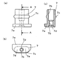
図5に、ケーブル用パッキン7単体の形状を示す。図5(a)はケーブル用パッキン7の平面図、図5(b)はケーブル用パッキン7の正面図、図5(c)は、ケーブル用パッキン7の図5(a)におけるA−A断面図、つまり挿通孔の軸方向の断面図を示している。 FIG. 5 shows the shape of the cable packing 7 alone. 5A is a plan view of the cable packing 7, FIG. 5B is a front view of the cable packing 7, and FIG. 5C is an AA cross section of the cable packing 7 in FIG. 5A. The figure, ie, sectional drawing of the axial direction of an insertion hole is shown.
ケーブル用パッキン7は中央に挿通孔7bが開いている筒状の形状をしている。筒状形状部分の挿通孔7bの軸に直交する断面形状は長円形をしている。筒状の端部には、筒状部分より外形を大きくした係止部7aを形成している。この係止部7aがケーブル用パッキン7を筐体に押し込むときのストッパーとして機能するため、ケーブル用パッキン7を防水に適した最適位置に位置させることができる。
The
また、図5(b)に示したように、係止部7aの下の挿通孔7bの両側はケーブル用パッキン7を筐体の開口部であるパッキン用穴24に押し込む際の押圧スペース7eとして用いる。ここで、ケーブル用パッキン7の筒状形状を長円形筒状形状とする。
Further, as shown in FIG. 5B, both sides of the
この構成により、長円形筒状形状の短手方向の厚さにより筐体の薄型化を達成しつつ、ケーブル用パッキン7を筐体に押し込むときのケーブル用パッキン7に挿通したケーブル5の両側を挿通孔7bの軸方向に押圧する押圧スペースが確保できる。そのため、押圧スペース7eを押すことにより、ケーブル用パッキン7を筐体の挿通孔7bに押し込むことができる。なお、ケーブル用パッキン7の挿通孔7bの断面形状(挿通孔7bの軸に直交する断面形状)は、ケーブル5の断面形状に合わせて、円形形状である。
With this configuration, both sides of the
ケーブル用パッキン7の筒状部分の外表面には第1防水圧入リブである凸部7cを環状に設けている。ここで、凸部7cの挿通孔の軸方向の断面形状は、半円形形状をしている。筒状部分の内表面には第2防水圧入リブである、長方形形状の断面(ただし、角は丸くなっている)の長方形形状断面凸部7dを形成している。
On the outer surface of the cylindrical portion of the cable packing 7, a
ここで、長方形形状断面凸部7dの挿通孔の軸方向の断面形状は、長方形形状の断面(ただし、角は丸くなっている)をしている。この長方形形状断面凸部7dの部分では、内径が挿通孔7bより小さくなっている。また、長方形形状断面凸部7dの挿通孔の軸方向の断面は、長方形形状(ただし、角は丸くなっている)をしている。
Here, the cross-sectional shape in the axial direction of the insertion hole of the rectangular cross-section
この構成により、組み立て時等にケーブル用パッキン7を開口部であるパッキン用穴14、24に挿入する場合には第1防水圧入リブである凸部7cの挿通孔7bの軸方向の断面が半円形形状なので挿入が容易である一方、筐体を開閉する場合等ケーブル5に力が加わった場合でも第2防水圧入リブである長方形形状断面凸部7dの挿通孔7bの軸方向の断面が長方形形状(ただし、角は丸くなっている)なので、接触面積が大きく、確実に防水性を保つことを可能としている。
With this configuration, when the cable packing 7 is inserted into the packing holes 14 and 24, which are openings, at the time of assembly or the like, the axial cross section of the
なお、第2防水圧入リブとして、挿通孔の軸方向の断面形状が長方形形状の断面(ただし、角は丸くなっている)の長方形形状断面凸部7dを説明したが、この代わりに、挿通孔の軸方向の断面形状が台形形状の断面(ただし、角は丸くなっている)の台形形状断面凸部を用いても同様の効果が得られる。
In addition, as the second waterproof press-fitting rib, the cross-sectional shape in the axial direction of the insertion hole has been described as a rectangular cross-section
本発明の実施の形態1では、筒状部分の外表面に設けた第1防水圧入リブである凸部7cを係止部7aから遠い位置に形成し、筒状部分の内表面に設けた第2防水圧入リブである長方形形状断面凸部7dを係止部7aの近い位置に形成し、挿通孔の軸方向について両者が重ならないように離している。
In
このことにより、凸部7cが圧縮されたときの影響ができるだけ長方形形状断面凸部7dに及ばないように、また長方形形状断面凸部7dが圧縮されたときの影響ができるだけ凸部7cに及ばないようにしている。
As a result, the influence when the
すなわち、第1防水圧入リブである凸部7cと前記第2防水圧入リブである長方形形状断面凸部7dとを挿通孔7bの軸方向に互いにずれた位置に設けたので、第1防水圧入リブである凸部7cの変形と第2防水圧入リブである長方形形状断面凸部7dの変形との間の互いの影響を小さくできるので、小さい部品、少ない部品で確実な防水機能を実現した携帯端末装置を提供することができる。
That is, the
また、防水パッキンであるケーブル用パッキン7は、第1防水圧入リブである凸部7cを第2防水圧入リブである長方形形状断面凸部7dよりも係止部7aと反対側の筒状形状の端部に近い位置に設けている。
In addition, the cable packing 7 that is a waterproof packing has a cylindrical shape on the opposite side of the locking
この構成により、凸部7cが内側、すなわちケーブル用パッキン7の係止部7aが外側になるように、ケーブル用パッキン7を筐体の開口部であるパッキン用穴14、24に挿入しておけば、筐体を開閉する場合等ケーブル5に力が加わった場合にケーブル用パッキン7が筐体の開口部であるパッキン用穴14、24から少し抜けかかった状態になったとしても、凸部7cが長方形形状断面凸部7dや係止部7aより内側にあるので、防水性を保つことができ、防水性を高めることができる。
With this configuration, the cable packing 7 can be inserted into the packing holes 14 and 24 that are openings of the housing so that the
また、本発明の実施の形態1で、凸部7cの圧縮量と長方形形状断面凸部7dの圧縮量が互いに影響しないようにしたことは、凸部7cと長方形形状断面凸部7dがそれぞれ所要の密着力で筐体あるいはケーブル5とそれぞれ密着するので、確実に防水できるという利点がある。また、凸部7cの圧縮量と長方形形状断面凸部7dの圧縮量を最終調整していく金型製作上においても、個別に圧縮量を最終調整することができるという利点もある。
In
図6は、ケーブル用防水パッキンの抜け止め部材9単品の斜視図である。抜け止め部材9は略コの字形の部品であり、コの字を形成している溝部9aでケーブル5を覆うように第一の筐体の抜け止め部材用固定溝99に嵌めこまれる。
FIG. 6 is a perspective view of a
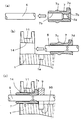
図7に、ケーブル用パッキン7の挿通孔7bにケーブル5を通し、第一の筐体1の開口部であるパッキン用穴14にケーブル用パッキン7を嵌めこんで、抜け止め部材9をケーブル5の上から第一の筐体の抜け止め部材用固定溝99に嵌め込む手順を示す。
In FIG. 7, the
図7(a)は、ケーブル用パッキン7の挿通孔7bにケーブル5を通す前のケーブル用パッキン7とケーブル5の状態を示す。図7(b)は、ケーブル用パッキン7の挿通孔7bにケーブル5を通した後、第一の筐体1のパッキン用穴14にケーブル用パッキン7を嵌め込む寸前の状態を示す。図7(c)は、第一の筐体1のパッキン用穴14にケーブル用パッキン7を嵌め込んだ後、抜け止め部材9をケーブル5の上から第一の筐体の抜け止め部材用固定溝99に嵌め込んだときの状態を示す。
FIG. 7A shows the state of the cable packing 7 and the
図7(b)で示したように、ケーブル用パッキン7の挿通孔7bにケーブル5を通すと、ケーブル用パッキンの第2防水圧入リブである長方形形状断面凸部7dがケーブル5に密着して一体となる。そして図7(b)の左矢印のように、第一の筐体1のパッキン用穴14にケーブル用パッキン7を嵌め込んでいくのであるが、ケーブル用パッキンは図5(b)で示した挿通孔7bの両側の押圧スペース7eを軸方向に押圧すれば、押圧力をケーブル用パッキン7そのものにかけることが出来る。
As shown in FIG. 7B, when the
そのため、図7(c)のようにケーブル用パッキン7そのものを押圧して、ケーブル用パッキン7を第一の筐体の開口部であるパッキン用穴14に嵌め込むことができる。ケーブル用パッキンの第1防水圧入リブである凸部7cは第一の筐体のパッキン用穴14により圧縮されて密着し、第一の筐体1とケーブル用パッキン7の間での水の浸入を防止する。
Therefore, as shown in FIG. 7C, the cable packing 7 itself can be pressed to fit the cable packing 7 into the
なお、第一の筐体のパッキン用穴14の大きさは、ケーブル用パッキン7を押し込んでいく方向にテーパー状に大きくしている。そのため、ケーブル用パッキン7とケーブル5を同時に第一の筐体のパッキン用穴14に一度押し込むと、押し込んだ後はケーブル用パッキン7が抜けにくくなる。
The size of the
また、図7(c)に示したように、係止部7aが第一の筐体のパッキン用穴14の端面に当たるまでケーブル用パッキン7を嵌め込むと、長方形形状断面凸部7dのある筒状部分の外周面も第一の筐体のパッキン用穴14により押圧される。そのため、第一の筐体のパッキン用穴14とケーブル用パッキンの長方形形状断面凸部7dのある筒状部分の外周面が密着して、第一の筐体1とケーブル用パッキン7の間での水の浸入が防止される。
Further, as shown in FIG. 7C, when the cable packing 7 is fitted until the locking
また、ケーブル用パッキンの長方形形状断面凸部7dも更に圧縮されるので、ケーブル用パッキン7とケーブル5の間が更に密着して防水効果が高まる。
Moreover, since the rectangular cross-sectional
なお、ケーブル用パッキン7の材質については、特に説明しなかったが、シリコンゴム等のパッキン材料を用いることが出来る。また、筐体の開口部であるパッキン用穴14、24の形としては、パッキン用穴14、24というように穴として説明したが、パッキン用穴14、24とパッキン保持用溝11、21がつながった一辺が開口した開口穴としてもよい。
The material of the cable packing 7 is not particularly described, but a packing material such as silicon rubber can be used. Further, as the shape of the packing holes 14 and 24 which are the openings of the housing, the packing holes 14 and 24 have been described as holes. However, the packing holes 14 and 24 and the
以上説明したように、本発明の実施の形態1によれば、小さい部品、少ない部品で確実な防水機能を実現した携帯端末装置を提供することができる。
As described above, according to
また、本発明の実施の形態1では、第一の筐体1と第二の筐体2を開閉するタイプの携帯端末装置100を説明したが、本発明は、第一の筐体1に対して第二の筐体2をスライドするタイプの携帯端末装置、第一の筐体1と第二の筐体2を縦方向及び横方向に開閉するタイプの携帯端末装置などにも用いることが出来る。
In the first embodiment of the present invention, the portable
本発明は、折り畳み式携帯電話機をはじめ、折り畳み式ゲーム機など、二つの筐体を接続する防水構造付き携帯端末装置に適用することが出来る。また、本発明の防水パッキンは、一つの筐体を接続する防水構造付き携帯端末装置にも適用することが出来る。 The present invention can be applied to a portable terminal device with a waterproof structure that connects two housings, such as a foldable mobile phone and a foldable game machine. The waterproof packing of the present invention can also be applied to a portable terminal device with a waterproof structure that connects one housing.
1 第一の筐体
2 第二の筐体
3 連結部
5 ケーブル
7 ケーブル用パッキン(防水パッキン)
7a 係止部
7b 挿通孔
7c 凸部(第1防水圧入リブ)
7d 長方形形状断面凸部(第2防水圧入リブ)
7e 押圧スペース
9 抜け止め部材
14,24 パッキン用穴(開口部)
DESCRIPTION OF
7d Rectangular cross section convex part (second waterproof press-fit rib)
7e Pressing
Claims (6)
前記開口部を通して前記筐体内の電子回路と他の電子回路とを電気的に接続するケーブルと、
前記ケーブルが挿通される挿通孔が貫通形成されて前記開口部に挿入される防水パッキンと、を備え、
前記防水パッキンは、筒状形状であって、前記筒状形状の外側に第1防水圧入リブと、前記筒状形状の内側に第2防水圧入リブと、を有し、前記第1防水圧入リブと前記第2防水圧入リブとは前記挿通孔の軸方向に互いにずれた位置に設けられた
防水構造付き携帯端末装置。 A housing having an opening;
A cable for electrically connecting the electronic circuit in the housing and the other electronic circuit through the opening;
A waterproof packing in which an insertion hole through which the cable is inserted is formed and inserted into the opening, and
The waterproof packing has a cylindrical shape, and includes a first waterproof press-fitting rib on the outside of the cylindrical shape, and a second waterproof press-fit rib on the inside of the cylindrical shape, and the first waterproof press-fit rib. And the second waterproof press-fitting rib are portable terminal devices with a waterproof structure provided at positions shifted from each other in the axial direction of the insertion hole.
前記防水パッキンの前記第2防水圧入リブは、前記挿通孔の軸方向の断面が長方形形状又は台形形状(ただし、角は丸くなっている)である、
請求項1記載の防水構造付き携帯端末装置。 The first waterproof press-fitting rib of the waterproof packing has a semicircular cross section in the axial direction of the insertion hole,
The second waterproof press-fitting rib of the waterproof packing has a rectangular or trapezoidal cross section in the axial direction of the insertion hole (however, the corners are rounded).
The portable terminal device with a waterproof structure according to claim 1.
請求項1又は請求項2記載の防水構造付き携帯端末装置。 The portable terminal device with waterproof structure according to claim 1 or 2, wherein the waterproof packing has a locking portion at an end of the cylindrical shape.
請求項3記載の防水構造付き携帯端末装置。 4. The portable waterproof structure according to claim 3, wherein the waterproof packing is provided with the first waterproof press-fitting rib at a position closer to the end of the cylindrical shape on the opposite side of the locking part than the second waterproof press-fitting rib. Terminal device.
請求項1乃至請求項4のいずれか1項に記載の防水構造付き携帯端末装置。 The portable terminal device with a waterproof structure according to any one of claims 1 to 4, wherein the cylindrical shape of the waterproof packing is an oval cylindrical shape.
Priority Applications (4)
| Application Number | Priority Date | Filing Date | Title |
|---|---|---|---|
| JP2008159973A JP4438883B2 (en) | 2008-06-19 | 2008-06-19 | Portable terminal device with waterproof structure |
| PCT/JP2009/000390 WO2009153898A1 (en) | 2008-06-19 | 2009-02-02 | Portable terminal device with waterproof structure |
| CN2009801282426A CN102100133A (en) | 2008-06-19 | 2009-02-02 | Portable terminal device with waterproof structure |
| US12/999,870 US20110110022A1 (en) | 2008-06-19 | 2009-02-02 | Portable terminal device with waterproof structure |
Applications Claiming Priority (1)
| Application Number | Priority Date | Filing Date | Title |
|---|---|---|---|
| JP2008159973A JP4438883B2 (en) | 2008-06-19 | 2008-06-19 | Portable terminal device with waterproof structure |
Publications (3)
| Publication Number | Publication Date |
|---|---|
| JP2010004202A true JP2010004202A (en) | 2010-01-07 |
| JP2010004202A5 JP2010004202A5 (en) | 2010-02-18 |
| JP4438883B2 JP4438883B2 (en) | 2010-03-24 |
Family
ID=41433825
Family Applications (1)
| Application Number | Title | Priority Date | Filing Date |
|---|---|---|---|
| JP2008159973A Active JP4438883B2 (en) | 2008-06-19 | 2008-06-19 | Portable terminal device with waterproof structure |
Country Status (4)
| Country | Link |
|---|---|
| US (1) | US20110110022A1 (en) |
| JP (1) | JP4438883B2 (en) |
| CN (1) | CN102100133A (en) |
| WO (1) | WO2009153898A1 (en) |
Cited By (1)
| Publication number | Priority date | Publication date | Assignee | Title |
|---|---|---|---|---|
| JP2011228892A (en) * | 2010-04-19 | 2011-11-10 | Panasonic Corp | Foldable electronic apparatus |
Families Citing this family (8)
| Publication number | Priority date | Publication date | Assignee | Title |
|---|---|---|---|---|
| TWI430530B (en) * | 2010-08-02 | 2014-03-11 | A cable - like flexible circuit cable with a waterproof section | |
| JP2013003487A (en) * | 2011-06-21 | 2013-01-07 | Panasonic Liquid Crystal Display Co Ltd | Display device |
| KR101850150B1 (en) * | 2011-07-13 | 2018-04-19 | 삼성전자주식회사 | Portable communication device |
| KR101892030B1 (en) | 2012-03-21 | 2018-08-29 | 삼성전자주식회사 | Apparatus for waterproofing battery cover in portable terminal |
| KR101929879B1 (en) * | 2012-04-09 | 2019-03-15 | 삼성전자주식회사 | Portable terminal |
| KR102604966B1 (en) * | 2017-02-24 | 2023-11-22 | 엘지전자 주식회사 | Mobile terminal |
| KR102369614B1 (en) * | 2017-09-05 | 2022-03-03 | 삼성전자주식회사 | electronic device including waterproof structure |
| US11092996B2 (en) * | 2019-08-20 | 2021-08-17 | Getac Technology Corporation | Electronic device |
Family Cites Families (8)
| Publication number | Priority date | Publication date | Assignee | Title |
|---|---|---|---|---|
| JPS509593Y1 (en) * | 1970-12-28 | 1975-03-24 | ||
| JPS5987186A (en) * | 1982-11-12 | 1984-05-19 | Nec Corp | Supporting mechanism for print hammer and platen |
| JPS5987186U (en) * | 1982-12-03 | 1984-06-13 | 株式会社三ツ葉電機製作所 | grommet |
| JPS63150429A (en) * | 1986-12-12 | 1988-06-23 | Hitachi Ltd | Back-up dust removing apparatus |
| JPH0313941Y2 (en) * | 1987-03-24 | 1991-03-28 | ||
| JP2002164671A (en) * | 2000-11-28 | 2002-06-07 | Canon Inc | Method and structure for forming output lead take out structure, output lead take out unit, solar cell module, solar cell array |
| US7251512B2 (en) * | 2002-05-13 | 2007-07-31 | Nec Corporation | Water-proof collapsible cellular terminal apparatus |
| JP4486461B2 (en) * | 2004-09-27 | 2010-06-23 | 富士通株式会社 | Portable electronic device |
-
2008
- 2008-06-19 JP JP2008159973A patent/JP4438883B2/en active Active
-
2009
- 2009-02-02 CN CN2009801282426A patent/CN102100133A/en active Pending
- 2009-02-02 US US12/999,870 patent/US20110110022A1/en not_active Abandoned
- 2009-02-02 WO PCT/JP2009/000390 patent/WO2009153898A1/en active Application Filing
Cited By (1)
| Publication number | Priority date | Publication date | Assignee | Title |
|---|---|---|---|---|
| JP2011228892A (en) * | 2010-04-19 | 2011-11-10 | Panasonic Corp | Foldable electronic apparatus |
Also Published As
| Publication number | Publication date |
|---|---|
| CN102100133A (en) | 2011-06-15 |
| JP4438883B2 (en) | 2010-03-24 |
| WO2009153898A1 (en) | 2009-12-23 |
| US20110110022A1 (en) | 2011-05-12 |
Similar Documents
| Publication | Publication Date | Title |
|---|---|---|
| JP4438883B2 (en) | Portable terminal device with waterproof structure | |
| US20110247924A1 (en) | Key button mechanism and electronic device using the same | |
| KR101966259B1 (en) | Sealing appratus for a electronic device | |
| JP2009059586A (en) | Waterproofing terminal structure, and electronic equipment | |
| JP2011071876A (en) | Mobile terminal device and waterproof casing structure | |
| JP2004214927A (en) | Portable electronic device | |
| JP2008218633A (en) | Waterproof structure of electronic equipment | |
| JP2012059479A (en) | Water-proof attachment structure of connectors | |
| JP2008091091A (en) | Electronic apparatus | |
| JP2005348341A (en) | Portable electronic equipment | |
| JP4916388B2 (en) | Portable electronic devices | |
| JP2006287313A (en) | Waterproof structure of electronic apparatus | |
| JP4945804B2 (en) | Connector structure and terminal device | |
| JP2010050306A (en) | Waterproof structure, and electronic device | |
| JP4953941B2 (en) | Portable electronic devices | |
| JP2010114126A (en) | Waterproof structure and terminal device | |
| JP2010067838A (en) | Electronic apparatus | |
| JP2010129931A (en) | Electric apparatus, and method of manufacturing the same | |
| JP2007201789A (en) | Portable electronic equipment | |
| JP2013222597A (en) | Jack structure | |
| JP2010086672A (en) | Connector waterproof structure and electronic equipment | |
| JP2008085140A (en) | Waterproof construction of electronic device | |
| KR102337132B1 (en) | Receptacle Connector | |
| JP2012007697A (en) | Packing and waterproof structure | |
| JP2008153793A (en) | Cable positioning structure of folding type electronic equipment and folding type electronic equipment |
Legal Events
| Date | Code | Title | Description |
|---|---|---|---|
| A521 | Request for written amendment filed |
Free format text: JAPANESE INTERMEDIATE CODE: A523 Effective date: 20091111 |
|
| A621 | Written request for application examination |
Free format text: JAPANESE INTERMEDIATE CODE: A621 Effective date: 20091111 |
|
| A871 | Explanation of circumstances concerning accelerated examination |
Free format text: JAPANESE INTERMEDIATE CODE: A871 Effective date: 20091113 |
|
| TRDD | Decision of grant or rejection written | ||
| A975 | Report on accelerated examination |
Free format text: JAPANESE INTERMEDIATE CODE: A971005 Effective date: 20091208 |
|
| RD01 | Notification of change of attorney |
Free format text: JAPANESE INTERMEDIATE CODE: A7421 Effective date: 20091214 |
|
| A01 | Written decision to grant a patent or to grant a registration (utility model) |
Free format text: JAPANESE INTERMEDIATE CODE: A01 Effective date: 20091215 |
|
| A01 | Written decision to grant a patent or to grant a registration (utility model) |
Free format text: JAPANESE INTERMEDIATE CODE: A01 |
|
| A61 | First payment of annual fees (during grant procedure) |
Free format text: JAPANESE INTERMEDIATE CODE: A61 Effective date: 20091228 |
|
| FPAY | Renewal fee payment (event date is renewal date of database) |
Free format text: PAYMENT UNTIL: 20130115 Year of fee payment: 3 |
|
| R151 | Written notification of patent or utility model registration |
Ref document number: 4438883 Country of ref document: JP Free format text: JAPANESE INTERMEDIATE CODE: R151 |
|
| FPAY | Renewal fee payment (event date is renewal date of database) |
Free format text: PAYMENT UNTIL: 20130115 Year of fee payment: 3 |
|
| FPAY | Renewal fee payment (event date is renewal date of database) |
Free format text: PAYMENT UNTIL: 20130115 Year of fee payment: 3 |