JP2010004088A - Communication system, network apparatus, and network connection method used for them - Google Patents
Communication system, network apparatus, and network connection method used for them Download PDFInfo
- Publication number
- JP2010004088A JP2010004088A JP2008158586A JP2008158586A JP2010004088A JP 2010004088 A JP2010004088 A JP 2010004088A JP 2008158586 A JP2008158586 A JP 2008158586A JP 2008158586 A JP2008158586 A JP 2008158586A JP 2010004088 A JP2010004088 A JP 2010004088A
- Authority
- JP
- Japan
- Prior art keywords
- network
- virtual router
- address
- networks
- virtual
- Prior art date
- Legal status (The legal status is an assumption and is not a legal conclusion. Google has not performed a legal analysis and makes no representation as to the accuracy of the status listed.)
- Granted
Links
Images


Abstract
Description
本発明は通信システム、ネットワーク装置及びそれらに用いるネットワーク接続方法に関し、特にアドレスが重複する可能性のあるネットワークを接続する装置に関する。 The present invention relates to a communication system, a network device, and a network connection method used therefor, and more particularly to a device for connecting networks having a possibility of overlapping addresses.
本発明に関連するトンネルについて図6を参照して説明する。図6には、モバイルIP(Internet Protocol)におけるトンネル(IPinIPトンネル)を示している。 A tunnel related to the present invention will be described with reference to FIG. FIG. 6 shows a tunnel (IPinIP tunnel) in mobile IP (Internet Protocol).
図6において、本発明に関連する通信システムは、HA(Home Agent:ホームエージェント)6と、FA(Foreign Agent:外部エージェント)7−1,7−2と、ネットワーク200とから構成されている。ネットワーク200には、CN(Corresponding Node)#11,#21,#31,#41が存在し、FA7−1,7−2の配下には、MS(Mobile Station)#11,#12,#21,#22,#31,#32,#41,#42が存在する。
In FIG. 6, the communication system related to the present invention includes an HA (Home Agent) 6, FAs (Foreign Agents) 7-1 and 7-2, and a
モバイルIPでは、事前にMS#11,#12,#21,#22,#31,#32,#41,#42がFA7−1,7−2を経由してのRRQ(Registration Request)を送信する。 In Mobile IP, MS # 11, # 12, # 21, # 22, # 31, # 32, # 41, # 42 transmit RRQ (Registration Request) via FA 7-1, 7-2 in advance. To do.
HA6は、そのRRQを受信後、FA7−1,7−2のCoA(Care of Address)#1,#2とIPinIPトンネルを作成し、RRP(Registration Reply)をMS#11,#12,#21,#22,#31,#32,#41,#42に返却する。これによって、HA6は、MS#11,#12,#21,#22,#31,#32,#41,#42がどのFA7−1,7−2の配下にいるかを把握する。
After receiving the RRQ, the
上記の通信システムにおいて、FA7−1,7−2及びHA6は、仮想ルータ(VR:Virtual Router)に対応しておらず、ルーティングテーブルを装置で一つ持つのみである(例えば、特許文献1参照)。 In the communication system, the FAs 7-1, 7-2, and HA6 do not correspond to a virtual router (VR) and have only one routing table in the apparatus (for example, see Patent Document 1). ).
このため、全ネットワーク構成においては、アドレスの重複が許容されず、ユニークなアドレスが各ノードに振られていることを前提にルーティングを実施する。 For this reason, in all network configurations, address duplication is not allowed, and routing is performed on the assumption that a unique address is assigned to each node.
トンネルインタフェースも、ただ一つのネットワークにのみ所属し、Inner IPアドレス(内側IPアドレス)とOuter IPアドレス(外側IPアドレス)とが異なる仮想ルータ(VR)に所属することはない。 The tunnel interface belongs to only one network, and the Inner IP address (inner IP address) and the Outer IP address (outer IP address) do not belong to different virtual routers (VR).
このため、各ネットワークのIPアドレスは、ユニークでなければならず、それぞれのネットワークにて、プライベートアドレスを使用していると、IPアドレスが重複する可能性がある。よって、そのような場合には、ユニークになるようにアドレスを変更する必要がある。 For this reason, the IP address of each network must be unique. If a private address is used in each network, the IP address may be duplicated. Therefore, in such a case, it is necessary to change the address so as to be unique.
本発明に関連する仮想ルータ(VR)について図7を参照して説明する。図7において、ルータ(Router)8は、仮想ルータ(VR)81,82に対応しているが、仮想ルータ(VR)81のルーティングテーブル(図示せず)と仮想ルータ(VR)82のルーティングテーブル(図示せず)とは全く別物である。
A virtual router (VR) related to the present invention will be described with reference to FIG. In FIG. 7, the
また、仮想ルータ(VR)81はネットワーク#1,#3を収容し、仮想ルータ(VR)82はネットワーク#2,#4を収容し、それぞれのネットワーク#1,#3とネットワーク#2,#4とを結ぶものはなく、2台のルータがあることとほぼ同一である。このような構成では、異なるネットワークを跨いで通信を行うことはできない。
The virtual router (VR) 81 accommodates
通信業者等が構築しているネットワークや機器を、別の通信業者が共有する場合には、それぞれがプライベートIPアドレスを使用している等、一部アドレスが重複する場合においてもエンドツーエンド(End−to−End)での到達性を確保する必要がある。 If another network operator shares a network or device built by a network operator, etc., end-to-end (End) even if some addresses overlap, such as using private IP addresses. It is necessary to ensure reachability in (-to-End).
この場合には、アドレス重複を許容するために、仮想ルータ(VR)に対応した装置とすること、またアドレス重複のあり得る、他事業者の提供するネットワークを経由してエンドツーエンドの到達性を確保することから、仮想ルータ(VR)を接続する必要がある。 In this case, in order to allow address duplication, a device corresponding to a virtual router (VR) should be used, and end-to-end reachability via a network provided by another operator that may have address duplication. Therefore, it is necessary to connect a virtual router (VR).
本発明に関連するトンネルでは、IPトンネルの場合、Outer IPアドレス(外側IPアドレス)とInner IPアドレス(内側IPアドレス)とがそれぞれユニークな1つのアドレス空間に所属している。 In the tunnel related to the present invention, in the case of an IP tunnel, the Outer IP address (outer IP address) and the Inner IP address (inner IP address) belong to one unique address space.
そのため、上記のIPトンネルでは、グローバルアドレスならばアドレス重複がないが、プライベートアドレスを使用する場合、既存のプライベートアドレス空間と別の既存のプライベートアドレス空間とがInner/Outer IPアドレスとなる場合において、アドレスが重複する可能性があり、どちらかのIPアドレス割り振りを変更する必要がある。 Therefore, in the above IP tunnel, there is no address duplication if it is a global address, but when a private address is used, when an existing private address space and another existing private address space become an Inner / Outer IP address, Addresses may be duplicated and either IP address allocation needs to be changed.
しかしながら、既存のネットワーク構成を変更するのは、コストが高いため、アドレスを変更せずにネットワークを構築する手段が求められている。上記の特許文献1に記載の技術でも、上記と同様の課題がある。
However, changing the existing network configuration is expensive, and there is a need for means for building a network without changing the address. The technique described in
そこで、本発明の目的は上記の問題点を解消し、IPアドレスの重複の可能性があるネットワークを接続して通信することができる通信システム、ネットワーク装置及びそれらに用いるネットワーク接続方法を提供することにある。 Therefore, an object of the present invention is to provide a communication system, a network device, and a network connection method used for them, which can solve the above-mentioned problems and can connect and communicate with networks having the possibility of overlapping IP addresses. It is in.
本発明による通信システムは、アドレスが重複する可能性のあるネットワークを接続する通信システムであって、
前記ネットワークを別々の異なる第1及び第2のネットワークとして分離し、
前記第1のネットワークに対応する第1のルーティングテーブルを持つ第1の仮想ルータと、前記第2のネットワークに対応する第2のルーティングテーブルを持つ第2の仮想ルータと、前記第1の仮想ルータと前記第2の仮想ルータとを接続するトンネルインタフェースとを含むネットワーク装置を備えている。
A communication system according to the present invention is a communication system for connecting networks that may have overlapping addresses,
Separating the networks as separate different first and second networks;
A first virtual router having a first routing table corresponding to the first network; a second virtual router having a second routing table corresponding to the second network; and the first virtual router. And a tunnel interface for connecting the second virtual router.
本発明によるネットワーク装置は、アドレスが重複する可能性のあるネットワークを接続するネットワーク装置であって、
前記ネットワークを別々の異なる第1及び第2のネットワークとして分離し、
前記第1のネットワークに対応する第1のルーティングテーブルを持つ第1の仮想ルータと、前記第2のネットワークに対応する第2のルーティングテーブルを持つ第2の仮想ルータと、前記第1の仮想ルータと前記第2の仮想ルータとを接続するトンネルインタフェースとを備えている。
A network device according to the present invention is a network device that connects networks that may have overlapping addresses,
Separating the networks as separate different first and second networks;
A first virtual router having a first routing table corresponding to the first network; a second virtual router having a second routing table corresponding to the second network; and the first virtual router. And a tunnel interface for connecting the second virtual router.
本発明によるネットワーク接続方法は、アドレスが重複する可能性のあるネットワークを接続する通信システムに用いるネットワーク接続方法であって、
前記ネットワークを別々の異なる第1及び第2のネットワークとして分離し、
ネットワーク装置に、前記第1のネットワークに対応する第1のルーティングテーブルを持つ第1の仮想ルータと、前記第2のネットワークに対応する第2のルーティングテーブルを持つ第2の仮想ルータとをトンネルインタフェースにて接続している。
A network connection method according to the present invention is a network connection method used in a communication system for connecting networks that may have overlapping addresses,
Separating the networks as separate different first and second networks;
A tunnel interface includes a first virtual router having a first routing table corresponding to the first network and a second virtual router having a second routing table corresponding to the second network. Connected with.
本発明は、上記のような構成及び動作とすることで、IPアドレスの重複の可能性があるネットワークを接続して通信することことができるという効果が得られる。 By adopting the above-described configuration and operation, the present invention can obtain an effect that communication can be performed by connecting networks having a possibility of overlapping IP addresses.
次に、本発明の実施の形態について図面を参照して説明する。まず、本発明による通信システムの概要について説明する。本発明による通信システムは、IP(Internet Protocol)アドレスの重複の可能性がある異なるネットワークを経由してエンドツーエンド(End−to−End)の通信を提供することを特徴としている。 Next, embodiments of the present invention will be described with reference to the drawings. First, an outline of a communication system according to the present invention will be described. The communication system according to the present invention is characterized in that it provides end-to-end communication via different networks with the possibility of overlapping IP (Internet Protocol) addresses.
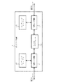
図1は本発明によるネットワーク装置の構成例を示すブロック図である。図1において、ネットワーク装置1は、第1のネットワーク(図示せず)に接続される仮想ルータ(VR:Virtual Router)機能11と、第2のネットワーク(図示せず)に接続される仮想ルータ(VR)機能14と、仮想ルータ(VR)機能11,14各々に対応するルーティングテーブル12,15と、仮想ルータ(VR)機能11と仮想ルータ(VR)機能14とを接続するトンネルインタフェース13とを含んで構成されている。
FIG. 1 is a block diagram showing a configuration example of a network device according to the present invention. In FIG. 1, a
ネットワーク装置1では、第1のネットワークと第2のネットワークとを収容しており、それぞれ別々のルーティングテーブル12,15を持っている。また、ネットワーク装置1では、仮想ルータ(VR)機能11と仮想ルータ(VR)機能14とをトンネルインタフェース13にて接続する。
The
ネットワーク装置1においては、Outer IPアドレス(外側IPアドレス)が仮想ルータ(VR)機能11に所属し、Inner IPアドレス(内側IPアドレス)が仮想ルータ(VR)機能14に所属する。
In the
本発明では、Inner IPアドレスとOuter IPアドレスとが異なる仮想ルータ(VR)機能11,14に所属するトンネルインタフェース13によって第1のネットワークと第2のネットワークとを接続し、Inner IPアドレスとOuter IPアドレスとが異なる仮想ルータ(VR)機能11,14のルーティングテーブル12,15でそれぞれルーティングしている。これによって、本発明では、異なるネットワークを経由しての仮想ルータ(VR)を跨いだ通信が可能となる。
In the present invention, the first network and the second network are connected by the
図2は本発明の第1の実施の形態による通信システムの構成例を示すブロック図である。図2において、本発明の第1の実施の形態による通信システムは、ネットワーク101[仮想ルータ(VR)3−1]と、ネットワーク102[仮想ルータ(VR)3−2]と、ネットワーク103[仮想ルータ(VR)3−1]と、ゲートウェイ(GW)2−1と、ゲートウェイ(GW)2−2とから構成されている。 FIG. 2 is a block diagram showing a configuration example of the communication system according to the first exemplary embodiment of the present invention. 2, the communication system according to the first exemplary embodiment of the present invention includes a network 101 [virtual router (VR) 3-1], a network 102 [virtual router (VR) 3-2], and a network 103 [virtual]. Router (VR) 3-1], gateway (GW) 2-1, and gateway (GW) 2-2.
ゲートウェイ(GW)2−1及びゲートウェイ(GW)2−2は、図1に示すネットワーク装置1と同様に、それぞれ仮想ルータ(VR)の機能(図示せず)を持っている。
Each of the gateway (GW) 2-1 and the gateway (GW) 2-2 has a virtual router (VR) function (not shown), like the
ゲートウェイ(GW)2−1では、ネットワーク101とネットワーク102とを収容しており、それぞれ別々のルーティングテーブル22−1,23−1を持っている。
The gateway (GW) 2-1 accommodates the
また、ゲートウェイ(GW)2−1では、仮想ルータ(VR)3−1と仮想ルータ(VR)3−2とをトンネルインタフェース21−1にて接続する。ゲートウェイ(GW)2−1においては、Outer IPアドレス(外側IPアドレス)が仮想ルータ(VR)3−1に所属し、Inner IPアドレス(内側IPアドレス)が仮想ルータ(VR)3−2に所属する。 In the gateway (GW) 2-1, the virtual router (VR) 3-1 and the virtual router (VR) 3-2 are connected by the tunnel interface 21-1. In the gateway (GW) 2-1, the Outer IP address (outer IP address) belongs to the virtual router (VR) 3-1, and the Inner IP address (inner IP address) belongs to the virtual router (VR) 3-2. To do.
上記と同様に、ゲートウェイ(GW)2−2では、ネットワーク102とネットワーク103とを収容しており、それぞれ別々のルーティングテーブル22−2,23−2を持っている。
Similarly to the above, the gateway (GW) 2-2 accommodates the
ゲートウェイ(GW)2−2では、仮想ルータ(VR)3−2と仮想ルータ(VR)3−1とをトンネルインタフェース21−2にて接続する。ゲートウェイ(GW)2−2においては、Outer IPアドレスが仮想ルータ(VR)3−1に所属し、Inner IPアドレスが仮想ルータ(VR)3−2に所属する。 In the gateway (GW) 2-2, the virtual router (VR) 3-2 and the virtual router (VR) 3-1 are connected by the tunnel interface 21-2. In the gateway (GW) 2-2, the Outer IP address belongs to the virtual router (VR) 3-1, and the Inner IP address belongs to the virtual router (VR) 3-2.
図3は本発明に用いられるパケットのフォーマット例を示す図であり、図4は本発明による通信システムの動作を示すシーケンスチャートである。これら図1〜図4を参照して本発明による通信システムの動作について説明する。 FIG. 3 is a diagram showing a packet format example used in the present invention, and FIG. 4 is a sequence chart showing the operation of the communication system according to the present invention. The operation of the communication system according to the present invention will be described with reference to FIGS.
ネットワーク103に所属のIPアドレスAddr1−2から、ネットワーク101に所属のIPアドレスAddr1−1へIP通信を実施する際には、以下のような動作となる。
When IP communication is performed from the IP address Addr1-2 belonging to the
(1)ネットワーク103に所属のIPアドレスAddr1−2を持つホスト(図示せず)は、パケットをゲートウェイ(GW)2−2のインタフェースに向けて送信する(図4のa1)。
(1) A host (not shown) having an IP address Addr1-2 belonging to the
(2)ゲートウェイ(GW)2−2のルーティングテーブル23−2では、IPアドレスAddr1−1宛てのパケットのnexthopがトンネルインタフェース21−2への出力となっている。そのため、ゲートウェイ(GW)2−2において、パケットは、トンネルインタフェース21−2に渡される(図4のa2)。 (2) In the routing table 23-2 of the gateway (GW) 2-2, the next of the packet addressed to the IP address Addr1-1 is an output to the tunnel interface 21-2. Therefore, in the gateway (GW) 2-2, the packet is passed to the tunnel interface 21-2 (a2 in FIG. 4).
(3)トンネルインタフェース21−2は、Outer IPヘッダのカプセル化処理(Encapsulation)以外に、仮想ルータ(VR)を跨ぐ機能を持っている。つまり、トンネルインタフェース21−2は、図3に示すように、仮想ルータ(VR)3−1のネットワークに所属するInner IPアドレスに仮想ルータ(VR)3−2のネットワークに所属するOuter IPアドレスをカプセル化する(図4のa3)。 (3) The tunnel interface 21-2 has a function of straddling the virtual router (VR) in addition to the encapsulation process (Encapsulation) of the Outer IP header. That is, as shown in FIG. 3, the tunnel interface 21-2 sets the Outer IP address belonging to the network of the virtual router (VR) 3-2 to the Inner IP address belonging to the network of the virtual router (VR) 3-1. Encapsulate (a3 in FIG. 4).
(4)Outer IPアドレスのカプセル化後、パケットは、ゲートウェイ(GW)2−2のルーティングテーブル22−2に基づいてルーティングされ(図4のa4)、ゲートウェイ(GW)2−1のインタフェースに向けて送信される(図4のa5)。 (4) After encapsulation of the Outer IP address, the packet is routed based on the routing table 22-2 of the gateway (GW) 2-2 (a4 in FIG. 4), and directed to the interface of the gateway (GW) 2-1. Is transmitted (a5 in FIG. 4).
(5)ゲートウェイ(GW)2−1では、そのパケットをIPアドレスAddr1−1にて受信し、Outer IPアドレスをデカプセル化する(図4のa6)。この場合、仮想ルータ(VR)3−2のOuter IP(Addr1−1,Addr1−2)のトンネルインタフェース21−1は、仮想ルータ(VR)3−1に接続されている。そのため、ゲートウェイ(GW)2−1では、Inner IPパケットがトンネルインタフェース21−1にて仮想ルータ(VR)3−1へ送信される(図4のa7)。 (5) The gateway (GW) 2-1 receives the packet at the IP address Addr1-1 and decapsulates the Outer IP address (a6 in FIG. 4). In this case, the tunnel interface 21-1 of the Outer IP (Addr1-1, Addr1-2) of the virtual router (VR) 3-2 is connected to the virtual router (VR) 3-1. Therefore, in the gateway (GW) 2-1, the Inner IP packet is transmitted to the virtual router (VR) 3-1 through the tunnel interface 21-1 (a7 in FIG. 4).
(6)ゲートウェイ(GW)1−1の仮想ルータ(VR)3−1では、Inner IPアドレスがルーティングテーブル22−1にてルーティングされ(図4のa8)、IPアドレスAddr1−1を持つホスト(図示せず)に転送される(図4のa9)。 (6) In the virtual router (VR) 3-1 of the gateway (GW) 1-1, the Inner IP address is routed in the routing table 22-1 (a 8 in FIG. 4), and the host having the IP address Addr 1-1 ( (A9 in FIG. 4).
このように、本実施の形態では、Inner IPアドレスとOuter IPアドレスとが異なる仮想ルータ(VR)に所属するトンネルインタフェースによってネットワークを接続し、Inner IPアドレスとOuter IPアドレスとが異なる仮想ルータ(VR)のルーティングテーブルでルーティングすることで、異なるネットワークを経由しての仮想ルータ(VR)を跨いだ通信が可能となる。 As described above, in this embodiment, a network is connected by a tunnel interface belonging to a virtual router (VR) in which the Inner IP address and the Outer IP address are different, and the virtual router (VR) in which the Inner IP address and the Outer IP address are different. ), It is possible to communicate across virtual routers (VR) via different networks.
本実施の形態では、アドレスが重複する可能性のあるネットワークを別々の異なるネットワークとして分離し(ネットワーク101,102)、一つの装置[ゲートウェイ(GW)2−1]上において、それぞれ異なるルーティングテーブル(ルーティングテーブル22−1,23−1)を持つ仮想ルータ[仮想ルータ(VR)3−1,3−2]に対応させた上で、それぞれの仮想ルータ[仮想ルータ(VR)3−1,3−2]をトンネルインタフェース21−1にて結ぶことで、カプセル化されたパケットが、アドレスが重複する可能性のある異なるネットワーク(ネットワーク101,102)を経由して、自身のネットワークに到達する手段を提供している。
In the present embodiment, networks that may have overlapping addresses are separated as different networks (
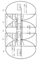
図5は本発明の第2の実施の形態による通信システムの構成例を示すブロック図である。図5においては、本発明の第2の実施の形態としてのネットワーク構成と、各装置の仮想ルータ(VR)とを示している。 FIG. 5 is a block diagram showing a configuration example of a communication system according to the second exemplary embodiment of the present invention. FIG. 5 shows a network configuration and a virtual router (VR) of each device as a second embodiment of the present invention.
図5において、本発明の第2の実施の形態によるネットワーク構成は、HA(Home Agent:ホームエージェント)4−1,4−2と、FA(Foreign Agent:外部エージェント)5−1,5−2とを含んでおり、MobileIPを使用して、サービスネットワーク(Service Network)#1〜#4[ISP(Internet Service Provider)等]に存在するCN(Corresponding Node)#11,#21,#31,#41からFA5−1,5−2の配下に存在するMS(Mobile Station)#11,#12,#21,#22,#31,#32,#41,#42への通信経路を示している。 In FIG. 5, the network configuration according to the second embodiment of the present invention includes HA (Home Agent) 4-1 and 4-2, and FA (Foreign Agent) 5-1 and 5-2. And using MobileIP, CN (Corresponding Node) # 11, # 21, # 31, # 31 existing in service networks (Service Network) # 1 to # 4 [Internet Service Provider (ISP), etc.] 41 shows communication paths from MS (Mobile Station) # 11, # 12, # 21, # 22, # 31, # 32, # 41, # 42 existing under the control of FA5-1, 5-2. .
HA4−1は、仮想ルータVR#11,VR#12,VR#21のネットワークに所属しており、それぞれのネットワーク毎に別々の仮想ルータ(ルーティングテーブル)(図示せず)を持っている。
The HA 4-1 belongs to the networks of the virtual
また、FA5−1は、仮想ルータVR#21,VR#22,VR#31,VR#32,VR#33のネットワークに所属しており、ネットワーク毎に別々の仮想ルータ(ルーティングテーブル)(図示せず)を持っている。
The FA 5-1 belongs to a network of virtual
さらに、HA4−1は、ホームエージェントアドレス(Home Agent Address)HA#1とそのHome link#1を持ち、ホームエージェントアドレスHA#2とそのHome link#2を持っている。
Further, the HA 4-1 has a home agent address (Home Agent Address)
ホームエージェントアドレスHA#1,HA#2は、仮想ルータVR#21のネットワークに所属しており、Homelink#1,Homelink#2は、それぞれ仮想ルータVR#11,VR#12のネットワークに所属している。
Home agent addresses
このようにすることで、それぞれの仮想ルータ(VR)間でのアドレスの重複を可能とする。つまり、本構成では、それぞれの仮想ルータ(VR)のネットワークが「192.168.1.0/24」に所属することが可能となる。 In this way, it is possible to overlap addresses between the virtual routers (VR). That is, in this configuration, each virtual router (VR) network can belong to “192.168.1.0/24”.
ここでは、CN#11が「192.168.1.200」、Homelink#1が「192.168.1.0/25」、HA#1が「192.168.1.200」、CoA(Care of Address)#1が「192.168.1.10」、MS#11が「192.168.1.10」とする。
Here,
これらは、ASN(Access Service Network)、CSN(Connectivity Service Network)、Serviceネットワークの提供者が、それぞれプライベートアドレスを使用することでIPアドレスの重複が発生する可能性があるため、それを想定したアドレス割り振りの構成としている。 These are addresses that IP address duplication may occur when providers of ASN (Access Service Network), CSN (Connectivity Service Network), and Service network use private addresses, respectively. Allocation configuration is used.
次に、図5におけるCN#11がMS#11との通信を実現するまでの動作について説明する。
Next, an operation until
モバイルIPでは、事前にMS(MN)がFAを経由してのRRQ(Registration Request)を送信し、HAがそれを受信後、FAのCoAとIPinIPトンネルを作成し、RRP(Registration Reply)を返却することで、MSがどのFAの配下にいるかをHAが把握している。これらの動作は、モバイルIPとして一般的な動作であり、本発明とは直接関係しないので、その詳細な説明については省略する。 In Mobile IP, MS (MN) sends RRQ (Registration Request) via FA in advance, HA receives it, creates FA CoA and IPinIP tunnel, and returns RRP (Registration Reply) By doing so, the HA knows which FA the MS is under. These operations are general operations for the mobile IP and are not directly related to the present invention, and thus detailed description thereof is omitted.
HA4−1,4−2には、binding cacheが存在しており、HA4−1,4−2とFA5−1,5−2との間にトンネルが存在した後の動作について説明する。 HA 4-1 and 4-2 have a binding cache, and the operation after a tunnel exists between HA 4-1 and 4-2 and FA 5-1 and 5-2 will be described.
(1)CN#11はHomelink#1のサブネットに存在するはずのMS#11に対してパケットを送信する。この時、IPヘッダの送信元アドレスはCN#11(192.168.1.200)であり、宛先アドレスはMS#11(192.168.1.10)である。
(1) The
(2)サービスネットワーク#1のルータは、「192.168.1.0/25」がHA4−1の仮想ルータVR#11に所属するインタフェースに振られているアドレスあてと判断し、HA4−1宛てにパケットを転送する。
(2) The router of
(3)パケットを受け取ったHA4−1は、MS#11のアドレス「192.168.1.10」がHomelink#1に所属しており、宛先がFA5−1とのトンネルインタフェースであることを判断し、トンネルインタフェースへ送信する。
(3) The HA 4-1 that has received the packet determines that the address “192.168.1.10” of the
(4)トンネルインタフェースは、HA4−1の仮想ルータVR#11と仮想ルータVR#21とを接続しており、Outer IPアドレスにてパケットをカプセル化し、宛先がCoA#1(192.168.1.10)、送信元がHA#1(192.168.1.200)となる。
(4) The tunnel interface connects the virtual
(5)カプセル化されたパケットは、HA4−1の仮想ルータVR#21に所属するため、仮想ルータVR#21のルーティングテーブルにてルーティングされる。このため、HA#1,CoA#1がCN#11,MS#11とアドレスが重複していても問題はない。
(5) Since the encapsulated packet belongs to the virtual
(6)上記のルーティングの結果にしたがって、HA4−1はカプセル化されたパケットをFA5−1のCoA#1に向けて送信する。
(6) According to the result of the above routing, the HA 4-1 transmits the encapsulated packet toward the
(7)カプセル化されたパケットを受け取ったFA5−1は、宛先がCoA#1(192.168.1.10)のためトンネルインタフェースで受信したことを認識する。宛先(と送信元)によってトンネルインタフェース、つまり接続先の仮想ルータ(VR)を識別することができるため、Outer IPアドレスとInnerパケットの仮想ルータ(VR)とを関連付けている。 (7) Upon receiving the encapsulated packet, the FA 5-1 recognizes that the destination is CoA # 1 (192.168.1.10) and is received by the tunnel interface. Since the tunnel interface, that is, the connection destination virtual router (VR) can be identified by the destination (and the transmission source), the Outer IP address and the inner packet virtual router (VR) are associated with each other.
(8)FA5−1のトンネルインタフェースは、仮想ルータVR#21と仮想ルータVR#31とを接続しており、仮想ルータVR#21に所属するOuter IPアドレスをデカプセル化後、Innerパケットを仮想ルータVR#31へ渡す。
(8) The tunnel interface of FA5-1 connects virtual
(9)FA5−1の仮想ルータVR#31に所属するルータは、Innerパケットにしたがって、MS#11へ送信する。
(9) The router belonging to the virtual
(10)このようにして、CN#11から送信したパケットがMS#11に到達する。
(10) In this way, the packet transmitted from
上記と同様に、MS#11からCN#11へと送信したパケットは、下記の動作となる。
Similarly to the above, a packet transmitted from
(1)MS#11(192.168.1.10)は、CN#11(192.168.1.200)宛てにパケットを送信する。 (1) MS # 11 (192.168.1.10) transmits a packet addressed to CN # 11 (192.168.1.200).
(2)FA5−1は、MS#11(192.168.1.10)からのパケットをカプセル化し、トンネルインタフェースへ送信する。 (2) FA5-1 encapsulates the packet from MS # 11 (192.168.1.10) and transmits it to the tunnel interface.
(3)FA5−1のトンネルインタフェースは、仮想ルータVR#21と仮想ルータVR#31とを接続しており、仮想ルータVR#31に所属するInner IPアドレスをカプセル化後、Outerパケットを仮想ルータVR#21へ渡す。宛先はHA#1(192.168.1.200)、送信元はCoA#1(192.168.1.10)となる。
(3) The tunnel interface of FA5-1 connects the virtual
(4)カプセル化されたパケットは、FA5−1の仮想ルータVR#21に所属するため、仮想ルータVR#21のルーティングテーブルにてルーティングされる。このため、HA#1,CoA#1がCN#11,MS#11と、アドレスが重複していても問題はない。
(4) Since the encapsulated packet belongs to the virtual
(5)ルーティングの結果にしたがって、FA5−1は、カプセル化されたパケットをHA4−1のHA#1に向けて送信する。
(5) According to the result of routing, the FA 5-1 transmits the encapsulated packet to the
(6)カプセル化されたパケットを受け取ったHA4−1は、宛先がHA#1(192.168.1.200)のため、トンネルインタフェースで受信したことを認識する。宛先(と送信元)によってトンネルインタフェース、つまり接続先の仮想ルータ(VR)を識別することができるため、Outer IPアドレスとInnerパケットの仮想ルータ(VR)とを関連付けている。 (6) The HA 4-1 that has received the encapsulated packet recognizes that the packet has been received by the tunnel interface because the destination is HA # 1 (192.168.1.200). Since the tunnel interface, that is, the connection destination virtual router (VR) can be identified by the destination (and the transmission source), the Outer IP address and the inner packet virtual router (VR) are associated with each other.
(7)HA4−1のトンネルインタフェースは、仮想ルータVR#21と仮想ルータVR#11とを接続しており、仮想ルータVR#21に所属するOuter IPアドレスをデカプセル化後、Innerパケットを仮想ルータVR#11へ渡す。
(7) The tunnel interface of HA 4-1 connects virtual
(8)HA4−1の仮想ルータVR#11に所属するルータは、Innerパケットの宛先CN#11(192.168.1.200)にてルーティングを実施し、CN#11が所属するネットワークへのnexthopへパケットを送信する。
(8) The router belonging to the virtual
(9)CN#11が所属するサービスネットワーク#1のルータは、受信したパケットをCN#11へ送信する。
(9) The router of
(10)このようにして、MS#11から送信したパケットがCN#11に到達する。
(10) In this way, the packet transmitted from
このように、本実施の形態では、異なる仮想ルータ(VR)のネットワークをトンネルインタフェースにて関連付けているため、IPアドレスの重複があるネットワークを接続し、通信することが可能となる。 As described above, in this embodiment, networks of different virtual routers (VR) are associated with each other through the tunnel interface, so that networks having overlapping IP addresses can be connected and communicated.
また、本実施の形態では、カプセル化されたOuter IPアドレスと、Inner IPパケットが所属する仮想ルータ(VR)のネットワークとを関連付けることで、複数の仮想ルータ(VR)間の接続が可能となる。 Further, in the present embodiment, it is possible to connect a plurality of virtual routers (VR) by associating the encapsulated Outer IP address with the network of the virtual router (VR) to which the Inner IP packet belongs. .
さらに、本実施の形態では、IPヘッダ等のパケット構成を変更することなく、トンネルインタフェースを持つ、カプセル化・デカプセル化処理を実施するノードのみでの実現によって、通信のエンドツーエンド(End−to−End)間の影響個所を最小にとどめることができる。 Furthermore, in the present embodiment, the end-to-end (End-to-communication) of communication is realized by realizing only the node having the tunnel interface and performing the encapsulation / decapsulation processing without changing the packet configuration such as the IP header. -End) can be minimized.
本発明は、トンネルが上述したIP−in−IPトンネル以外にも、IPsec(Internet Protocol security protocol)トンネルやGRE(Generic Routing Encapsulation)トンネル等のOuter(外側)のネットワークにIPネットワークを使用するトンネルに適用可能である。 The present invention is not limited to the above-described IP-in-IP tunnel, but is a tunnel that uses an IP network for an Outer (outside) network such as an IPsec (Internet Protocol security protocol) tunnel or a GRE (Generic Routing Encapsulation) tunnel. Applicable.
1 ネットワーク装置
2−1,2−2 ゲートウェイ
3−1,3−2 仮想ルータ
4−1,4−2 HA
5−1,5−2 FA
11,14 仮想ルータ機能
12,15,
22−1,23−1,
22−2,23−2 ルーティングテーブル
13,21−1,
21−2 トンネルインタフェース
101〜103 ネットワーク
1 Network device 2-1, 2-2 Gateway 3-1, 3-2 Virtual router 4-1, 4-2 HA
5-1, 5-2 FA
11, 14
22-1, 23-1,
22-2, 23-2 Routing table 13, 21-1,
21-2 Tunnel interface 101-103 network
Claims (12)
前記ネットワークを別々の異なる第1及び第2のネットワークとして分離し、
前記第1のネットワークに対応する第1のルーティングテーブルを持つ第1の仮想ルータと、前記第2のネットワークに対応する第2のルーティングテーブルを持つ第2の仮想ルータと、前記第1の仮想ルータと前記第2の仮想ルータとを接続するトンネルインタフェースとを含むネットワーク装置を有することを特徴とする通信システム。 A communication system for connecting networks that may have overlapping addresses,
Separating the networks as separate different first and second networks;
A first virtual router having a first routing table corresponding to the first network; a second virtual router having a second routing table corresponding to the second network; and the first virtual router. And a tunnel interface connecting the second virtual router to the second virtual router.
前記ネットワークを別々の異なる第1及び第2のネットワークとして分離し、
前記第1のネットワークに対応する第1のルーティングテーブルを持つ第1の仮想ルータと、前記第2のネットワークに対応する第2のルーティングテーブルを持つ第2の仮想ルータと、前記第1の仮想ルータと前記第2の仮想ルータとを接続するトンネルインタフェースとを有することを特徴とするネットワーク装置。 A network device that connects networks that may have duplicate addresses,
Separating the networks as separate different first and second networks;
A first virtual router having a first routing table corresponding to the first network; a second virtual router having a second routing table corresponding to the second network; and the first virtual router. And a tunnel interface for connecting the second virtual router.
前記ネットワークを別々の異なる第1及び第2のネットワークとして分離し、
ネットワーク装置に、前記第1のネットワークに対応する第1のルーティングテーブルを持つ第1の仮想ルータと、前記第2のネットワークに対応する第2のルーティングテーブルを持つ第2の仮想ルータとをトンネルインタフェースにて接続することを特徴とするネットワーク接続方法。 A network connection method for use in a communication system for connecting networks that may have overlapping addresses,
Separating the networks as separate different first and second networks;
A tunnel interface includes a first virtual router having a first routing table corresponding to the first network and a second virtual router having a second routing table corresponding to the second network. A network connection method characterized by connecting with a network.
Priority Applications (1)
| Application Number | Priority Date | Filing Date | Title |
|---|---|---|---|
| JP2008158586A JP5125793B2 (en) | 2008-06-18 | 2008-06-18 | COMMUNICATION SYSTEM, NETWORK DEVICE, AND NETWORK CONNECTION METHOD USED FOR THEM |
Applications Claiming Priority (1)
| Application Number | Priority Date | Filing Date | Title |
|---|---|---|---|
| JP2008158586A JP5125793B2 (en) | 2008-06-18 | 2008-06-18 | COMMUNICATION SYSTEM, NETWORK DEVICE, AND NETWORK CONNECTION METHOD USED FOR THEM |
Publications (2)
| Publication Number | Publication Date |
|---|---|
| JP2010004088A true JP2010004088A (en) | 2010-01-07 |
| JP5125793B2 JP5125793B2 (en) | 2013-01-23 |
Family
ID=41585475
Family Applications (1)
| Application Number | Title | Priority Date | Filing Date |
|---|---|---|---|
| JP2008158586A Active JP5125793B2 (en) | 2008-06-18 | 2008-06-18 | COMMUNICATION SYSTEM, NETWORK DEVICE, AND NETWORK CONNECTION METHOD USED FOR THEM |
Country Status (1)
| Country | Link |
|---|---|
| JP (1) | JP5125793B2 (en) |
Cited By (1)
| Publication number | Priority date | Publication date | Assignee | Title |
|---|---|---|---|---|
| JP2015050698A (en) * | 2013-09-03 | 2015-03-16 | 古河電気工業株式会社 | Network system, brunch router, and control method of the same |
Families Citing this family (1)
| Publication number | Priority date | Publication date | Assignee | Title |
|---|---|---|---|---|
| US11005750B2 (en) | 2016-08-05 | 2021-05-11 | Huawei Technologies Co., Ltd. | End point to edge node interaction in wireless communication networks |
Citations (7)
| Publication number | Priority date | Publication date | Assignee | Title |
|---|---|---|---|---|
| JP2000349813A (en) * | 1999-06-02 | 2000-12-15 | Japan Telecom Co Ltd | Packet exchange network system |
| JP2002354006A (en) * | 2001-05-24 | 2002-12-06 | Oki Electric Ind Co Ltd | Network system for duplicate address |
| JP2003152767A (en) * | 2001-11-13 | 2003-05-23 | Nec Corp | Communication system, relay node, converted name resolution server, relay method, and program |
| JP2004187282A (en) * | 2002-11-20 | 2004-07-02 | Hitachi Communication Technologies Ltd | Virtual access router |
| JP2004193878A (en) * | 2002-12-10 | 2004-07-08 | Toshiba Corp | Network system, router apparatus, node apparatus, and packet transfer method and program |
| JP2005316629A (en) * | 2004-04-28 | 2005-11-10 | Hitachi Ltd | Network protocol processing device |
| US20070291752A1 (en) * | 2006-06-16 | 2007-12-20 | Cisco Technology, Inc. | Communicating packets between forwarding contexts using virtual interfaces |
-
2008
- 2008-06-18 JP JP2008158586A patent/JP5125793B2/en active Active
Patent Citations (7)
| Publication number | Priority date | Publication date | Assignee | Title |
|---|---|---|---|---|
| JP2000349813A (en) * | 1999-06-02 | 2000-12-15 | Japan Telecom Co Ltd | Packet exchange network system |
| JP2002354006A (en) * | 2001-05-24 | 2002-12-06 | Oki Electric Ind Co Ltd | Network system for duplicate address |
| JP2003152767A (en) * | 2001-11-13 | 2003-05-23 | Nec Corp | Communication system, relay node, converted name resolution server, relay method, and program |
| JP2004187282A (en) * | 2002-11-20 | 2004-07-02 | Hitachi Communication Technologies Ltd | Virtual access router |
| JP2004193878A (en) * | 2002-12-10 | 2004-07-08 | Toshiba Corp | Network system, router apparatus, node apparatus, and packet transfer method and program |
| JP2005316629A (en) * | 2004-04-28 | 2005-11-10 | Hitachi Ltd | Network protocol processing device |
| US20070291752A1 (en) * | 2006-06-16 | 2007-12-20 | Cisco Technology, Inc. | Communicating packets between forwarding contexts using virtual interfaces |
Cited By (1)
| Publication number | Priority date | Publication date | Assignee | Title |
|---|---|---|---|---|
| JP2015050698A (en) * | 2013-09-03 | 2015-03-16 | 古河電気工業株式会社 | Network system, brunch router, and control method of the same |
Also Published As
| Publication number | Publication date |
|---|---|
| JP5125793B2 (en) | 2013-01-23 |
Similar Documents
| Publication | Publication Date | Title |
|---|---|---|
| JP3633430B2 (en) | COMMUNICATION METHOD, COMMUNICATION SYSTEM, COMMUNICATION DEVICE, AND RECORDING MEDIUM | |
| JP4431112B2 (en) | Terminal and communication system | |
| US9307442B2 (en) | Header size reduction of data packets | |
| JP5156834B2 (en) | Traffic localization with proxy mobility | |
| CN101218814B (en) | Methods and apparatus for optimizing mobile VPN communications | |
| JP2009516988A5 (en) | ||
| EP2394466A1 (en) | Apparatus and method for route optimization for proxy mobile internet protocol version six local routing | |
| JP2008543198A (en) | Mobile IPv6 route optimization in different address spaces | |
| JP2010518718A (en) | Network control overhead reduction of data packet by route optimization processing | |
| EP2829094B1 (en) | Method, apparatus and computer program product for automatic tunneling of ipv6 packets with topologically incorrect source addresses | |
| US20090106831A1 (en) | IPsec GRE TUNNEL IN SPLIT ASN-CSN SCENARIO | |
| KR100929546B1 (en) | Packet data transmission | |
| JP2010517344A (en) | Data packet header reduction method by route optimization procedure | |
| JP3709816B2 (en) | Mobile IP route control method | |
| US20100303027A1 (en) | Method for sending data packets in a data network during handover of a mobile node | |
| JP5125793B2 (en) | COMMUNICATION SYSTEM, NETWORK DEVICE, AND NETWORK CONNECTION METHOD USED FOR THEM | |
| JPWO2007135844A1 (en) | Mobile communication management system | |
| JP5016030B2 (en) | Method and apparatus for dual-stack mobile node roaming in an IPv4 network | |
| JP2007082007A (en) | Mobile router, home agent, and mobile communication system | |
| JP2006005607A (en) | Network system and mobile router | |
| US20090147759A1 (en) | Method and apparatus for supporting mobility of node using layer 2/layer 3 addresses | |
| JP4013850B2 (en) | Method for path reduction in mobile IPv6 | |
| JP2005033469A (en) | MOBILE ROUTER AND METHOD FOR OPTIMIZING PATH IN MOBILE IPv6 | |
| WO2007028311A1 (en) | A method for optimizing the communication between mobile nodes | |
| JP5225300B2 (en) | Route control method for mobile IP via private network, mobile router, and program |
Legal Events
| Date | Code | Title | Description |
|---|---|---|---|
| A621 | Written request for application examination |
Free format text: JAPANESE INTERMEDIATE CODE: A621 Effective date: 20110513 |
|
| A977 | Report on retrieval |
Free format text: JAPANESE INTERMEDIATE CODE: A971007 Effective date: 20120518 |
|
| A131 | Notification of reasons for refusal |
Free format text: JAPANESE INTERMEDIATE CODE: A131 Effective date: 20120529 |
|
| A521 | Written amendment |
Free format text: JAPANESE INTERMEDIATE CODE: A523 Effective date: 20120709 |
|
| A131 | Notification of reasons for refusal |
Free format text: JAPANESE INTERMEDIATE CODE: A131 Effective date: 20120731 |
|
| A521 | Written amendment |
Free format text: JAPANESE INTERMEDIATE CODE: A523 Effective date: 20120903 |
|
| TRDD | Decision of grant or rejection written | ||
| A01 | Written decision to grant a patent or to grant a registration (utility model) |
Free format text: JAPANESE INTERMEDIATE CODE: A01 Effective date: 20121002 |
|
| A01 | Written decision to grant a patent or to grant a registration (utility model) |
Free format text: JAPANESE INTERMEDIATE CODE: A01 |
|
| A61 | First payment of annual fees (during grant procedure) |
Free format text: JAPANESE INTERMEDIATE CODE: A61 Effective date: 20121015 |
|
| R150 | Certificate of patent or registration of utility model |
Free format text: JAPANESE INTERMEDIATE CODE: R150 Ref document number: 5125793 Country of ref document: JP Free format text: JAPANESE INTERMEDIATE CODE: R150 |
|
| FPAY | Renewal fee payment (event date is renewal date of database) |
Free format text: PAYMENT UNTIL: 20151109 Year of fee payment: 3 |