JP2010003692A - Electrode assembly, secondary battery using the same, and manufacturing method for the secondary battery - Google Patents
Electrode assembly, secondary battery using the same, and manufacturing method for the secondary battery Download PDFInfo
- Publication number
- JP2010003692A JP2010003692A JP2009145627A JP2009145627A JP2010003692A JP 2010003692 A JP2010003692 A JP 2010003692A JP 2009145627 A JP2009145627 A JP 2009145627A JP 2009145627 A JP2009145627 A JP 2009145627A JP 2010003692 A JP2010003692 A JP 2010003692A
- Authority
- JP
- Japan
- Prior art keywords
- electrode
- secondary battery
- positive electrode
- uncoated
- active material
- Prior art date
- Legal status (The legal status is an assumption and is not a legal conclusion. Google has not performed a legal analysis and makes no representation as to the accuracy of the status listed.)
- Granted
Links
- 238000004519 manufacturing process Methods 0.000 title claims abstract description 13
- 238000003475 lamination Methods 0.000 claims abstract description 121
- WHXSMMKQMYFTQS-UHFFFAOYSA-N Lithium Chemical compound [Li] WHXSMMKQMYFTQS-UHFFFAOYSA-N 0.000 claims abstract description 34
- 239000011248 coating agent Substances 0.000 claims abstract description 34
- 238000000576 coating method Methods 0.000 claims abstract description 34
- 229910052744 lithium Inorganic materials 0.000 claims abstract description 34
- 239000007772 electrode material Substances 0.000 claims abstract description 14
- 239000007773 negative electrode material Substances 0.000 claims description 36
- 238000005520 cutting process Methods 0.000 claims description 18
- 238000000034 method Methods 0.000 claims description 13
- 239000007774 positive electrode material Substances 0.000 claims description 13
- -1 polyethylene Polymers 0.000 claims description 12
- 229910052782 aluminium Inorganic materials 0.000 claims description 8
- XAGFODPZIPBFFR-UHFFFAOYSA-N aluminium Chemical compound [Al] XAGFODPZIPBFFR-UHFFFAOYSA-N 0.000 claims description 8
- 239000003575 carbonaceous material Substances 0.000 claims description 8
- RYGMFSIKBFXOCR-UHFFFAOYSA-N Copper Chemical compound [Cu] RYGMFSIKBFXOCR-UHFFFAOYSA-N 0.000 claims description 7
- 229910052802 copper Inorganic materials 0.000 claims description 7
- 239000010949 copper Substances 0.000 claims description 7
- 239000004698 Polyethylene Substances 0.000 claims description 6
- 239000004743 Polypropylene Substances 0.000 claims description 6
- 229920000573 polyethylene Polymers 0.000 claims description 6
- 229920001155 polypropylene Polymers 0.000 claims description 6
- 239000003792 electrolyte Substances 0.000 claims description 4
- 239000000463 material Substances 0.000 claims description 3
- 239000007787 solid Substances 0.000 claims description 2
- 230000002093 peripheral effect Effects 0.000 description 13
- 239000011149 active material Substances 0.000 description 9
- 230000001681 protective effect Effects 0.000 description 9
- 230000000694 effects Effects 0.000 description 7
- PXHVJJICTQNCMI-UHFFFAOYSA-N Nickel Chemical compound [Ni] PXHVJJICTQNCMI-UHFFFAOYSA-N 0.000 description 4
- 238000004804 winding Methods 0.000 description 4
- 230000020169 heat generation Effects 0.000 description 3
- 238000007789 sealing Methods 0.000 description 3
- 229910000990 Ni alloy Inorganic materials 0.000 description 2
- 239000011244 liquid electrolyte Substances 0.000 description 2
- 239000007769 metal material Substances 0.000 description 2
- 229910052759 nickel Inorganic materials 0.000 description 2
- 229920000642 polymer Polymers 0.000 description 2
- 239000005518 polymer electrolyte Substances 0.000 description 2
- 229910000838 Al alloy Inorganic materials 0.000 description 1
- HBBGRARXTFLTSG-UHFFFAOYSA-N Lithium ion Chemical compound [Li+] HBBGRARXTFLTSG-UHFFFAOYSA-N 0.000 description 1
- 239000000956 alloy Substances 0.000 description 1
- 239000002131 composite material Substances 0.000 description 1
- 230000008602 contraction Effects 0.000 description 1
- 230000007547 defect Effects 0.000 description 1
- 238000010586 diagram Methods 0.000 description 1
- 239000008151 electrolyte solution Substances 0.000 description 1
- 238000009413 insulation Methods 0.000 description 1
- 239000012212 insulator Substances 0.000 description 1
- 238000010030 laminating Methods 0.000 description 1
- 229910001416 lithium ion Inorganic materials 0.000 description 1
- 238000012986 modification Methods 0.000 description 1
- 230000004048 modification Effects 0.000 description 1
- 239000002985 plastic film Substances 0.000 description 1
- 229920006255 plastic film Polymers 0.000 description 1
- 230000005855 radiation Effects 0.000 description 1
Images


Classifications
-
- H—ELECTRICITY
- H01—ELECTRIC ELEMENTS
- H01M—PROCESSES OR MEANS, e.g. BATTERIES, FOR THE DIRECT CONVERSION OF CHEMICAL ENERGY INTO ELECTRICAL ENERGY
- H01M50/00—Constructional details or processes of manufacture of the non-active parts of electrochemical cells other than fuel cells, e.g. hybrid cells
- H01M50/40—Separators; Membranes; Diaphragms; Spacing elements inside cells
- H01M50/409—Separators, membranes or diaphragms characterised by the material
- H01M50/449—Separators, membranes or diaphragms characterised by the material having a layered structure
-
- H—ELECTRICITY
- H01—ELECTRIC ELEMENTS
- H01M—PROCESSES OR MEANS, e.g. BATTERIES, FOR THE DIRECT CONVERSION OF CHEMICAL ENERGY INTO ELECTRICAL ENERGY
- H01M10/00—Secondary cells; Manufacture thereof
- H01M10/04—Construction or manufacture in general
- H01M10/0431—Cells with wound or folded electrodes
-
- H—ELECTRICITY
- H01—ELECTRIC ELEMENTS
- H01M—PROCESSES OR MEANS, e.g. BATTERIES, FOR THE DIRECT CONVERSION OF CHEMICAL ENERGY INTO ELECTRICAL ENERGY
- H01M10/00—Secondary cells; Manufacture thereof
- H01M10/05—Accumulators with non-aqueous electrolyte
- H01M10/052—Li-accumulators
- H01M10/0525—Rocking-chair batteries, i.e. batteries with lithium insertion or intercalation in both electrodes; Lithium-ion batteries
-
- H—ELECTRICITY
- H01—ELECTRIC ELEMENTS
- H01M—PROCESSES OR MEANS, e.g. BATTERIES, FOR THE DIRECT CONVERSION OF CHEMICAL ENERGY INTO ELECTRICAL ENERGY
- H01M10/00—Secondary cells; Manufacture thereof
- H01M10/05—Accumulators with non-aqueous electrolyte
- H01M10/058—Construction or manufacture
- H01M10/0587—Construction or manufacture of accumulators having only wound construction elements, i.e. wound positive electrodes, wound negative electrodes and wound separators
-
- H—ELECTRICITY
- H01—ELECTRIC ELEMENTS
- H01M—PROCESSES OR MEANS, e.g. BATTERIES, FOR THE DIRECT CONVERSION OF CHEMICAL ENERGY INTO ELECTRICAL ENERGY
- H01M4/00—Electrodes
- H01M4/02—Electrodes composed of, or comprising, active material
- H01M4/04—Processes of manufacture in general
- H01M4/0402—Methods of deposition of the material
- H01M4/0404—Methods of deposition of the material by coating on electrode collectors
-
- H—ELECTRICITY
- H01—ELECTRIC ELEMENTS
- H01M—PROCESSES OR MEANS, e.g. BATTERIES, FOR THE DIRECT CONVERSION OF CHEMICAL ENERGY INTO ELECTRICAL ENERGY
- H01M4/00—Electrodes
- H01M4/02—Electrodes composed of, or comprising, active material
- H01M4/13—Electrodes for accumulators with non-aqueous electrolyte, e.g. for lithium-accumulators; Processes of manufacture thereof
- H01M4/131—Electrodes based on mixed oxides or hydroxides, or on mixtures of oxides or hydroxides, e.g. LiCoOx
-
- H—ELECTRICITY
- H01—ELECTRIC ELEMENTS
- H01M—PROCESSES OR MEANS, e.g. BATTERIES, FOR THE DIRECT CONVERSION OF CHEMICAL ENERGY INTO ELECTRICAL ENERGY
- H01M4/00—Electrodes
- H01M4/02—Electrodes composed of, or comprising, active material
- H01M4/13—Electrodes for accumulators with non-aqueous electrolyte, e.g. for lithium-accumulators; Processes of manufacture thereof
- H01M4/133—Electrodes based on carbonaceous material, e.g. graphite-intercalation compounds or CFx
-
- H—ELECTRICITY
- H01—ELECTRIC ELEMENTS
- H01M—PROCESSES OR MEANS, e.g. BATTERIES, FOR THE DIRECT CONVERSION OF CHEMICAL ENERGY INTO ELECTRICAL ENERGY
- H01M4/00—Electrodes
- H01M4/02—Electrodes composed of, or comprising, active material
- H01M4/64—Carriers or collectors
- H01M4/66—Selection of materials
- H01M4/661—Metal or alloys, e.g. alloy coatings
-
- H—ELECTRICITY
- H01—ELECTRIC ELEMENTS
- H01M—PROCESSES OR MEANS, e.g. BATTERIES, FOR THE DIRECT CONVERSION OF CHEMICAL ENERGY INTO ELECTRICAL ENERGY
- H01M50/00—Constructional details or processes of manufacture of the non-active parts of electrochemical cells other than fuel cells, e.g. hybrid cells
- H01M50/40—Separators; Membranes; Diaphragms; Spacing elements inside cells
- H01M50/409—Separators, membranes or diaphragms characterised by the material
- H01M50/411—Organic material
- H01M50/414—Synthetic resins, e.g. thermoplastics or thermosetting resins
- H01M50/417—Polyolefins
-
- H—ELECTRICITY
- H01—ELECTRIC ELEMENTS
- H01M—PROCESSES OR MEANS, e.g. BATTERIES, FOR THE DIRECT CONVERSION OF CHEMICAL ENERGY INTO ELECTRICAL ENERGY
- H01M50/00—Constructional details or processes of manufacture of the non-active parts of electrochemical cells other than fuel cells, e.g. hybrid cells
- H01M50/50—Current conducting connections for cells or batteries
- H01M50/531—Electrode connections inside a battery casing
-
- H—ELECTRICITY
- H01—ELECTRIC ELEMENTS
- H01M—PROCESSES OR MEANS, e.g. BATTERIES, FOR THE DIRECT CONVERSION OF CHEMICAL ENERGY INTO ELECTRICAL ENERGY
- H01M2200/00—Safety devices for primary or secondary batteries
-
- H—ELECTRICITY
- H01—ELECTRIC ELEMENTS
- H01M—PROCESSES OR MEANS, e.g. BATTERIES, FOR THE DIRECT CONVERSION OF CHEMICAL ENERGY INTO ELECTRICAL ENERGY
- H01M4/00—Electrodes
- H01M4/02—Electrodes composed of, or comprising, active material
- H01M4/13—Electrodes for accumulators with non-aqueous electrolyte, e.g. for lithium-accumulators; Processes of manufacture thereof
- H01M4/139—Processes of manufacture
-
- Y—GENERAL TAGGING OF NEW TECHNOLOGICAL DEVELOPMENTS; GENERAL TAGGING OF CROSS-SECTIONAL TECHNOLOGIES SPANNING OVER SEVERAL SECTIONS OF THE IPC; TECHNICAL SUBJECTS COVERED BY FORMER USPC CROSS-REFERENCE ART COLLECTIONS [XRACs] AND DIGESTS
- Y02—TECHNOLOGIES OR APPLICATIONS FOR MITIGATION OR ADAPTATION AGAINST CLIMATE CHANGE
- Y02E—REDUCTION OF GREENHOUSE GAS [GHG] EMISSIONS, RELATED TO ENERGY GENERATION, TRANSMISSION OR DISTRIBUTION
- Y02E60/00—Enabling technologies; Technologies with a potential or indirect contribution to GHG emissions mitigation
- Y02E60/10—Energy storage using batteries
-
- Y—GENERAL TAGGING OF NEW TECHNOLOGICAL DEVELOPMENTS; GENERAL TAGGING OF CROSS-SECTIONAL TECHNOLOGIES SPANNING OVER SEVERAL SECTIONS OF THE IPC; TECHNICAL SUBJECTS COVERED BY FORMER USPC CROSS-REFERENCE ART COLLECTIONS [XRACs] AND DIGESTS
- Y02—TECHNOLOGIES OR APPLICATIONS FOR MITIGATION OR ADAPTATION AGAINST CLIMATE CHANGE
- Y02P—CLIMATE CHANGE MITIGATION TECHNOLOGIES IN THE PRODUCTION OR PROCESSING OF GOODS
- Y02P70/00—Climate change mitigation technologies in the production process for final industrial or consumer products
- Y02P70/50—Manufacturing or production processes characterised by the final manufactured product
-
- Y—GENERAL TAGGING OF NEW TECHNOLOGICAL DEVELOPMENTS; GENERAL TAGGING OF CROSS-SECTIONAL TECHNOLOGIES SPANNING OVER SEVERAL SECTIONS OF THE IPC; TECHNICAL SUBJECTS COVERED BY FORMER USPC CROSS-REFERENCE ART COLLECTIONS [XRACs] AND DIGESTS
- Y10—TECHNICAL SUBJECTS COVERED BY FORMER USPC
- Y10T—TECHNICAL SUBJECTS COVERED BY FORMER US CLASSIFICATION
- Y10T156/00—Adhesive bonding and miscellaneous chemical manufacture
- Y10T156/10—Methods of surface bonding and/or assembly therefor
- Y10T156/1052—Methods of surface bonding and/or assembly therefor with cutting, punching, tearing or severing
- Y10T156/108—Flash, trim or excess removal
Landscapes
- Chemical & Material Sciences (AREA)
- Engineering & Computer Science (AREA)
- Chemical Kinetics & Catalysis (AREA)
- Electrochemistry (AREA)
- General Chemical & Material Sciences (AREA)
- Manufacturing & Machinery (AREA)
- Materials Engineering (AREA)
- Secondary Cells (AREA)
- Connection Of Batteries Or Terminals (AREA)
- Battery Electrode And Active Subsutance (AREA)
Abstract
Description
本発明は、二次電池に関するものであり、より詳細には、電極組立体と、電極組立体を具備する二次電池及びその製造方法に関するものである。 The present invention relates to a secondary battery, and more particularly, to an electrode assembly, a secondary battery including the electrode assembly, and a method for manufacturing the same.
一般に、リチウム二次電池は正極活物質としてリチウム系酸化物、負極活物質としては、炭素材を使用している。また、電解液の種類によって液体電解質電池と、高分子電解質電池に分類される。液体電解質を使用する電池がリチウムイオン電池であり、高分子電解質を使用する電池がリチウムポリマー電池である。また、リチウム二次電池はケースの形状によって円筒状と、缶型と、パウチ型に区分される。 In general, lithium secondary batteries use a lithium-based oxide as a positive electrode active material and a carbon material as a negative electrode active material. Moreover, it classify | categorizes into a liquid electrolyte battery and a polymer electrolyte battery according to the kind of electrolyte solution. A battery using a liquid electrolyte is a lithium ion battery, and a battery using a polymer electrolyte is a lithium polymer battery. Lithium secondary batteries are classified into cylindrical, can, and pouch types according to the shape of the case.
このようなリチウム二次電池のケースの内部には、電極組立体が収納される。電極組立体は正極板と負極板、これらの間に介されるセパレータが積層されるか、または巻取されて形成される。上記正極板及び負極板で構成される電極板は集電体と、集電体の少なくとも一面に塗布される活物質層とを有する。上記集電体の両端部はたいてい活物質層が形成されない無地部領域が存在する。このような電極板の無地部のうちいずれか一側に電極タブが設置される。 An electrode assembly is accommodated in the case of such a lithium secondary battery. The electrode assembly is formed by laminating or winding up a positive electrode plate and a negative electrode plate and a separator interposed therebetween. The electrode plate composed of the positive electrode plate and the negative electrode plate has a current collector and an active material layer applied to at least one surface of the current collector. At both ends of the current collector, there is usually a plain region where no active material layer is formed. An electrode tab is installed on either side of the plain portion of the electrode plate.
このように電極タブが設置される無地部と活物質層の境界部分には絶縁テープが付着される。このような絶縁テープは、電極板と電極タブが電気的に連結される部分を保護して、他の極板どうしの接触による短絡を防止する役割を担う。 Thus, the insulating tape is attached to the boundary portion between the plain portion where the electrode tab is installed and the active material layer. Such an insulating tape protects a portion where the electrode plate and the electrode tab are electrically connected, and plays a role of preventing a short circuit due to contact between the other electrode plates.
ところが、電極板の両端に形成された無地部で電極タブが固定された部位に絶縁テープが具備されても、セパレータの損傷、または収縮によって、極性がお互いに異なる電極板との間の無地部と無地部または無地部と活物質層が接触して、内部短絡が発生することがある。 However, even if the insulating tape is provided at the portions where the electrode tabs are fixed at the plain portions formed at both ends of the electrode plate, the plain portions between the electrode plates having different polarities due to damage or contraction of the separator. And a plain part or a plain part and an active material layer may contact, and an internal short circuit may occur.
また、電極タブが具備されない無地部は、極性が異なる電極板の無地部と接触するか、または活物質層と接触することで、特に、電極板の無地部と極性が異なる電極板の活物質層が接触する場合には、内部短絡が発生することがある。 In addition, the non-coated portion where the electrode tab is not provided is in contact with the non-coated portion of the electrode plate having a different polarity or in contact with the active material layer. When the layers are in contact, an internal short circuit may occur.
そこで、本発明は、電極タブが付着されない電極板の無地部を絶縁させて、無地部が露出する領域を排除することで、内部短絡を防止する目的を有する。 Therefore, the present invention has an object of preventing an internal short circuit by insulating a non-coated portion of an electrode plate to which no electrode tab is attached and eliminating a region where the non-coated portion is exposed.
本発明は、特に正極板で電極タブが設置されない無地部を絶縁させて、負極板の活物質層と接触して発生する内部短絡の危険を防止する目的を有する。 In particular, the present invention has an object of insulating a plain portion where no electrode tab is installed on a positive electrode plate, and preventing the risk of an internal short circuit that occurs in contact with the active material layer of the negative electrode plate.
上記課題を解決するために、本発明のある観点によれば、ケースと、上記ケースに収納されて、第1電極活物質層がコーティングされた第1コーティング部及び少なくとも一つの第1電極無地部が形成された第1電極と、上記ケースに収納されて、第2電極活物質層がコーティングされた第2コーティング部及び少なくとも一つの第2電極無地部が形成された第2電極と、上記第1電極と上記第2電極との間に介されるセパレータと、上記第1電極の上記第1電極無地部に結合される第1電極タブと、上記第2電極の上記第2電極無地部に結合される第2電極タブと、上記第1電極無地部及び上記第2電極無地部の少なくとも一つに沿って覆うように、上記第1電極無地部及び第2電極無地部に形成される少なくとも一つのラミネーション層と、を含む、二次電池が提供される。 In order to solve the above-described problems, according to an aspect of the present invention, a case, a first coating portion housed in the case and coated with a first electrode active material layer, and at least one first electrode uncoated portion A second electrode formed in the case and coated with a second electrode active material layer and at least one second electrode uncoated portion, and the second electrode. A separator interposed between one electrode and the second electrode, a first electrode tab coupled to the first electrode uncoated portion of the first electrode, and a second electrode uncoated portion of the second electrode And at least one formed on the first electrode uncoated portion and the second electrode uncoated portion so as to cover along at least one of the first electrode uncoated portion and the second electrode uncoated portion. One lamination layer , Including, the secondary battery is provided.
上記ケースは、パウチタイプ、角形タイプ、円筒状タイプのうちから選択される一つのケースであってもよい。 The case may be one case selected from a pouch type, a square type, and a cylindrical type.
上記第1電極は、正極板を含む正極であって、上記正極板は正極集電体を含んで、上記正極集電体は正極活物質がコーティングされていてもよい。 The first electrode may be a positive electrode including a positive electrode plate, the positive electrode plate may include a positive electrode current collector, and the positive electrode current collector may be coated with a positive electrode active material.
上記正極集電体は、アルミニウムホイールを含んで、上記正極活物質はリチウム系酸化物を含んでいてもよい。 The positive electrode current collector may include an aluminum wheel, and the positive electrode active material may include a lithium-based oxide.
上記第2電極は、負極板を含む負極であって、上記負極板は負極集電体を含んで、上記負極集電体は負極活物質がコーティングされていてもよい。 The second electrode may be a negative electrode including a negative electrode plate, the negative electrode plate may include a negative electrode current collector, and the negative electrode current collector may be coated with a negative electrode active material.
上記負極集電体は銅ホイールを含んで、上記負極活物質は炭素材を含んでいていてもよい。 The negative electrode current collector may include a copper wheel, and the negative electrode active material may include a carbon material.
上記第1電極及び第2電極は、第1面及び第2面を有する先端無地部と後端無地部を含んで、上記第1、第2電極タブはそれぞれ上記第1、第2電極の後端無地部に付着していてもよい。 The first electrode and the second electrode include a front end uncoated portion and a rear end uncoated portion having a first surface and a second surface, and the first and second electrode tabs are respectively disposed behind the first and second electrodes. You may adhere to an end plain part.
上記ラミネーション層は、少なくとも一つの上記第1電極または上記第2電極の上記先端無地部に付着していてもよい。 The lamination layer may be attached to the tip uncoated portion of at least one of the first electrode or the second electrode.
上記ラミネーション層は、上記第1電極及び上記第2電極の先端無地部の隣接面の間に形成されていてもよい。 The lamination layer may be formed between adjacent surfaces of the tip uncoated portion of the first electrode and the second electrode.
上記第1電極の先端無地部は、上記第2電極の間に形成されて、上記第1電極の先端無地部の第1面及び第2面は上記ラミネーション層が覆われる状態で巻取されていてもよい。 The plain end portion of the first electrode is formed between the second electrodes, and the first and second surfaces of the plain end portion of the first electrode are wound in a state where the lamination layer is covered. May be.
上記第1電極及び上記第2電極の無地部の一面は、電解質が形成された面とお互いに接して、上記第1電極及び上記第2電極の無地部のそれぞれの隣接面の間に一つのラミネーション層を具備していてもよい。 One surface of the plain portion of the first electrode and the second electrode is in contact with the surface on which the electrolyte is formed, and one surface is provided between the adjacent surfaces of the plain portion of the first electrode and the second electrode. A lamination layer may be provided.
上記第1電極の先端無地部と上記ラミネーション層が同一の長さで形成されてもよい。 The tip uncoated portion of the first electrode and the lamination layer may be formed to have the same length.
上記第1電極の先端無地部の端部を露出するように上記ラミネーション層が形成されてもよい。 The lamination layer may be formed so as to expose an end portion of the plain end portion of the first electrode.
上記ラミネーション層は、少なくともポリエチレンまたはポリプロピレン系のラミネーション材質を有する一つの層を含んでいてもよい。 The lamination layer may include at least one layer having a polyethylene or polypropylene-based lamination material.
上記ラミネーション層は、第1電極無地部または第2電極無地部の第1面または第2面のうちいずれか片面の全体を覆うようにコーティングされてもよい。 The lamination layer may be coated so as to cover the entire surface of either the first surface or the second surface of the first electrode uncoated portion or the second electrode uncoated portion.
上記ラミネーション層は、上記第1電極無地部または第2電極無地部と共に上記第1コーティング部または第2コーティング部の一部を覆ってもよい。 The lamination layer may cover a part of the first coating portion or the second coating portion together with the first electrode uncoated portion or the second electrode uncoated portion.
また、上記課題を解決するために、本発明の別の観点によれば、第1電極活物質がコーティングされた第1コーティング部と、先端及び後端無地部を含む第1電極と、第2電極活物質がコーティングされた第2コーティング部と先端及び後端無地部を含む第2電極と、上記第1電極及び上記第2電極らの間に介されるセパレータと、上記第1電極の後端無地部に結合される第1電極タブと、上記第2電極の後端無地部に結合される第2電極タブと、及び上記第1電極及び上記第2電極の少なくとも一つの先端無地部が配置される少なくとも一つのラミネーション層とを含む電極組立体が提供される。 In order to solve the above problem, according to another aspect of the present invention, a first coating portion coated with a first electrode active material, a first electrode including a front end and a rear end uncoated portion, and a second electrode A second electrode coated with an electrode active material, a second electrode including a front end and a rear end uncoated portion, a separator interposed between the first electrode and the second electrode, and a rear end of the first electrode A first electrode tab coupled to the plain portion, a second electrode tab coupled to the rear end plain portion of the second electrode, and at least one tip plain portion of the first electrode and the second electrode are disposed. An electrode assembly is provided that includes at least one lamination layer formed thereon.
上記第1電極は正極板を含む正極であって、上記正極板は正極集電体を含んで、上記正極集電体は正極活物質がコーティングされていてもよい。 The first electrode may be a positive electrode including a positive electrode plate, the positive electrode plate may include a positive electrode current collector, and the positive electrode current collector may be coated with a positive electrode active material.
上記正極集電体はアルミニウムホイールを含んで、上記正極活物質はリチウム系酸化物を含んでいていてもよい。 The positive electrode current collector may include an aluminum wheel, and the positive electrode active material may include a lithium-based oxide.
上記第2電極は負極板を含む負極であって、上記負極板は負極集電体を含んで、上記負極集電体は負極活物質がコーティングされていてもよい。 The second electrode may be a negative electrode including a negative electrode plate, the negative electrode plate may include a negative electrode current collector, and the negative electrode current collector may be coated with a negative electrode active material.
上記負極集電体は銅ホイールを含んで、上記負極活物質は炭素材を含んでいていてもよい。 The negative electrode current collector may include a copper wheel, and the negative electrode active material may include a carbon material.
上記ラミネーション層は少なくとも一つの上記第1電極または第2電極の先端無地部に形成されていてもよい。 The lamination layer may be formed on a tip uncoated portion of at least one of the first electrode or the second electrode.
上記ラミネーション層は、上記第1電極及び上記第2電極の先端無地部の間に介されていてもよい。 The lamination layer may be interposed between the tip uncoated portions of the first electrode and the second electrode.
上記電極組立体は、上記第1電極の先端無地部は上記第2電極らの間に介されて、上記第1電極の先端無地部の第1面及び第2面には上記ラミネーション層が覆われる状態で巻取されていてもよい。 In the electrode assembly, the uncoated end portion of the first electrode is interposed between the second electrodes, and the lamination layer covers the first and second surfaces of the uncoated end portion of the first electrode. It may be wound in a state of being wound.
上記第1電極及び上記第2電極の無地部の一面は、電解質が形成された面とお互いに接して、上記第1電極及び上記第2電極の無地部のそれぞれの隣接面らの間に一つのラミネーション層が具備されていてもよい。 One surface of the uncoated portion of the first electrode and the second electrode is in contact with the surface on which the electrolyte is formed, and between the adjacent surfaces of the uncoated portion of the first electrode and the second electrode. Two lamination layers may be provided.
また、上記課題を解決するために、本発明の別の観点によれば、コーティング部と所定長さの少なくとも一つの無地部を有するために第1電極活物質によって第1電極をコーティングする段階と、コーティング部と所定長さの少なくとも一つの無地部を有するために第2電極活物質を有して第2電極をコーティングする段階と、少なくとも一つの第1、第2無地部の間にラミネーション層を配置して、少なくとも一つのラミネーション層が上記第1、第2電極の無地部の長さ程度に覆われる段階と、を含む、二次電池の製造方法が提供される。 In order to solve the above-mentioned problem, according to another aspect of the present invention, the step of coating the first electrode with the first electrode active material to have the coating portion and at least one plain portion having a predetermined length; Coating a second electrode with a second electrode active material to have a coating portion and at least one plain portion having a predetermined length; and a lamination layer between at least one first and second plain portions. And a step of covering at least one lamination layer to the length of the uncoated portion of the first and second electrodes.
上記第1電極の少なくとも一つの無地部が上記第2電極の二つの部分の間に介されて、上記電極らは巻取されていてもよい。 The electrodes may be wound with at least one plain portion of the first electrode interposed between two portions of the second electrode.
上記第1電極及び上記第2電極の少なくとも一つの無地部の間に少なくとも一つのラミネーション層が配置され、上記ラミネーション層は上記第1電極及び上記第2電極の無地部の向かい合う両面のうち少なくとも一つに形成されていてもよい。 At least one lamination layer is disposed between at least one uncoated portion of the first electrode and the second electrode, and the lamination layer is at least one of both surfaces of the uncoated portions of the first electrode and the second electrode. It may be formed in one.
上記第1、第2電極の少なくとも一つの無地部の間に少なくとも一つのラミネーション層が配置され、上記ラミネーション層は上記第1電極の無地部の両面に形成されていてもよい。 At least one lamination layer may be disposed between at least one uncoated portion of the first and second electrodes, and the lamination layer may be formed on both surfaces of the uncoated portion of the first electrode.
上記ラミネーション層を上記第1電極の無地部の両面に付着する段階と、上記ラミネーション層によって覆われない上記第1電極の無地部をカッティングして、ラミネーション層を除去する段階と、をさらに含んでいてもよい。 The method further comprises: attaching the lamination layer to both sides of the uncoated portion of the first electrode; and cutting the uncoated portion of the first electrode not covered by the lamination layer to remove the lamination layer. May be.
上記第1電極のコーティングは、アルミニウムホイールにリチウム系酸化物がコーティングされていてもよい。
ていてもよい。
In the coating of the first electrode, a lithium-based oxide may be coated on an aluminum wheel.
It may be.
上記第2電極のコーティングは、銅ホイールに炭素材負極活物質がコーティングされていてもよい。 In the coating of the second electrode, a carbon material negative electrode active material may be coated on a copper wheel.
以上説明したように本発明によれば、電極タブが付着されない電極板の無地部の少なくとも一面に絶縁部材を付着して、セパレータの損傷または収縮発生時に極性が異なる電極板の活物質層との短絡発生を防止する。 As described above, according to the present invention, the insulating member is attached to at least one surface of the plain portion of the electrode plate to which the electrode tab is not attached, and the active material layer of the electrode plate having a different polarity when the separator is damaged or contracted. Prevent short circuit.
本発明は、放熱効率が良好になるように電極組立体の外周部に位置する電極板の無地部に電極タブを設置して、電極タブが設置されない電極組立体の内周部に位置する電極板の無地部には絶縁部材を利用して極性が異なる活物質層との絶縁効果を得るようにする。 In the present invention, an electrode tab is installed on a plain portion of an electrode plate positioned on the outer peripheral portion of the electrode assembly so that heat radiation efficiency is good, and an electrode positioned on the inner peripheral portion of the electrode assembly where no electrode tab is installed An insulating member is used on the plain portion of the plate to obtain an insulating effect with active material layers having different polarities.
本発明はより具体的に、正極板の正極タブは電極組立体の外周部に位置した後端正極無地部に設置して、負極板の負極タブは電極組立体の外周部に位置した後端負極無地部に設置する。そして、正極板の先端正極無地部またはこれと対応される負極板の負極活物質層に絶縁部材を付着して絶縁効果を得るようにする。 More specifically, in the present invention, the positive electrode tab of the positive electrode plate is installed at the rear end positive uncoated region located on the outer periphery of the electrode assembly, and the negative electrode tab of the negative electrode plate is located on the outer end of the electrode assembly. Install in the negative electrode plain area. Then, an insulating member is attached to the tip positive electrode uncoated portion of the positive electrode plate or the negative electrode active material layer of the negative electrode plate corresponding thereto to obtain an insulating effect.
望ましくは、正極板の先端正極無地部の両面に絶縁部材を付着して絶縁されるようにする。 Desirably, insulating members are attached to both surfaces of the positive electrode uncoated portion of the positive electrode plate so as to be insulated.
このように正極板の先端正極無地部、または先端正極無地部と対応される負極板の負極活物質層に絶縁部材を付着すると負極板の先端正極無地部には絶縁部材を付着しなくても良い。 In this way, when the insulating member is attached to the tip positive electrode uncoated portion of the positive electrode plate or the negative electrode active material layer of the negative electrode plate corresponding to the tip positive electrode uncoated portion, the insulating member is not attached to the tip positive electrode uncoated portion of the negative electrode plate. good.
これによって電極組立体の電極タブが付着されない内周部に位置した正極板の先端無地部と負極板の負極活物質層は、セパレータが損傷または収縮されてもお互いに絶縁状態を維持するようになる。それで、ますます高容量化されるリチウム二次電池の内部発熱による短絡を防止して電池の安全性を向上させる効果を有する。 As a result, the uncoated end portion of the positive electrode plate located on the inner periphery where the electrode tab of the electrode assembly is not attached and the negative electrode active material layer of the negative electrode plate maintain an insulating state even when the separator is damaged or contracted. Become. Therefore, it has the effect of preventing the short circuit due to the internal heat generation of the lithium secondary battery whose capacity is further increased and improving the safety of the battery.
以下に添付図面を参照しながら、本発明の好適な実施の形態について詳細に説明する。なお、本明細書及び図面において、実質的に同一の機能構成を有する構成要素については、同一の符号を付することにより重複説明を省略する。 Exemplary embodiments of the present invention will be described below in detail with reference to the accompanying drawings. In addition, in this specification and drawing, about the component which has the substantially same function structure, duplication description is abbreviate | omitted by attaching | subjecting the same code | symbol.
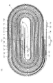
図1ないし図2A、図2B、図2Cを参照すると、本発明の一実施例による電極組立体100は、正極板110と負極板120及びセパレータ130を含む。上記正極板110と負極板120との間にはセパレータ130が介されて積層された後ゼリー−ロール(jelly−roll)形態で巻取される。
Referring to FIGS. 1 to 2A, 2B, and 2C, an
上記電極組立体100は、正極板110とセパレータ130と負極板120がゼリー−ロールタイプで巻取時に正極板110及び負極板120の両端に無地部113、123が形成される。上記無地部113、123のうちで巻取が始まる無地部を先端無地部113A、123Aと称して、巻取が終わる無地部を後端無地部113B、123Bと称する。
In the
そして、説明の便宜上巻取された正極板110及び負極板120の先端が位置する部分を電極組立体の内周部と定義して、正極板及び負極板の後端が位置する部分を電極組立体の外周部と定義する。また、無地部の両面のうちで電極組立体の内周部に向ける一側面を前面と称して、電極組立体の外周部に向ける他側面を後面と称する。前面及び後面は夫々、本発明における第1面及び第2面の一例である。
For convenience of explanation, the portion where the tips of the
したがって、上記正極無地部113で上記正極先端無地部113Aは前面に該当する第1先端正極無地部113AAと後面に該当する第2先端正極無地部113ABに区分して説明する。
Therefore, in the positive electrode
上記正極板110は、後端正極無地部113Bに正極タブ140が溶接される。そして、後端正極無地部113Bで上記正極タブ140が溶接された部位には保護テープ160を付着する。上記保護テープ160は正極集電体111に対して正極タブ140が突き出した部位を囲む状態で付着する。
In the
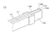
そして、上記正極板110の先端無地部113Aにはポリエチレンまたはポリプロピレンのようなラミネーションテープ170を付着する。上記先端無地部は所定長さを有して、上記ラミネーションテープは無地部の長さ程度に付着して、無地部をカバーするようになる。このように上記正極板110の先端正極無地部113Aにラミネーションテープ170を付着すると、このようなラミネーションテープ170によって先端正極無地部113Aが外部に露出しないようにする。ここで、ラミネーションテープ170とは、本発明におけるラミネーション層の一例である。また、ラミネーションテープ170は、ポリエチレン又はポリプロピレン系のラミネーション材質を有することができる。また、ラミネーションとは、例えば、プラスティック−フィルムなどのポリマーを重ねて貼り合わせることである。
Then, a
より具体的に、先端正極無地部113Aの第1先端正極無地部113AAには第1ラミネーションテープ170Aを付着して、先端正極無地部113Aの第2先端正極無地部113ABには第2ラミネーションテープ170Bを前述したように付着する。
More specifically, the
したがって、電池の内部発熱によってセパレータ130、130’の損傷や収縮が発生しても正極板110の先端正極無地部113Aの第1先端正極無地部113AAと、これに対応される負極板120の負極活物質層122Aは第1ラミネーションテープ170Aによって絶縁された状態であるので、短絡を防止するようになる。また、正極板110の先端正極無地部113Aの第2先端正極無地部113ABと、これに対応される負極板120の負極活物質層122Bは、第2ラミネーションテープ170Bによって絶縁された状態であるので、短絡を防止するようになる。
Therefore, even if the
上記正極板110は、薄板のアルミニウムホイールでなされた正極集電体111と上記正極集電体111の両面にコーティングされるリチウム系酸化物を主成分とする正極活物質層112を含んでいる。正極集電体111上には正極活物質層112がコーティングされない領域である正極無地部(positive electrode non−coating portion)113が正極板110の両末端にそれぞれ形成されて、先端無地部113Aと後端無地部113Bから構成される。
The
また、上記正極無地部113のうちいずれか一つの無地部には、正極タブ140が超音波溶接されて固定される。本発明の一実施例では上記正極板110は、後端正極無地部113Bに正極タブ140が溶接される。このように溶接される上記正極タブ140の端部は、上記正極集電体110の上端部上に突き出されるように固定される。正極タブ140は通常ニッケル、またはニッケル合金で形成されて他の金属素材も使用されることができる。
Further, the
負極板120は先、後端負極無地部123A、123Bのうち後端負極無地部123Bに負極タブ150が溶接される。そして、後端負極無地部123Bで上記負極タブ150が溶接された部位には保護テープ160を付着する。上記保護テープ160は負極集電体121に対して負極タブ150を突き出された部位を囲みながら付着する。
In the
上記負極板120は、薄板の銅ホイールでなされた負極集電体121と上記負極集電体121の両面にコーティングされた炭素材を主成分にする負極活物質層122を含んでいる。上記負極活物質層122は、負極活物質層122Aと負極活物質層122Bを含む。上記負極集電体121にも負極活物質層122がコーティングされない領域である負極無地部(negative electrode non−coating portion)123が負極板の両末端に所定領域で形成される。上記負極無地部123は、先端負極無地部123Aと後端負極無地部123Bとから構成されることは前述したところのようである。
The
上記負極無地部123の後端負極無地部123Bには負極タブ150が超音波溶接されて固定される。この時、上記負極タブ150の端部は上記負極集電体121の上端部上に突き出されるように固定される。負極タブ150は通常ニッケルまたはニッケル合金で形成されて、他の金属素材も使用されることができる。
A
上記セパレータ130は、各電極板110、120の間の絶縁のために上記正極板110と負極板120との間に配置されている。上記セパレータ130は、ポリエチレンや、ポリプロピレンや、ポリエチレンとポリプロピレンの複合フィルムでなされている。上記セパレータ130は、上記正極板110と負極板120より幅が広く形成されて、正極板110と負極板120の上、下部側に突き出されている。
The
以上で説明したところのように、本発明の一実施例による電極組立体100は、電極組立体の外周部に正極タブ140と負極タブ150を付着して、正極タブ140と負極タブ150には保護テープ160を付着する。電極組立体の内周部には正極板110の先端正極無地部113Aのうちで第1先端正極無地部113AAには第1ラミネーションテープ170Aを付着して、第2先端正極無地部113ABには第2ラミネーションテープ170Bを付着する。
As described above, the
次には、上記正極板110の先端正極無地部113Aにラミネーションテープ170;170A、170Bを付着する工程を説明する。
Next, a process of attaching the
第1、第2ラミネーションテープ170A、170Bが正極板110の第1、第2先端正極無地部113AA、113ABと同一な長さで製造されて、それぞれ第1先端正極無地部113AAと第2先端正極無地部113ABに正確に付着することが望ましい。すなわち、テープ170A、170Bが無地部113AA、113ABをすべてカバーする。
しかし、上記第1、第2ラミネーションテープ170A、170Bの長さが正極板110の第1、第2先端正極無地部113AA、113ABの長さと一致しないで第1、第2ラミネーションテープ170A、170Bのうちでいずれか一つのテープ長さが短いか、または長く製造されることもできる。
The first and
However, the lengths of the first and
または、第1、第2ラミネーションテープ170A、170Bを第1、第2先端正極無地部113AA、113ABに付着する過程で不正確な位置にテープを付着することがある。
Alternatively, the tape may be attached to an inaccurate position in the process of attaching the first and
このような製造工程上に誤差が発生されると、正極板110の第1先端正極無地部113AAまたは第2先端正極無地部113ABは、ラミネーションテープによって絶縁されない領域が発生される問題がある。
If an error is generated in such a manufacturing process, there is a problem in that the first tip positive electrode uncoated portion 113AA or the second tip positive electrode uncoated portion 113AB of the
このような製造工程上による問題が発生される場合に本発明では、ラミネーションテープを付着しなくて絶縁されない部分(概して無地部の端部で発生される)である正極板110の先端正極無地部113Aの端部を一定部分切断する。すなわち、正極無地部113Aの前、後面に第1、第2ラミネーションテープ170A、170Bを付着した状態で先端正極無地部113Aの端部を切断して、ラミネーションテープを付着しない部分を除去する。
In the case where such a problem due to the manufacturing process occurs, in the present invention, the tip positive electrode uncoated portion of the
より具体的に、先端正極無地部113Aの端部を切断する方法は、二つの方法を適用することができる。
More specifically, two methods can be applied to the method of cutting the end portion of the tip positive electrode
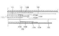
一つの切断方法は図3を参照すると、第1先端正極無地部113AAに付着した第1ラミネーションテープ170Aより第2先端正極無地部113ABに付着した第2ラミネーションテープ170Bの長さが短い状態で長さが短いラミネーションテープを基準に切断する方法である。すなわち、第2ラミネーションテープ170Bの端部Eを切断線(C)にして切断を実施する。このように相対的に長さが短い第2ラミネーションテープ170Bの端部Eを切断すると結果的に第1先端正極無地部113AAは第1ラミネーションテープ170Aによって外部と絶縁された状態になる。そして、第2先端正極無地部113ABも第2ラミネーションテープ170Bによって絶縁された状態になる。
For one cutting method, referring to FIG. 3, the length of the
したがって、正極板100の先端正極無地部113Aの前、後面は無地部の長さ程度に覆われるラミネーションテープ170;170A、170Bによって完全な絶縁状態を形成するようになる。
Accordingly, the front and rear surfaces of the positive electrode
他の一つの切断方法は図4を参照すると、第1先端正極無地部113AAに付着した第1ラミネーションテープ170Aより第2先端正極無地部113ABに付着した第2ラミネーションテープ170Bの長さが短い状態は同一である。ここで長さが短い第2ラミネーションテープ170Bの端部Eの中側に切断線C’を設定して、切断を実施するものである。このように第2ラミネーションテープ170Bの端部Eの内側に切断線C’を設定して切断を実施すると、結果的に第1先端正極無地部113AAは第1ラミネーションテープ170Aによって外部と絶縁された状態になる。そして、第2先端正極無地部113ABも第2ラミネーションテープ170Bによって絶縁された状態になる。
As for another cutting method, referring to FIG. 4, the length of the
このように長さが短い第2ラミネーションテープ170Bの内側を切断するようになると、第2ラミネーションテープ170Bの端部Eを切断する過程で発生されることができる切断誤差による不良が発生される問題を解消することができる。
When the inside of the
前述したところによる切断方式は、第2ラミネーションテープ170Bの長さが短い場合に対して説明したが、反対に第1ラミネーションテープ170Aの長さが短い場合には第1ラミネーションテープ170Aの端部を基準に切断工程を実施すると良い。
The cutting method described above has been described for the case where the length of the
このように構成された本発明の一実施例による電極組立体による内部短絡を防止する作用を説明する。 The operation of preventing the internal short circuit by the electrode assembly according to the embodiment of the present invention constructed as above will be described.
本発明の一実施例による電極組立体100の外周部には、正極タブ140と負極タブ150が設置される。
A
そして、電極組立体100の内周部には正極板110の先端正極無地部113Aにラミネーションテープ170を付着する。上記ラミネーションテープ170は第1、第2ラミネーションテープ170A、170Bでなされる。そして、第1、第2ラミネーションテープ170A、170Bが、正極板110の先端正極無地部113Aの両面に該当する第1、第2先端正極無地部113AA、113ABにそれぞれ付着される。この時、第1、第2ラミネーションテープ170A、170Bによって第1先端正極無地部113AAまたは、第2先端正極無地部113ABのうちでいずれか一つの先端無地部に絶縁状態が完全になされない場合には、必要によって正極板100の先端正極無地部113Aの端部を切断するようになる。したがって、第1、第2ラミネーションテープ170A、170Bによって第1、第2先端正極無地部113AA、113ABは外部と完全に絶縁された状態になる。
A
それで、電極組立体100の内周部で内部発熱によってセパレータ130、130’が損傷されるか、または収縮されても正極板110の先端正極無地部113Aの前、後面は隣接した負極板120の負極活物質層122A、122Bと絶縁された状態になる。それで、電極組立体100の内周部で発生される短絡を基本的に防止することができる。
Therefore, even if the
本発明の第2の実施形態に係る電極組立体を説明する。 An electrode assembly according to a second embodiment of the present invention will be described.
図5A及び図5Bを参照すると、本発明の他の実施例による電極組立体200は、正極板110と負極板120及びセパレータ130を含んで、上記正極板110と負極板120はセパレータ130が間に介されて積層された後ゼリー−ロール(jelly−roll)形態で巻取される。
Referring to FIGS. 5A and 5B, an
また、上記正極板110、負極板120及びセパレータ130と正極タブ140、負極タブ150及び保護テープ160を含む構成も本発明の一実施例と同一である。同一構成に対して同一符号を使用して詳細な説明は省略する。
The configuration including the
本発明の他の実施例による電極組立体200は、正極板の先端正極無地部113Aで第1先端正極無地部113AAのみに第1ラミネーションテープ270Aを付着する。そして、セパレータ130を間に置いて向かい合う負極板120の負極集電体121の負極活物質層122Bで上記第2先端正極無地部113ABと対応される領域に第2ラミネーションテープ270Bを付着する。
In the
このように構成された本発明の他の実施例による、電極組立体200による内部短絡を防止する作用を説明する。
The operation of preventing an internal short circuit by the
本発明の他の実施例による電極組立体200の外周部には、正極タブ140と負極タブ150が設置される。
A
そして、電極組立体200の内周部には正極板110の第1先端正極無地部113AAに第1ラミネーションテープ270Aを付着する。上記第1ラミネーションテープ270Aは、第1先端正極無地部113AAを完全に覆っていて向かい合っている負極板120の負極活物質層122Aと第1先端正極無地部113AAを絶縁させている。
The
また、第2先端正極無地部113ABが対応される負極板120の負極活物質層122Bの該当部分には、第2ラミネーションテープ270Bを付着する。
Further, the
したがって、セパレータ130、130’が損傷されるか、または収縮されても正極板110の先端正極無地部113Aのうちで第1先端正極無地部113AAは、第1ラミネーションテープ270Aによって負極活物質層122Aが絶縁される。また、正極板110の先端正極無地部113Aのうちで第2先端正極無地部113ABは、第2ラミネーションテープ270Bによって負極活物質層122Bと絶縁された状態になる。
Therefore, even if the
その結果、電極組立体200の内周部で発生される短絡を基本的に防止することができる。
As a result, it is possible to basically prevent a short circuit generated at the inner peripheral portion of the
本発明の第3の実施形態に係る電極組立体を説明する。 An electrode assembly according to a third embodiment of the present invention will be described.
図6A及び図6Bを参照すると、本発明のまた他の実施例による電極組立体300は、正極板110と負極板120及びセパレータ130を含んで、上記正極板110と負極板120はセパレータ130が間に介されて積層された後ゼリー−ロール(jelly−roll)形態で巻取される。
Referring to FIGS. 6A and 6B, an
また、上記正極板110、負極板120及びセパレータ130と正極タブ140、負極タブ150及び保護テープ160を含む構成も本発明の一実施例と同一である。同一構成に対して同一符号を使用して詳細な説明は省略する。
The configuration including the
本発明のまた他の実施例による電極組立体300は、正極板の先端正極無地部113Aの第2先端正極無地部113ABに第1ラミネーションテープ370Aを付着する。そして、セパレータ130’を間に置いて向かい合う負極板120の負極活物質層122Aには、正極板の第1先端正極無地部113AAと対応される領域に第2ラミネーションテープ370Bを付着する。
In the
このように構成された本発明のまた他の実施例による、電極組立体300による内部短絡を防止する作用を説明する。
An operation of preventing an internal short circuit by the
同実施形態に係る電極組立体300の外周部には、正極タブ140と負極タブ150が設置される。
A
そして、電極組立体300の内周部には、正極板110の第2先端正極無地部113ABに第1ラミネーションテープ370Aを付着する。上記第1ラミネーションテープ370Aは、第2先端正極無地部113ABを完全に覆っていて対応される負極板120の負極活物質層122Bと第2先端正極無地部113ABを絶縁させている。
Then, the
また、第1先端正極無地部113AAと向かい合っている負極板120の前面に形成された負極活物質層122Aには、第2ラミネーションテープ370Bを付着する。
Further, the
したがって、セパレータ130、130’が損傷されるか、または収縮されても正極板110の先端正極無地部113Aのうちで第1先端正極無地部113AAは、第2ラミネーションテープ370Bによって負極活物質層122Aと絶縁された状態が維持される。また、正極板110の先端正極無地部113Aのうちで第2先端正極無地部113ABは、第1ラミネーションテープ370Aによって負極活物質層122Bと絶縁されている。
Therefore, even if the
それで、電極組立体300の内周部で発生される短絡を基本的に防止することができる。
Therefore, a short circuit generated at the inner periphery of the
本発明は、前述したような一実施例と他の実施例及びまた他の実施例による電極組立体を利用して、リチウム二次電池に使用することができる。 The present invention can be used for a lithium secondary battery using the electrode assembly according to one embodiment, another embodiment, and another embodiment as described above.
リチウム二次電池は、ケースの種類によって角形、円筒状、パウチ型に区分されることができる。 Lithium secondary batteries can be classified into rectangular, cylindrical, and pouch types according to the type of case.
図7A及び図7Bを参照すると、パウチ型ケースを有する二次電池10が開示される。
7A and 7B, a
パウチ型リチウム二次電池10は、電極組立体100を収容することができる内部空間11を有する第1ケース12と第1ケース12の開口部を密封する第2ケース13を含む。上記第1、第2ケース12、13はアルミニウムまたはアルミニウム合金材質で形成される。
The pouch-type lithium
したがって、パウチ型二次電池10は、上記第1ケース12の内部空間11に本発明の一実施例による電極組立体100を収納して、第1ケース12と第2ケース13の縁を密封して、パウチ型二次電池の単位セルを製造するようになる。
Accordingly, the pouch-type
本発明の一実施形態に係る電極組立体100を利用したパウチ型二次電池10は、前述したところのように電極組立体100の内周部で先端正極無地部113Aの前、後面がラミネーションテープ170A、170Bによって絶縁された状態であるので、負極活物質層122と短絡が発生しなくなる。したがって、電池の内部短絡発生を著しく減らす効果があって、電池の安全性を向上させるようになる。
As described above, the pouch-type
図8を参照すると、角形ケースを有するリチウム二次電池20が開示される。
Referring to FIG. 8, a lithium
角形リチウム二次電池20は、上端部が開放されて、電極組立体100を収容することができる内部空間22を有するおおよそ直方体の缶21と、該缶21の内部に電極組立体100を収納した後上端開口部を密封しながら上記電極組立体100の電流を外部に伝達するキャップ組立体23を含む。
The prismatic lithium
したがって、本発明による角形リチウム二次電池20は、上記缶21の内部空間22に本発明の一実施形態に係る電極組立体100を収納して、缶21の上端開口部をキャップ組立体23で密封して、缶型二次電池の単位セルを製造するようになる。
Accordingly, in the prismatic lithium
本発明による角形リチウム二次電池20で上記キャップ組立体23は、電極組立体の電極端子が貫通されるキャッププレート、絶縁プレート、端子プレートなどを含む。すなわち、上記キャップ組立体23の詳細構成をより詳細に説明しなかったが、当業者の公知の技術的構成をすべて含むことは当然である。
In the prismatic lithium
このように本発明の一実施例による電極組立体100を利用した角形リチウム二次電池20は、前述したところのように電極組立体100の内周部で先端正極無地部113Aの前、後面がラミネーションテープ170A、170Bによって絶縁された状態であるので、負極活物質層122と短絡が発生されなくなる。したがって、電池の内部短絡発生を著しく減らす効果があって電池の安全性を向上させるようになる。
As described above, the prismatic lithium
図9を参照すると、円筒状ケースを有するリチウム二次電池30が開示される。
Referring to FIG. 9, a lithium
円筒状リチウム二次電池30は、上端部が開放されて電極組立体100を収容することができる内部空間32を有する円筒状缶31と、該円筒状缶31の内部に電極組立体100を収納した後、上端開口部を密封して上記電極組立体100の電流を外部に伝達するキャップ組立体33を含む。
The cylindrical lithium
したがって、本発明による円筒状リチウム二次電池30は、上記円筒状缶31の内部空間32に本発明の一実施例による電極組立体100を収納して、円筒状缶31の上端開口部をキャップ組立体33で密封して、円筒状二次電池の単位セルを製造するようになる。
Accordingly, in the cylindrical lithium
本発明による円筒状リチウム二次電池30で上記キャップ組立体33は、電極組立体の電極端子が電気的に連結されるキャップアップ、安全ベント、インシュレーター、キャップダウンなどを含む。すなわち、上記キャップ組立体33の詳細構成図をより詳細に説明しなかったが、当業者の公知の技術的構成をすべて含むことができることは当然である。
In the cylindrical lithium
このように本発明の一実施例による電極組立体100を利用した円筒状リチウム二次電池30は、前述したところのように電極組立体100の内周部で先端正極無地部113Aの前、後面がラミネーションテープ170A、170Bによって絶縁された状態であるので、負極活物質層122と短絡が発生しなくなる。したがって、電池の内部短絡発生を著しく減らす効果があって、電池の安全性を向上させるようになる。
As described above, the cylindrical lithium
一方、本発明による円筒状リチウム二次電池30では、電極組立体100の正極タブ140を電極組立体100の上部側に突き出させるようになると、負極タブ150は電極組立体100の下部側に突き出させて、円筒状缶31と電気的に連結すると良い。参照符号160は保護テープを示す。
Meanwhile, in the cylindrical lithium
以上のように、パウチ型、角形、円筒状二次電池で本発明の第1の実施形態による電極組立体100が適用された実施例を説明したが、本発明の第2の実施形態による電極組立体200及びまた第3の実施形態による電極組み立て300を適用しても同一な効果を得ることができることは当然である。
As described above, the example in which the
また、上述してきた各実施形態における正極活物質及び負極活物質がコーティングされる領域は夫々、本発明における第1のコーティング部及び第2のコーティング部の一例である。また、上述してきた各実施形態における正極及び負極は夫々、本発明における第1の電極及び第2の電極の一例である。 Moreover, the area | region where the positive electrode active material and negative electrode active material in each embodiment mentioned above are coated is an example of the 1st coating part and 2nd coating part in this invention, respectively. In addition, the positive electrode and the negative electrode in each embodiment described above are examples of the first electrode and the second electrode in the present invention, respectively.
以上、添付図面を参照しながら本発明の好適な実施形態について詳細に説明したが、本発明はかかる例に限定されない。本発明の属する技術の分野における通常の知識を有する者であれば、特許請求の範囲に記載された技術的思想の範疇内において、各種の変更例または修正例に想到し得ることは明らかであり、これらについても、当然に本発明の技術的範囲に属するものと了解される。 The preferred embodiments of the present invention have been described in detail above with reference to the accompanying drawings, but the present invention is not limited to such examples. It is obvious that a person having ordinary knowledge in the technical field to which the present invention pertains can come up with various changes or modifications within the scope of the technical idea described in the claims. Of course, it is understood that these also belong to the technical scope of the present invention.
10、20 二次電池
12、13 第1、第2ケース
21、31 缶
23、33 キャップ組立体
100 電極組立体
110 正極板
111 正極集電体
112 正極活物質層
113 正極無地部
113A 正極先端無地部
113B 正極後端無地部
113AA 第1先端正極無地部
113AB 第2先端正極無地部
120 負極板
121 負極集電体
122、122A、122B 負極活物質層
123 負極無地部
123A 負極先端無地部
123B 負極後端無地部
130 セパレータ
140 正極タブ
150 負極タブ
160 保護テープ
170 ラミネーションテープ
170A、170B 第1、第2ラミネーションテープ
10, 20
Claims (32)
前記ケースに収納されて、第1電極活物質層がコーティングされた第1コーティング部及び少なくとも一つの第1電極無地部が形成された第1電極と、
前記ケースに収納されて、第2電極活物質層がコーティングされた第2コーティング部及び少なくとも一つの第2電極無地部が形成された第2電極と、
前記第1電極と前記第2電極との間に介されるセパレータと、
前記第1電極の前記第1電極無地部に結合される第1電極タブと、
前記第2電極の前記第2電極無地部に結合される第2電極タブと、
前記第1電極無地部及び前記第2電極無地部の少なくとも一つに沿って覆うように、前記第1電極無地部及び第2電極無地部に形成される少なくとも一つのラミネーション層と、を含む、二次電池。 Case and
A first electrode housed in the case and formed with a first coating portion coated with a first electrode active material layer and at least one first electrode plain portion;
A second electrode housed in the case and formed with a second coating part coated with a second electrode active material layer and at least one second electrode plain part; and
A separator interposed between the first electrode and the second electrode;
A first electrode tab coupled to the first electrode uncoated portion of the first electrode;
A second electrode tab coupled to the second electrode plain portion of the second electrode;
Including at least one lamination layer formed on the first electrode uncoated portion and the second electrode uncoated portion so as to cover along at least one of the first electrode uncoated portion and the second electrode uncoated portion. Secondary battery.
第2電極活物質がコーティングされた第2コーティング部と先端及び後端無地部を含む第2電極と、
前記第1電極及び前記第2電極らの間に介されるセパレータと、
前記第1電極の後端無地部に結合される第1電極タブと、
前記第2電極の後端無地部に結合される第2電極タブと、
前記第1電極及び前記第2電極の無地部に前記第1電極無地部及び前記第2電極無地部の少なくとも一つに沿って覆うように形成される少なくとも一つのラミネーション層と、を含む電極組立体。 A first coating part coated with a first electrode active material, a first electrode including a front end and a rear end plain part;
A second coating part coated with a second electrode active material and a second electrode including a leading edge and a trailing edge plain part;
A separator interposed between the first electrode and the second electrode;
A first electrode tab coupled to a rear end uncoated portion of the first electrode;
A second electrode tab coupled to a rear end uncoated portion of the second electrode;
An electrode set comprising: a plain portion of the first electrode and the second electrode; and at least one lamination layer formed so as to cover along the at least one of the first electrode plain portion and the second electrode plain portion. Solid.
コーティング部と所定長さの少なくとも一つの無地部を有するために第2電極活物質を有して第2電極をコーティングする段階と、
少なくとも一つの第1、第2無地部の間にラミネーション層を配置して、少なくとも一つのラミネーション層が前記第1、第2電極の無地部の長さ程度に覆われる段階と、を含む、二次電池の製造方法。 Coating the first electrode with a first electrode active material to have a coating portion and at least one plain portion of a predetermined length;
Coating a second electrode with a second electrode active material to have a coating portion and at least one plain portion of a predetermined length;
Disposing a lamination layer between at least one of the first and second plain parts, and covering at least one of the lamination layers to a length of the plain part of the first and second electrodes. A method for manufacturing a secondary battery.
前記ラミネーション層によって覆われない前記第1電極の無地部をカッティングして、ラミネーション層を除去する段階と、
をさらに含むことを特徴とする、請求項29に記載の二次電池の製造方法。 Attaching the lamination layer to both sides of the plain portion of the first electrode;
Cutting a plain portion of the first electrode not covered by the lamination layer to remove the lamination layer;
The method for manufacturing a secondary battery according to claim 29, further comprising:
32. The method of manufacturing a secondary battery according to claim 26, wherein the coating of the second electrode is performed by coating a copper wheel with a carbon material negative electrode active material.
Applications Claiming Priority (4)
| Application Number | Priority Date | Filing Date | Title |
|---|---|---|---|
| US7456608P | 2008-06-20 | 2008-06-20 | |
| US61/074,566 | 2008-06-20 | ||
| US12/356,332 | 2009-01-20 | ||
| US12/356,332 US8628876B2 (en) | 2008-06-20 | 2009-01-20 | Electrode assembly and lithium secondary battery with same |
Publications (2)
| Publication Number | Publication Date |
|---|---|
| JP2010003692A true JP2010003692A (en) | 2010-01-07 |
| JP5214543B2 JP5214543B2 (en) | 2013-06-19 |
Family
ID=41112164
Family Applications (1)
| Application Number | Title | Priority Date | Filing Date |
|---|---|---|---|
| JP2009145627A Active JP5214543B2 (en) | 2008-06-20 | 2009-06-18 | Secondary battery |
Country Status (4)
| Country | Link |
|---|---|
| US (1) | US8628876B2 (en) |
| EP (1) | EP2136429B1 (en) |
| JP (1) | JP5214543B2 (en) |
| KR (1) | KR101182904B1 (en) |
Cited By (2)
| Publication number | Priority date | Publication date | Assignee | Title |
|---|---|---|---|---|
| JP2012079696A (en) * | 2010-10-01 | 2012-04-19 | Samsung Sdi Co Ltd | Secondary battery |
| WO2012164642A1 (en) * | 2011-05-27 | 2012-12-06 | トヨタ自動車株式会社 | Bipolar all-solid-state battery |
Families Citing this family (28)
| Publication number | Priority date | Publication date | Assignee | Title |
|---|---|---|---|---|
| KR101025277B1 (en) | 2007-10-30 | 2011-03-29 | 삼성에스디아이 주식회사 | Electrode assembly and secondary battery using the same |
| KR101106377B1 (en) * | 2009-07-16 | 2012-01-18 | 삼성에스디아이 주식회사 | Rechargeable Battery |
| US8815437B2 (en) * | 2009-09-10 | 2014-08-26 | Samsung Sdi Co., Ltd. | Rechargeable battery |
| US8889286B2 (en) * | 2009-10-01 | 2014-11-18 | Samsung Sdi Co., Ltd. | Secondary battery and method of fabricating secondary battery |
| US8546007B2 (en) * | 2009-10-29 | 2013-10-01 | Samsung Sdi Co., Ltd. | Rechargeable battery |
| JP5676620B2 (en) * | 2010-08-23 | 2015-02-25 | エルジー・ケム・リミテッド | Improved structure jelly roll and secondary battery including the same |
| CN103299453A (en) * | 2011-01-25 | 2013-09-11 | 株式会社Lg化学 | Cylindrical secondary battery |
| JP5935265B2 (en) * | 2011-08-29 | 2016-06-15 | Tdk株式会社 | Winding electrochemical device |
| KR101987335B1 (en) * | 2012-01-20 | 2019-06-10 | 에스케이이노베이션 주식회사 | Electrode assembly for Secondary Battery |
| JP6106913B2 (en) * | 2013-06-28 | 2017-04-05 | エルジー・ケム・リミテッド | Method for manufacturing electrode assembly including separator cutting step |
| KR101629498B1 (en) * | 2013-10-08 | 2016-06-10 | 주식회사 엘지화학 | Electrode assembly and secondary battery comprising the same |
| KR101629499B1 (en) * | 2013-10-14 | 2016-06-10 | 주식회사 엘지화학 | Electrode assembly and secondary battery comprising the same |
| US20160260978A1 (en) * | 2013-10-30 | 2016-09-08 | Nissan Motor Co., Ltd. | Electrode and Battery Including Electrode |
| KR102235279B1 (en) * | 2014-10-31 | 2021-04-01 | 삼성에스디아이 주식회사 | Rechargeable battery |
| KR102279223B1 (en) * | 2014-11-25 | 2021-07-19 | 삼성에스디아이 주식회사 | Electrode assembly having protection tape and rechargeable battery having thereof |
| KR102361705B1 (en) * | 2015-03-03 | 2022-02-10 | 삼성에스디아이 주식회사 | Rechargeable battery having cover |
| KR102277352B1 (en) * | 2016-08-24 | 2021-07-14 | 삼성에스디아이 주식회사 | Electrode assembly and rechargeable battery including the same |
| KR102256297B1 (en) * | 2016-09-07 | 2021-05-26 | 삼성에스디아이 주식회사 | secondary battery |
| KR20180028837A (en) * | 2016-09-09 | 2018-03-19 | 삼성에스디아이 주식회사 | Rechargeable battery |
| KR102152143B1 (en) * | 2016-11-24 | 2020-09-04 | 주식회사 엘지화학 | Electrode Assembly Comprising Separator Having Insulation-enhancing Part Formed on Edge Portion of Electrode |
| CN106654348B (en) * | 2017-02-20 | 2023-05-30 | 南通耐维特电源有限公司 | Lithium battery |
| KR20180097085A (en) | 2017-02-22 | 2018-08-30 | 삼성에스디아이 주식회사 | Secondary battery having a structure capable of suppressing short circuit of multi-tap |
| KR20190098560A (en) | 2018-02-14 | 2019-08-22 | 삼성에스디아이 주식회사 | Electrode assembly and secondary battery comprising the same |
| KR20220016554A (en) * | 2020-08-03 | 2022-02-10 | 주식회사 엘지에너지솔루션 | Electrode assembly including disconnection preventing layer and method for manufacturing the same |
| KR20220067279A (en) * | 2020-11-17 | 2022-05-24 | 주식회사 엘지에너지솔루션 | Insulation evaluation method of overlay electrode |
| KR20220092314A (en) * | 2020-12-24 | 2022-07-01 | 주식회사 엘지에너지솔루션 | Electrode assembly and rechargeable battery comprising the same |
| SE545601C2 (en) * | 2021-08-19 | 2023-11-07 | Northvolt Ab | Cylindrical battery cell with notches |
| CN217468544U (en) * | 2022-06-10 | 2022-09-20 | 珠海冠宇电池股份有限公司 | Winding battery and electronic equipment |
Citations (5)
| Publication number | Priority date | Publication date | Assignee | Title |
|---|---|---|---|---|
| JP2001093583A (en) * | 1998-11-16 | 2001-04-06 | Denso Corp | Stacked battery and fabricating method thereof |
| JP2005222884A (en) * | 2004-02-09 | 2005-08-18 | Sony Corp | Electrode lamination type battery |
| JP2005347161A (en) * | 2004-06-04 | 2005-12-15 | Sony Corp | Battery |
| JP2006024452A (en) * | 2004-07-08 | 2006-01-26 | Matsushita Electric Ind Co Ltd | Organic electrolyte primary battery |
| JP2006120604A (en) * | 2004-09-03 | 2006-05-11 | Matsushita Electric Ind Co Ltd | Lithium ion secondary battery |
Family Cites Families (14)
| Publication number | Priority date | Publication date | Assignee | Title |
|---|---|---|---|---|
| JPH10184939A (en) | 1996-12-24 | 1998-07-14 | Daiadeitsuku Syst:Kk | Flow control servo valve |
| KR100344686B1 (en) | 1997-02-28 | 2002-07-25 | 아사히 가세이 가부시키가이샤 | Nonaqueous Secondary Battery and Method for Manufacturing the Same |
| JP3831525B2 (en) | 1998-06-30 | 2006-10-11 | 三洋電機株式会社 | battery |
| JP4265014B2 (en) | 1998-12-22 | 2009-05-20 | ソニー株式会社 | Thin battery |
| KR100449757B1 (en) * | 2001-11-23 | 2004-09-22 | 삼성에스디아이 주식회사 | Battery unit and secondary battery applying the such |
| US7335448B2 (en) * | 2002-05-30 | 2008-02-26 | Matsushita Electric Industrial Co., Ltd. | Lithium ion secondary battery |
| JP4382557B2 (en) | 2004-03-30 | 2009-12-16 | 日立マクセル株式会社 | Non-aqueous secondary battery |
| KR100591436B1 (en) | 2004-03-30 | 2006-06-22 | 삼성에스디아이 주식회사 | Secondary battery can prevent internal short circuit |
| JP4878800B2 (en) * | 2004-09-22 | 2012-02-15 | 三星エスディアイ株式会社 | Lithium secondary battery |
| KR100686851B1 (en) | 2005-05-30 | 2007-02-26 | 삼성에스디아이 주식회사 | Composite Material Tape for Lithium Secondary battery and Lithium Secondary battery using the Same |
| KR100561303B1 (en) | 2004-09-22 | 2006-03-15 | 삼성에스디아이 주식회사 | Pouch type lithium secondary battery |
| KR20070087857A (en) | 2005-12-29 | 2007-08-29 | 삼성에스디아이 주식회사 | Lithium rechargeable battery |
| JP5002965B2 (en) | 2006-01-20 | 2012-08-15 | ソニー株式会社 | Non-aqueous electrolyte battery and manufacturing apparatus thereof |
| JP4586820B2 (en) * | 2007-05-07 | 2010-11-24 | ソニー株式会社 | Winding type non-aqueous electrolyte secondary battery |
-
2009
- 2009-01-20 US US12/356,332 patent/US8628876B2/en active Active
- 2009-05-27 KR KR1020090046638A patent/KR101182904B1/en active IP Right Grant
- 2009-06-18 JP JP2009145627A patent/JP5214543B2/en active Active
- 2009-06-19 EP EP09251605.3A patent/EP2136429B1/en active Active
Patent Citations (5)
| Publication number | Priority date | Publication date | Assignee | Title |
|---|---|---|---|---|
| JP2001093583A (en) * | 1998-11-16 | 2001-04-06 | Denso Corp | Stacked battery and fabricating method thereof |
| JP2005222884A (en) * | 2004-02-09 | 2005-08-18 | Sony Corp | Electrode lamination type battery |
| JP2005347161A (en) * | 2004-06-04 | 2005-12-15 | Sony Corp | Battery |
| JP2006024452A (en) * | 2004-07-08 | 2006-01-26 | Matsushita Electric Ind Co Ltd | Organic electrolyte primary battery |
| JP2006120604A (en) * | 2004-09-03 | 2006-05-11 | Matsushita Electric Ind Co Ltd | Lithium ion secondary battery |
Cited By (6)
| Publication number | Priority date | Publication date | Assignee | Title |
|---|---|---|---|---|
| JP2012079696A (en) * | 2010-10-01 | 2012-04-19 | Samsung Sdi Co Ltd | Secondary battery |
| US9490464B2 (en) | 2010-10-01 | 2016-11-08 | Samsung Sdi Co., Ltd. | Secondary battery |
| WO2012164642A1 (en) * | 2011-05-27 | 2012-12-06 | トヨタ自動車株式会社 | Bipolar all-solid-state battery |
| CN103548196A (en) * | 2011-05-27 | 2014-01-29 | 丰田自动车株式会社 | Bipolar all-solid-state battery |
| JP5720779B2 (en) * | 2011-05-27 | 2015-05-20 | トヨタ自動車株式会社 | Bipolar all-solid battery |
| KR101577881B1 (en) * | 2011-05-27 | 2015-12-15 | 도요타 지도샤(주) | Bipolar all-solid-state battery |
Also Published As
| Publication number | Publication date |
|---|---|
| EP2136429A1 (en) | 2009-12-23 |
| KR20090132500A (en) | 2009-12-30 |
| US20090317713A1 (en) | 2009-12-24 |
| KR101182904B1 (en) | 2012-09-13 |
| EP2136429B1 (en) | 2018-08-01 |
| JP5214543B2 (en) | 2013-06-19 |
| US8628876B2 (en) | 2014-01-14 |
Similar Documents
| Publication | Publication Date | Title |
|---|---|---|
| JP5214543B2 (en) | Secondary battery | |
| KR101106377B1 (en) | Rechargeable Battery | |
| JP6735445B2 (en) | Wound battery | |
| KR101136156B1 (en) | Secondary battery and method of making the secondary battery | |
| JP6505859B2 (en) | Nonaqueous electrolyte secondary battery | |
| JP5174840B2 (en) | Secondary battery | |
| JP3972205B2 (en) | Stacked battery | |
| KR100515833B1 (en) | Jelly-roll type electrode assembly and secondary battery applying the same | |
| JP2006252802A (en) | Tab lead for nonaqueous electrolyte battery and nonaqueous electrolyte battery | |
| JPWO2017010046A1 (en) | Winding battery | |
| KR20140094205A (en) | Rechargeable battery | |
| US20220352606A1 (en) | Secondary battery and method for manufacturing same | |
| JP6775170B2 (en) | Revolving battery | |
| KR20160134331A (en) | Pouch type secondary battery and method for fabricating the same | |
| US20190363329A1 (en) | Secondary battery | |
| US20190363331A1 (en) | Secondary battery | |
| KR20190037110A (en) | Electrochemical device | |
| JP2018055904A (en) | Electrochemical cell and manufacturing method of the electrochemical cell | |
| JP2017162761A (en) | Electrochemical cell and manufacturing method of electrochemical cell | |
| JP2020057485A (en) | Laminate-type secondary battery and method for producing the same | |
| JP7317877B2 (en) | Non-aqueous electrolyte secondary battery | |
| WO2022196460A1 (en) | Electrochemical cell | |
| JP2022123651A (en) | Power-storage cell and power storage device | |
| JP2023084066A (en) | secondary battery | |
| JP6213068B2 (en) | Electrochemical element |
Legal Events
| Date | Code | Title | Description |
|---|---|---|---|
| A131 | Notification of reasons for refusal |
Free format text: JAPANESE INTERMEDIATE CODE: A131 Effective date: 20120710 |
|
| A521 | Request for written amendment filed |
Free format text: JAPANESE INTERMEDIATE CODE: A523 Effective date: 20121003 |
|
| RD03 | Notification of appointment of power of attorney |
Free format text: JAPANESE INTERMEDIATE CODE: A7423 Effective date: 20121003 |
|
| A131 | Notification of reasons for refusal |
Free format text: JAPANESE INTERMEDIATE CODE: A131 Effective date: 20121030 |
|
| A521 | Request for written amendment filed |
Free format text: JAPANESE INTERMEDIATE CODE: A523 Effective date: 20130128 |
|
| TRDD | Decision of grant or rejection written | ||
| A01 | Written decision to grant a patent or to grant a registration (utility model) |
Free format text: JAPANESE INTERMEDIATE CODE: A01 Effective date: 20130219 |
|
| A61 | First payment of annual fees (during grant procedure) |
Free format text: JAPANESE INTERMEDIATE CODE: A61 Effective date: 20130227 |
|
| R150 | Certificate of patent or registration of utility model |
Ref document number: 5214543 Country of ref document: JP Free format text: JAPANESE INTERMEDIATE CODE: R150 Free format text: JAPANESE INTERMEDIATE CODE: R150 |
|
| FPAY | Renewal fee payment (event date is renewal date of database) |
Free format text: PAYMENT UNTIL: 20160308 Year of fee payment: 3 |
|
| R250 | Receipt of annual fees |
Free format text: JAPANESE INTERMEDIATE CODE: R250 |
|
| R250 | Receipt of annual fees |
Free format text: JAPANESE INTERMEDIATE CODE: R250 |
|
| R250 | Receipt of annual fees |
Free format text: JAPANESE INTERMEDIATE CODE: R250 |
|
| R250 | Receipt of annual fees |
Free format text: JAPANESE INTERMEDIATE CODE: R250 |
|
| R250 | Receipt of annual fees |
Free format text: JAPANESE INTERMEDIATE CODE: R250 |
|
| R250 | Receipt of annual fees |
Free format text: JAPANESE INTERMEDIATE CODE: R250 |
|
| R250 | Receipt of annual fees |
Free format text: JAPANESE INTERMEDIATE CODE: R250 |
|
| R250 | Receipt of annual fees |
Free format text: JAPANESE INTERMEDIATE CODE: R250 |
|
| R250 | Receipt of annual fees |
Free format text: JAPANESE INTERMEDIATE CODE: R250 |