JP2010003232A - Eye detection device - Google Patents
Eye detection device Download PDFInfo
- Publication number
- JP2010003232A JP2010003232A JP2008163452A JP2008163452A JP2010003232A JP 2010003232 A JP2010003232 A JP 2010003232A JP 2008163452 A JP2008163452 A JP 2008163452A JP 2008163452 A JP2008163452 A JP 2008163452A JP 2010003232 A JP2010003232 A JP 2010003232A
- Authority
- JP
- Japan
- Prior art keywords
- face
- contour
- eye
- driver
- edge
- Prior art date
- Legal status (The legal status is an assumption and is not a legal conclusion. Google has not performed a legal analysis and makes no representation as to the accuracy of the status listed.)
- Granted
Links
- 238000001514 detection method Methods 0.000 title claims abstract description 26
- 210000000744 eyelid Anatomy 0.000 abstract description 27
- 239000000284 extract Substances 0.000 abstract description 3
- 239000011521 glass Substances 0.000 description 10
- 238000000034 method Methods 0.000 description 8
- 238000000605 extraction Methods 0.000 description 5
- 125000002066 L-histidyl group Chemical group [H]N1C([H])=NC(C([H])([H])[C@](C(=O)[*])([H])N([H])[H])=C1[H] 0.000 description 3
- 208000001491 myopia Diseases 0.000 description 3
- 238000010586 diagram Methods 0.000 description 2
- 230000004379 myopia Effects 0.000 description 2
- 230000037303 wrinkles Effects 0.000 description 2
- 206010020675 Hypermetropia Diseases 0.000 description 1
- 238000012790 confirmation Methods 0.000 description 1
- 210000000887 face Anatomy 0.000 description 1
- 201000006318 hyperopia Diseases 0.000 description 1
- 230000004305 hyperopia Effects 0.000 description 1
- 238000012567 pattern recognition method Methods 0.000 description 1
- 201000010041 presbyopia Diseases 0.000 description 1
Images

Abstract
Description
本発明は、例えば車両の運転者等の眼を検出する眼検出装置に関するものである。 The present invention relates to an eye detection device that detects eyes of a driver of a vehicle, for example.
従来の眼検出装置としては、例えば特許文献1に記載されているように、運転者の顔を撮像し、運転者の眼画像からエッジ抽出により上瞼の曲率を検出し、この上瞼の曲率に基づいて開閉眼の判定を行うようにしたものが知られている。
しかしながら、上記従来技術においては、運転者が眼鏡を着用している場合に、眼鏡のエッジを眼の瞼のエッジと誤って検出し、結果的に運転者の開閉眼を誤判定してしまう虞がある。 However, in the above prior art, when the driver is wearing glasses, the edge of the glasses is erroneously detected as the edge of the eyelid, and as a result, the driver's opening / closing eye may be erroneously determined. There is.
本発明の目的は、眼鏡を着用した対象者の顔画像において眼鏡の輪郭と眼の輪郭との誤検出を防止することができる眼検出装置を提供することである。 The objective of this invention is providing the eye detection apparatus which can prevent the misdetection with the outline of glasses and the outline of eyes in the face image of the subject who wears glasses.
本発明は、対象者の顔画像を取得し、当該顔画像に基づいて対象者の眼を検出する眼検出装置において、顔画像における対象者の眼輪郭候補を抽出する眼輪郭候補抽出手段と、顔画像における対象者の顔輪郭を抽出する顔輪郭抽出手段と、顔画像における対象者の顔が横を向いているかどうかを検出する顔向き検出手段と、顔向き検出手段により対象者の顔が横を向いていることが検出されたときに、眼輪郭候補の上下で顔輪郭が非連続となっているかどうかを判断する判断手段と、判断手段により眼輪郭候補の上下で顔輪郭が非連続となっていると判断されたときは、当該眼輪郭候補を対象者の眼輪郭でないと判定する判別手段とを備えることを特徴とするものである。 The present invention provides an eye contour candidate extraction unit that extracts a target person's eye contour candidate in a face image in an eye detection device that acquires the target person's face image and detects the subject's eye based on the face image. The face contour extracting means for extracting the face contour of the subject in the face image, the face direction detecting means for detecting whether the face of the subject in the face image is facing sideways, and the face orientation detecting means A determination means for determining whether or not the face contour is discontinuous above and below the eye contour candidate when it is detected facing sideways; and the face contour is discontinuous above and below the eye contour candidate by the determination means And determining means for determining that the eye contour candidate is not the eye contour of the subject person.
本発明は、眼鏡を着用した対象者が横(左右)に顔を向けると、眼鏡のレンズ内で顔の輪郭がずれるという現象に着目して成されたものである。即ち、本発明の眼検出装置においては、対象者の顔画像に基づいて、対象者の眼輪郭候補及び顔輪郭を抽出すると共に、対象者の顔が横を向いているかどうかを検出する。そして、対象者の顔が横を向いているときは、眼輪郭候補の上下で顔輪郭が非連続となっているかどうかを判断する。この際に、眼輪郭候補の上下で顔輪郭がずれて非連続となっているときは、その眼輪郭候補は対象者の眼の輪郭ではなく、対象者が着用している眼鏡の輪郭であると判定する。これにより、眼鏡の輪郭を眼の輪郭と誤検出してしまうことが防止される。 The present invention is made by paying attention to a phenomenon in which the outline of a face shifts in the lens of the eyeglass when the subject wearing the eyeglasses turns his face sideways (left and right). That is, in the eye detection device of the present invention, the candidate's eye contour candidate and face contour are extracted based on the subject's face image, and whether the subject's face is facing sideways is detected. When the subject's face is facing sideways, it is determined whether the face contour is discontinuous above and below the eye contour candidate. At this time, when the face contour is shifted and discontinuous above and below the eye contour candidate, the eye contour candidate is not the eye contour of the subject but the contour of the glasses worn by the subject. Is determined. This prevents erroneous detection of the eyeglass contour as the eye contour.
好ましくは、判断手段は、眼輪郭候補を延長させた仮想ラインの上下で顔輪郭にずれがあるか否かによって、眼輪郭候補の上下で顔輪郭が非連続となっているかどうかを判断する。この場合には、対象者の顔向き角度によっては眼輪郭候補が顔輪郭に交わらない状態となっても、眼輪郭候補を延長させた仮想ラインが顔輪郭に交わるようになるため、眼輪郭候補の上下で顔輪郭がずれて非連続となっているかどうかを正確に判断することができる。 Preferably, the determination unit determines whether or not the face contour is discontinuous above and below the eye contour candidate based on whether or not the face contour is shifted above and below the virtual line obtained by extending the eye contour candidate. In this case, even if the eye contour candidate does not intersect the face contour depending on the face orientation angle of the target person, the virtual line obtained by extending the eye contour candidate intersects the face contour. It is possible to accurately determine whether or not the face contour is shifted up and down and is discontinuous.
本発明によれば、眼鏡を着用した対象者の顔画像において眼鏡の輪郭と眼の輪郭との誤検出を防止することができる。これにより、対象者の顔の特徴点である眼を正確に検出することが可能となる。 ADVANTAGE OF THE INVENTION According to this invention, the misdetection with the outline of spectacles and the outline of eyes can be prevented in the face image of the subject wearing spectacles. This makes it possible to accurately detect the eyes that are feature points of the subject's face.
以下、本発明に係わる眼検出装置の好適な実施形態について、図面を参照して詳細に説明する。 DESCRIPTION OF EMBODIMENTS Hereinafter, preferred embodiments of an eye detection device according to the present invention will be described in detail with reference to the drawings.
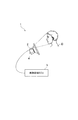
図1は、本発明に係わる眼検出装置の一実施形態を示す概略構成図である。同図において、本実施形態の眼検出装置1は、車両に搭載され、運転者Dの眼を検出する装置である。眼検出装置1は、画像センサ2と、この画像センサ2と接続された画像処理ECU(Electronic Control Unit)3とを備えている。
FIG. 1 is a schematic configuration diagram showing an embodiment of an eye detection apparatus according to the present invention. In the figure, an
画像センサ2は、例えばステアリングコラムカバー4上に設置され、運転者Dの顔を撮像して運転者Dの顔画像を取得するセンサである。画像センサ2としては、例えばCCDカメラが用いられる。
The
画像処理ECU3は、CPU、ROM、RAM等からなるマイクロコンピュータを主要構成部品としている。画像処理ECU3は、画像センサ2で取得された運転者Dの顔画像を入力し、画像処理を含む所定の処理を行い、運転者Dの上下瞼(まぶた)を検出する。画像処理ECU3は、1つの画像センサ2で取得された画像のみを処理するので、複数の画像を処理する場合のような非常に高速な処理チップが不要となる。
The
図2は、画像処理ECU3により実行される瞼検出処理手順の詳細を示すフローチャートである。同図において、まず画像センサ2により得られた運転者Dの顔画像データを入力する(手順S51)。
FIG. 2 is a flowchart showing details of the wrinkle detection processing procedure executed by the
そして、例えばエッジベース手法やパターン認識手法等を使って、運転者Dの顔画像データ上における運転者Dの複数の上下瞼候補エッジ(図4のP1〜P4参照)を抽出する(手順S52)。このとき、例えばエッジ強度やエッジの連続性をパラメータとして尤度を求め、この尤度が所定値よりも高いものを上下瞼候補エッジとして抽出する。 Then, for example, a plurality of upper and lower eyelid candidate edges (see P 1 to P 4 in FIG. 4) of the driver D on the face image data of the driver D are extracted by using an edge-based method or a pattern recognition method (procedure) S52). At this time, for example, the likelihood is obtained by using the edge strength and the continuity of the edge as parameters, and those having a likelihood higher than a predetermined value are extracted as upper and lower eyelid candidate edges.
続いて、運転者Dの顔画像データ上における運転者Dの横方向(左右方向)の顔向き角度を検出する(手順S53)。このとき、画像処理によって、顔向きのロール角度(回転角度)、ピッチ角度(上下方向の角度)及びヨー角度(左右方向の角度)を算出する。 Subsequently, the face direction angle of the driver D in the lateral direction (left and right direction) on the face image data of the driver D is detected (step S53). At this time, a roll angle (rotation angle), a pitch angle (vertical angle), and a yaw angle (horizontal angle) are calculated by image processing.
そして、運転者Dの顔が正面方向を向かずに横方向を向いているかどうかを判断する(手順S54)。具体的には、運転者Dの顔向きのヨー角度が予め設定された閾値を越えたかどうかを判断する。運転者Dの顔が正面方向を向いていると判断されたときは、手順S52に戻る。 Then, it is determined whether or not the face of the driver D faces in the lateral direction without facing the front direction (step S54). Specifically, it is determined whether or not the yaw angle of the driver D's face exceeds a preset threshold value. When it is determined that the face of the driver D is facing the front, the process returns to step S52.
一方、運転者Dの顔が横方向を向いていると判断されたときは、運転者Dの顔画像データ上における顔輪郭エッジ(図4のQ参照)を抽出する(手順S55)。そして、上記手順S52で抽出された各上下瞼候補エッジの上下で顔輪郭エッジの段差が無いかどうかを判断する(手順S56)。 On the other hand, when it is determined that the face of the driver D is facing sideways, a face contour edge (see Q in FIG. 4) on the face image data of the driver D is extracted (step S55). Then, it is determined whether or not there is a step of the face contour edge above and below each of the upper and lower eyelid candidate edges extracted in step S52 (step S56).
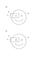
ここで、運転者Dが眼鏡を着用している場合には、運転者Dが左右の確認等のために左右方向(横方向)に顔を向けると、眼鏡のレンズを通した時に見える顔の輪郭線がずれるという現象が発生する。具体的には、眼鏡のレンズが近眼(近視)用レンズの場合には、運転者Dが左右方向に顔を向けると、図3(a)に示すように、眼鏡Gのレンズ内で顔の輪郭線hが内側へずれるようになり、眼鏡のレンズが老眼(遠視)用レンズの場合には、運転者Dが左右方向に顔を向けると、図3(b)に示すように、眼鏡Gのレンズ内で顔の輪郭線hが外側へずれるようになる。 Here, when the driver D wears glasses, when the driver D turns his / her face in the left / right direction (lateral direction) for left / right confirmation or the like, the face seen through the lens of the glasses is displayed. The phenomenon that the contour line shifts occurs. Specifically, when the spectacle lens is a near-sighted (myopia) lens, when the driver D turns his face in the left-right direction, as shown in FIG. When the contour line h shifts inward and the spectacle lens is a presbyopia (hyperopia) lens, when the driver D turns his face in the left-right direction, as shown in FIG. The contour line h of the face is shifted outward in the lens.
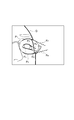
そこで、図4に示すように、上下瞼候補エッジP1〜P4をそれぞれ顔の外側に延長させた仮想ラインR1〜R4(破線参照)を引く。このとき、顔輪郭エッジQに一番近い画素座標(例えば5点)から仮想ラインR1〜R4を引くようにする。これにより、運転者Dの顔向きのヨー角度によっては真の上下瞼エッジに相当する上下瞼候補エッジP1,P2が顔輪郭エッジQと交わらない場合でも、当該上下瞼候補エッジP1,P2を延長させた仮想ラインR1,R2が顔輪郭エッジQと交わるようになる。なお、図4は、近眼用の眼鏡を着用した運転者Dが左右方向に顔を向けた時の顔画像を示したものである。
Therefore, as shown in FIG. 4, virtual lines R 1 to R 4 (see broken lines) obtained by extending the upper and lower eyelid candidate edges P 1 to P 4 to the outside of the face are drawn. At this time, virtual lines R 1 to R 4 are drawn from pixel coordinates (for example, five points) closest to the face contour edge Q. Thus, depending on the yaw angle of the face of the driver D, even if the upper and lower eyelid candidate edges P 1 and P 2 corresponding to the true upper and lower eyelid edges do not intersect the face contour edge Q, the upper and lower eyelid candidate edges P 1 and
そして、上下瞼候補エッジP1〜P4を延長させた仮想ラインR1〜R4の上下で顔輪郭エッジQにずれ(段差)が無いかどうかを判断する。 Then, it is determined whether the upper and lower vertical eyelid edge P 1 to P 4 virtual line R 1 to R 4 which is extended shift the face contour edge Q (step) is not.
上下瞼候補エッジを延長させた仮想ラインの上下で顔輪郭エッジにずれが無い(図4中のR2,R3参照)ときは、その上下瞼候補エッジを上下瞼のエッジと断定する(手順S57)。一方、上下瞼候補エッジを延長させた仮想ラインの上下で顔輪郭エッジにずれがある(図4中のR1,R4参照)ときは、その上下瞼候補エッジを眼鏡のエッジと断定し、上下瞼候補エッジから除外する(手順S58)。 If the face contour edge is not shifted above and below the virtual line obtained by extending the upper and lower eyelid candidate edges (see R 2 and R 3 in FIG. 4), the upper and lower eyelid candidate edges are determined to be the upper and lower eyelid edges (procedure) S57). On the other hand, when the face contour edge is shifted above and below the virtual line obtained by extending the upper / lower eyelid candidate edge (see R 1 and R 4 in FIG. 4), the upper / lower eyelid candidate edge is determined as the eyeglass edge, Exclude from the upper and lower eyelid candidate edges (step S58).
以上において、手順S51,S52は、顔画像における対象者の眼輪郭候補を抽出する眼輪郭候補抽出手段を構成する。手順S51,S55は、顔画像における対象者の顔輪郭を抽出する顔輪郭抽出手段を構成する。手順S51,S53,S54は、顔画像における対象者の顔が横を向いているかどうかを検出する顔向き検出手段を構成する。手順S56は、顔向き検出手段により対象者の顔が横を向いていることが検出されたときに、眼輪郭候補の上下で顔輪郭が非連続となっているかどうかを判断する判断手段を構成する。手順S58は、判断手段により眼輪郭候補の上下で顔輪郭が非連続となっていると判断されたときは、当該眼輪郭候補を対象者の眼輪郭でないと判定する判別手段を構成する。 In the above, steps S51 and S52 constitute eye contour candidate extraction means for extracting the subject's eye contour candidate from the face image. Steps S51 and S55 constitute face contour extracting means for extracting the face contour of the subject in the face image. Steps S51, S53, and S54 constitute face orientation detection means for detecting whether the face of the subject in the face image is facing sideways. Step S56 constitutes determination means for determining whether or not the face contour is discontinuous above and below the eye contour candidate when the face orientation detection means detects that the subject's face is facing sideways. To do. Step S58 constitutes a determining unit that determines that the eye contour candidate is not the eye contour of the subject when the determining unit determines that the face contour is discontinuous above and below the eye contour candidate.
以上のように本実施形態にあっては、運転者Dの顔画像データに基づいて、運転者Dの上下瞼候補エッジを抽出すると共に運転者Dの横方向の顔向き角度を検出し、顔が正面方向を向いていないときは、更に顔画像データに基づいて顔輪郭エッジを抽出する。そして、各上下瞼候補エッジを延長させた仮想ラインの上下における顔輪郭エッジの連続性を判断し、仮想ラインの上下で顔輪郭エッジが非連続であると判断されたときは、当該上下瞼候補エッジを眼鏡のエッジと断定し、眼の輪郭エッジとして抽出しないようにする。これにより、運転者Dが眼鏡を着用している場合に、運転者Dの顔画像において眼鏡のエッジを眼の輪郭エッジとして誤検出することを防止できるようになる。 As described above, in the present embodiment, the upper and lower eyelid candidate edges of the driver D are extracted on the basis of the face image data of the driver D, and the lateral direction angle of the driver D is detected, When is not facing the front direction, a face contour edge is further extracted based on the face image data. Then, the continuity of the face contour edge above and below the virtual line obtained by extending each of the upper and lower eyelid candidate edges is determined, and when it is determined that the face contour edge is not continuous above and below the virtual line, the upper and lower eyelid candidate The edge is determined to be an eyeglass edge so that it is not extracted as an eye contour edge. Accordingly, when the driver D is wearing glasses, it is possible to prevent erroneous detection of the edge of the glasses as the eye contour edge in the face image of the driver D.
なお、本発明は、上記実施形態に限定されるものではない。例えば上記実施形態の眼検出装置1は、車両の運転者Dの眼を検出するものであるが、本発明は、特に車両用には限られず、例えばロボットに搭載して、ロボット周囲の人物の眼を検出するもの等にも適用可能である。
The present invention is not limited to the above embodiment. For example, the
1…眼検出装置、2…画像センサ、3…画像処理ECU(眼輪郭候補抽出手段、顔輪郭抽出手段、顔向き検出手段、判断手段、判別手段)、D…運転者(対象者)。
DESCRIPTION OF
Claims (2)
前記顔画像における前記対象者の眼輪郭候補を抽出する眼輪郭候補抽出手段と、
前記顔画像における前記対象者の顔輪郭を抽出する顔輪郭抽出手段と、
前記顔画像における前記対象者の顔が横を向いているかどうかを検出する顔向き検出手段と、
前記顔向き検出手段により前記対象者の顔が横を向いていることが検出されたときに、前記眼輪郭候補の上下で前記顔輪郭が非連続となっているかどうかを判断する判断手段と、
前記判断手段により前記眼輪郭候補の上下で前記顔輪郭が非連続となっていると判断されたときは、当該眼輪郭候補を前記対象者の眼輪郭でないと判定する判別手段とを備えることを特徴とする眼検出装置。 In an eye detection device that acquires a face image of a subject and detects the eyes of the subject based on the face image.
Eye contour candidate extracting means for extracting eye contour candidates of the subject in the face image;
A face contour extracting means for extracting the face contour of the subject in the face image;
Face orientation detection means for detecting whether the face of the subject in the face image is facing sideways;
Determining means for determining whether the face contour is discontinuous above and below the eye contour candidate when the face orientation detecting means detects that the subject's face is facing sideways;
And determining means for determining that the eye contour candidate is not the eye contour of the subject when the determining means determines that the face contour is discontinuous above and below the eye contour candidate. A featured eye detection device.
The determination unit determines whether the face contour is discontinuous above and below the eye contour candidate, depending on whether the face contour is shifted above and below a virtual line obtained by extending the eye contour candidate. The eye detection device according to claim 1.
Priority Applications (1)
| Application Number | Priority Date | Filing Date | Title |
|---|---|---|---|
| JP2008163452A JP4978574B2 (en) | 2008-06-23 | 2008-06-23 | Eye detection device |
Applications Claiming Priority (1)
| Application Number | Priority Date | Filing Date | Title |
|---|---|---|---|
| JP2008163452A JP4978574B2 (en) | 2008-06-23 | 2008-06-23 | Eye detection device |
Publications (2)
| Publication Number | Publication Date |
|---|---|
| JP2010003232A true JP2010003232A (en) | 2010-01-07 |
| JP4978574B2 JP4978574B2 (en) | 2012-07-18 |
Family
ID=41584880
Family Applications (1)
| Application Number | Title | Priority Date | Filing Date |
|---|---|---|---|
| JP2008163452A Expired - Fee Related JP4978574B2 (en) | 2008-06-23 | 2008-06-23 | Eye detection device |
Country Status (1)
| Country | Link |
|---|---|
| JP (1) | JP4978574B2 (en) |
Cited By (3)
| Publication number | Priority date | Publication date | Assignee | Title |
|---|---|---|---|---|
| CN101799866A (en) * | 2010-03-31 | 2010-08-11 | 拓维信息系统股份有限公司 | Method for positioning facial organs of cartoon character on mobile phone |
| JP2015025859A (en) * | 2013-07-24 | 2015-02-05 | 富士通株式会社 | Image processing apparatus, electronic device, eye-glasses characteristics determination method, and eye-glasses characteristics determination program |
| CN108701345A (en) * | 2016-02-18 | 2018-10-23 | 三菱电机株式会社 | Passenger detection device, passenger detecting system and passenger detection method |
Citations (4)
| Publication number | Priority date | Publication date | Assignee | Title |
|---|---|---|---|---|
| JPH07181012A (en) * | 1993-12-22 | 1995-07-18 | Nissan Motor Co Ltd | Feature amount detector for image data |
| JPH09270010A (en) * | 1996-04-01 | 1997-10-14 | Nissan Motor Co Ltd | Device for recognizing feature value of face picture |
| JP2000137792A (en) * | 1998-10-30 | 2000-05-16 | Toyota Motor Corp | Eye part detecting device |
| JP2004234367A (en) * | 2003-01-30 | 2004-08-19 | Fujitsu Ltd | Device and method for detecting direction of face and computer program |
-
2008
- 2008-06-23 JP JP2008163452A patent/JP4978574B2/en not_active Expired - Fee Related
Patent Citations (4)
| Publication number | Priority date | Publication date | Assignee | Title |
|---|---|---|---|---|
| JPH07181012A (en) * | 1993-12-22 | 1995-07-18 | Nissan Motor Co Ltd | Feature amount detector for image data |
| JPH09270010A (en) * | 1996-04-01 | 1997-10-14 | Nissan Motor Co Ltd | Device for recognizing feature value of face picture |
| JP2000137792A (en) * | 1998-10-30 | 2000-05-16 | Toyota Motor Corp | Eye part detecting device |
| JP2004234367A (en) * | 2003-01-30 | 2004-08-19 | Fujitsu Ltd | Device and method for detecting direction of face and computer program |
Cited By (5)
| Publication number | Priority date | Publication date | Assignee | Title |
|---|---|---|---|---|
| CN101799866A (en) * | 2010-03-31 | 2010-08-11 | 拓维信息系统股份有限公司 | Method for positioning facial organs of cartoon character on mobile phone |
| JP2015025859A (en) * | 2013-07-24 | 2015-02-05 | 富士通株式会社 | Image processing apparatus, electronic device, eye-glasses characteristics determination method, and eye-glasses characteristics determination program |
| US9740931B2 (en) | 2013-07-24 | 2017-08-22 | Fujitsu Limited | Image processing device, electronic apparatus, and glasses characteristic determination method |
| CN108701345A (en) * | 2016-02-18 | 2018-10-23 | 三菱电机株式会社 | Passenger detection device, passenger detecting system and passenger detection method |
| CN108701345B (en) * | 2016-02-18 | 2022-07-12 | 三菱电机株式会社 | Passenger detection device, passenger detection system, and passenger detection method |
Also Published As
| Publication number | Publication date |
|---|---|
| JP4978574B2 (en) | 2012-07-18 |
Similar Documents
| Publication | Publication Date | Title |
|---|---|---|
| JP5790762B2 (en) | 瞼 Detection device | |
| JP5359266B2 (en) | Face recognition device, face recognition method, and face recognition program | |
| JP4826506B2 (en) | Gaze estimation device | |
| JP5737400B2 (en) | Red eye detector | |
| EP1583035A2 (en) | Eye tracking method based on correlation and detected eye movement | |
| JP5737401B2 (en) | 瞼 Detection device | |
| JP6855872B2 (en) | Face recognition device | |
| JP4989249B2 (en) | Eye detection device, dozing detection device, and method of eye detection device | |
| JP2019087170A (en) | Eyelid opening determination device and sleepiness detector | |
| JP4978574B2 (en) | Eye detection device | |
| JP2009219555A (en) | Drowsiness detector, driving support apparatus, drowsiness detecting method | |
| JP4313717B2 (en) | Gaze detection device | |
| JP6574988B2 (en) | Verification device and verification method | |
| JP7024332B2 (en) | Driver monitor system | |
| JP4696571B2 (en) | Eye position detection device | |
| JP5035139B2 (en) | Eye image processing device | |
| JP2009278185A (en) | Image recognition apparatus | |
| JP4825737B2 (en) | Eye opening degree determination device | |
| JP6697006B2 (en) | Information generating device, information generating method, information generating program, and recording medium | |
| JP4883013B2 (en) | Face image processing device | |
| JP4623044B2 (en) | Eye open / closed state detection device | |
| JP7127661B2 (en) | Eye opening degree calculator | |
| JP5293589B2 (en) | Biological monitoring device | |
| JP4910212B2 (en) | Eye position detection apparatus, method and program | |
| JP2010066968A (en) | Visual line state detection device |
Legal Events
| Date | Code | Title | Description |
|---|---|---|---|
| A621 | Written request for application examination |
Free format text: JAPANESE INTERMEDIATE CODE: A621 Effective date: 20110518 |
|
| A977 | Report on retrieval |
Free format text: JAPANESE INTERMEDIATE CODE: A971007 Effective date: 20120301 |
|
| TRDD | Decision of grant or rejection written | ||
| A01 | Written decision to grant a patent or to grant a registration (utility model) |
Free format text: JAPANESE INTERMEDIATE CODE: A01 Effective date: 20120321 |
|
| A01 | Written decision to grant a patent or to grant a registration (utility model) |
Free format text: JAPANESE INTERMEDIATE CODE: A01 |
|
| A61 | First payment of annual fees (during grant procedure) |
Free format text: JAPANESE INTERMEDIATE CODE: A61 Effective date: 20120403 |
|
| FPAY | Renewal fee payment (event date is renewal date of database) |
Free format text: PAYMENT UNTIL: 20150427 Year of fee payment: 3 |
|
| R151 | Written notification of patent or utility model registration |
Ref document number: 4978574 Country of ref document: JP Free format text: JAPANESE INTERMEDIATE CODE: R151 |
|
| LAPS | Cancellation because of no payment of annual fees |