JP2010003099A - Storage device performing power consumption estimation and power estimation method for storage device - Google Patents
Storage device performing power consumption estimation and power estimation method for storage device Download PDFInfo
- Publication number
- JP2010003099A JP2010003099A JP2008161129A JP2008161129A JP2010003099A JP 2010003099 A JP2010003099 A JP 2010003099A JP 2008161129 A JP2008161129 A JP 2008161129A JP 2008161129 A JP2008161129 A JP 2008161129A JP 2010003099 A JP2010003099 A JP 2010003099A
- Authority
- JP
- Japan
- Prior art keywords
- power
- power consumption
- information
- disk
- disk device
- Prior art date
- Legal status (The legal status is an assumption and is not a legal conclusion. Google has not performed a legal analysis and makes no representation as to the accuracy of the status listed.)
- Granted
Links
Images


Classifications
-
- G—PHYSICS
- G06—COMPUTING; CALCULATING OR COUNTING
- G06F—ELECTRIC DIGITAL DATA PROCESSING
- G06F1/00—Details not covered by groups G06F3/00 - G06F13/00 and G06F21/00
- G06F1/26—Power supply means, e.g. regulation thereof
- G06F1/32—Means for saving power
- G06F1/3203—Power management, i.e. event-based initiation of a power-saving mode
- G06F1/3206—Monitoring of events, devices or parameters that trigger a change in power modality
- G06F1/3215—Monitoring of peripheral devices
- G06F1/3221—Monitoring of peripheral devices of disk drive devices
-
- G—PHYSICS
- G06—COMPUTING; CALCULATING OR COUNTING
- G06F—ELECTRIC DIGITAL DATA PROCESSING
- G06F3/00—Input arrangements for transferring data to be processed into a form capable of being handled by the computer; Output arrangements for transferring data from processing unit to output unit, e.g. interface arrangements
- G06F3/06—Digital input from, or digital output to, record carriers, e.g. RAID, emulated record carriers or networked record carriers
- G06F3/0601—Interfaces specially adapted for storage systems
- G06F3/0602—Interfaces specially adapted for storage systems specifically adapted to achieve a particular effect
- G06F3/0625—Power saving in storage systems
-
- Y—GENERAL TAGGING OF NEW TECHNOLOGICAL DEVELOPMENTS; GENERAL TAGGING OF CROSS-SECTIONAL TECHNOLOGIES SPANNING OVER SEVERAL SECTIONS OF THE IPC; TECHNICAL SUBJECTS COVERED BY FORMER USPC CROSS-REFERENCE ART COLLECTIONS [XRACs] AND DIGESTS
- Y02—TECHNOLOGIES OR APPLICATIONS FOR MITIGATION OR ADAPTATION AGAINST CLIMATE CHANGE
- Y02D—CLIMATE CHANGE MITIGATION TECHNOLOGIES IN INFORMATION AND COMMUNICATION TECHNOLOGIES [ICT], I.E. INFORMATION AND COMMUNICATION TECHNOLOGIES AIMING AT THE REDUCTION OF THEIR OWN ENERGY USE
- Y02D10/00—Energy efficient computing, e.g. low power processors, power management or thermal management
Abstract
Description
本発明は、データを格納するストレージ装置に関し、特に、消費電力の推定を行うストレージ装置及び消費電力の推定を行うストレージ装置の電力推定方法に関する。 The present invention relates to a storage apparatus that stores data, and more particularly, to a storage apparatus that estimates power consumption and a power estimation method for a storage apparatus that estimates power consumption.
複数の磁気ディスク装置から構成されるディスクアレイでサブシステムを構成し、データを前記ディスクアレイに格納する、いわゆるストレージシステムが知られている。
ストレージシステムは、ホストインターフェースと、ディスクインターフェースと、キャッシュメモリと、プロセッサ部と、これらの間を接続するスイッチ部で構成される。ストレージシステムは、ホストインターフェースを介してホストコンピュータと、ディスクインターフェースを介してディスクアレイと接続される。
A so-called storage system is known in which a subsystem is constituted by a disk array composed of a plurality of magnetic disk devices, and data is stored in the disk array.
The storage system includes a host interface, a disk interface, a cache memory, a processor unit, and a switch unit that connects these components. The storage system is connected to a host computer via a host interface and to a disk array via a disk interface.
ストレージシステム内各部の機能は以下のとおりである。ホストインターフェースは、ホストコンピュータとの接続に用いられる。ディスクインターフェースは、ディスクアレイとの接続に用いられる。キャッシュメモリは、ホストからのストレージシステムへのアクセスを高速化するため、ディスクアレイ上データの一部を格納するために用いられる。スイッチは、ストレージシステム内部の各部を接続するために用いられる。プロセッサ部は、これらストレージ内部の各部を制御するために用いられる。
このようなストレージシステムは、多数の計算機を接続して用いることが多い性質から、データセンタ等の、多くの計算機が集中する環境で用いられることが多い。
The function of each part in the storage system is as follows. The host interface is used for connection with a host computer. The disk interface is used for connection with a disk array. The cache memory is used for storing a part of data on the disk array in order to speed up access to the storage system from the host. The switch is used to connect each part in the storage system. The processor unit is used to control each unit in the storage.
Such a storage system is often used in an environment where many computers are concentrated, such as a data center, because many computers are connected and used.
一方、近年データセンタ及びデータセンタにおける機器の消費電力は増大する傾向にある。その中でもストレージシステムの消費電力は大きく、ディスクの電源を落とす、データの移行を行うなどといった省電力制御が求められている。その際、装置の稼働状況に応じた消費電力を、なるべく細かい構成部位単位で、精確に求める必要がある。 On the other hand, in recent years, power consumption of devices in data centers and data centers has been increasing. Among them, the power consumption of a storage system is large, and power saving control such as turning off the power of a disk or transferring data is required. At that time, it is necessary to accurately obtain the power consumption according to the operating status of the apparatus in units of constituent parts as fine as possible.
関連する技術として、特許文献1がある。この文献では、稼動部位ごとの電力を測定し、定格電力、I/O数、転送量などと関連付けて、管理者に消費電力を提示する技術が開示されている。
There exists
また、特許文献2では、装置の消費電力に閾値を設け、電力が閾値以下になるようディスクの回転数を制御又はディスクの電力をON/OFFする制御を行う技術が開示されている。
更に、非特許文献1では、ノートPC等に用いられる小型ハードディスクドライブについて、詳細な状態シミュレーション(I/Oトレースから、シーク、頭出し待ち及びアクセスなどの状態遷移のシミュレーション)を行い、消費電力を推定する方法が開示されている。また、簡略な方法として、稼働時間の割合を用いて消費電力を推定する方法も開示されている。
Further, in Non-Patent
しかしながら、特許文献1に開示された電力を実測する方法では、例えば論理ボリュームに対応するディスクなど、細かい単位で消費電力を知りたい場合に、消費電力を求める構成単位毎に電力計を用いる必要がある。また、任意のディスクを組み合わせて論理ボリュームを構成する場合など、電力を求めたい構成単位が変化しうる場合には、更に細かい単位即ちディスク装置毎に電力計を用いる必要がある。
However, in the method of actually measuring power disclosed in
また、特許文献2で開示された技術では、各部品が消費しうる電力の最大値即ち定格電力を用いた制御を行っている。定格電力による消費電力積み上げでは、実際の消費電力と大きな乖離があるため、精度のよい制御ができないという問題がある。
In the technique disclosed in
更に、非特許文献1に開示されたディスクの状態シミュレーションによる推定では、ディスクの詳細な状態をシミュレーションする必要があり、計算量が大きくなるという問題がある。また、稼働時間の割合を用いた推定方法では、ディスクから稼働時間の情報を取り出せるようにディスクのファームウェアを改変し、その情報をストレージのコントローラで取り出す仕組みを作る必要がある。即ち全ディスクの種別毎に、ディスクのファームウェアを改変する必要がある。また、ディスクアクセスの種類(空間、時間局所性)に特徴(偏り)がある場合、十分な精度が出ないという問題がある。
以上のように、上述したような従来の手法では、細かい構成単位での精度の良い電力算出ができない。
Furthermore, in the estimation based on the disk state simulation disclosed in
As described above, with the conventional method as described above, it is not possible to calculate the power with high accuracy in fine structural units.
本発明の目的は、ストレージ装置において、電力計を使うことなく、ディスク装置の稼働状況に応じた、精度の高い消費電力を求めることである。 An object of the present invention is to obtain highly accurate power consumption according to the operating status of a disk device without using a power meter in a storage device.
この課題は、ディスク装置を有し、上位装置からのI/O要求に応じて、前記ディスク装置に格納されたデータのI/O処理を行うストレージ装置に、前記I/O処理に応じて変動するディスク装置の消費電力を、前記I/O処理に要する電力情報と、所定単位時間当たりに前記I/O処理が要する時間の割合である稼働率とに基づいて算出する制御部と、前記制御部により算出された前記消費電力を表示する表示部とを有することによって解決できる。 This problem varies depending on the I / O processing in a storage device that has a disk device and performs I / O processing of data stored in the disk device in response to an I / O request from a host device. A control unit that calculates power consumption of the disk device based on power information required for the I / O processing and an operation rate that is a ratio of time required for the I / O processing per predetermined unit time, and the control This can be solved by having a display unit that displays the power consumption calculated by the unit.
本発明によれば、電力計を用いなくても、ストレージ装置のディスク装置の消費電力を稼動状況に応じて正確に求めることが可能になる。その結果、より精度の良い電力制御が可能となる。 According to the present invention, it is possible to accurately determine the power consumption of the disk device of the storage device according to the operating status without using a power meter. As a result, more accurate power control is possible.
以下、本発明を実施するための最良の形態について図を用いて説明する。 Hereinafter, the best mode for carrying out the present invention will be described with reference to the drawings.
本実施例は、ストレージシステムにおいて、ストレージシステムに用いられているディスクの消費電力を推定する発明の実施例である。本実施例では、稼動状況に応じた消費電力を以下のようにして求める。あらかじめ、ディスクの種別毎に、アイドル時、各I/O種別(ランダム/シーケンシャルのリード又はライト)を限界までかけた場合の消費電力(以下、「消費電力基礎データ」という。)がわかっている場合に、I/O種別毎にストレージシステムの制御部がディスクからの応答を待っている時間を集計する。そして、消費電力基礎データと稼働情報とから、稼働状況に応じた消費電力を求める。以下、発明の詳細を説明する。 This embodiment is an embodiment of the invention for estimating the power consumption of a disk used in a storage system in a storage system. In the present embodiment, the power consumption corresponding to the operation status is obtained as follows. For each disk type, the power consumption (hereinafter referred to as “power consumption basic data”) when each I / O type (random / sequential read or write) is applied to the limit at the time of idling is known in advance. In this case, the time that the control unit of the storage system waits for a response from the disk is totaled for each I / O type. And the power consumption according to an operation condition is calculated | required from power consumption basic data and operation information. Hereinafter, the details of the invention will be described.
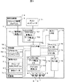
図1は、本発明を適用したストレージシステム1の構成を示す。ストレージシステム1は、複数のハードディスク6、ホストコンピュータ71とのやり取りを行うためのホストI/F部72、ハードディスク6とのデータやり取りをするためのディスクI/F部74、ハードディスク6に格納されているデータの一部に高速にアクセスするためのデータを格納するキャッシュメモリ部73、ストレージシステム1の全体制御を行う制御部75、管理用端末4との情報のやり取りを行う管理端末用I/F部77及びこれらの間を互いに接続する接続を行うスイッチ部76で構成される。
FIG. 1 shows a configuration of a
ホストI/F部72の構成は以下の通りである。ホストI/F部72は、ホストコンピュータ71との接続に用いられるFibre Channel等のプロトコルと、ストレージ内部で用いられるPCI等のプロトコルとの変換を行うプロトコル変換LSI721及び制御部75からの指示に従ってプロトコル変換LSI721とキャッシュメモリ部73とのデータ転送を行うデータ転送LSI722で構成される。
The configuration of the host I /
ディスクI/F部74の構成は以下の通りである。ディスクI/F部74は、ハードディスク6との接続に用いられるFibreChannelやSAS(Serial Attached SCSI)などのプロトコルと、ストレージ内部で用いられるプロトコルとの変換を行うプロトコル変換LSI741、制御部75からの指示に従ってハードディスク6とキャッシュメモリ部73とのデータ転送を行うデータ転送LSI742で構成される。
The configuration of the disk I /
制御部75の構成は以下の通りである。制御部75は、プロセッサ78と制御メモリ79とで構成される。プロセッサ78は、複数のプロセッサコア781を持ってもよい。プロセッサ78ではストレージ1を制御するストレージ制御プログラム2が動作し、ストレージシステム1内のデータ転送等の制御を行う。制御メモリ79には前述のストレージ制御プログラム2とストレージ制御に必要な情報である制御データ3が格納されている。
The configuration of the
管理用端末4の構成は以下の通りである。管理用端末4には、ストレージシステム1の管理を行うストレージ管理プログラム5が格納されており、このプログラムによって、ストレージシステム1の管理を行うことができる。
The configuration of the
図2は、ストレージ制御プログラム2が持つ機能である。ストレージ制御プログラム2は、ホストI/O受領機能21、ディスクI/O発行機能22、ディスクI/O完了処理機能23及び電力推定機能24で構成される。
FIG. 2 shows the functions of the
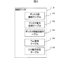
図3は、制御データ3の構成である。制御データ3は、ディスク部構成テーブル31、ディスク電力仕様テーブル32、ディスク稼働記録テーブル33、Tag管理テーブル34、I/O発行状況テーブル35で構成される。
FIG. 3 shows the configuration of the
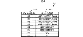
図4は、ディスク部構成テーブル31の一例である。ディスク部構成テーブル31はストレージシステム1に搭載されているハードディスク6の種別及び搭載位置等を記録するためのもので、ディスク6の増設や減設の際に更新される。また、電力推定機能24で電力を推定する際に参照される。
FIG. 4 is an example of the disk unit configuration table 31. The disk unit configuration table 31 is for recording the type and mounting position of the
ディスク番号311は、ディスク6が搭載される位置即ちスロット番号等を示す。ディスク型番312は、そのディスク番号に対応する位置に、どの種別のディスクが搭載されているかを示す。
The
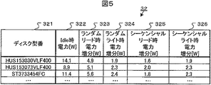
図5は、ディスク電力仕様テーブル32の一例である。ディスク電力仕様テーブル32は、ストレージシステム1に搭載されているハードディスク6の種別毎に、様々な状態での消費電力を保持するためのものであり、新規種別のハードディスクが追加された際に更新される。また、電力推定機能24で電力を推定する際に参照される。
FIG. 5 is an example of the disk power specification table 32. The disk power specification table 32 is for holding power consumption in various states for each type of the
ディスク型番321は、ディスクの種別を識別するためのもので、ハードディスクの型番など、電力に関する仕様が異なるもの毎に、それらが識別可能なものを用いる。Idle時電力322は、対応するハードディスク6がアイドル状態であるときの消費電力を示す。ここで、アイドルとは、電源が入っており、ディスクI/F部74からのアクセスを受け付け可能であるが、アクセスが来ていない状態のことである。
The disk model number 321 is used to identify the type of the disk, and a disk model that can be identified is used for each disk having different power-related specifications such as a model number of the hard disk. The
ランダムリード時電力増分323は、対応するハードディスクがランダムリードのみを受け付けている状態で且つ限界まで稼働している状態における、アイドル時電力との差分を示す。ここで、ランダムリードとはホストコンピュータ71がディスクの全体に対し、局所性が無くリードアクセスを発行している状態のことであり、限界まで稼働している状態とは、常にディスクアクセスを処理中である状態のことである。
The random read power increment 323 indicates the difference from the idle power when the corresponding hard disk is accepting only random reads and is operating to the limit. Here, the random read is a state in which the
ランダムライト時電力増分324は、対応するハードディスク6がランダムライトのみを受け付けている状態で且つ限界まで稼働している状態における、アイドル時電力との差分を示す。ここで、ランダムライトとは、ホストコンピュータ71がディスクの全体に対し、局所性が無くライトアクセスを発行している状態のことである。
The random write power increment 324 indicates a difference from the idle power when the corresponding
シーケンシャルリード時電力増分325は、対応するハードディスク6がシーケンシャルリードのみを受け付けている状態で且つ限界まで稼働している状態における、アイドル時電力との差分を示す。ここで、シーケンシャルリードとは、ホストコンピュータ71がハードディスク6の連続した領域に対し、順番にリードアクセスを発行している状態のことである。
The sequential
シーケンシャルライト時電力増分326は、対応するハードディスク6がシーケンシャルライトのみを受け付けている状態で且つ限界まで稼働している状態における、アイドル時電力との差分を示す。ここで、シーケンシャルライトとは、ホストコンピュータ71がハードディスク6の連続した領域に対し、順番にライトアクセスを発行している状態のことである。
Sequential write power increment 326 indicates the difference from idle power when the corresponding
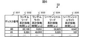
図6は、ディスク稼働記録テーブル33の一例である。ディスク稼働記録テーブル33は、ストレージシステム1が稼働している間に、ハードディスク6にどの程度アクセスしたかを記録するためのもので、ハードディスク6にアクセスする毎に更新される。また、電力推定機能24で電力を推定する際に参照される。
FIG. 6 is an example of the disk operation record table 33. The disk operation record table 33 is used to record the degree of access to the
ディスク番号331は、ハードディスク6が搭載されている位置を示す。ランダムリード累計稼働時間332は、対応するハードディスク6に対してランダムリードアクセスが発行されていた時間の累計である。ランダムライト累計稼働時間333、シーケンシャルリード累計稼働時間334、シーケンシャルライト累計稼働時間335についても同様である。
The
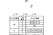
図7は、Tag管理テーブルの34の一例である。Tag管理テーブル34は、各ハードディスク6に対し発行中のアクセスについて、アクセス毎の識別子であるTagを記録し、一つのハードディスク6に対して多重にアクセスを発行している場合でも、応答がどのアクセス要求に対するものであるかを識別するためのものである。ディスク番号341は、ハードディスク6が搭載されている位置(スロット番号等)を示す。Tag番号342は、同時にアクセスを発行中のハードディスク6に対し、一意に付与される番号であり、アクセス発行時に指定する番号である。アクセス種別343は、ハードディスク6にアクセスすることになった契機である。
FIG. 7 is an example of the Tag management table 34. The tag management table 34 records the tag, which is an identifier for each access, for the access that is being issued to each
図8は、I/O発行状況テーブル35の一例である。I/O発行状況テーブル35は、各ハードディスク6に対し、どの種別のアクセスを発行しているか又その発行開始時刻がいつであるかを記録するためのもので、ディスクI/O発行機能22でハードディスク6へのアクセスを新規に発行した際及びディスクI/O完了処理機能23でハードディスク6からの応答を処理した際に参照・更新される。
FIG. 8 is an example of the I / O issue status table 35. The I / O issue status table 35 is used to record which type of access is issued to each
ディスク番号351は、ハードディスク6が搭載されている位置(スロット番号等)を示す。アクセス種別352は、表右側の現在発行中コマンド数353及びディスク稼働開始時刻354が、どの種別のアクセスに関する情報であるかを示す。現在発行中コマンド数353は、対応するディスク番号・アクセス種別のアクセスが、ハードディスク6に対し、現在いくつ発行中であるかを示す。ディスク稼働開始時刻354は、対応するディスク番号・アクセス種別のアクセスが発行された時刻を、ストレージシステム1が起動してからの経過時間(μs)で示す。
The
図9はホストI/O受領機能21の一例である。ホストI/O受領機能21は、ホストコンピュータ71からリード要求、ライト要求等のコマンドを受け取った際に呼び出される機能で、コマンドの種別を判別し、ハードディスク6にアクセスする必要があるか否かなどを判断する。以下、ホストI/O受領機能21の処理を順に説明する。
FIG. 9 shows an example of the host I /
本機能が呼び出されると、ホストI/O受領機能21は、まず、ホストからのアクセス要求を解析する(S2101)。ここで、アクセス種別とは、リード/ライトの種別及びそれがシーケンシャルアクセスであるか、ランダムアクセスであるかの種別である。そして、ホストI/O受領機能21は、アクセス種別によって、以後の処理を分岐する(S2102)。
When this function is called, the host I /
もし、ランダムリードの場合、ホストI/O受領機能21は、キャッシュメモリ部73上に、要求されたデータが有るか(キャッシュヒット)否かを判定する(S2111)。存在しなかった場合は、ホストI/O受領機能21は、ディスクI/O発行機能22を起動する。このとき、ホストI/O受領機能21は、アクセス種別毎のアクセス時間を集計するために、ディスクアクセスを発行する契機を合わせてパラメータとして与える。即ちホストI/O受領機能21は、契機をランダムリード、アクセスの転送元をホストが要求したデータが存在するディスクのアドレス又転送先をキャッシュメモリ部73上の空き領域として、ディスクI/O発行機能22を起動し(S2112)、S2113に進む。
一方、S2111において、キャッシュメモリ部73上にデータが存在した場合(キャッシュヒット)は(S2111:Yes)、ホストI/O受領機能21は、そのデータをホストコンピュータ71への応答として送信する(S2113)。
If the read is random, the host I /
On the other hand, if data exists in the
S2102において、アクセス種別がランダムライトの場合について述べる。この場合、まず、ホストI/O受領機能21は、ホストコンピュータ71から送られたデータをキャッシュメモリ部73へ書き込む(S2121)。そして、ホストI/O受領機能21は、ホストコンピュータ71に対し、ライト完了を応答する(S2122)。次に、ホストI/O受領機能21は、キャッシュメモリ部73の空き領域が十分であるかどうかを判定する(S2123)。
もし、空き領域が十分にある場合は、ホストI/O受領機能21は、そのまま処理を終了する。
一方、空き領域が十分にない場合、このままではホストコンピュータ71からのライトを受けられなくなるため、ディスク6にライトデータの書き込みを行う必要がある。この場合では、ホストI/O受領機能21は、アクセス契機をランダムライトとし、転送元をキャッシュメモリ部73上の最近アクセスされていない領域とし、転送先をアクセスされていない領域に対応するハードディスク6の対応するアドレスとして、ディスクI/O発行機能22を起動する(S2124)。
A case where the access type is random write in S2102 will be described. In this case, first, the host I /
If there is sufficient free space, the host I /
On the other hand, if there is not enough free space, it is not possible to receive a write from the
S2102において、アクセス種別がシーケンシャルリードの場合について述べる。シーケンシャルアクセスの場合、ホストI/O受領機能21は、ホストコンピュータ71からアクセスがあることを予見し先読みを行っているので、ホストコンピュータ71から要求されたデータはキャッシュメモリ部73上に存在する。そのため、ホストI/O受領機能21は、そのデータをホストコンピュータ71への応答として送信する(S2131)。そして、ホストコンピュータ71が後に次の領域へアクセスすることが予見されるため、ホストI/O受領機能21は、次の領域のデータをあらかじめキャッシュメモリ部73に読みだしておく。即ちホストI/O受領機能21は、アクセス契機をシーケンシャルリードとし、転送元をホストコンピュータ71が要求した領域の次の領域とし又転送先をキャッシュメモリ部73上の空き領域として、ディスクI/O発行機能22を起動する(S2132)。
A case where the access type is sequential read in S2102 will be described. In the case of sequential access, since the host I /
最後に、S2102において、アクセス種別がシーケンシャルライトの場合について述べる。この場合、ホストI/O受領機能21は、まず、ホストから送られたデータをキャッシュメモリ部73へ書き込む(S2141)。そして、ホストI/O受領機能21は、ホストコンピュータ71に対し、ライト完了を応答する(S2142)。シーケンシャルライトの場合、同じ領域に対して再度書き込みが行われる可能性は低い傾向がある。このため、書き込まれたデータをそのままキャッシュメモリ部73に保持してもキャッシュヒットを利用した性能面での効果を期待できない場合も多い。従って、直ちにホストコンピュータ71から書かれたデータをハードディスク6に退避するのが好ましい。具体的には、ホストI/O受領機能21は、アクセス契機をシーケンシャルライト、転送元をホストが書いたキャッシュメモリ上の領域又転送先を対応するハードディスク6の対応するアドレスとして、ディスクI/O発行機能22を起動する(S2143)。
Finally, a case where the access type is sequential write in S2102 will be described. In this case, the host I /
図10は、ディスクI/O発行機能22の一例である。ディスクI/O発行機能22は、ハードディスク6へのアクセスを発行する機能で、ホストI/O受領機能21から必要に応じて呼び出される。
FIG. 10 shows an example of the disk I /
以下、ディスクI/O発行機能22の処理を順に説明する。
本機能が呼び出されると、ディスクI/O発行機能22は、まず、呼び出し元であるホストI/O受領機能21から渡されたパラメータを解析し、アクセス先ハードディスク6及びアクセス種別を識別する(S221)。そして、ディスクI/O発行機能22は、Tag管理テーブル34を参照し、空いているTag番号即ちTag番号に対応するアクセス種別が記入されていないTag番号を選ぶ(S222)。
そして、ディスクI/O発行機能22は、Tag管理テーブル34から選んだTag番号に対応するエントリのアクセス種別343に、先ほど解析したアクセス種別を記入する(S223)。
そして、ディスクI/O発行機能22は、ディスクI/F部74のプロトコル変換LSI741に、ディスクアクセスコマンドを送信する(S224)。
その後、ディスクI/O発行機能22は、I/O発行状況テーブル35を参照し、アクセス先ハードディスク(ディスク番号)、アクセス種別に対応するエントリについて、発行中コマンド数353が「0」であるかどうかを調べる(S225)。
もし、「0」の場合(S225:YES)、これまで稼働していなかったことになるため、ディスクI/O発行機能22は、I/O発行状況テーブル35の対応するエントリについて、ディスク稼働開始時刻354に現在時刻を書き込み(S226)、S227に進む。
一方、S225において、発行中コマンド数が「0」でない場合(S225:NO)、ディスクI/O発行機能22は、既に同種のアクセスが同じハードディスクへ発行中即ち既に稼働中のため、そのままS227に進む。
そして、ディスクI/O発行機能22は、I/O発行状況テーブル35の対応するエントリについて、発行中コマンド数353を1増やし(S227)、処理を終了する。
Hereinafter, the processing of the disk I /
When this function is called, the disk I /
Then, the disk I /
Then, the disk I /
After that, the disk I /
If it is “0” (S225: YES), it means that the disk I /
On the other hand, if the number of commands being issued is not “0” in S225 (S225: NO), the disk I /
Then, the disk I /
図11は、ディスクI/O完了処理機能23の一例である。ディスクI/O完了処理機能23は、ディスクI/O発行機能22で発行したディスクアクセスコマンドに対する応答をハードディスク6から受け取った際に呼び出される機能である。ディスクI/O完了処理機能23は、後述する電力推定に必要となる、アクセスに要した時間を記録する。
FIG. 11 shows an example of the disk I / O
以下、ディスクI/O完了処理機能23の処理を順に説明する。
本機能では、まず、ハードディスク6からの応答を解析し、Tag番号を抽出する(S231)。そして、ディスクI/O完了処理機能23は、Tag管理テーブル34を参照し、抽出したTag番号に対応するエントリのアクセス種別343を読み出す(S232)。そして、ディスクI/O完了処理機能23は、Tag管理テーブル34上から前記エントリのアクセス種別を消去する(S233)。そして、I/O発行状況管理テーブル35について、ディスク番号及びアクセス種別に対応するエントリの発行中コマンド数353を1減らす(S234)。
次に、ディスクI/O完了処理機能23は、I/O発行状況管理テーブル35の対応するエントリについて、発行中コマンド数353が「0」であるかどうかを判定する(S235)。
もし、「0」であった場合(S235:YES)、このアクセス種別のアクセスは1つも発行されていないことになるので、ディスクI/O完了処理機能23は、これまでのアクセス時間を稼働情報として記録する。即ちI/O発行状況管理テーブル35内の対応するエントリのディスク稼働開始時刻354と、現在時刻の差分を計算し、ディスク稼働記録テーブル33の対応するエントリに対応するアクセス種別の累計稼働時間即ち332〜335のいずれかに加算する(S236)。そして、ディスクI/O完了処理機能23は、処理を終了する。
一方、S235において、発行中コマンド数が「0」でなかった場合(S235:NO)には、まだ他に同一アクセス種別のアクセスを実行中であるため、ディスクI/O完了処理機能23は、そのまま処理を終了する。
Hereinafter, the processing of the disk I / O
In this function, first, a response from the
Next, the disk I / O
If it is "0" (S235: YES), no access of this access type has been issued, so the disk I / O
On the other hand, if the number of commands being issued is not “0” in S235 (S235: NO), another access of the same access type is still being executed, so the disk I / O
図12は電力推定機能24の一例である。電力推定機能24は、ディスク稼働記録テーブル33の情報に基づいて、ストレージシステム1のハードディスク6が消費している消費電力を推定し、管理用端末4に推定結果を送信する機能である。
FIG. 12 shows an example of the
以下、電力推定機能24の処理を順に説明する。
本機能では、まず、ディスク部構成テーブル31とディスク電力仕様テーブル32とから、ディスク部定常消費電力を算出する(S241)。具体的には、各ハードディスク6の定常電力については、ディスク部構成テーブル31のエントリ毎にディスク型番を参照し、ディスク電力仕様テーブル32の対応するエントリのアイドル時電力322を定常電力とすれば良い。
次に、電力推定機能24は、ディスク稼働記録テーブル33の情報と、本電力推定機能24が呼び出される間隔との比から、各ハードディスク6のアクセス種別毎の稼働率を算出する(S242)。例えば、電力推定機能24の呼び出し間隔が1秒で、ディスク稼働記録テーブル33のランダムリード累計稼働時間332が1ミリ秒であれば、ランダムリード稼働率は1/1000となる。
次に、電力推定機能24は、求めた稼動率とディスク電力仕様テーブル32の情報から、各ディスクの電力増加分を算出する(S243)。例えば、稼働率が1/10で、ディスク電力仕様テーブル32の電力増加が4.9Wであれば、電力増加は0.49Wとなる。そして、電力推定機能24は、ステップS241で求めた定常消費電力と、ステップS243で求めた電力増加分とを管理用端末4に送信する(S244)。最後に、電力推定機能24は、ディスク稼働記録テーブル33の累計稼働時間332〜335を「0」に初期化する(S245)。
Hereinafter, the process of the
In this function, first, the disk unit steady power consumption is calculated from the disk unit configuration table 31 and the disk power specification table 32 (S241). Specifically, for the steady power of each
Next, the
Next, the
図13は、電力推定機能24が、S241及びS243で行うディスク部電力増加分を算出する方法の例である。電力仕様テーブル32に記載されているIdle時電力322から定常電力を、同じく電力仕様テーブル32に記載されているアクセス種別毎の電力増加分333〜336と電力推定機能24のS242で求めたアクセス種別毎の稼働率とから、アクセス種別毎の電力増加分を求める。
FIG. 13 shows an example of a method by which the
図14は、電力推定機能24がS244で管理用端末4に送信するデータの例である。部位991は右側の欄の消費電力がどのハードディスクのものであるかあるいはその合計値であるかを示す。平均消費電力992は、各ハードディスク及び合計について、前回の送信以降の平均消費電力を示す。ディスク部電力増加993は、電力増加量及びそのアクセス種別毎の内訳である。また、Idle時電力994は、全くアクセスが発生していないときの電力である。
FIG. 14 is an example of data that the
図15はストレージ管理プログラム5の構成である。ストレージ管理プログラムは、消費電力履歴テーブル51及び消費電力更新機能52で構成される。
FIG. 15 shows the configuration of the
図16は、消費電力履歴テーブル51の例である。消費電力履歴テーブル51は、ストレージシステム1から送られた電力データを記録し、管理用端末利用者からの要求に応じてその内容を管理用端末4に設けられたモニタ画面に表示するために用いられる。日時511は、このデータがいつの情報であるかを示す。他の項目については、図14に示す、電力推定機能24が管理用端末4に送信するデータの項目と同様である。
FIG. 16 is an example of the power consumption history table 51. The power consumption history table 51 is used for recording power data sent from the
図17は、消費電力更新機能52の一例である。消費電力更新機能52は、ストレージシステム1から消費電力の最新データを受け取り、保管すると共に管理用端末の表示を更新する機能である。
FIG. 17 is an example of the power
以下、消費電力更新機能52の処理を順に説明する。
本機能ではまず、ストレージ装置1から、消費電力データを受け取る(S521)。そして、消費電力更新機能52は、受け取った消費電力データを消費電力履歴テーブル51の新規エントリに追加する(S522)。最後に、消費電力更新機能52は、管理用端末4の消費電力表示画面を、ストレージ装置1から受け取った最新の情報を含めた内容に更新する(S523)。
Hereinafter, processing of the power
In this function, first, power consumption data is received from the storage apparatus 1 (S521). Then, the power
以上、本発明を適用した実施例1のストレージシステム1によれば、電力計を用いなくても、ストレージシステムに搭載されているハードディスクの消費電力を求めることができ、より精度の高い電力制御を行うことが可能となり、更に、管理者がその情報を知ることが可能になる。
As described above, according to the
本実施例は、実施例1で用いたディスク電力仕様テーブル32、の値を設定する例である。本実施例では、管理端末4から管理者又は保守員が入力することにより、ディスク電力仕様テーブル32の値を設定する。以下、図を用いて説明する。
In this embodiment, the values of the disk power specification table 32 used in the first embodiment are set. In this embodiment, the value of the disk power specification table 32 is set by an administrator or maintenance personnel inputting from the
図18は、管理用端末4で機能するストレージ管理プログラム5の例である。ストレージ管理プログラムは、実施例1の機能に加え、ストレージ管理プログラム増設処理機能55を持つ。
FIG. 18 is an example of the
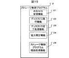
図19は、ストレージ制御プログラム2の例である。ストレージ制御プログラムは、実施例3の機能に加え、ストレージ制御プログラム増設処理機能28を持つ。
FIG. 19 is an example of the
図20は、ストレージ制御プログラム増設処理機能28の例である。本機能は、ストレージシステムに部品が増設された場合に呼び出され、増設した部品を識別すると共に、取得した部品の種別を管理用端末4に送信し、電力情報を得る。
FIG. 20 shows an example of the storage control program
以下、本機能の処理を順に説明する。
本機能ではまず、増設された部品を識別し、型名などの識別子を得る(S281)。識別の方法は、部品に搭載されている不揮発メモリ上に存在する型名を読む方法などが考えられる。増設された部品の情報が、ディスク電力仕様テーブル32、に存在するかどうかを調べる(S282)。もし、存在する場合は、そのまま処理を終了する。存在しなかった場合は、増設された部品の識別子を管理用端末4に送信する(S283)。そして、管理用端末4から、増設された部品の電力情報を受信する(S284)。最後に、受信したデータをディスク電力仕様テーブル32に追加する。
Hereinafter, processing of this function will be described in order.
In this function, first, the added parts are identified to obtain an identifier such as a model name (S281). As a method of identification, a method of reading a type name existing on a nonvolatile memory mounted on a component can be considered. It is checked whether or not the added component information exists in the disk power specification table 32 (S282). If it exists, the process ends. If not, the identifier of the added part is transmitted to the management terminal 4 (S283). Then, the power information of the added parts is received from the management terminal 4 (S284). Finally, the received data is added to the disk power specification table 32.
図21は、ストレージ管理プログラム増設処理機能55の例である。本機能は消費電力等が未知のディスク装置がストレージシステム1に増設された際に、ストレージシステム1からの要求によって呼び出され、管理者や保守員からの入力によって電力データを取得し、取得した電力データをストレージシステム1に送信する。
FIG. 21 shows an example of the storage management program
以下、本機能の処理を順に説明する。
本機能では、まず、ストレージシステム1から、増設されたディスク装置の種別、型名を受信する(S551)。そして、ストレージ管理プログラム増設処理機能55は、増設されたディスク装置の種別に応じて、ディスク種別追加画面59を表示する(S552)。そして、ストレージ管理プログラム増設処理機能55は、このディスク種別追加画面59を介して管理者等から入力された電力データをストレージコントローラに送信し(S553)、処理を終了する。
Hereinafter, processing of this function will be described in order.
In this function, first, the type and model name of the added disk device are received from the storage system 1 (S551). Then, the storage management program
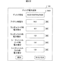
図22は、ストレージ管理プログラム増設処理機能55のS552で表示するディスク種別追加画面59の例である。ディスク型名593は、新たに追加されたディスク装置の種別である。以下、それぞれの入力パラメータは、ディスク電力仕様テーブル32の各項目に対応する。即ち管理者が、「アイドル時電力」、「ランダムリード時電力増分」、「ランダムライト時電力増分」、「シーケンシャルリード時電力増分」及び「シーケンシャルライト時電力増分」の各項目欄の一部又は全部に所定の電力値を入力し、「追加ボタン」を押下することで、ディスク電力仕様テーブル32に、追加されたディスク装置の各電力値が設定されるようになっている。
FIG. 22 is an example of the disk
以上により、電力が未知のディスク装置が追加された場合にもその情報を得ることができ、これらを含めた電力推定が可能となる。 As described above, even when a disk device whose power is unknown is added, the information can be obtained, and power estimation including these can be performed.
本実施例は、実施例2で、管理者等によって直接入力させていた電力に関する情報をディスク装置に埋め込んだ状態で出荷し、運用される場所でディスク装置が増設された際、埋め込まれたデータを用いてテーブルを更新する例である。以下、実施例2との差分を、図を用いて説明する。
In this embodiment, the information related to the power directly inputted by the administrator or the like in
図23は、ハードディスク6の構成である。ハードディスク6は、ユーザーのデータを記録する記録部61、記録部61の制御を行うと共にストレージ装置1の制御部75とデータ及びコマンドのやり取りを行うHDDコントローラ62及び不揮発メモリ63で構成される。不揮発メモリ63には、このハードディスクの消費電力仕様を示す電力情報テーブル64が格納される。
FIG. 23 shows the configuration of the
図24は、電力情報テーブル64の例である。電力情報テーブル64には、ディスクの型式名641、アイドル状態での消費電力642及び各状態での電力増分643〜646が記録される。
FIG. 24 is an example of the power information table 64. In the power information table 64, a
図25は、ストレージ制御プログラム2の例である。ストレージ制御プログラムは、実施例1の機能に加え、ストレージ制御プログラム増設処理機能28を持つ。
FIG. 25 is an example of the
図26は、ストレージ制御プログラム増設処理28の例である。本機能は、ディスク装置が新たに増設された際に呼び出され、必要に応じて電力情報を不揮発メモリ63から電力情報テーブル64の情報を読み出し、ディスク電力仕様テーブル32に追加する。
FIG. 26 shows an example of the storage control
以下、本処理を順に説明する。
本機能ではまず、増設されたハードディスク6を識別し、型名などの識別子を得る(S281)。識別の方法は、ハードディスク6に搭載されている不揮発メモリ63上に存在する型名を読む方法などが考えられる。ストレージ制御プログラム増設処理機能28は、増設されたハードディスク6の情報が、ディスク電力仕様テーブル32に存在するかどうかを調べる(S282)。
もし、存在する場合は、ストレージ制御プログラム増設処理機能28は、そのまま処理を終了する。
存在しなかった場合は、ストレージ制御プログラム増設処理機能28は、増設されたハードディスク6の電力情報テーブル64を読み出す(S283)。最後に、ストレージ制御プログラム増設処理機能28は、読み出したデータをディスク電力仕様テーブル32に追加する。
Hereinafter, this processing will be described in order.
In this function, first, the added
If it exists, the storage control program
If it does not exist, the storage control program
以上により、人による入力が困難な場合でも、新規(増設)ハードディスクの電力データを取得し、それに基づいた電力推定が可能となる。 As described above, even when it is difficult for human input, it is possible to acquire power data of a new (additional) hard disk and estimate power based on the acquired power data.
本実施例は、電力仕様が未知のハードディスクが増設された際に、電力計を用いてそのハードディスクの電力データを取得する例である。以下、実施例2との差について図を用いて説明する。 In this embodiment, when a hard disk with an unknown power specification is added, the power data of the hard disk is acquired using a power meter. Hereinafter, differences from the second embodiment will be described with reference to the drawings.
図27は、本実施例が適用されるシステムの構成である。ストレージシステム1と電源102の間に電力計101が挿入されており、ストレージシステム1全体の電力を測定することができる。なお、電力計101は増設時のみ存在すれば良く、通常稼働時に設置されていなくても良い。
FIG. 27 shows a system configuration to which this embodiment is applied. A
図28は、ストレージ制御プログラム2の構成である。ストレージ制御プログラム2は、実施例2に加え、ハードディスク消費電力測定機能81を有する。
FIG. 28 shows the configuration of the
図29は、ストレージ制御プログラム増設処理機能28の例である。本機能は新たにハードディスクが増設された際に呼び出され、増設されたハードディスクの電力仕様を求め、ディスク電力仕様テーブル32に追加する。
FIG. 29 shows an example of the storage control program
以下、本機能の処理を順に説明する。
本機能ではまず、増設されたハードディスクを識別し、型名などの識別子を得る(S281)。識別の方法は、ハードディスクに搭載されている不揮発メモリ63上に存在する型名を読む方法などが考えられる。ストレージ制御プログラム増設処理機能28は、増設されたハードディスク6の情報が、ディスク電力仕様テーブル32に存在するかどうかを調べる(S282)。
もし、存在する場合は、ストレージ制御プログラム増設処理機能28は、そのまま処理を終了する。
存在しなかった場合は、ストレージ制御プログラム増設処理機能28は、ハードディスク電力測定機能81を呼び出す(S284)。
ハードディスク電力測定機能81は、増設されたハードディスク6の各種電力を測定する機能部である。具体的な処理については後述する。ストレージ制御プログラム増設処理機能28は、ハードディスク消費電力測定機能81の測定により得られた増設ハードディスク6の各種電力データを、ディスク電力仕様テーブル32に追加し(S287)、処理を終了する。
Hereinafter, processing of this function will be described in order.
In this function, first, the added hard disk is identified to obtain an identifier such as a model name (S281). As a method of identification, a method of reading a model name existing on the
If it exists, the storage control program
If it does not exist, the storage control program
The hard disk power measurement function 81 is a functional unit that measures various powers of the added
図30はハードディスク消費電力測定機能81の処理例である。本機能では、消費電力等が未知のハードディスク6が増設された場合に、ストレージ制御プログラム増設処理機能28によって呼び出され、ハードディスク6に対し四種類のアクセスを発生させ、その時の電力変化を測定し、アクセスを発生させていないときの電力と併せ電力仕様として保存する。
FIG. 30 shows a processing example of the hard disk power consumption measuring function 81. In this function, when a
以下、本機能の処理を順に説明する。
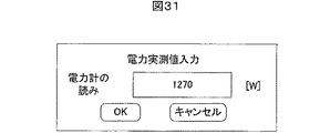
本機能ではまず、管理用端末4に対して、電力計101が示す現在のストレージシステム1の消費電力値を入力するための入力画面をモニタ装置に表示する指示を行う(S810)。そして、ハードディスク消費電力測定機能81は、管理者等によって入力された現在のストレージ装置1の消費電力値を管理用端末4から受け取り、ストレージシステム1全体のアイドル時の電力値とする(S811)。
次に、ハードディスク消費電力測定機能81は、ランダムリード、ランダムライト、シーケンシャルリード及びシーケンシャルライトの4種類のアクセスからまだ選択していない1のアクセスパターンを選択する(S812)。
そして、ハードディスク消費電力測定機能81は、選択したアクセスパターンをホストが発行してきたものとして、増設されたハードディスク6に対しアクセスを行う(S813)。
次に、ハードディスク電力測定機能81は、再度、電力計101が示す現在の消費電力値を管理者等が入力するための入力画面の表示を、管理用端末4に指示する(S814)。そして、ハードディスク電力測定機能81は、管理端末4の入力画面に入力された現在のストレージシステム1の消費電力値(増設ハードディスクに、ステップS812で選択したアクセスパターンでアクセスを行っている状態のストレージシステム1の消費電力値)を管理端末4から受け取り、ステップS811で取得したアイドル電力との差分を求める(S815)。即ちこの差分が、増設したハードディスク6における、特定のアクセスパターンでの消費電力の増分である。
次に、ハードディスク消費電力測定機能81は、4種類のアクセス全てに対して測定をしたかどうかを判定する(S816)。未測定のアクセスパターンがある場合、ハードディスク電力測定機能81は、ステップS812の処理に戻る。四種類全てについて行った場合ハードディスク電力測定機能81は、増設されたハードディスク6の電源をOFFする(S817)。
次に、ハードディスク電力測定機能81は、増設されたハードディスク6の電源をOFFした状態の現在のストレージシステム1に対して電力計10が示す消費電力値を入力するための入力画面の表示を管理用端末4に対し指示する(S818)。そして、ハードディスク電力測定機能81は、管理者等から入力された現在のストレージシステム1の消費電力値を管理端末4から受け取り、ステップS811で取得したアイドル時電力との差分を求める(S819)。即ちこの差分が増設ハードディスクのアイドル時電力である。その後、ハードディスク消費電力測定機能81は処理を終了する。
Hereinafter, processing of this function will be described in order.
In this function, first, the
Next, the hard disk power consumption measuring function 81 selects one access pattern that has not yet been selected from the four types of access, that is, random read, random write, sequential read, and sequential write (S812).
Then, the hard disk power consumption measuring function 81 accesses the added
Next, the hard disk power measurement function 81 again instructs the
Next, the hard disk power consumption measurement function 81 determines whether or not measurement has been performed for all four types of accesses (S816). If there is an unmeasured access pattern, the hard disk power measurement function 81 returns to the process of step S812. When all four types have been performed, the hard disk power measurement function 81 turns off the power of the added hard disk 6 (S817).
Next, the hard disk power measurement function 81 is for managing the display of an input screen for inputting the power consumption value indicated by the
図32は、管理用端末の電力入力画面の例である。この画面により、保守員または管理者に現在の電力計の読みを入力させるようになっている。 FIG. 32 is an example of the power input screen of the management terminal. This screen allows the maintenance staff or administrator to input the current wattmeter reading.
以上のように、増設したハードディスクの電力仕様が未知の場合でも、簡便に消費電力仕様を求めることができる。 As described above, even when the power specification of the added hard disk is unknown, the power consumption specification can be easily obtained.
なお、本実施例では電力計の読みを人が入力しているが、電力計が測定値を管理端末に送信する機能を持っている場合にはそれで代用できる。また、増設したハードディスクの電源OFFの代わりに増設するハードディスクと同種のハードディスクを減設/増設させても良い。 In this embodiment, the person inputs the reading of the power meter, but if the power meter has a function of transmitting the measured value to the management terminal, it can be substituted. Further, a hard disk of the same type as the hard disk to be added may be reduced / added instead of turning off the power of the added hard disk.
1 ストレージシステム
2 ストレージ制御プログラム
3 制御データ
4 管理用端末
5 ストレージ管理プログラム
6 ハードディスク
21 ホストI/O受領機能
22 ディスクI/O発行機能
23 ディスクI/O完了処理機能
24 電力推定機能
31 ディスク部構成テーブル
32 ディスク電力仕様テーブル
33 ディスク稼動記録テーブル
34 Tag管理テーブル
35 I/O発行状況テーブル
59 ディスク種別追加画面
61 記録部
62 HDDコントローラ
63 不揮発メモリ
64 電力情報テーブル
72 ホストI/F部
73 キャッシュメモリ部
74 ディスクI/F部
75 制御部
76 スイッチ部
77 管理用端末I/F部
78 プロセッサ
79 制御メモリ
101 電力計
102 電源
DESCRIPTION OF
Claims (16)
前記I/O処理に応じて変動するディスク装置の消費電力を、前記I/O処理に要する電力情報と、所定単位時間当たりに前記I/O処理が要する時間の割合である稼働率とに基づいて算出する制御部と、
前記制御部により算出された前記消費電力を表示する表示部と、
を有することを特徴とするストレージ装置。 A storage device that has a disk device and performs I / O processing of data stored in the disk device in response to an I / O request from a host device;
The power consumption of the disk device that fluctuates according to the I / O processing is based on the power information required for the I / O processing and the operation rate that is the ratio of the time required for the I / O processing per predetermined unit time. A control unit for calculating
A display unit for displaying the power consumption calculated by the control unit;
A storage apparatus comprising:
前記稼働率は、前記I/O処理の種別毎の稼働率であり、
前記制御部は、前記I/O処理の種別毎の電力情報と、前記I/O処理の種別毎の稼働率とに基づき、前記I/O処理の種別毎の消費電力を算出することを特徴とする請求項1に記載のストレージ装置。 The power information of the disk device is power information for each type of the I / O processing,
The operating rate is an operating rate for each type of the I / O processing,
The control unit calculates power consumption for each type of I / O process based on power information for each type of I / O process and an operation rate for each type of I / O process. The storage apparatus according to claim 1.
前記他のディスク装置にI/O処理を実行したときの前記ストレージ装置の第2消費電力情報を入力するインタフェース部と、
前記他のディスク装置の電源をOFFしたときの前記ストレージ装置の第3消費電力情報を入力するインタフェース部と、を更に有し、
前記制御部は、
入力された前記第1消費電力情報と、前記第2消費電力情報とに基づいて前記他のディスク装置のI/O処理時の増加消費電力を算出し、
入力された前記第2消費電力情報と、前記第1消費電力情報とに基づいて前記他のディスク装置の定常消費電力を算出し、
算出した前記増加消費電力及び前記定常消費電力を、前記I/O処理に要する電力情報として取得することを特徴とする請求項1〜7のいずれか一項に記載のストレージ装置。 An interface unit for inputting the first power consumption information of the storage device when another disk device is added;
An interface unit for inputting second power consumption information of the storage device when I / O processing is executed on the other disk device;
An interface unit for inputting third power consumption information of the storage device when the power of the other disk device is turned off;
The controller is
Based on the input first power consumption information and the second power consumption information, an increased power consumption during I / O processing of the other disk device is calculated,
Based on the input second power consumption information and the first power consumption information, steady power consumption of the other disk device is calculated,
The storage apparatus according to claim 1, wherein the calculated increased power consumption and the steady power consumption are acquired as power information required for the I / O processing.
前記I/O処理で消費する前記ディスク装置の電力情報と、前記I/O処理の時間が所定単位時間当たりに占める割合である稼働率とに基づいて該I/O処理で消費する前記ディスク装置の消費電力を算出する第1ステップと、
算出した前記消費電力を表示装置に表示する第2ステップと、
を含むことを特徴とするストレージ装置の電力推定方法。 A power estimation method for a storage device that has a disk device and performs I / O processing of data stored in the disk device in response to an I / O request from a host device,
The disk device consumed in the I / O processing based on the power information of the disk device consumed in the I / O processing and the operation rate that is the ratio of the time of the I / O processing per predetermined unit time A first step of calculating the power consumption of
A second step of displaying the calculated power consumption on a display device;
A power estimation method for a storage apparatus, comprising:
前記稼働率は、前記I/O処理の種別毎の稼働率であり、
前記第1ステップは、前記I/O処理の種別毎に消費する電力情報と、前記I/O処理の種別毎の稼働率とに基づき、前記I/O処理の種別毎の消費電力を算出することを特徴とする請求項9に記載のストレージ装置の電力推定方法。 The power information of the disk device is power information consumed for each type of the I / O processing,
The operating rate is an operating rate for each type of the I / O processing,
The first step calculates power consumption for each type of I / O process based on power information consumed for each type of I / O process and an operation rate for each type of I / O process. The power estimation method for a storage apparatus according to claim 9.
前記入力インタフェースから前記ディスク装置の電力情報を取得するステップと、
を更に備えることを特徴とする請求項9〜13のいずれか一項に記載のストレージ装置の電力推定方法。 Displaying an input interface for inputting power information of the disk device on the display device;
Obtaining power information of the disk device from the input interface;
The storage apparatus power estimation method according to any one of claims 9 to 13, further comprising:
前記他のディスク装置にI/O処理を実行したときの前記ストレージ装置の第2消費電力情報を入力するインタフェースを前記表示装置に表示するステップと、
前記他のディスク装置の電源をOFFしたときの前記ストレージ装置の第3消費電力情報を入力するインタフェースを前記表示装置に表示するステップと、
入力された前記第1消費電力情報及び前記第2消費電力情報を取得し、該第1消費電力情報及び該第2消費電力情報に基づいて前記他のディスク装置のI/O処理時の増加消費電力を算出するステップと、
入力された前記第2消費電力情報及び前記第1消費電力情報を取得し、該第2消費電力情報及び該第1消費電力情報とに基づいて前記他のディスク装置の定常消費電力を算出し、算出した前記増加消費電力及び前記定常消費電力を、前記I/O処理に要する電力情報として取得するステップとを含むことを特徴とする請求項9〜15のいずれか一項に記載のストレージ装置の電力推定方法。 Displaying on the display device an interface for inputting the first power consumption information of the storage device when another disk device is added;
Displaying on the display device an interface for inputting second power consumption information of the storage device when I / O processing is executed on the other disk device;
Displaying on the display device an interface for inputting third power consumption information of the storage device when the power of the other disk device is turned off;
The input first power consumption information and the second power consumption information are acquired, and the increased consumption during I / O processing of the other disk device based on the first power consumption information and the second power consumption information Calculating power,
Obtaining the input second power consumption information and the first power consumption information, calculating steady power consumption of the other disk device based on the second power consumption information and the first power consumption information; The calculated increase power consumption and the steady power consumption are acquired as power information required for the I / O processing. The storage apparatus according to any one of claims 9 to 15, Power estimation method.
Priority Applications (3)
| Application Number | Priority Date | Filing Date | Title |
|---|---|---|---|
| JP2008161129A JP5288899B2 (en) | 2008-06-20 | 2008-06-20 | Storage apparatus for estimating power consumption and power estimation method for storage apparatus |
| US12/200,242 US8400893B2 (en) | 2008-06-20 | 2008-08-28 | Storage apparatus and estimating method of power consumption for storage apparatus |
| EP09250307A EP2136285A3 (en) | 2008-06-20 | 2009-02-06 | Storage apparatus and estimating method of power consumption for storage apparatus |
Applications Claiming Priority (1)
| Application Number | Priority Date | Filing Date | Title |
|---|---|---|---|
| JP2008161129A JP5288899B2 (en) | 2008-06-20 | 2008-06-20 | Storage apparatus for estimating power consumption and power estimation method for storage apparatus |
Publications (2)
| Publication Number | Publication Date |
|---|---|
| JP2010003099A true JP2010003099A (en) | 2010-01-07 |
| JP5288899B2 JP5288899B2 (en) | 2013-09-11 |
Family
ID=41202446
Family Applications (1)
| Application Number | Title | Priority Date | Filing Date |
|---|---|---|---|
| JP2008161129A Expired - Fee Related JP5288899B2 (en) | 2008-06-20 | 2008-06-20 | Storage apparatus for estimating power consumption and power estimation method for storage apparatus |
Country Status (3)
| Country | Link |
|---|---|
| US (1) | US8400893B2 (en) |
| EP (1) | EP2136285A3 (en) |
| JP (1) | JP5288899B2 (en) |
Cited By (6)
| Publication number | Priority date | Publication date | Assignee | Title |
|---|---|---|---|---|
| JP2012068803A (en) * | 2010-09-22 | 2012-04-05 | Nec Personal Computers Ltd | Power consumption estimation system, information processing apparatus, power consumption estimation method, and program |
| US8433942B2 (en) | 2010-03-05 | 2013-04-30 | Hitachi, Ltd. | Storage apparatus and power consumption estimation method |
| JP2016071924A (en) * | 2014-09-22 | 2016-05-09 | エイチジーエスティーネザーランドビーブイ | Data storage devices with performance-aware power capping |
| JP2016076204A (en) * | 2014-09-22 | 2016-05-12 | エイチジーエスティーネザーランドビーブイ | Performance-aware power capping control of data storage devices |
| US9965206B2 (en) | 2015-10-23 | 2018-05-08 | Western Digital Technologies, Inc. | Enhanced queue management for power control of data storage device |
| KR20190066830A (en) * | 2017-12-06 | 2019-06-14 | 연세대학교 산학협력단 | Apparatus and method for estimatinig power |
Families Citing this family (19)
| Publication number | Priority date | Publication date | Assignee | Title |
|---|---|---|---|---|
| US8671412B2 (en) * | 2008-10-24 | 2014-03-11 | International Business Machines Corporation | Calculating and communicating level of carbon offsetting required to compensate for performing a computing task |
| US7983125B2 (en) * | 2008-10-27 | 2011-07-19 | Lsi Corporation | Table-driven power utilization metrics |
| JP2010128985A (en) * | 2008-11-28 | 2010-06-10 | Hitachi Ltd | Storage management server and storage configuration relocating method |
| US9778718B2 (en) * | 2009-02-13 | 2017-10-03 | Schneider Electric It Corporation | Power supply and data center control |
| US9519517B2 (en) | 2009-02-13 | 2016-12-13 | Schneider Electtic It Corporation | Data center control |
| JP5595109B2 (en) * | 2010-05-10 | 2014-09-24 | 株式会社Pfu | Power consumption estimation system, information processing apparatus, server device, power consumption estimation method and program |
| CN103026316B (en) * | 2010-07-29 | 2015-06-17 | 惠普发展公司,有限责任合伙企业 | Computer component power-consumption database |
| US8417898B2 (en) | 2010-10-07 | 2013-04-09 | Hitachi, Ltd. | Storage control apparatus and storage control apparatus control method |
| CN103399713B (en) * | 2013-08-02 | 2016-01-20 | 浙江大学 | The data buffering method of balance dynamic data attemper performance and solid-state disk service life |
| TW201516634A (en) * | 2013-10-16 | 2015-05-01 | Wistron Corp | Redundant array of independent disks storage device, server system, and power management method thereof |
| US20160041762A1 (en) | 2014-08-08 | 2016-02-11 | Kabushiki Kaisha Toshiba | Memory system, host device and information processing system |
| US10606642B1 (en) | 2014-09-16 | 2020-03-31 | Amazon Technologies, Inc. | Dynamic power budgets |
| CN105893282B (en) * | 2015-01-04 | 2019-11-12 | 伊姆西公司 | Hard disk mobile identification method and system |
| TWI545431B (en) | 2015-04-30 | 2016-08-11 | 群暉科技股份有限公司 | Method for performing power management in an electronic system, and associated apparatus |
| JP6294569B2 (en) * | 2015-06-19 | 2018-03-14 | 株式会社日立製作所 | Storage system and cache control method |
| US10198061B2 (en) | 2015-09-01 | 2019-02-05 | Toshiba Memory Corporation | Storage and storage system |
| US10599349B2 (en) * | 2015-09-11 | 2020-03-24 | Samsung Electronics Co., Ltd. | Method and apparatus of dynamic parallelism for controlling power consumption of SSDs |
| US10254985B2 (en) * | 2016-03-15 | 2019-04-09 | Western Digital Technologies, Inc. | Power management of storage devices |
| US11449245B2 (en) * | 2019-06-13 | 2022-09-20 | Western Digital Technologies, Inc. | Power target calibration for controlling drive-to-drive performance variations in solid state drives (SSDs) |
Citations (8)
| Publication number | Priority date | Publication date | Assignee | Title |
|---|---|---|---|---|
| JPH08221160A (en) * | 1995-02-17 | 1996-08-30 | Mitsubishi Electric Corp | Battery driven portable information equipment |
| JP2003242711A (en) * | 2002-02-12 | 2003-08-29 | Teac Corp | Information recording and/or reproducing method and information recording and/or reproducing device |
| US20040044914A1 (en) * | 2002-08-29 | 2004-03-04 | Gedeon Mazen G. | Apparatus and method for measuring and controlling power consumption of a computer system |
| JP2005148853A (en) * | 2003-11-11 | 2005-06-09 | Sony Corp | Data storage device |
| JP2005215856A (en) * | 2004-01-28 | 2005-08-11 | Ricoh Co Ltd | Information apparatus and recording medium |
| JP2006317355A (en) * | 2005-05-13 | 2006-11-24 | Ricoh Co Ltd | Power monitoring device, power monitoring technique, and power monitoring program |
| JP2008003719A (en) * | 2006-06-20 | 2008-01-10 | Hitachi Ltd | Storage system and memory control method achieving consistency between power saving and performance |
| US20080172567A1 (en) * | 2007-01-11 | 2008-07-17 | Seagate Technology, Llc | System and method of power management |
Family Cites Families (4)
| Publication number | Priority date | Publication date | Assignee | Title |
|---|---|---|---|---|
| JP2002197709A (en) * | 2000-10-18 | 2002-07-12 | Sony Corp | Recording and reproducing device, state detecting method and data output method, information processor and information processing method, and recording medium |
| US7664968B2 (en) * | 2005-06-09 | 2010-02-16 | International Business Machines Corporation | System and method for managing power usage of a data processing system subsystem |
| US7869965B2 (en) * | 2005-08-17 | 2011-01-11 | Oracle America, Inc. | Inferential power monitor without voltage/current transducers |
| JP4903409B2 (en) | 2005-09-13 | 2012-03-28 | 株式会社日立製作所 | Management apparatus, management method, and storage system |
-
2008
- 2008-06-20 JP JP2008161129A patent/JP5288899B2/en not_active Expired - Fee Related
- 2008-08-28 US US12/200,242 patent/US8400893B2/en not_active Expired - Fee Related
-
2009
- 2009-02-06 EP EP09250307A patent/EP2136285A3/en not_active Withdrawn
Patent Citations (8)
| Publication number | Priority date | Publication date | Assignee | Title |
|---|---|---|---|---|
| JPH08221160A (en) * | 1995-02-17 | 1996-08-30 | Mitsubishi Electric Corp | Battery driven portable information equipment |
| JP2003242711A (en) * | 2002-02-12 | 2003-08-29 | Teac Corp | Information recording and/or reproducing method and information recording and/or reproducing device |
| US20040044914A1 (en) * | 2002-08-29 | 2004-03-04 | Gedeon Mazen G. | Apparatus and method for measuring and controlling power consumption of a computer system |
| JP2005148853A (en) * | 2003-11-11 | 2005-06-09 | Sony Corp | Data storage device |
| JP2005215856A (en) * | 2004-01-28 | 2005-08-11 | Ricoh Co Ltd | Information apparatus and recording medium |
| JP2006317355A (en) * | 2005-05-13 | 2006-11-24 | Ricoh Co Ltd | Power monitoring device, power monitoring technique, and power monitoring program |
| JP2008003719A (en) * | 2006-06-20 | 2008-01-10 | Hitachi Ltd | Storage system and memory control method achieving consistency between power saving and performance |
| US20080172567A1 (en) * | 2007-01-11 | 2008-07-17 | Seagate Technology, Llc | System and method of power management |
Cited By (9)
| Publication number | Priority date | Publication date | Assignee | Title |
|---|---|---|---|---|
| US8433942B2 (en) | 2010-03-05 | 2013-04-30 | Hitachi, Ltd. | Storage apparatus and power consumption estimation method |
| JP2012068803A (en) * | 2010-09-22 | 2012-04-05 | Nec Personal Computers Ltd | Power consumption estimation system, information processing apparatus, power consumption estimation method, and program |
| JP2016071924A (en) * | 2014-09-22 | 2016-05-09 | エイチジーエスティーネザーランドビーブイ | Data storage devices with performance-aware power capping |
| JP2016076204A (en) * | 2014-09-22 | 2016-05-12 | エイチジーエスティーネザーランドビーブイ | Performance-aware power capping control of data storage devices |
| KR101831915B1 (en) * | 2014-09-22 | 2018-02-27 | 에이취지에스티 네덜란드 비.브이. | Performance-aware power capping control of data storage devices |
| US10146293B2 (en) | 2014-09-22 | 2018-12-04 | Western Digital Technologies, Inc. | Performance-aware power capping control of data storage devices |
| US9965206B2 (en) | 2015-10-23 | 2018-05-08 | Western Digital Technologies, Inc. | Enhanced queue management for power control of data storage device |
| KR20190066830A (en) * | 2017-12-06 | 2019-06-14 | 연세대학교 산학협력단 | Apparatus and method for estimatinig power |
| KR102052537B1 (en) * | 2017-12-06 | 2019-12-05 | 연세대학교 산학협력단 | Apparatus and method for estimatinig power |
Also Published As
| Publication number | Publication date |
|---|---|
| US8400893B2 (en) | 2013-03-19 |
| EP2136285A3 (en) | 2010-07-14 |
| US20090316541A1 (en) | 2009-12-24 |
| JP5288899B2 (en) | 2013-09-11 |
| EP2136285A2 (en) | 2009-12-23 |
Similar Documents
| Publication | Publication Date | Title |
|---|---|---|
| JP5288899B2 (en) | Storage apparatus for estimating power consumption and power estimation method for storage apparatus | |
| CN106484318B (en) | Data storage system, method and equipment | |
| US7340616B2 (en) | Power management of storage units in a storage array | |
| JP4920658B2 (en) | Power estimation method and computer system | |
| JP4496265B2 (en) | Information processing apparatus and failure sign determination method | |
| US8732487B2 (en) | Predictive computing device power management | |
| US7555666B2 (en) | Power profiling application for managing power allocation in an information handling system | |
| US8433942B2 (en) | Storage apparatus and power consumption estimation method | |
| KR102151628B1 (en) | Ssd driven system level thermal management | |
| US9684457B2 (en) | Gathering sensed data from devices to manage host command transmission and cooling of the devices | |
| KR100755583B1 (en) | Storage control apparatus capable of analyzing volume information and the control method thereof | |
| WO2002021245A1 (en) | Clock control method, device therefor, and medium | |
| US8601301B1 (en) | System and method for adjusting an idle time of a hardware device based on a pattern of user activity that indicates a period of time that the user is not in a predetermined area | |
| TW201205322A (en) | Computer component power-consumption database | |
| TWI512490B (en) | System for retrieving console messages and method thereof and non-transitory computer-readable medium | |
| CN105247492B (en) | Detection to the user behavior for using time series modeling | |
| US20090276647A1 (en) | Storage device power consumption state | |
| US20120159208A1 (en) | Software controlled power limiting in usb to sata bridge | |
| US10705580B2 (en) | Intelligent energy-optimization technique for computer datacenters | |
| US10146623B2 (en) | Indicating rebuild state of storage devices | |
| JP2007034669A (en) | Power consumption monitoring system, and method and program therefor | |
| JP5659054B2 (en) | System management apparatus, system management method, and system management program | |
| TWI612475B (en) | Server and control method thereof | |
| US20050171711A1 (en) | Method for reading battery status by operation system of portable computer | |
| JP2010157266A (en) | Information processing apparatus, failure sign determination method, and program |
Legal Events
| Date | Code | Title | Description |
|---|---|---|---|
| RD03 | Notification of appointment of power of attorney |
Free format text: JAPANESE INTERMEDIATE CODE: A7423 Effective date: 20100316 |
|
| RD04 | Notification of resignation of power of attorney |
Free format text: JAPANESE INTERMEDIATE CODE: A7424 Effective date: 20100329 |
|
| A621 | Written request for application examination |
Free format text: JAPANESE INTERMEDIATE CODE: A621 Effective date: 20100722 |
|
| A977 | Report on retrieval |
Free format text: JAPANESE INTERMEDIATE CODE: A971007 Effective date: 20120301 |
|
| A131 | Notification of reasons for refusal |
Free format text: JAPANESE INTERMEDIATE CODE: A131 Effective date: 20120306 |
|
| A521 | Written amendment |
Free format text: JAPANESE INTERMEDIATE CODE: A523 Effective date: 20120507 |
|
| A131 | Notification of reasons for refusal |
Free format text: JAPANESE INTERMEDIATE CODE: A131 Effective date: 20120821 |
|
| A521 | Written amendment |
Free format text: JAPANESE INTERMEDIATE CODE: A523 Effective date: 20121022 |
|
| TRDD | Decision of grant or rejection written | ||
| A01 | Written decision to grant a patent or to grant a registration (utility model) |
Free format text: JAPANESE INTERMEDIATE CODE: A01 Effective date: 20130507 |
|
| A61 | First payment of annual fees (during grant procedure) |
Free format text: JAPANESE INTERMEDIATE CODE: A61 Effective date: 20130604 |
|
| R150 | Certificate of patent or registration of utility model |
Ref document number: 5288899 Country of ref document: JP Free format text: JAPANESE INTERMEDIATE CODE: R150 |
|
| LAPS | Cancellation because of no payment of annual fees |