JP2010002848A - Key support device of piano - Google Patents
Key support device of piano Download PDFInfo
- Publication number
- JP2010002848A JP2010002848A JP2008163500A JP2008163500A JP2010002848A JP 2010002848 A JP2010002848 A JP 2010002848A JP 2008163500 A JP2008163500 A JP 2008163500A JP 2008163500 A JP2008163500 A JP 2008163500A JP 2010002848 A JP2010002848 A JP 2010002848A
- Authority
- JP
- Japan
- Prior art keywords
- key
- pin
- keyboard
- support device
- piano
- Prior art date
- Legal status (The legal status is an assumption and is not a legal conclusion. Google has not performed a legal analysis and makes no representation as to the accuracy of the status listed.)
- Granted
Links
Images


Landscapes
- Electrophonic Musical Instruments (AREA)
Abstract
Description
本発明は、鍵を揺動自在に支持するピアノの鍵支持装置に関する。 The present invention relates to a piano key support device for swingably supporting a key.
従来のこの種のピアノの鍵支持装置として、例えば、特許文献1に開示されたものが知られている。この鍵支持装置では、筬の前後方向の中央にバランスピンが立設され、筬の前端部にフロントピンが立設されている。鍵の中央には、上下方向に貫通するバランスピン孔が形成されており、このバランスピン孔がバランスピンに通されることにより、鍵は筬にバランスピンを中心として揺動自在に支持されている。また、鍵の前端部には、下面に開口するフロントピン穴が形成されており、このフロントピン穴がフロントピンに係合することによって、鍵の左右方向のぶれが規制される。これらのバランスピンおよびフロントピンは、通常、表面にニッケルメッキが施された真ちゅうで構成されている。 As a conventional key support device for this kind of piano, for example, the one disclosed in Patent Document 1 is known. In this key support device, a balance pin is erected at the center of the heel in the front-rear direction, and a front pin is erected at the front end of the heel. A balance pin hole penetrating in the vertical direction is formed in the center of the key. By passing the balance pin hole through the balance pin, the key is supported by the bag so as to be swingable around the balance pin. Yes. Further, a front pin hole that opens to the lower surface is formed at the front end portion of the key, and when the front pin hole engages with the front pin, the lateral movement of the key is restricted. These balance pins and front pins are usually made of brass with nickel plating on the surface.
さらに、鍵のバランスピン孔およびフロントピン穴の左右の壁面には、人工皮革で構成された左右のブッシングクロスが貼り付けられている。押鍵に伴う鍵の揺動時、これらのブッシングクロスが、バランスピンやフロントピンに摺接することによって、鍵の滑らかな動作が確保されるとともに、雑音が防止される。 Further, left and right bushing cloths made of artificial leather are attached to the left and right wall surfaces of the balance pin hole and the front pin hole of the key. When the key swings when the key is pressed, these bushing cloths are in sliding contact with the balance pin and the front pin, so that the smooth operation of the key is ensured and noise is prevented.
しかし、ピアノの長期の使用により、鍵の押鍵が繰り返されると、鍵のブッシングクロスとこれに摺接するフロントピンやバランスピンとの摩擦によって、フロントピンなどの傷付きや、ブッシングクロスの摩耗および焼き付きが生じ、それにより、摩擦が増大することによって、鍵の滑らかな動作が阻害され、演奏に支障をきたすことがある。特に、フロントピンの場合には、鍵の支点から遠い位置に配置されているため、ブッシングクロスとの摩擦が大きくなりがちであることで、ブッシングクロスの摩耗などが生じやすいとともに、そのような摩耗などが一旦生じると、鍵の動作への悪影響が顕著に現われてしまう。このため、この従来の鍵支持装置では、ブッシングクロスとフロントピンとの良好な滑り性を長期間、維持するために、製造時にブッシングクロスやフロントピンにシリコンオイルなどの潤滑剤を塗布したり、あるいは、滑り性を維持または回復するためのメンテナンスを頻繁に行ったりすることが必要になる。 However, if the key is pressed repeatedly due to long-term use of the piano, the front pin or the like is scratched or the bushing cloth is worn and seized due to friction between the key bushing cloth and the front pin or balance pin that slides on the key. As a result, the friction increases and the smooth movement of the keys is hindered, which may hinder the performance. In particular, in the case of the front pin, since it is arranged at a position far from the fulcrum of the key, the friction with the bushing cloth tends to increase, and the wear of the bushing cloth is likely to occur and such wear. Once such a problem occurs, the adverse effect on the operation of the key becomes noticeable. For this reason, in this conventional key support device, a lubricant such as silicone oil is applied to the bushing cloth and the front pin during manufacturing in order to maintain a good slipping property between the bushing cloth and the front pin for a long time, or Therefore, it is necessary to frequently perform maintenance for maintaining or recovering the slipperiness.
本発明は、潤滑剤の塗布や頻繁なメンテナンスを必要とすることなく、鍵盤ピンの滑り性を長期間、維持することができるピアノの鍵支持装置を提供することを目的とする。 SUMMARY OF THE INVENTION An object of the present invention is to provide a piano key support device that can maintain the slidability of a keyboard pin for a long period of time without requiring application of a lubricant or frequent maintenance.
この目的を達成するために、請求項1に係る発明は、前後方向に延び、かつ下面に開口する係合孔を有し、係合孔の壁面にブッシングクロスが貼り付けられた鍵を揺動自在に支持するピアノの鍵支持装置であって、棚板の上面に載置された筬と、筬に立設され、鍵が係合孔を介して係合するとともに、押鍵に伴って鍵が揺動する際に、ブッシングクロスが摺動する鍵盤ピンと、を備え、鍵盤ピンの表面に、フッ素樹脂を含むコーティング層が形成されていることを特徴とする。 In order to achieve this object, the invention according to claim 1 swings a key having an engagement hole extending in the front-rear direction and opening in the lower surface, and a bushing cloth attached to the wall surface of the engagement hole. A key support device for a piano that is freely supported. The key support device is installed on the top surface of the shelf, and the key is engaged with the key through the engagement hole. And a keyboard pin on which the bushing cross slides, and a coating layer containing a fluororesin is formed on the surface of the keyboard pin.
この構成によれば、筬に立設された鍵盤ピンに、鍵の係合孔が係合しており、鍵が押鍵に伴って揺動する際に、係合孔に貼り付けられたブッシングクロスが鍵盤ピンに沿って摺動する。 According to this configuration, the key engagement hole is engaged with the keyboard pin erected on the ridge, and the bushing attached to the engagement hole when the key swings as the key is depressed. The cloth slides along the keyboard pins.
本発明によれば、鍵盤ピンの表面に、フッ素樹脂を含むコーティング層が形成されているので、鍵のブッシングクロスと鍵盤ピンとの間で発生する摩擦を低減することができる。それにより、鍵盤ピンの傷付きや、ブッシングクロスの摩耗および焼き付きが生じにくくなり、その結果、ブッシングクロスと鍵盤ピンとの摩擦を小さい状態に長時間、維持できる。これにより、潤滑剤の塗布や頻繁なメンテナンスを必要とすることなく、鍵盤ピンの滑り性を長期間、維持することができる。 According to the present invention, since the coating layer containing the fluororesin is formed on the surface of the keyboard pin, it is possible to reduce the friction generated between the key bushing cloth and the keyboard pin. As a result, scratches on the keyboard pins and wear and seizure of the bushing cloth are less likely to occur, and as a result, the friction between the bushing cloth and the keyboard pins can be maintained in a small state for a long time. Thereby, the slipperiness of the keyboard pin can be maintained for a long period of time without requiring application of a lubricant or frequent maintenance.
請求項2に係る発明は、請求項1に記載のピアノの鍵支持装置において、係合孔は、鍵の前端部に形成されたフロントピン穴であり、鍵盤ピンは、フロントピン穴が係合し、鍵を左右方向にぶれないように案内するためのフロントピンであることを特徴とする。
The invention according to
この構成によれば、鍵の前端部に形成されたフロントピン穴が、鍵盤ピンとしてのフロントピンに係合しており、フロントピンによる案内によって、鍵の左右方向のぶれが規制される。前述したように、フロントピンの場合には、鍵の支点から遠い位置に配置されているため、ブッシングクロスとの摩擦が大きくなりがちであることで、ブッシングクロスの摩耗などが生じやすいとともに、それによる鍵の動作への悪影響が顕著に現れやすい。 According to this configuration, the front pin hole formed in the front end portion of the key is engaged with the front pin as the keyboard pin, and the lateral movement of the key is restricted by the guide by the front pin. As described above, since the front pin is located far from the fulcrum of the key, the friction with the bushing cloth tends to increase, and the wear of the bushing cloth is likely to occur. The adverse effect on the key operation due to is prominent.
本発明によれば、フロントピンの表面にフッ素樹脂を含むコーティング層が形成されているので、前述した請求項1の作用を効果的に得ることができる。 According to the present invention, since the coating layer containing the fluororesin is formed on the surface of the front pin, it is possible to effectively obtain the operation of the first aspect described above.
請求項3に係る発明は、請求項1に記載のピアノの鍵支持装置において、鍵盤ピンの筬に埋め込まれる部位の表面に、鍵盤ピンの保持力を高めるための凹凸が形成されていることを特徴とする。 According to a third aspect of the present invention, in the piano key support device according to the first aspect, the surface of the portion embedded in the key pin ridge is provided with irregularities for increasing the holding force of the keyboard pin. Features.
この構成によれば、鍵盤ピンの筬に埋め込まれる部位の表面に凹凸が形成されており、この凹凸によって鍵盤ピンの保持力が高められる。したがって、鍵盤ピンにコーティング層が形成される鍵盤ピンの保持力の低下分を、凹凸による保持力で補うことができる。その結果、鍵盤ピンの保持力が保たれることによって、鍵盤ピンのぐらつきや筬からの離脱などを防止することができる。 According to this structure, the unevenness is formed on the surface of the portion embedded in the key pin ridge, and the holding force of the keyboard pin is enhanced by the unevenness. Therefore, the decrease in the holding force of the keyboard pin in which the coating layer is formed on the keyboard pin can be compensated by the holding force due to the unevenness. As a result, the holding force of the keyboard pin is maintained, so that the keyboard pin can be prevented from wobbling or coming off from the bag.
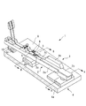
以下、図面を参照しながら、本発明の好ましい実施形態について詳細に説明する。図1は、本発明の実施形態によるグランドピアノの鍵盤を部分的に示している。同図に示すように、この鍵盤は、複数の鍵1(白鍵2および黒鍵3、それぞれ1つのみ図示)と、これらの鍵1を支持する筬4などを備えている。以下の説明では、演奏者側から見たときのピアノの手前側を「前」、奥側を「後」として説明する。
Hereinafter, preferred embodiments of the present invention will be described in detail with reference to the drawings. FIG. 1 partially shows a keyboard of a grand piano according to an embodiment of the present invention. As shown in the figure, the keyboard includes a plurality of keys 1 (a
白鍵2は、前後方向に延びる鍵本体2aと、その前部の上面から前面にわたって貼り付けられた白鍵カバー2bなどで構成されている。白鍵カバー2bは、側面形状がL字状の合成樹脂製の薄い板で構成されている。また、鍵本体2aは、例えばスプルスなどの木質材で構成され、矩形の断面を有し、前端部の幅は、その後ろ側の部分よりも広くなっている。鍵本体2aの上面中央には中座板5が貼り付けられている。
The
白鍵2の中央には、鍵本体2aから中座板5にわたって、上下方向に貫通するバランスピン孔2dが形成されている。図2に示すように、バランスピン孔2dは、下端部が丸孔で構成され、その上側の部分は、下端部の前後両側に延びている。また、このバランスピン孔2dには、その左右の壁面から中座板5の上面まで、左右一対のブッシングクロス6、6が貼り付けられている。これらのブッシングクロス6、6は、羊毛製のクロスで構成されている。
In the center of the
また、図3に示すように、鍵本体2aの前端部の下面には、フロントピン穴2eが形成されている。このフロントピン穴2eは、鍵本体2aの下面に開口し、鍵本体2aの上面付近まで延びるとともに、前後方向に延びている。また、フロントピン穴2eには、その左右の壁面から鍵本体2aの下面まで、左右一対のブッシングクロス7、7が貼り付けられている。これらのブッシングクロス7、7もまた、羊毛製のクロスで構成されている。
As shown in FIG. 3, a
黒鍵3は、白鍵2の鍵本体2aよりも短い鍵本体3aと、その前部に貼り付けられた黒鍵カバー3bなどを備えている。白鍵2および黒鍵3は、互いにほぼ同じ構成を有するので、同様の構成については説明を省略する。
The black key 3 includes a
筬4は、棚板8に載置されており、前側から順に互いに間隔を隔てて設けられた筬前4a、筬中4bおよび筬後4cで構成されており、これらは左右方向に延びている。
The saddle 4 is placed on the
筬中4bには、多数のバランスピン9が白鍵2および黒鍵3ごとに立設されている。このバランスピン9は、例えば真ちゅうで構成され、その表面にニッケルのめっきが施されており、筬中4bに打ち込みによって取り付けられる。また、バランスピン9には、リング状のバランスパンチングクロス12が通されており、このバランスパンチングクロス12は、筬中4bに載せられている。
A large number of
白鍵2は、そのバランスピン孔2dを介してバランスピン9に係合しており、それにより、バランスピン9を中心として、筬中4bに揺動自在に支持されている。
The
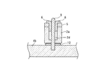
筬前4aには、多数のフロントピン10が白鍵2および黒鍵3ごとに立設されている。図4に示すように、フロントピン10の基端部は、その表面にローレット加工を施したローレット部10bになっている。フロントピン10は、このローレット部10bの部分を筬前4aに打ち込むことによって、筬前4aに取り付けられている
A large number of
フロントピン10は、例えば真ちゅうで構成され、図5に示すように、その表面には、コーティング層10aが形成されている。このコーティング層10aは、例えば、PTFE(ポリテトラフルオロエチレン(4フッ化))などのフッ素樹脂を含むニッケルで構成されており、このため、表面が硬く、滑り性および耐摩耗性に優れている。コーティング層10aは、例えば、フロントピン10を所定量のフッ素樹脂を添加したニッケルのめっき液に、ローレット部10bを形成したフロントピン10全体を浸漬することによって形成される。
The
また、フロントピン10には、リング状のフロントパンチングクロス11が通されており、このフロントパンチングクロス11は、筬前4aに載せられている。
Further, a ring-shaped
以上の構成のフロントピン10に、白鍵2がフロントピン穴2eを介して係合しており、それにより、フロントピン10による案内によって、白鍵2の左右方向のぶれが規制される。
The
筬後4cの上面には、クロスなどで構成された鍵盤枕13が貼り付けられている。離鍵状態では、鍵本体2aの後端部が、鍵盤枕13に着座している。
A
以上の構成により、白鍵2が押鍵されると、白鍵2は、バランスピン9を中心として揺動する。この白鍵2の揺動の際、バランスピン孔2dに設けられたブッシングクロス6がバランスピン9に沿って摺動し、また、フロントピン穴2eに設けられたブッシングクロス7がフロントピン10に沿って摺動する。
With the above configuration, when the
本実施形態によれば、フロントピン10にフッ素樹脂を含むコーティング層10aが形成されているので、ブッシングクロス7とフロントピン10との間で発生する摩擦を低減することができる。それにより、フロントピン10の傷付きや、ブッシングクロス7の摩耗および焼き付きが生じにくくなり、その結果、ブッシングクロス7とフロントピン10との摩擦を小さい状態に長時間、維持できる。これにより、潤滑剤の塗布や頻繁なメンテナンスを必要とすることなく、フロントピン10の滑り性を長期間、維持することができる。
According to the present embodiment, since the
また、フロントピン10は、そのローレット部10bを筬前4aに打ち込むことによって、筬前4aに取り付けられているので、ローレット部10bによって、フロントピン10の保持力が高められる。したがって、フロントピン10にフッ素樹脂を含むコーティング層10aが形成されることによるフロントピン10の保持力の低下分を、ローレット部10bによる保持力で補うことができる。その結果、フロントピン10の保持力が保たれることによって、フロントピン10のぐらつきや筬前4aからの離脱などを防止することができる。
Moreover, since the
なお、本発明は、上述した実施形態に限定されることなく、種々の態様で実施することができる。例えば、実施形態のコーティング層10aをバランスピン9の表面に形成することによって、ブッシングクロス6とバランスピン9との間で発生する摩擦を低減するように構成してもよい。また、実施形態では、フロントピン10の表面の凹凸をローレット加工によって形成しているが、他の形成方法を採用してもよいことはもちろんである。その他、細部の構成を、本発明の趣旨の範囲内で適宜、変更することが可能である。
In addition, this invention can be implemented in various aspects, without being limited to the embodiment described above. For example, the
1 鍵(鍵支持装置)
2 白鍵(鍵)
2d、3c バランスピン孔(係合孔)
2e フロントピン穴(係合孔)
3 黒鍵(鍵)
4 筬
6、7 ブッシングクロス
8 棚板
9 バランスピン(鍵盤ピン)
10 フロントピン(鍵盤ピン)
10a コーティング層
10b ローレット部(凹凸)
1 key (key support device)
2 White key (key)
2d, 3c Balance pin hole (engagement hole)
2e Front pin hole (engagement hole)
3 Black key
4 筬 6, 7
10 Front pin (keyboard pin)
Claims (3)
棚板の上面に載置された筬と、
当該筬に立設され、前記鍵が前記係合孔を介して係合するとともに、押鍵に伴って前記鍵が揺動する際に、前記ブッシングクロスが摺動する鍵盤ピンと、を備え、
当該鍵盤ピンの表面に、フッ素樹脂を含むコーティング層が形成されていることを特徴とするピアノの鍵支持装置。 A piano key support device that has an engagement hole that extends in the front-rear direction and opens on the lower surface, and supports a key having a bushing cross attached to the wall surface of the engagement hole in a swingable manner.
A bowl placed on the top surface of the shelf,
A keyboard pin that is erected on the hook and that engages the key through the engagement hole, and that the bushing cross slides when the key swings as the key is pressed;
A piano key support device, wherein a coating layer containing a fluororesin is formed on a surface of the keyboard pin.
前記鍵盤ピンは、前記フロントピン穴が係合し、前記鍵を左右方向にぶれないように案内するためのフロントピンであることを特徴とする請求項1に記載のピアノの鍵支持装置。 The engagement hole is a front pin hole formed at the front end of the key,
2. The piano key support device according to claim 1, wherein the keyboard pin is a front pin for guiding the key so that the front pin hole is engaged and the key is not moved in the left-right direction.
Priority Applications (1)
| Application Number | Priority Date | Filing Date | Title |
|---|---|---|---|
| JP2008163500A JP5210725B2 (en) | 2008-06-23 | 2008-06-23 | Piano key support device |
Applications Claiming Priority (1)
| Application Number | Priority Date | Filing Date | Title |
|---|---|---|---|
| JP2008163500A JP5210725B2 (en) | 2008-06-23 | 2008-06-23 | Piano key support device |
Publications (2)
| Publication Number | Publication Date |
|---|---|
| JP2010002848A true JP2010002848A (en) | 2010-01-07 |
| JP5210725B2 JP5210725B2 (en) | 2013-06-12 |
Family
ID=41584604
Family Applications (1)
| Application Number | Title | Priority Date | Filing Date |
|---|---|---|---|
| JP2008163500A Active JP5210725B2 (en) | 2008-06-23 | 2008-06-23 | Piano key support device |
Country Status (1)
| Country | Link |
|---|---|
| JP (1) | JP5210725B2 (en) |
Citations (5)
| Publication number | Priority date | Publication date | Assignee | Title |
|---|---|---|---|---|
| JPS5466837U (en) * | 1977-10-20 | 1979-05-12 | ||
| JPS6030489U (en) * | 1983-08-06 | 1985-03-01 | ヤマハ株式会社 | Piano action bearing bush |
| JPH05143061A (en) * | 1991-11-21 | 1993-06-11 | Yamaha Corp | Keyboard device |
| JPH08328547A (en) * | 1995-06-02 | 1996-12-13 | Kawai Musical Instr Mfg Co Ltd | Capstan screw of piano |
| JPH09258720A (en) * | 1996-03-22 | 1997-10-03 | Kawai Musical Instr Mfg Co Ltd | Keyboard for musical instrument |
-
2008
- 2008-06-23 JP JP2008163500A patent/JP5210725B2/en active Active
Patent Citations (5)
| Publication number | Priority date | Publication date | Assignee | Title |
|---|---|---|---|---|
| JPS5466837U (en) * | 1977-10-20 | 1979-05-12 | ||
| JPS6030489U (en) * | 1983-08-06 | 1985-03-01 | ヤマハ株式会社 | Piano action bearing bush |
| JPH05143061A (en) * | 1991-11-21 | 1993-06-11 | Yamaha Corp | Keyboard device |
| JPH08328547A (en) * | 1995-06-02 | 1996-12-13 | Kawai Musical Instr Mfg Co Ltd | Capstan screw of piano |
| JPH09258720A (en) * | 1996-03-22 | 1997-10-03 | Kawai Musical Instr Mfg Co Ltd | Keyboard for musical instrument |
Also Published As
| Publication number | Publication date |
|---|---|
| JP5210725B2 (en) | 2013-06-12 |
Similar Documents
| Publication | Publication Date | Title |
|---|---|---|
| JP5228743B2 (en) | Keyboard device | |
| US9940916B2 (en) | Key guide structure for keyboard instrument | |
| JP2007264057A (en) | Key guide device of keyboard instrument | |
| JP4549090B2 (en) | Rotating parts of keyboard instruments and key support mechanism | |
| JP5210725B2 (en) | Piano key support device | |
| US7807912B2 (en) | Key for keyboard instrument | |
| JP6323700B1 (en) | Keyboard instrument | |
| JP4438410B2 (en) | Key guide structure of keyboard device | |
| JP5662851B2 (en) | Keyboard device for keyboard instrument | |
| JP4853766B2 (en) | Electronic keyboard instrument key guide structure | |
| JP6311905B1 (en) | Keyboard instrument | |
| JP2010116728A (en) | Top-railed sliding door device | |
| JP6143620B2 (en) | Keyboard device | |
| JP6196876B2 (en) | Key guide structure of keyboard instrument | |
| JP2014235349A (en) | Keyboard structure and training tool of keyboard instrument or electronic keyboard instrument using the same | |
| JP2008020773A (en) | Keyboard device of keyboard instrument | |
| JP5233117B2 (en) | Keyboard device | |
| JP6597816B2 (en) | Keyboard instrument | |
| JP2008129309A (en) | Hammer device of grand piano | |
| JP2024051210A (en) | Keyboard device for keyboard instruments | |
| JP2024051204A (en) | Key guide structure for keyboard instruments | |
| JP5131465B2 (en) | Electronic musical instrument keyboard device | |
| JPH06175648A (en) | Keyboard device | |
| JP2000125961A (en) | Tray drawing device | |
| JP2020190758A (en) | Keyboard instrument |
Legal Events
| Date | Code | Title | Description |
|---|---|---|---|
| A621 | Written request for application examination |
Free format text: JAPANESE INTERMEDIATE CODE: A621 Effective date: 20110420 |
|
| A977 | Report on retrieval |
Free format text: JAPANESE INTERMEDIATE CODE: A971007 Effective date: 20121017 |
|
| A131 | Notification of reasons for refusal |
Free format text: JAPANESE INTERMEDIATE CODE: A131 Effective date: 20121113 |
|
| A521 | Written amendment |
Free format text: JAPANESE INTERMEDIATE CODE: A523 Effective date: 20121220 |
|
| TRDD | Decision of grant or rejection written | ||
| A01 | Written decision to grant a patent or to grant a registration (utility model) |
Free format text: JAPANESE INTERMEDIATE CODE: A01 Effective date: 20130129 |
|
| A61 | First payment of annual fees (during grant procedure) |
Free format text: JAPANESE INTERMEDIATE CODE: A61 Effective date: 20130225 |
|
| FPAY | Renewal fee payment (event date is renewal date of database) |
Free format text: PAYMENT UNTIL: 20160301 Year of fee payment: 3 |
|
| R150 | Certificate of patent or registration of utility model |
Ref document number: 5210725 Country of ref document: JP Free format text: JAPANESE INTERMEDIATE CODE: R150 Free format text: JAPANESE INTERMEDIATE CODE: R150 |