JP2010002722A - Camera module and manufacturing method thereof - Google Patents

Camera module and manufacturing method thereof Download PDF

Info

Publication number
JP2010002722A
JP2010002722A JP2008161864A JP2008161864A JP2010002722A JP 2010002722 A JP2010002722 A JP 2010002722A JP 2008161864 A JP2008161864 A JP 2008161864A JP 2008161864 A JP2008161864 A JP 2008161864A JP 2010002722 A JP2010002722 A JP 2010002722A
Authority
JP
Japan
Prior art keywords
lens barrel
spring
optical system
barrel
camera module
Prior art date
Legal status (The legal status is an assumption and is not a legal conclusion. Google has not performed a legal analysis and makes no representation as to the accuracy of the status listed.)
Granted
Application number
JP2008161864A
Other languages
Japanese (ja)
Other versions
JP2010002722A5 (en
JP5125799B2 (en
Inventor
Kazuhiko Takatsuka
和彦 高塚
Hiroaki Tojo
宏昭 東條
Masashi Nishimoto
雅志 西本
Satoshi Imai
聡 今井
Current Assignee (The listed assignees may be inaccurate. Google has not performed a legal analysis and makes no representation or warranty as to the accuracy of the list.)
Sony Corp
Original Assignee
Sony Corp
Priority date (The priority date is an assumption and is not a legal conclusion. Google has not performed a legal analysis and makes no representation as to the accuracy of the date listed.)
Filing date
Publication date
Application filed by Sony Corp filed Critical Sony Corp
Priority to JP2008161864A priority Critical patent/JP5125799B2/en
Publication of JP2010002722A publication Critical patent/JP2010002722A/en
Publication of JP2010002722A5 publication Critical patent/JP2010002722A5/ja
Application granted granted Critical
Publication of JP5125799B2 publication Critical patent/JP5125799B2/en
Expired - Fee Related legal-status Critical Current
Anticipated expiration legal-status Critical

Links

Images

Abstract

<P>PROBLEM TO BE SOLVED: To provide a camera module advantageous in size reduction, and to provide a manufacturing method thereof. <P>SOLUTION: The external faces of the portions of the rear and front lens barrels 24 and 22 sandwiching the lengthwise end of a rear spring 34 have recesses 82 receding from the external faces 25 in the peripheral parts of the sandwiching portions. The lengthwise end of the rear spring 34 is located in a part displaced inside from the imaginary extension planes of the external faces 25 in the peripheral parts. The rear lens barrel 24 has a rear end face 2402 located opposite the front lens barrel 22. The recesses 82 are formed in the rear end face 2402 so as to be open. The bottom 8202 of the recess 82 formed in the rear lens barrel 24 is formed from an inclining face that gradually increases the depth of the recess 82 toward the rear end face 2402. <P>COPYRIGHT: (C)2010,JPO&INPIT

Description

本発明は例えば携帯用の電子機器などに組み込まれるカメラモジュールおよびその製造方法に関する。   The present invention relates to a camera module incorporated in, for example, a portable electronic device and a manufacturing method thereof.

近年、カメラモジュールが組み込まれた携帯電話機、あるいはPDA(Personal Digital Assistants)などの電子機器が提供されている。
このようなカメラモジュールとして、後鏡筒と、前鏡筒と、撮像光学系を保持するレンズ保持部材と、撮像光学系によって導かれた被写体像を撮像する撮像素子と、レンズ保持部を撮像光学系の光軸に沿って移動可能に支持する案内機構と、レンズ保持部を前記撮像光学系の光軸に沿って移動させる駆動部とを備えるものが提供されている(特許文献1参照)。
このカメラモジュールでは、前記案内機構は、レンズ保持部を撮像素子側から撮影光学系側に付勢する後スプリングと、レンズ保持部を撮影光学系側から撮像素子側に付勢する前スプリングとを有している。
そして、後スプリングの延在方向の端部は、前鏡筒と後鏡筒とで挟持されて配設されている。
後スプリングの組み付けは次のようになされる。
すなわち、後スプリングと、この後スプリングの外周に枠状に延在する枠部と、枠部と後スプリングとを接続する接続部とを含むスプリング部材をプレス加工により形成しておく。
次いで、スプリング部材を前鏡筒と後鏡筒とで挟持し、前鏡筒と後鏡筒の外方に位置する接続部の部分をレーザー光線によって切断し、スプリング部材から後スプリングを切り離す。
特開2006−227100
2. Description of the Related Art In recent years, mobile phones incorporating camera modules or electronic devices such as PDAs (Personal Digital Assistants) have been provided.
As such a camera module, a rear lens barrel, a front lens barrel, a lens holding member for holding an imaging optical system, an imaging device for imaging a subject image guided by the imaging optical system, and a lens holding unit for imaging optics There is provided an apparatus including a guide mechanism that supports a system so as to be movable along the optical axis of the system, and a drive unit that moves a lens holding unit along the optical axis of the imaging optical system (see Patent Document 1).
In this camera module, the guide mechanism includes a rear spring that biases the lens holding portion from the imaging element side to the photographing optical system side, and a front spring that biases the lens holding portion from the photographing optical system side to the imaging element side. Have.
The end portion of the rear spring in the extending direction is disposed so as to be sandwiched between the front lens barrel and the rear lens barrel.
The rear spring is assembled as follows.
That is, a spring member including a rear spring, a frame portion extending in a frame shape on the outer periphery of the rear spring, and a connection portion connecting the frame portion and the rear spring is formed by press working.
Next, the spring member is sandwiched between the front lens barrel and the rear lens barrel, the portion of the connecting portion located outside the front lens barrel and the rear lens barrel is cut with a laser beam, and the rear spring is separated from the spring member.
JP 2006-227100 A

しかしながら、上記従来のカメラモジュールでは、レーザー光線による接続部の切断に際して、レーザー光線による前鏡筒と後鏡筒への加熱によるダメージを防止するために、接続部の切断箇所と、前鏡筒および後鏡筒との間隔を確保する必要がある。
そのため、接続部の切断箇所が前鏡筒および後鏡筒の輪郭から突出するため、カメラモジュールの小型化を図り難い不利がある。
本発明はこのような事情に鑑みなされたものであり、本発明の目的は、小型化を図る上で有利なカメラモジュールおよびその製造方法を提供することにある。
However, in the above-described conventional camera module, in order to prevent damage to the front lens barrel and the rear lens barrel due to heating by the laser beam when the connection portion is cut by the laser beam, the connection portion is cut, the front lens barrel, and the rear mirror. It is necessary to secure a distance from the cylinder.
For this reason, there is a disadvantage that it is difficult to reduce the size of the camera module because the cut portion of the connecting portion protrudes from the contours of the front and rear lens barrels.
The present invention has been made in view of such circumstances, and an object of the present invention is to provide a camera module and a method for manufacturing the same that are advantageous in reducing the size.

上述の目的を達成するため、本発明のカメラモジュールは、後鏡筒と、前記後鏡筒に組みつけられ前記後鏡筒と共に収容空間を形成する前鏡筒と、撮像光学系を保持し前記収容空間に収容されたレンズ保持部と、前記後鏡筒に支持され前記撮影光学系で導かれた被写体像を撮像する撮像素子と、前記レンズ保持部を前記撮像光学系の光軸に沿って移動可能に支持する案内機構と、前記レンズ保持部を前記撮像光学系の光軸に沿って移動させる駆動部とを備え、前記案内機構は、前記レンズ保持部を前記撮像素子側から前記撮影光学系側に付勢する後スプリングと、前記レンズ保持部を前記撮影光学系側から前記撮像素子側に付勢する前スプリングとを有し、前記後スプリングと前記前スプリングは、ばね板が帯状に延在して構成され、前記後スプリングと前記前スプリングの少なくとも一方のスプリングの延在方向の端部は、前記前鏡筒と前記後鏡筒とで挟持されて配設され、前記スプリングの延在方向の端部を挟持する前記後鏡筒の部分と前記前鏡筒の部分の外面は、それら挟持する部分の周囲の箇所の外面よりも窪んで凹部を形成しており、前記スプリングの延在方向の端部は、前記凹部内に位置し、かつ、前記周囲の箇所の外面の仮想延長面よりも内側に偏位した箇所に位置している。
また本発明のカメラモジュールの製造方法は、後鏡筒と、前記後鏡筒に組み付けられ前記後鏡筒と共に収容空間を形成する前鏡筒と、撮像光学系を保持し前記収容空間に収容されたレンズ保持部と、前記レンズ保持部を前記撮像光学系の光軸に沿って移動可能に支持する案内機構とを備え、前記案内機構は、前記レンズ保持部を前記撮像素子側から前記撮影光学系側に付勢する後スプリングと、前記レンズ保持部を前記撮影光学系側から前記撮像素子側に付勢する前スプリングとを有し、前記後鏡筒は、前記前鏡筒と反対に位置する後端面を有し、前記前鏡筒は、前記後鏡筒と反対に位置する前端面を有するカメラモジュールの製造方法であって、前記後スプリングと前記前スプリングのうちの一方のスプリングを、ばね板製の板材をプレス加工することで矩形枠と一体にこの矩形枠の内側に帯状に延在して形成し、前記矩形枠寄りに位置する前記スプリングの延在方向の端部を、前記前鏡筒と前記後鏡筒とで挟持し、前記挟持する前記後鏡筒の部分と前記前鏡筒の部分の外面を、それら挟持する部分の周囲の箇所の外面よりも窪んだ凹部に形成しておき、レーザーを前記凹部内に照射して前記スプリングと前記矩形枠とを切り離すようにした。
In order to achieve the above-described object, a camera module of the present invention includes a rear lens barrel, a front lens barrel that is assembled to the rear lens barrel and forms an accommodation space with the rear lens barrel, and an imaging optical system. A lens holding part housed in the housing space, an image pickup device for picking up a subject image supported by the rear lens barrel and guided by the photographing optical system, and the lens holding part along the optical axis of the imaging optical system A guide mechanism that movably supports the driving mechanism that moves the lens holding unit along the optical axis of the imaging optical system; and the guide mechanism moves the lens holding unit from the imaging element side to the imaging optical system. A rear spring that biases toward the system side, and a front spring that biases the lens holding portion from the imaging optical system side toward the imaging element side, and the rear spring and the front spring have a spring plate in a band shape After extending, said after An end portion in the extending direction of at least one of the pulling and the front spring is disposed to be sandwiched between the front lens barrel and the rear lens barrel, and sandwiches an end portion in the extending direction of the spring. The outer surface of the rear lens barrel portion and the front lens barrel portion are recessed from the outer surface of the portion around the sandwiched portion to form a recess, and the end in the extending direction of the spring is the recess It is located in and the location which deviated inward rather than the virtual extension surface of the outer surface of the said surrounding location.
The camera module manufacturing method according to the present invention includes a rear lens barrel, a front lens barrel that is assembled to the rear lens barrel and forms an accommodation space together with the rear lens barrel, and an imaging optical system that is accommodated in the accommodation space. A lens holding portion and a guide mechanism that supports the lens holding portion so as to be movable along the optical axis of the imaging optical system. A rear spring that biases toward the system side, and a front spring that biases the lens holding portion from the imaging optical system side toward the imaging element side, and the rear lens barrel is positioned opposite to the front lens barrel The front lens barrel is a method for manufacturing a camera module having a front end surface positioned opposite to the rear lens barrel, wherein one of the rear spring and the front spring is provided. Press spring plate material The end of the extension direction of the spring located near the rectangular frame is formed in the rectangular frame integrally with the rectangular frame. The outer surface of the rear lens barrel portion and the front lens barrel portion to be sandwiched are formed in a recessed portion that is recessed from the outer surface of the portion around the sandwiched portion, and the laser is The spring and the rectangular frame were separated by irradiating in the recess.

本発明によれば、スプリングの延在方向の端部を挟持する後鏡筒の部分と前鏡筒の部分の外面は、それら挟持する部分の周囲の箇所の外面よりも窪んで凹部を形成している。また、スプリングの延在方向の端部は、凹部内に位置し、かつ、周囲の箇所の外面の仮想延長面よりも内側に偏位した箇所に位置している。
そのため、スプリングの延在方向の端部が凹部内に位置して前鏡筒および後鏡筒の輪郭の内側に留まっている。
したがって、カメラモジュールの外形寸法の小型化を図る上で有利となる。
According to the present invention, the outer surface of the rear lens barrel portion and the outer surface of the front lens barrel portion that sandwich the end portion in the extending direction of the spring are recessed from the outer surface of the portion around the sandwiched portion to form a recess. ing. Moreover, the edge part of the extension direction of a spring is located in the recessed part, and is located in the location displaced inside the virtual extension surface of the outer surface of the surrounding location.
For this reason, the end portion in the extending direction of the spring is located in the recess and remains inside the contours of the front lens barrel and the rear lens barrel.
Therefore, it is advantageous in reducing the external dimensions of the camera module.

次に本発明の実施の形態について図面を参照して説明する。
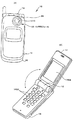
図1(A)、(B)は本実施の形態に係るカメラモジュール20が組み込まれた電子機器の一例を示す外観図である。
図1に示すように電子機器10は携帯電話機であり、ヒンジ部12によって揺動可能に連結された第1、第2の筐体14、16を有している。
第1の筐体14の内面には液晶表示パネル1402が設けられ、第2の筐体16の内面にはテンキーや機能キーなどの操作スイッチ1602が設けられている。
第1の筐体14にカメラモジュール20が設けられ、カメラモジュール20で撮像した画像は液晶表示パネル1402に表示される。
カメラモジュール20は被写体像を捉える撮像光学系28を有し、撮像光学系28は、第1の筐体14に設けられた開口1410に臨んでいる。
Next, embodiments of the present invention will be described with reference to the drawings.
1A and 1B are external views illustrating an example of an electronic device in which the camera module 20 according to this embodiment is incorporated.
As shown in FIG. 1, the electronic device 10 is a mobile phone, and includes first and second housings 14 and 16 that are swingably connected by a hinge portion 12.
A liquid crystal display panel 1402 is provided on the inner surface of the first housing 14, and operation switches 1602 such as numeric keys and function keys are provided on the inner surface of the second housing 16.
A camera module 20 is provided in the first housing 14, and an image captured by the camera module 20 is displayed on the liquid crystal display panel 1402.
The camera module 20 has an imaging optical system 28 that captures a subject image, and the imaging optical system 28 faces an opening 1410 provided in the first housing 14.

次に、本発明に係るカメラモジュール20の構成について詳細に説明する。
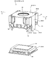
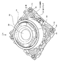
図2はカメラモジュール20の組み立て説明図、図3はカメラモジュール20の分解図、図4は図3のAA線断面図である。
また、本実施の形態では、被写体側を前方、その反対側を後方として説明する。
カメラモジュール20は、図2に示すように、上記の撮像光学系28に加えて、前鏡筒22と、後鏡筒24と、カバー26と、レンズ保持部材30と、前スプリング32と、後スプリング34と、撮像素子36と、駆動部38などを含んで構成されている。
Next, the configuration of the camera module 20 according to the present invention will be described in detail.
2 is an assembly explanatory view of the camera module 20, FIG. 3 is an exploded view of the camera module 20, and FIG. 4 is a sectional view taken along line AA in FIG.
In the present embodiment, the subject side will be described as the front and the opposite side as the rear.
As shown in FIG. 2, the camera module 20 includes a front lens barrel 22, a rear lens barrel 24, a cover 26, a lens holding member 30, a front spring 32, and a rear lens in addition to the imaging optical system 28 described above. A spring 34, an image sensor 36, a drive unit 38, and the like are included.

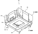
図5はカメラモジュール20を前方から見た斜視図、図6はカメラモジュール20を後方から見た斜視図、図7は図5のA矢視図、図8は図5のB矢視図、図9は図5のC矢視図、図10は図5のD矢視図、図11は図5のEE線断面図である。
なお、図5乃至図11は、カメラモジュール20から撮像素子36を除いた状態を示す。
図12は図5からカバー26を取り外した状態を前方から見た示す斜視図、図13は図12を後方から見た斜視図、図14は図12のA矢視図、図15は図12のB矢視図、図16は図12のC矢視図、図17は図12のD矢視図である。
図18は図12から前鏡筒22を取り外した状態を前方から見た示す斜視図、図19は図18を後方から見た斜視図、図20は図18のA矢視図、図21は図18のC矢視図、図22は図18のD矢視図である。
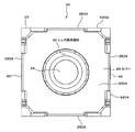
図23は図18からマグネット50を取り外した状態を前方から見た示す斜視図、図24は図23を後方から見た斜視図、図25は図23のA矢視図、図26は図23のC矢視図、図27は図23のD矢視図である。
図28はカバー26を前方から見た斜視図、図29はカバー26を後方から見た斜視図、図30は図28のA矢視図である。
5 is a perspective view of the camera module 20 as viewed from the front, FIG. 6 is a perspective view of the camera module 20 as viewed from the rear, FIG. 7 is a view as viewed from the arrow A in FIG. 5, and FIG. 9 is a view taken along the arrow C in FIG. 5, FIG. 10 is a view taken along the arrow D in FIG. 5, and FIG. 11 is a cross-sectional view taken along the line EE in FIG.
5 to 11 show the camera module 20 with the image sensor 36 removed.
12 is a perspective view showing the state in which the cover 26 is removed from FIG. 5 as viewed from the front, FIG. 13 is a perspective view of FIG. 12 as seen from the rear, FIG. 14 is a view as seen from the arrow A in FIG. FIG. 16 is a view taken in the direction of arrow C in FIG. 12, and FIG. 17 is a view taken in the direction of arrow D in FIG.
18 is a perspective view showing the state where the front lens barrel 22 is removed from FIG. 12, as seen from the front, FIG. 19 is a perspective view showing FIG. 18 from the rear, FIG. 20 is a view as seen from the arrow A in FIG. 18 is a view as viewed from an arrow C in FIG. 18, and FIG. 22 is a view as viewed from an arrow D in FIG.
23 is a perspective view showing the state where the magnet 50 is removed from FIG. 18 as viewed from the front, FIG. 24 is a perspective view when FIG. 23 is seen from the rear, FIG. 25 is a view as seen from the arrow A in FIG. FIG. 27 is a view taken in the direction of arrow C, and FIG. 27 is a view taken in the direction of arrow D in FIG.
28 is a perspective view of the cover 26 as viewed from the front, FIG. 29 is a perspective view of the cover 26 as viewed from the rear, and FIG. 30 is a view as viewed from the direction of arrow A in FIG.

(前鏡筒22)
前鏡筒22は、図11に示すように、後鏡筒24に組みつけられ後鏡筒24と共に収容空間Sを形成するものである。
前鏡筒22は合成樹脂材料を金型で成形することで形成されている。
図31はマグネット50が前鏡筒22の内側に挿入された状態を示す斜視図、図32は図31のA矢視図である。
図12、図31に示すように、前鏡筒22は、前枠40と、第1、第2、第3、第4側壁42A乃至42Dとを含んで構成されている。
前枠40は、平面視矩形枠状を呈し、互いに対向する2組の辺を有している。
第1、第2側壁42A、42Bは、前枠40の互いに対向する1組の辺から後方に突設され、第3、第4側壁42C、42Dは、前枠40の互いに対向する残りの1組の辺から後方に突設されている。
第1、第2、第3、第4側壁42A乃至42Dに、後方に開放状の矩形状の欠部43がそれぞれ形成されている。
図31に示すように、前枠40が4つの欠部43に臨む箇所には、撮像光学系28の光軸と直交する同一平面上を延在するマグネット当て付け用の当接面4002がそれぞれ形成されている。
第1、第2側壁42A、42Bの内面の両側には、図32に示すように、平面からなるマグネット位置決め面4202がそれぞれ形成され、合計4つのマグネット位置決め面4202が形成されている。
図12、図31に示すように、第1、第2、第3、第4側壁42A乃至42Dが後方に臨む後端面は、後鏡筒24への合わせ面4210として形成されている。
本実施の形態では、各側壁42A乃至42Dが欠部43で切り離されていることから、合わせ面4210は前枠40の4つの角部に対応した4箇所に形成されている。
4つの合わせ面4210には、図31に示すように、それぞれ後述する後鏡筒24のピン48(図18)の径と長さよりも大きな形状を有しピン48を収容する逃げ孔4212が後方に開放状に形成されている。
また、図31、図32に示すように、第1、第2側壁42A、42Bの両側箇所に、前後に延在する溝で形成された第1位置決め部4220がそれぞれ前後に開放状に形成されている。
また、欠部43に臨む第3、第4側壁42C、42Dの後部寄りの箇所に、互いに対向して前後に延在する平行な平面で形成された第2位置決め部4230がそれぞれ形成されている。
(Front barrel 22)
As shown in FIG. 11, the front lens barrel 22 is assembled to the rear lens barrel 24 and forms a housing space S together with the rear lens barrel 24.
The front lens barrel 22 is formed by molding a synthetic resin material with a mold.
FIG. 31 is a perspective view showing a state in which the magnet 50 is inserted inside the front barrel 22, and FIG. 32 is a view taken in the direction of arrow A in FIG.
As shown in FIGS. 12 and 31, the front lens barrel 22 includes a front frame 40 and first, second, third, and fourth side walls 42A to 42D.
The front frame 40 has a rectangular frame shape in plan view and has two sets of sides facing each other.
The first and second side walls 42A and 42B project rearward from a pair of opposite sides of the front frame 40, and the third and fourth side walls 42C and 42D are the remaining one of the front frame 40 facing each other. It protrudes backward from the side of the set.
The first, second, third, and fourth side walls 42A to 42D are respectively formed with open rectangular cutouts 43 on the rear side.
As shown in FIG. 31, at the positions where the front frame 40 faces the four cutouts 43, the magnet contact contact surfaces 4002 extending on the same plane orthogonal to the optical axis of the imaging optical system 28 are respectively provided. Is formed.
On both sides of the inner surfaces of the first and second side walls 42A and 42B, as shown in FIG. 32, a flat magnet positioning surface 4202 is formed, and a total of four magnet positioning surfaces 4202 are formed.
As shown in FIGS. 12 and 31, the rear end face where the first, second, third, and fourth side walls 42 </ b> A to 42 </ b> D face rearward is formed as a mating face 4210 for the rear barrel 24.
In the present embodiment, since the side walls 42A to 42D are separated by the notch 43, the mating surface 4210 is formed at four locations corresponding to the four corners of the front frame 40.
As shown in FIG. 31, the four mating surfaces 4210 have rear holes 4212 that have shapes larger than the diameter and length of the pins 48 (FIG. 18) of the rear barrel 24, which will be described later, and accommodate the pins 48. It is formed in an open shape.
Further, as shown in FIGS. 31 and 32, first positioning portions 4220 formed by grooves extending in the front-rear direction are formed in the front and rear sides at both side portions of the first and second side walls 42A, 42B. ing.
In addition, second positioning portions 4230 formed by parallel planes extending in the front-rear direction so as to face each other are formed at positions near the rear portions of the third and fourth side walls 42C and 42D facing the notch portion 43, respectively. .

(後鏡筒24)
後鏡筒24は、図2、図11、図13、図15に示すように、底壁44と、開口46とを有している。
底壁44は、収容空間Sの前記光軸方向の後端を閉塞する矩形板状に形成され、したがって、底壁44の前面は図11に示すように収容空間Sに臨んでいる。
底壁44は、図18、図20に示すように、互いに対向する2組の辺4402、4404を有している。
底壁44の前面で、前鏡筒22の合わせ面4210に対応した箇所は、合わせ面4410として形成され、図12に示すように、前鏡筒22の合わせ面4010と、後鏡筒24の合わせ面4210はそれぞれ重ね合わされる。
図18、図20に示すように、底壁44の前面の2組の辺のうち一方の組の辺4402には、前鏡筒22の第1位置決め部4220に係合する凸部で形成された第3位置決め部4420がそれぞれ設けられている。
底壁44の前面の2組の辺のうち他方の組の辺4404には、前鏡筒22の第2位置部4230に係合する面で形成された第4位置決め部4430がそれぞれ設けられている。
さらに、図18に示すように、底壁44の前面の各辺4402、4404の中間部には、マグネット50の後端面5010(図11)が載置される載置面4440が撮像光学系28の光軸と直交する方向に延在する同一平面上に延在するようにそれぞれ形成されている。
底壁44の前面の2組の辺のうち他方の組の辺4404には、後スプリング34を取り付けるための2つのピン48がそれぞれ突設されている。
開口46は、図11、図15に示すように、底壁44の中央に形成され、矩形状を呈している。
本実施の形態では、開口46は、撮像光学系28を介して撮像素子36に導かれる光線を制限する固定絞りとして機能している。
また、図18、図20に示すように、底壁44の2組の辺のうちの他方の組の辺の中央に、カバー26を取り付けるための係合突起60がそれぞれ突設されている。
なお、図11において符号4450は、後鏡筒24の底壁44の前面から前方に向かって膨出形成された隔壁を示し、本実施の形態では、隔壁4450は、開口46の周囲の全周にわたって環状に延在している。
この隔壁4450は、カメラモジュール20を撮像光学系28の光軸方向から見た状態で、後述する後スプリング34の接続片部7002(図33)とコイル52の巻線の両端5202とが半田付けされる半田付け箇所と、撮像光学系28のうち、最も後方に位置するレンズのレンズ面2802との間を仕切るように設けられている。
隔壁4450は、前記半田付け箇所から脱落したフラックスなどの塵埃がレンズ面2802に移動することを阻止するため、前記塵埃のレンズ面2802への付着が効果的に防止され、撮像素子36によって撮像される画像の品質の確保が図られている。
また、隔壁4450の外側で前記半田付け箇所に臨む底壁44の前面の箇所には、後方に窪む凹部4452がそれぞれ形成されている。
凹部4452は、前記半田付け箇所から脱落したフラックスなどの塵埃を収容するため、前記塵埃のレンズ面2802への付着がより効果的に防止され、撮像素子36によって撮像される画像の品質の確保がより一層図られている。
(Rear barrel 24)
As shown in FIGS. 2, 11, 13, and 15, the rear barrel 24 has a bottom wall 44 and an opening 46.
The bottom wall 44 is formed in a rectangular plate shape that closes the rear end in the optical axis direction of the accommodation space S. Therefore, the front surface of the bottom wall 44 faces the accommodation space S as shown in FIG.
As shown in FIGS. 18 and 20, the bottom wall 44 has two sets of sides 4402 and 4404 facing each other.
A portion of the front surface of the bottom wall 44 corresponding to the mating surface 4210 of the front barrel 22 is formed as a mating surface 4410. As shown in FIG. 12, the mating surface 4010 of the front barrel 22 and the rear barrel 24 The mating surfaces 4210 are overlaid.
As shown in FIGS. 18 and 20, one set of sides 4402 of the two sets of sides on the front surface of the bottom wall 44 is formed with a convex portion that engages with the first positioning portion 4220 of the front barrel 22. A third positioning portion 4420 is provided.
Of the two sets of sides of the front surface of the bottom wall 44, the other set of sides 4404 is provided with a fourth positioning portion 4430 formed by a surface that engages with the second position portion 4230 of the front barrel 22. Yes.
Further, as shown in FIG. 18, a mounting surface 4440 on which the rear end surface 5010 (FIG. 11) of the magnet 50 is mounted is provided at the middle portion of each side 4402, 4404 of the front surface of the bottom wall 44. Are formed so as to extend on the same plane extending in a direction orthogonal to the optical axis.
Two pins 48 for attaching the rear spring 34 project from the other side 4404 of the two sides of the front surface of the bottom wall 44.
As shown in FIGS. 11 and 15, the opening 46 is formed in the center of the bottom wall 44 and has a rectangular shape.
In the present embodiment, the opening 46 functions as a fixed diaphragm that restricts the light beam guided to the image sensor 36 via the imaging optical system 28.
Further, as shown in FIGS. 18 and 20, an engagement protrusion 60 for attaching the cover 26 protrudes from the center of the other set of two sides of the bottom wall 44.
In FIG. 11, reference numeral 4450 indicates a partition wall bulging forward from the front surface of the bottom wall 44 of the rear barrel 24, and in this embodiment, the partition wall 4450 is the entire circumference around the opening 46. It extends in a ring shape over.
The partition 4450 is soldered to a connecting piece 7002 (FIG. 33) of the later spring 34 and both ends 5202 of the coil 52, which will be described later, when the camera module 20 is viewed from the optical axis direction of the imaging optical system 28. It is provided so as to partition between the soldered portion to be performed and the lens surface 2802 of the lens located rearmost in the imaging optical system 28.
The partition wall 4450 prevents dust such as flux that has fallen off from the soldered portion from moving to the lens surface 2802, so that the dust is effectively prevented from adhering to the lens surface 2802 and is imaged by the image sensor 36. The quality of the image is ensured.
In addition, a recess 4452 that is recessed rearward is formed at a position on the front surface of the bottom wall 44 that faces the soldering position outside the partition wall 4450.
The concave portion 4452 accommodates dust such as flux that has fallen off from the soldered portion, so that the dust is more effectively prevented from adhering to the lens surface 2802, and the quality of the image captured by the image sensor 36 is ensured. It is even more planned.

(マグネット50)
駆動部38は、図11に示すように、マグネット50とコイル52を含んで構成されている。
マグネット50は、撮像光学系28の光軸を中心とする円周上に延在して設けられており、本実施の形態では、マグネット50は、図31、図32に示すように、同一形状の4つのマグネット分割体5002が円周方向に並べられることで構成されている。
マグネット50は、図11に示すように、コイル52の外周に臨んでおり、言い換えると、マグネット50はコイル52に対向して配置されている。
本実施の形態では、図11、図31、図32に示すように、各マグネット分割体5002は、それらマグネット分割体5002の磁束を効率よくコイル52に導くためのヨーク54に取着され、このヨーク54を介して前鏡筒24に取着されている。
したがって、マグネット50はヨーク54を含んで構成されている。
詳細には、ヨーク54は、図11に示すように、前方に位置する環板状の前壁部5402と、前面部5402の外周から後方に延在する円筒壁状の周壁部5404とを備えている。
各マグネット分割体5002は、周壁部5404の内周面に周方向に並べられて取着されている。
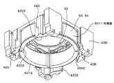
したがって、ヨーク54の前壁部5402によって、マグネット50の前端面5010が形成され、ヨーク54の周壁部5404の外周面によって、マグネット50の外周面5011が形成され、各マグネット分割体5002の後端面によってマグネット50の後端面5012が形成されている。
前端面5010および後端面5012は、撮像光学系28の光軸と直交する同一平面上を延在するように構成されている。
(Magnet 50)
As shown in FIG. 11, the drive unit 38 includes a magnet 50 and a coil 52.
The magnet 50 is provided so as to extend on the circumference centered on the optical axis of the imaging optical system 28. In the present embodiment, the magnet 50 has the same shape as shown in FIGS. The four magnet divided bodies 5002 are arranged in the circumferential direction.
As shown in FIG. 11, the magnet 50 faces the outer periphery of the coil 52, in other words, the magnet 50 is disposed to face the coil 52.
In this embodiment, as shown in FIGS. 11, 31, and 32, each magnet divided body 5002 is attached to a yoke 54 for efficiently guiding the magnetic flux of the magnet divided body 5002 to the coil 52. It is attached to the front lens barrel 24 via a yoke 54.
Therefore, the magnet 50 includes the yoke 54.
In detail, as shown in FIG. 11, the yoke 54 includes an annular plate-shaped front wall portion 5402 positioned in the front, and a cylindrical wall-shaped peripheral wall portion 5404 extending rearward from the outer periphery of the front surface portion 5402. ing.
The magnet divided bodies 5002 are attached to the inner peripheral surface of the peripheral wall portion 5404 in the circumferential direction.
Therefore, a front end surface 5010 of the magnet 50 is formed by the front wall portion 5402 of the yoke 54, and an outer peripheral surface 5011 of the magnet 50 is formed by the outer peripheral surface of the peripheral wall portion 5404 of the yoke 54. Thus, a rear end surface 5012 of the magnet 50 is formed.
The front end surface 5010 and the rear end surface 5012 are configured to extend on the same plane orthogonal to the optical axis of the imaging optical system 28.

(コイル52)
コイル52は、図18、図20に示すように、巻線が撮像光学系28の光軸を中心とする円周上に巻回されて形成され、その外径は、マグネット50の内径よりも小さい寸法で形成されている。
コイル52の後端面には、図2、図23に示すように、平面視した場合、コイル52と略同じ輪郭を有し、かつ、光軸方向の寸法がコイル52よりも小さい寸法で形成された環状のコイルホルダ56が取着されている。
コイルホルダ56は、図23、図25に示すように、180度位相を異ならせた対向する2箇所に軸部5602が半径方向外方に突設され、各軸部5602にコイル52の巻線の両端5202がそれぞれ巻回されている。
図33は、レンズ保持部材30、後スプリング34、コイル52、コイルホルダ56を示す斜視図である。
図33に示すように、コイルホルダ56の内周でコイルホルダ56の周方向に間隔をおいた複数箇所に取り付け部5610が突設されている。
また、コイルホルダ56の後面には、コイルホルダ56の周方向に間隔をおいた複数箇所にストッパ5620が突設されている。
各ストッパ5620は、図11に示すように、後鏡筒24の底壁44の前面の箇所に当接することで、レンズ保持部材30(撮像光学系28)の光軸方向の後方限界位置(無限遠方位置)を決定するものである。
(Coil 52)
As shown in FIGS. 18 and 20, the coil 52 is formed by winding a winding around a circumference around the optical axis of the imaging optical system 28, and the outer diameter thereof is larger than the inner diameter of the magnet 50. It is formed with small dimensions.
As shown in FIGS. 2 and 23, the coil 52 has a substantially same outline as the coil 52 and has a smaller dimension in the optical axis direction than the coil 52 when viewed in plan. An annular coil holder 56 is attached.
As shown in FIG. 23 and FIG. 25, the coil holder 56 has shaft portions 5602 protruding radially outward at two opposing positions with different phases by 180 degrees, and windings of the coils 52 are provided on the respective shaft portions 5602. Both ends 5202 are wound.
FIG. 33 is a perspective view showing the lens holding member 30, the rear spring 34, the coil 52, and the coil holder 56.
As shown in FIG. 33, attachment portions 5610 are projected from a plurality of locations at intervals in the circumferential direction of the coil holder 56 on the inner periphery of the coil holder 56.
In addition, stoppers 5620 protrude from the rear surface of the coil holder 56 at a plurality of positions spaced in the circumferential direction of the coil holder 56.
As shown in FIG. 11, each stopper 5620 abuts on a position on the front surface of the bottom wall 44 of the rear barrel 24, so that a rear limit position (infinite) in the optical axis direction of the lens holding member 30 (imaging optical system 28). Remote position).

(撮像素子36)
撮像素子36は、図4に示すように、パッケージ3602と、撮像素子チップ3604と、カバーガラス3604などを含んで構成されている。
パッケージ3602は、矩形板状を呈し、その前面に断面矩形状の収容空間が開放状に形成されている。
撮像素子チップ3604は、撮像光学系28によって導かれる被写体像を撮像するものであり、撮像面を前方に臨ませて前記収容空間の底壁に取着されている。
カバーガラス3604は、パッケージ3602の前面に取着され前記収容空間を封止するものである。
撮像素子36は、図3、図4に示すように、パッケージ3602の後面が矩形板状の基板58の前面に取着されている。
後鏡筒24の開口46内に撮像素子チップ3604の撮像面を臨ませた状態で、パッケージ3602の前面が後鏡筒24の底壁44の後面に取着され、したがって、撮像素子36は後鏡筒24に設けられている。
(Image sensor 36)
As shown in FIG. 4, the image sensor 36 includes a package 3602, an image sensor chip 3604, a cover glass 3604, and the like.
The package 3602 has a rectangular plate shape, and an accommodation space having a rectangular cross section is formed on the front surface thereof.
The image pickup device chip 3604 picks up a subject image guided by the image pickup optical system 28, and is attached to the bottom wall of the housing space with the image pickup surface facing forward.
The cover glass 3604 is attached to the front surface of the package 3602 and seals the accommodation space.
As shown in FIGS. 3 and 4, the imaging element 36 has a rear surface of a package 3602 attached to a front surface of a rectangular plate-like substrate 58.
The front surface of the
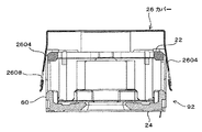
 package 3602 is attached to the rear surface of the bottom wall 44 of the rear lens barrel 24 with the image pickup surface of the image pickup device chip 3604 facing the opening 46 of the rear lens barrel 24. A lens barrel 24 is provided.

(カバー26)
カバー26は板金製であり、図28、図29、図30に示すように、前面部2602と、側面部2604とを備えている。
前面部2602は矩形板状を呈し、前鏡筒22の前面を覆うものである。
前面部2602が撮像光学系28に臨む箇所に開口2606が形成されている。
側面部2604は前面部2602の4辺からそれぞれ屈曲形成され、前鏡筒22および後鏡筒24の4つの側部を覆うものである。
4つの側面部2604のうち対向する1組の側面部2604には、図5に示す後鏡筒24の各係合突起60に係合する係合溝2608が設けられている。
カバー26の各係合溝2608が各係合突起60に係合することで、図11に示すように、カバー26の前面部2602と後鏡筒24の底壁44との間に前鏡筒22が挟持され、これにより前鏡筒22と後鏡筒24とが結合されている。
また、前面部2602が前方に臨む前面と、この前面から各側面部2604が外方に臨む外面のうち前面部2602寄りの部分は、光の反射を防止する反射防止部2610が形成されている。
反射防止部2610は、例えば、光の反射を防止する塗料が塗装されることで構成され、前記塗料は例えば黒色の塗料など光の反射を防止できるものであればよい。
(Cover 26)
The cover 26 is made of sheet metal and includes a front surface portion 2602 and a side surface portion 2604 as shown in FIGS. 28, 29, and 30.
The front surface portion 2602 has a rectangular plate shape and covers the front surface of the front lens barrel 22.
An opening 2606 is formed at a location where the front surface portion 2602 faces the imaging optical system 28.
The side surface portions 2604 are bent from the four sides of the front surface portion 2602, and cover the four side portions of the front lens barrel 22 and the rear lens barrel 24.
Engaging grooves 2608 that engage with the respective engaging protrusions 60 of the rear barrel 24 shown in FIG. 5 are provided in a pair of opposing side surface portions 2604 of the four side surface portions 2604.
The engagement grooves 2608 of the cover 26 engage with the engagement protrusions 60, so that the front lens barrel is located between the front surface portion 2602 of the cover 26 and the bottom wall 44 of the rear lens barrel 24 as shown in FIG. Thus, the front lens barrel 22 and the rear lens barrel 24 are joined together.
Further, an antireflection portion 2610 for preventing light reflection is formed on the front surface where the front surface portion 2602 faces forward and the portion near the front surface portion 2602 of the outer surface where each side surface portion 2604 faces outward from the front surface. .
The antireflection portion 2610 is configured by, for example, coating with a paint that prevents light reflection, and the paint may be any material that can prevent light reflection, such as a black paint.

(レンズ保持部材30)
レンズ保持部材30は、図11に示すように、撮像光学系28を保持して収容空間Sに収容されている。
レンズ保持部材30は、図23、図25に示すように、筒部3002と、筒部3002の前部を接続する環状の前部3004とを有し、前部3004の中央には開口3006が設けられている。
撮像光学系28は複数のレンズ群などを含んで構成され、筒部3002の内部に収容され、開口3006から前方を臨んでいる。
(Lens holding member 30)
As shown in FIG. 11, the lens holding member 30 holds the imaging optical system 28 and is housed in the housing space S.
As shown in FIGS. 23 and 25, the lens holding member 30 includes a cylindrical portion 3002 and an annular front portion 3004 that connects the front portion of the cylindrical portion 3002, and an opening 3006 is formed at the center of the front portion 3004. Is provided.
The imaging optical system 28 includes a plurality of lens groups and the like, is accommodated inside the cylindrical portion 3002, and faces the front from the opening 3006.

前部3004には、筒部3002の外径よりも小さい外径の膨出壁部3008が形成され、この膨出壁部3008の周面は撮像光学系28の光軸を中心とする円周上を延在する円筒面3010を形成している。
円筒面3010の外周に、周方向に等間隔をおいた4箇所に膨出壁部3008よりも後方に位置するように4つの前側スプリング当接面3012が形成されており、これら前側スプリング当接面3012は前記光軸と直交する平面上を延在している。
図33に示すように、筒部3002の後端面3020は、コイルホルダ56の各取り付け部5610に当接可能に設けられている。
The front portion 3004 is formed with a bulging wall portion 3008 having an outer diameter smaller than the outer diameter of the cylindrical portion 3002, and the circumferential surface of the bulging wall portion 3008 is a circumference centered on the optical axis of the imaging optical system 28. A cylindrical surface 3010 extending upward is formed.
Four front spring contact surfaces 3012 are formed on the outer periphery of the cylindrical surface 3010 so as to be positioned rearward of the bulging wall portion 3008 at four positions spaced at equal intervals in the circumferential direction. The surface 3012 extends on a plane orthogonal to the optical axis.
As shown in FIG. 33, the rear end surface 3020 of the cylindrical portion 3002 is provided so as to be able to contact each attachment portion 5610 of the coil holder 56.

(前スプリング32)
前スプリング32、後スプリング34は、図11に示すように、収容空間Sに配設されレンズ保持部材30を撮像光学系28の前記光軸に沿って移動可能に支持する案内機構を構成している。
前スプリング32は前鏡筒22とレンズ保持部材30の間に配設され、後スプリング34は後鏡筒24とレンズ保持部材30の間に配設されるものである。
後スプリング34と前スプリング32は、導電性を有し厚さが薄く小さい幅のばね板が帯状に延在して形成されている。
(Front spring 32)
As shown in FIG. 11, the front spring 32 and the rear spring 34 constitute a guide mechanism that is disposed in the accommodation space S and supports the lens holding member 30 so as to be movable along the optical axis of the imaging optical system 28. Yes.
The front spring 32 is disposed between the front lens barrel 22 and the lens holding member 30, and the rear spring 34 is disposed between the rear lens barrel 24 and the lens holding member 30.
The rear spring 34 and the front spring 32 are formed by extending a thin spring plate having electrical conductivity and a small thickness.

図14に示すように、前スプリング32は、中央に撮像光学系28の光路用の開口62が確保されるように形成されている。
より詳細に説明すると、前スプリング32は、内側に開口62が形成された環板部64と、環板部64の外周に接続された4つの支持片66とを有し、前記光軸方向に弾性変形可能に形成されている。
前スプリング32は、各支持片66の延在方向の端部が前鏡筒22の各周壁42の前部に取着され、開口62に、レンズ保持部材30の筒部3002の膨出壁部3008の円筒面3010が挿通され、環板部64がレンズ保持部材30の4つの前側スプリング当接面3012に当接されて前鏡筒22とレンズ保持部材30の間に配設されている。
本実施の形態では、4つの支持片66の延在方向の端部は前鏡筒22の成形時に埋め込まれるインサート成形によって各周壁42の前部に取着されている。
As shown in FIG. 14, the front spring 32 is formed so that an opening 62 for the optical path of the imaging optical system 28 is secured at the center.
More specifically, the front spring 32 includes an annular plate portion 64 having an opening 62 formed therein, and four support pieces 66 connected to the outer periphery of the annular plate portion 64, and extends in the optical axis direction. It is formed to be elastically deformable.
The front spring 32 has an end in the extending direction of each support piece 66 attached to the front part of each peripheral wall 42 of the front lens barrel 22, and the bulging wall part of the cylindrical part 3002 of the lens holding member 30 in the opening 62. A cylindrical surface 3010 of 3008 is inserted, and the annular plate portion 64 is disposed between the front lens barrel 22 and the lens holding member 30 in contact with the four front spring contact surfaces 3012 of the lens holding member 30.
In the present embodiment, the end portions in the extending direction of the four support pieces 66 are attached to the front portions of the peripheral walls 42 by insert molding that is embedded when the front barrel 22 is molded.

(後スプリング34)
図33に示すように、後スプリング34は、中央に撮像光学系28の光路用の開口68が確保されるように環状に形成されている。
後スプリング34は、互いに分離された同一形状の2つのスプリング分割体34Aで構成されている。
各スプリング分割体34Aは半円上を延在する円弧部70を有している。
各スプリング分割体34Aの円弧部70は、コイルホルダ56の後面5620に接着される。これにより2つの円弧部70の内側に開口68が形成されることになる。
円弧部3404の外周には2つの支持片72、74が接続されており、支持片72、74の延在方向の端部寄りの箇所にはそれぞれ孔76が形成されている。
したがって、図18に示すように、各スプリング分割体34Aの4つの孔76が後鏡筒24のピン48に挿通され、支持片72、74の孔76の周囲の部分が、図10に示すように、前鏡筒22の合わせ面4210と後鏡筒24の合わせ面4410との間で挟持され、これにより、後スプリング34は、その延在方向の端部が前鏡筒22と後鏡筒24とで挟持されて配設されている。
(Rear spring 34)
As shown in FIG. 33, the rear spring 34 is formed in an annular shape so that an opening 68 for the optical path of the imaging optical system 28 is secured at the center.
The rear spring 34 includes two spring divided bodies 34A having the same shape and separated from each other.
Each spring division body 34A has a circular arc portion 70 extending on a semicircle.
The arc portion 70 of each spring divided body 34 </ b> A is bonded to the rear surface 5620 of the coil holder 56. Thereby, the opening 68 is formed inside the two arc portions 70.
Two support pieces 72, 74 are connected to the outer periphery of the arc portion 3404, and holes 76 are formed at locations near the ends of the support pieces 72, 74 in the extending direction.
Therefore, as shown in FIG. 18, the four holes 76 of each spring divided body 34A are inserted into the pins 48 of the rear barrel 24, and the portions around the holes 76 of the support pieces 72 and 74 are as shown in FIG. The rear spring 34 is sandwiched between the mating surface 4210 of the front lens barrel 22 and the mating surface 4410 of the rear lens barrel 24, so that the end of the rear spring 34 in the extending direction is the front lens barrel 22 and the rear lens barrel. 24 and is disposed.

さらに、図33に示すように、スプリング分割体34Aの円弧部70の中間部には、接続片部7002がそれぞれ形成され、各接続片部7002には、コイルホルダ56の2つの軸部5602に巻回されたコイル52の巻線の両端5202が半田付けされる。
また、各スプリング分割体34Aの2つの支持片72、74のうち一方の支持片72の先部はコイル52の外方に延出された外部接続端子78となっている。
したがって、コイル52は各スプリング分割体34Aを介して外部接続端子78に電気的に接続されている。
各外部接続端子78は、図3に示すように、前鏡筒22の合わせ面4210と、後鏡筒24の合わせ面4410との間にそれぞれ挟持された状態で、後方に屈曲され、基板58に半田付けされるようになっている。
Further, as shown in FIG. 33, connection piece portions 7002 are respectively formed in the intermediate portion of the arc portion 70 of the spring divided body 34A, and each connection piece portion 7002 includes two shaft portions 5602 of the coil holder 56. Both ends 5202 of the wound coil 52 are soldered.
The tip of one support piece 72 of the two support pieces 72 and 74 of each spring divided body 34 </ b> A serves as an external connection terminal 78 extending outward of the coil 52.
Therefore, the coil 52 is electrically connected to the external connection terminal 78 via each spring divided body 34A.
As shown in FIG. 3, each external connection terminal 78 is bent rearward while being sandwiched between the mating surface 4210 of the front lens barrel 22 and the mating surface 4410 of the rear lens barrel 24. It is to be soldered to.

したがって、図11に示すように、コイル52の巻線に、後スプリング34の2つの外部接続端子78を介して駆動信号が供給されると、コイル52から磁界が発生する。
そして、コイル52によって発生する磁界と、マグネット50の磁極から発生する磁界との相互作用によってコイル52に前記光軸方向への力(推力)が発生し、これにより、前スプリング32、後スプリング34によって保持されたレンズ保持部材30および撮像光学系28が前記光軸方向に移動し、撮像光学系28によって撮像素子36(撮像素子チップ3604)の撮像面に結像される被写体像の合焦動作がなされる。
したがって、マグネット50とコイル52によりレンズ保持部材30を撮像光学系28の光軸に沿って移動させる駆動部38が構成されることになる。
Therefore, as shown in FIG. 11, when a drive signal is supplied to the winding of the coil 52 via the two external connection terminals 78 of the rear spring 34, a magnetic field is generated from the coil 52.
A force (thrust) in the direction of the optical axis is generated in the coil 52 by the interaction between the magnetic field generated by the coil 52 and the magnetic field generated from the magnetic pole of the magnet 50, and thereby the front spring 32 and the rear spring 34. The lens holding member 30 and the imaging optical system 28 held by the optical axis 28 move in the optical axis direction, and the subject image focused on the imaging surface of the imaging element 36 (imaging element chip 3604) by the imaging optical system 28 is focused. Is made.
Therefore, the drive unit 38 that moves the lens holding member 30 along the optical axis of the imaging optical system 28 is constituted by the magnet 50 and the coil 52.

(スプリング部材80)
本実施の形態では、図2に示すように、後スプリング34は、薄いばね板製の板材をプレス加工することにより矩形枠8002と一体にこの矩形枠8002の内側に帯状に延在して形成されている。
詳細に説明すると、プレス加工により矩形枠8002と後スプリング34とが一体となったスプリング部材80が設けられる。
このスプリング部材80は、後スプリング34の延在方向の端部に接続され矩形枠状に延在する矩形枠8002と、矩形枠8002の内周縁と外部接続端子78とを接続する第1接続部8004と、矩形枠8002の内周縁と支持片74とを接続する第2接続部8006とを含んで構成されている。
本実施の形態では、後スプリング34を含むスプリング部材80を形成し、スプリング部材80を用いてカメラモジュール20の組み立てを行い、組み立ての過程において、スプリング部材80から後スプリング34を切り離すことによって、組み立て時に後スプリング34に過大な力が作用することを防止している。
(Spring member 80)
In the present embodiment, as shown in FIG. 2, the rear spring 34 is formed so as to extend integrally with the rectangular frame 8002 in a band shape by pressing a thin spring plate. Has been.
More specifically, the spring member 80 in which the rectangular frame 8002 and the rear spring 34 are integrated is provided by pressing.
The spring member 80 is connected to an end portion in the extending direction of the rear spring 34 and extends in a rectangular frame shape, and a first connection portion that connects the inner peripheral edge of the rectangular frame 8002 and the external connection terminal 78. 8004 and the 2nd connection part 8006 which connects the inner periphery of the rectangular frame 8002, and the support piece 74 are comprised.
In the present embodiment, the spring member 80 including the
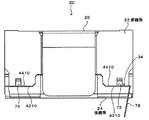
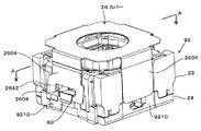
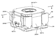
 rear spring 34 is formed, the camera module 20 is assembled using the spring member 80, and the rear spring 34 is separated from the spring member 80 during the assembly process. Sometimes an excessive force is prevented from acting on the rear spring 34.

(凹部82)
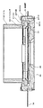
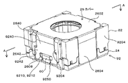
図6、図8、図38に示すように、後スプリング34の延在方向の端部を挟持する後鏡筒24の部分と前鏡筒22の部分の外面は、それら挟持する部分の周囲の箇所の外面25よりも窪んで凹部82を形成している。
図8、図39、図40に示すように、後スプリング34の延在方向の端部は、周囲の箇所の外面25の仮想延長面よりも内側に偏位した箇所に位置している。
後鏡筒24は、前鏡筒22と反対に位置する後端面2402(本実施の形態では底壁44の後面)を有し、凹部82は、後端面2402に開放状に設けられている。
後鏡筒24で構成される凹部82の底面8202は、後端面2402に向かうにつれて凹部82の深さを次第に大きくする傾斜面で形成されている。
(Concave part 82)
As shown in FIGS. 6, 8, and 38, the outer surface of the portion of the rear barrel 24 and the portion of the front barrel 22 that sandwich the end portion in the extending direction of the rear spring 34 is around the portion to be sandwiched. A recessed portion 82 is formed so as to be recessed from the outer surface 25 of the portion.
As shown in FIGS. 8, 39, and 40, the end portion of the rear spring 34 in the extending direction is located at a location displaced inward from the virtual extension surface of the outer surface 25 of the surrounding location.
The rear lens barrel 24 has a rear end surface 2402 (in the present embodiment, the rear surface of the bottom wall 44) positioned opposite to the front lens barrel 22, and the recess 82 is provided on the rear end surface 2402 in an open shape.
The bottom surface 8202 of the recess 82 formed by the rear lens barrel 24 is formed as an inclined surface that gradually increases the depth of the recess 82 toward the rear end surface 2402.

(組み立て)
次に、図2を参照してカメラモジュール20の組み立て方法について説明する。
まず、レンズ保持部30に、コイルホルダ56が取着されたコイル52を組み付ける。
すなわち、レンズ保持部材30の筒部3002の後端をコイル52の前端からコイル52の内周に挿入し、図33に示すように、筒部3002の後端面3020にコイルホルダ56の各取り付け部5610を当て付けることで、レンズ保持部材30の筒部3002にコイル52を装着する。
筒部3002にコイル52を装着したならば、調整治具を用いて、レンズ保持部材30とコイル52とを、撮像光学系28の光軸方向において、また、光軸と直交する面内において位置決めを行う。
次いで、筒部3002とコイル52との間に接着剤を充填することによりレンズ保持部材30とコイル52とを接着する。
接着剤が硬化されることにより、コイル52のレンズ保持部材30への取り付けが完了する。
次いで、スプリング部材80のうちの後スプリング24をレンズ保持部材30に取着し、これにより、レンズ保持部材30、スプリング部材80、コイル52、コイルホルダ56が組み付けられた中間組み立て体U(図2)が構成される。
(assembly)
Next, a method for assembling the camera module 20 will be described with reference to FIG.
First, the coil 52 to which the coil holder 56 is attached is assembled to the lens holding unit 30.
That is, the rear end of the cylindrical portion 3002 of the lens holding member 30 is inserted into the inner periphery of the coil 52 from the front end of the coil 52, and each attachment portion of the coil holder 56 is attached to the rear end surface 3020 of the cylindrical portion 3002, as shown in FIG. The coil 52 is attached to the cylindrical portion 3002 of the lens holding member 30 by applying 5610.
If the coil 52 is mounted on the cylindrical portion 3002, the lens holding member 30 and the coil 52 are positioned in the optical axis direction of the imaging optical system 28 and in a plane orthogonal to the optical axis using an adjustment jig. I do.
Next, the lens holding member 30 and the coil 52 are bonded together by filling an adhesive between the cylindrical portion 3002 and the coil 52.
When the adhesive is cured, the attachment of the coil 52 to the lens holding member 30 is completed.
Next, the rear spring 24 of the spring member 80 is attached to the lens holding member 30, whereby an intermediate assembly U (FIG. 2) in which the lens holding member 30, the spring member 80, the coil 52, and the coil holder 56 are assembled. ) Is configured.

後鏡筒24に中間組み立て体Uを組み付ける。
すなわち、後スプリング34の各孔76に後鏡筒24の各ピン48を挿通して中間組み立て体Uを後鏡筒24の上部に載置する。
これにより、後鏡筒24に対する中間組み立て体Uの撮像光学系28の光軸と直交する方向の位置決めがなされる。
The intermediate assembly U is assembled to the rear barrel 24.
That is, each pin 48 of the rear barrel 24 is inserted into each hole 76 of the rear spring 34, and the intermediate assembly U is placed on the upper portion of the rear barrel 24.
As a result, the intermediate assembly U is positioned with respect to the rear lens barrel 24 in the direction orthogonal to the optical axis of the imaging optical system 28.

図34は前鏡筒22を後方から見たマグネット50とマグネット位置決め面4202との位置関係を示す後面図、図35はマグネット50とマグネット位置決め面4202との位置関係を示す斜視図、図36は前鏡筒22とマグネット50と後鏡筒24との組み立て状態を前鏡筒22の一部を破断して示す斜視図、図37は図36のA矢視図である。
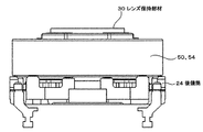
次に、図11に示すように、中間組み立て体Uのコイル52の外周に、ヨーク54に取着されたマグネット50を被せ、図36、図37に示すように、マグネット50の後端面5012を後鏡筒24の当接面4440上に載置する。
次に、図11、図34乃至図37に示すように、マグネット50の外周面5011に前鏡筒22を被せて前鏡筒22の当接面4002をマグネット50の前端面5010に当て付ける。
これにより、マグネット50の外周面5011が前鏡筒22のマグネット位置決め面4202に当て付けられる。
さらに、図18、図31に示すように、前鏡筒22の第1位置決め部4220を後鏡筒24の第3位置決め部4420に係合させると共に、前鏡筒22の第2位置部4230を後鏡筒24の第4位置決め部4430に係合させる。
これにより、マグネット50の撮像光学系28の光軸方向および光軸方向と直交する方向の双方の位置決めがなされる。
この際、後スプリング34の支持片72、74の孔76の周囲の部分が、前鏡筒22の合わせ面4210と後鏡筒24の合わせ面4410との間で挟持される。
したがって、スプリング部材80の矩形枠8002と、第1接続部8004と、外部接続端子78と、第2接続部8006とが前鏡筒22および後鏡筒24の輪郭の外側に露出した状態となる。
34 is a rear view showing the positional relationship between the magnet 50 and the magnet positioning surface 4202 when the front lens barrel 22 is viewed from the rear, FIG. 35 is a perspective view showing the positional relationship between the magnet 50 and the magnet positioning surface 4202, and FIG. FIG. 37 is a perspective view showing the assembled state of the front lens barrel 22, the magnet 50, and the rear lens barrel 24 with a part of the front lens barrel 22 broken, and FIG.
Next, as shown in FIG. 11, the magnet 50 attached to the yoke 54 is put on the outer periphery of the coil 52 of the intermediate assembly U, and the rear end surface 5012 of the magnet 50 is attached as shown in FIGS. 36 and 37. It is placed on the contact surface 4440 of the rear lens barrel 24.
Next, as shown in FIGS. 11, 34 to 37, the front lens barrel 22 is put on the outer peripheral surface 5011 of the magnet 50, and the contact surface 4002 of the front lens barrel 22 is applied to the front end surface 5010 of the magnet 50.
As a result, the outer peripheral surface 5011 of the magnet 50 is brought into contact with the magnet positioning surface 4202 of the front lens barrel 22.
Further, as shown in FIGS. 18 and 31, the first positioning portion 4220 of the front lens barrel 22 is engaged with the third positioning portion 4420 of the rear lens barrel 24, and the second position portion 4230 of the front lens barrel 22 is changed. The rear lens barrel 24 is engaged with the fourth positioning portion 4430.
Thereby, both the optical axis direction of the imaging optical system 28 of the magnet 50 and the direction orthogonal to the optical axis direction are positioned.
At this time, portions around the holes 76 of the support pieces 72 and 74 of the rear spring 34 are sandwiched between the mating surface 4210 of the front lens barrel 22 and the mating surface 4410 of the rear lens barrel 24.
Accordingly, the rectangular frame 8002 of the spring member 80, the first connection portion 8004, the external connection terminal 78, and the second connection portion 8006 are exposed outside the contours of the front barrel 22 and the rear barrel 24. .

次に、図5に示すように、カバー26を前鏡筒22の上に被せて、その係合溝2608を後鏡筒24の係合突起60に係合させる。詳細には、カバー26を前鏡筒22の上に被せて、カバー26の上面部2602と後鏡筒24の底壁44との間に前鏡筒22を挟持させる。
これにより前鏡筒22と、中間組み立て体Uと、マグネット50が組み込まれたヨーク54と、後鏡筒24とが結合される。
Next, as shown in FIG. 5, the cover 26 is placed on the front lens barrel 22, and the engagement groove 2608 is engaged with the engagement protrusion 60 of the rear lens barrel 24. Specifically, the cover 26 is placed on the front lens barrel 22, and the front lens barrel 22 is sandwiched between the upper surface portion 2602 of the cover 26 and the bottom wall 44 of the rear lens barrel 24.
As a result, the front lens barrel 22, the intermediate assembly U, the yoke 54 in which the magnet 50 is incorporated, and the rear lens barrel 24 are coupled.

次に、後スプリング34から矩形枠8002を切り離す。
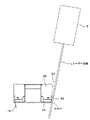
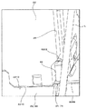
図38、図39、図40、図41はスプリング部材80の第2接続部8006のレーザー光線Lによる切断動作の説明図である。
第1の接続部8004の切断から説明する。
レーザー光源2からのレーザー光線Lを、前鏡筒22および後鏡筒24の外面25から突出する第1接続部8004の部分に向けて照射する。
これにより、第1接続部8004の部分がレーザー光線Lにより溶断され、矩形枠8002と支持片72とが切断される。
第2接続部8006の切断は次のように行う。
図38、図39、図40に示すように、前鏡筒22および後鏡筒24の外面25の斜め前方にレーザー光源2を位置させ、このレーザー光源2から凹部82に位置する第2接続部8006に向けて斜めにレーザー光線Lを照射する。
より詳細には、レーザー光線Lを凹部82内で凹部82が開放された後鏡筒24の後端面2402側に向けて照射する。
これにより、レーザー光線Lは、その一部が凹部82の内側に位置した状態で凹部82に位置する第2接続部8006に照射される。
その結果、図40、図41に示すように、凹部82に位置する第2接続部8006の部分がレーザー光線Lにより溶断され、矩形枠8002と支持片74とが切断される。
このようにして第2接続部8006が切断されることにより、図8に示すように、後スプリング34の延在方向の端部、すなわち、支持片74の端部は、凹部82内に位置して前鏡筒22および後鏡筒24の外面25の仮想延長面よりも内側に偏位した箇所に位置している。
以上のようにしてスプリング部材80から後スプリング34が切り離される。
Next, the rectangular frame 8002 is separated from the rear spring 34.
38, 39, 40, and 41 are explanatory views of the cutting operation by the laser beam L of the second connection portion 8006 of the spring member 80. FIG.
A description will be given from the cutting of the first connection portion 8004.
The laser beam L from the laser light source 2 is irradiated toward the first connecting portion 8004 protruding from the outer surface 25 of the front lens barrel 22 and the rear lens barrel 24.
Thereby, the part of the 1st connection part 8004 is melted by the laser beam L, and the rectangular frame 8002 and the support piece 72 are cut | disconnected.
The second connection part 8006 is disconnected as follows.
As shown in FIGS. 38, 39, and 40, the laser light source 2 is positioned obliquely in front of the outer surface 25 of the front lens barrel 22 and the rear lens barrel 24, and the second connection portion positioned in the recess 82 from the laser light source 2. The laser beam L is irradiated obliquely toward 8006.
More specifically, the laser beam L is irradiated toward the rear end surface 2402 side of the lens barrel 24 after the recess 82 is opened in the recess 82.
Thereby, the laser beam L is irradiated to the second connection portion 8006 positioned in the recess 82 in a state where a part of the laser beam L is positioned inside the recess 82.
As a result, as shown in FIGS. 40 and 41, the portion of the second connection portion 8006 located in the recess 82 is melted by the laser beam L, and the rectangular frame 8002 and the support piece 74 are cut.
By cutting the second connection portion 8006 in this way, as shown in FIG. 8, the end portion of the rear spring 34 in the extending direction, that is, the end portion of the support piece 74 is located in the recess 82. The front lens barrel 22 and the rear lens barrel 24 are located at locations deviated inward from the virtual extension surface of the outer surface 25.
As described above, the rear spring 34 is separated from the spring member 80.

スプリング部材80から後スプリング34が切り離されたならば、前鏡筒22の合わせ面4210と後鏡筒24の合わせ面4410との間で挟持され前鏡筒22および後鏡筒24の外方に突出した外部接続端子78を、図3に示すように後方に屈曲させる。
次いで、撮像素子36を後鏡筒44の底壁44に取着し、各外部接続端子78を基板58に半田付けすることによって、カメラモジュール20が完成する。
If the rear spring 34 is separated from the spring member 80, the rear spring 34 is sandwiched between the mating surface 4210 of the front lens barrel 22 and the mating surface 4410 of the rear lens barrel 24 and outward of the front lens barrel 22 and the rear lens barrel 24. The protruding external connection terminal 78 is bent backward as shown in FIG.
Next, the image pickup device 36 is attached to the bottom wall 44 of the rear barrel 44, and each external connection terminal 78 is soldered to the substrate 58, whereby the camera module 20 is completed.

(効果)
以上説明したように、本実施の形態によれば、後スプリング34の延在方向の端部を挟持する後鏡筒24の部分と前鏡筒22の部分の外面25は、それら挟持する部分の周囲の箇所の外面25よりも窪んで凹部82を形成し、後スプリング34の延在方向の端部は、周囲の箇所の外面25の仮想延長面よりも内側に偏位した箇所に位置している。
したがって、後スプリング34の延在方向の端部が前鏡筒22および後鏡筒24の輪郭の内側に留まっているため、カメラモジュール20の外形寸法の小型化を図る上で有利となり、ひいては、カメラモジュール20を備える電子機器の小型化を図る上で有利となる。
また、本実施の形態では、凹部82が後鏡筒24の後端面2402に開放状に設けられているため、レーザー光線Lを、後鏡筒24の側面に対して斜め方向から照射でき、したがって、後鏡筒24と前鏡筒22とで挟持された後スプリング34の延在方向の端部を凹部82内の底面寄りの箇所に位置させることが可能となる。
特に本実施の形態では、凹部82の底面を、凹部82が開放される側に向かうにつれて凹部82の深さを次第に大きくする傾斜面8202で形成したので、レーザー光線Lをより斜め方向から照射でき、後鏡筒24と前鏡筒22とで挟持された後スプリング34の延在方向の端部を凹部82内の底面寄りの箇所により近づけて位置させることが可能となる。
また、後鏡筒24に形成する凹部82は、上述のようにレーザー光線Lを斜め方向から照射できる程度の大きさで足りるため、凹部82の大きさを必要最低限の寸法で形成でき、小型化を図りつつ、カメラモジュール20の部品や部材の収容スペースを確保する上で有利となる。
(effect)
As described above, according to the present embodiment, the portion of the rear barrel 24 that sandwiches the end portion of the rear spring 34 in the extending direction and the outer surface 25 of the portion of the front barrel 22 are the portions of the portion to be sandwiched. A recess 82 is formed by being recessed from the outer surface 25 of the surrounding location, and the end portion of the rear spring 34 in the extending direction is located at a location displaced inward from the virtual extension surface of the outer surface 25 of the surrounding location. Yes.
Therefore, since the end portion of the rear spring 34 in the extending direction remains inside the outlines of the front lens barrel 22 and the rear lens barrel 24, it is advantageous in reducing the outer dimensions of the camera module 20, and as a result, This is advantageous in reducing the size of the electronic device including the camera module 20.
Further, in the present embodiment, since the concave portion 82 is provided in an open shape on the rear end surface 2402 of the rear lens barrel 24, the laser beam L can be applied to the side surface of the rear lens barrel 24 from an oblique direction. It is possible to position the end in the extending direction of the rear spring 34 sandwiched between the rear lens barrel 24 and the front lens barrel 22 at a location near the bottom surface in the recess 82.
In particular, in the present embodiment, the bottom surface of the concave portion 82 is formed by the inclined surface 8202 that gradually increases the depth of the concave portion 82 as it goes to the side where the concave portion 82 is opened. It is possible to position the end in the extending direction of the rear spring 34 sandwiched between the rear lens barrel 24 and the front lens barrel 22 closer to the portion near the bottom surface in the recess 82.
In addition, since the concave portion 82 formed in the rear barrel 24 is sufficient to be able to irradiate the laser beam L from an oblique direction as described above, the size of the concave portion 82 can be formed with the minimum necessary size, and the size can be reduced. This is advantageous in securing a housing space for the parts and members of the camera module 20.

また、本実施の形態では、後スプリング34にレーザー光線Lを照射した場合について説明したが、本発明は、前スプリング32にレーザー光線Lを照射する場合にも無論適用可能である。
また、本実施の形態では、カメラモジュール20が組み込まれる電子機器10が携帯電話機である場合について説明したが、本発明の撮像装置は、例えば、PDA、ノート型パーソナルコンピュータなどの携帯情報端末、あるいは、デジタルスチルカメラ、ビデオカメラなどの種々の電子機器に広く適用可能である。
また、本実施の形態では、駆動部が、レンズ保持部に取着されたコイルと、鏡筒(前鏡筒あるいは後鏡筒)に取着されたマグネットとで構成されたいわゆるムービングコイル方式である。
そのため、後スプリング34は、互いに分離され前記コイルの両端にそれぞれ電気的に接続された2つのスプリング分割体で構成されている。
したがって、本実施の形態によれば、スプリング部材80により2つのスプリング分割体34が一体的に保持されているため、組み立て時において、支持片72、74の孔76に後鏡筒24のピン48を挿通するといった極めて簡単な作業により、各スプリング分割体34Aを後鏡筒24に対して精度良く位置決めすることができる。
なお、本発明は、駆動部が、レンズ保持部に取着されたマグネットと、鏡筒(前鏡筒あるいは後鏡筒)に取着されたコイルとで構成されているいわゆるムービングマグネット方式である場合にも無論適用可能である。
また、本発明は、カメラモジュール以外の種々の電子デバイス、電気部品においてスプリングを切断する場合に広く適用可能であることは無論である。
In this embodiment, the case where the rear spring 34 is irradiated with the laser beam L has been described. However, the present invention is naturally applicable to the case where the front spring 32 is irradiated with the laser beam L.
Further, in the present embodiment, the case where the electronic device 10 in which the camera module 20 is incorporated is a mobile phone, but the imaging apparatus of the present invention is, for example, a portable information terminal such as a PDA or a notebook personal computer, or It can be widely applied to various electronic devices such as digital still cameras and video cameras.
Further, in the present embodiment, the drive unit is a so-called moving coil system configured with a coil attached to the lens holding part and a magnet attached to a lens barrel (front lens barrel or rear lens barrel). is there.
Therefore, the rear spring 34 is composed of two spring divided bodies that are separated from each other and electrically connected to both ends of the coil.
Therefore, according to the present embodiment, since the two spring divided bodies 34 are integrally held by the spring member 80, the pin 48 of the rear barrel 24 is inserted into the hole 76 of the support pieces 72 and 74 during assembly. Each spring divided body 34 </ b> A can be accurately positioned with respect to the rear lens barrel 24 by an extremely simple operation such as inserting the.
The present invention is a so-called moving magnet system in which the drive unit is composed of a magnet attached to a lens holding part and a coil attached to a lens barrel (front lens barrel or rear lens barrel). Of course, this is applicable.
Needless to say, the present invention can be widely applied when cutting springs in various electronic devices and electrical components other than camera modules.

次に、後スプリング34について説明する。
図42は後スプリング34の平面図、図43は後スプリング34の要部拡大図、図44は図25のEE線断面図である。なお、説明の便宜上、図44において撮像光学系28、レンズ保持部材30の図示は省略している。
次に、後スプリング34の構成について詳細に説明する。
後スプリング34は、レンズ保持部30を撮像光学系28の光軸に沿って移動可能に支持しており、レンズ保持部30の周方向に間隔をおいて4つ設けられている。
各後スプリング34は、図42、図43に示すように、撮像光学系28の光軸と直交する面内において互いに直交する方向にそれぞれ延在する第1アーム部84と第2アーム部86とを含んで構成されている。
第1、第2アーム部84、86は、厚さが薄く幅が小さい2つのばね板が、それらの厚さ方向を光軸と平行する方向に向けて互いに平行に帯状に延在することで構成されている。
第1、第2アーム部84、86が直交する箇所から離れた第1、第2アーム部84、86の延在方向の端部は、2つのばね板が、2つのばね板間の間隔Wよりも大きな寸法の直径Dからなる円弧部88で接続されている。
第1、第2アーム部84、86が直交する箇所において第1、第2アーム部84、86の各2つのばね板のうちの一方のばね板は互いに接続されている。
第1、第2アーム部84、86が直交する箇所において第1アーム部84の2つのばね板のうちの他方のばね板の延在方向の他方の端部は、レンズ保持部30の外周に沿って円弧状に延在する被保持片90として形成され、この被保持片90はレンズ保持部30に取着される。この被保持片90は上述の円弧部70を構成している。
図42に示すように、第1、第2アーム部84、86が直交する箇所において第2アーム部86の2つのばね板のうちの他方のばね板の延在方向の他方の端部91は、鏡筒92に取着される。本実施の形態では、この他方の端部91は孔76が設けられた環状の支持片72、74として形成され、鏡筒92は、図2に示すように、光軸方向に分割可能な前鏡筒22と後鏡筒24とで構成されている。
Next, the rear spring 34 will be described.
42 is a plan view of the rear spring 34, FIG. 43 is an enlarged view of a main part of the rear spring 34, and FIG. 44 is a sectional view taken along the line EE in FIG. For convenience of explanation, the imaging optical system 28 and the lens holding member 30 are not shown in FIG.
Next, the configuration of the rear spring 34 will be described in detail.
The rear spring 34 supports the lens holding unit 30 so as to be movable along the optical axis of the imaging optical system 28, and four springs 34 are provided at intervals in the circumferential direction of the lens holding unit 30.
As shown in FIGS. 42 and 43, each rear spring 34 includes a first arm portion 84 and a second arm portion 86 that extend in directions orthogonal to each other in a plane orthogonal to the optical axis of the imaging optical system 28, respectively. It is comprised including.
The first and second arm portions 84 and 86 are formed by two spring plates having a small thickness and a small width extending in a strip shape in parallel with each other in a direction parallel to the optical axis. It is configured.
The end portions in the extending direction of the first and second arm portions 84 and 86 that are separated from the position where the first and second arm portions 84 and 86 are orthogonal to each other are arranged such that two spring plates have an interval W between the two spring plates. They are connected by an arc portion 88 having a diameter D of a larger dimension.
One of the two spring plates of each of the first and second arm portions 84 and 86 is connected to each other at a location where the first and second arm portions 84 and 86 are orthogonal to each other.
The other end in the extending direction of the other spring plate of the two spring plates of the first arm portion 84 at the location where the first and second arm portions 84 and 86 are orthogonal to each other is on the outer periphery of the lens holding portion 30. It is formed as a held piece 90 extending in an arc shape along this, and this held piece 90 is attached to the lens holding portion 30. The held piece 90 constitutes the arc portion 70 described above.
As shown in FIG. 42, the other end 91 in the extending direction of the other spring plate of the two spring plates of the second arm portion 86 at the location where the first and second arm portions 84 and 86 are orthogonal to each other is The lens barrel 92 is attached. In the present embodiment, the other end portion 91 is formed as an annular support piece 72, 74 provided with a hole 76, and the lens barrel 92 can be divided into the optical axis direction as shown in FIG. The lens barrel 22 and the rear lens barrel 24 are configured.

そして、互いに隣接する2つの後スプリング34の被保持片90の延在方向の端部は接続されている。このように被保持片90が接続されることでスプリング分割体34Aが構成されている。
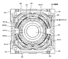
各後スプリング34の第1アーム部84は、撮像光学系28の光軸と直交する面内において互いに直交するX軸方向とY軸方向のうちX軸方向に平行して設けられ、各後スプリング34の第2アーム部86は、Y軸方向に平行して設けられている。
And the edge part of the extension direction of the to-be-held piece 90 of the two rear springs 34 adjacent to each other is connected. In this way, the split pieces 34A are configured by connecting the held pieces 90.
The first arm portion 84 of each rear spring 34 is provided in parallel to the X-axis direction out of the X-axis direction and the Y-axis direction orthogonal to each other in a plane orthogonal to the optical axis of the imaging optical system 28. 34 second arm portions 86 are provided in parallel to the Y-axis direction.

図42に示すように、鏡筒92は直方体状を呈し、レンズ保持部30は円筒状を呈し、レンズ保持部30の外周面と鏡筒92の角部との間に、前後に延在する三角柱状の空間Stが4つ設けられている。
4つの後スプリング34はそれぞれ空間Stに配設されている。
各後スプリング34はそれらの第1、第2アーム部84、86を鏡筒92の角部の壁部に平行させてそれぞれ配設されている。
As shown in FIG. 42, the lens barrel 92 has a rectangular parallelepiped shape, the lens holding portion 30 has a cylindrical shape, and extends forward and backward between the outer peripheral surface of the lens holding portion 30 and the corner portion of the lens barrel 92. Four triangular column-shaped spaces St are provided.
The four rear springs 34 are respectively disposed in the space St.
Each rear spring 34 is disposed with its first and second arm portions 84 and 86 parallel to the corner wall portion of the lens barrel 92.

次に後スプリング34の鏡筒90への組み付けについて説明する。
レンズ保持部30に取着されたコイルホルダ56の後面5620(図33)に各後スプリング34の被保持片90(円弧部70)が接着剤により接着され、したがって、各後スプリング34の被保持片90は、コイルホルダ56を介してレンズ保持部30に取着される。
各後スプリング34の端部91(支持片72、74)の孔76が後鏡筒24のピン48にそれぞれ挿入され、端部91が、図10に示すように、前鏡筒22の合わせ面4210と後鏡筒24の合わせ面4410との間で挟持され、これにより、各後スプリング34の他方の端部91が鏡筒92に取着される。
Next, assembly of the rear spring 34 to the lens barrel 90 will be described.
A held piece 90 (arc portion 70) of each rear spring 34 is adhered to the rear surface 5620 (FIG. 33) of the coil holder 56 attached to the lens holding portion 30 with an adhesive. The piece 90 is attached to the lens holding unit 30 via the coil holder 56.
The holes 76 of the end portions 91 (support pieces 72 and 74) of the rear springs 34 are respectively inserted into the pins 48 of the rear barrel 24, and the end portions 91 are mating surfaces of the front barrel 22 as shown in FIG. 4210 and the mating surface 4410 of the rear lens barrel 24, whereby the other end 91 of each rear spring 34 is attached to the lens barrel 92.

(レンズ保持部材30のストッパ構造)
次に、図25、図44を参照してレンズ保持部材30のストッパ構造について説明する。
本実施の形態では、図25に示すように、前記X軸は後鏡筒24の対向する2組の辺のうち一方の組の辺4402と平行する方向に延在し、前記Y軸は後鏡筒24の対向する2組の辺のうち他方の組の辺4404と平行する方向に延在している。
(Stopper structure of lens holding member 30)
Next, the stopper structure of the lens holding member 30 will be described with reference to FIGS.
In the present embodiment, as shown in FIG. 25, the X-axis extends in a direction parallel to one set of sides 4402 of the two opposing sides of the rear barrel 24, and the Y-axis is the rear The lens barrel 24 extends in a direction parallel to the other side 4404 of the two opposing sides of the lens barrel 24.

図25、図44に示すように、コイルホルダ56の外周部で、2つの軸部5602とそれぞれ90度位相を異ならせた2箇所に、ストッパ凸部5630がコイルホルダ56の半径方向外方にそれぞれ突設されている。したがって、2つのストッパ凸部5630は、コイルホルダ56の外周部に180度位相を異ならせた箇所に位置している。
本実施の形態では、2つのストッパ凸部5630は、コイルホルダ56のY軸方向の両側に位置している。
各ストッパ凸部5630は、撮像光学28の光軸およびY軸を含む平面と平行しかつX軸方向において対向する2つの第1当接面5630Aと、撮像光学系28の光軸およびX軸を含む平面と平行する1つの第2当接面5630Aとを有している。
一方、各ストッパ凸部5630に臨む後鏡筒24の箇所には、ストッパ凸部5630に対応するストッパ凹部2410がそれぞれ形成されている。
ストッパ凹部2410は、各第1当接面5630AとX軸方向に間隔をおいて対向する2つの第3当接面2410Aと、第2当接面5630BとY軸方向に間隔をおいて対向する第4当接面2410Bとを有している。
したがって、ストッパ凸部5630の第1当接面5630Aがストッパ凹部2410の第3当接面2410Aに当接することで、コイルホルダ56(レンズ保持部30)のX軸方向における移動限界位置が決定され、ストッパ凸部5630の第2当接面5630Bがストッパ凹部2410の第4当接面2410Bに当接することで、コイルホルダ56(レンズ保持部30)のY軸方向における移動限界位置が決定される。
これらレンズ保持部30のX軸方向およびY軸方向の移動限界位置は、レンズ保持部30がそれら移動限界位置まで移動した場合に、後スプリング34が永久変形を生じない範囲に設定されている。
As shown in FIG. 25 and FIG. 44, the stopper convex portion 5630 is disposed radially outward of the coil holder 56 at two locations on the outer periphery of the coil holder 56 that are 90 degrees out of phase with the two shaft portions 5602. Each is protruding. Accordingly, the two stopper projections 5630 are located at locations where the phase of the outer periphery of the coil holder 56 is changed by 180 degrees.
In the present embodiment, the two stopper protrusions 5630 are located on both sides of the coil holder 56 in the Y-axis direction.
Each stopper convex portion 5630 has two first contact surfaces 5630A parallel to a plane including the optical axis and the Y axis of the imaging optical 28 and facing each other in the X axis direction, and the optical axis and the X axis of the imaging optical system 28. And a second abutment surface 5630A parallel to the plane including the second abutment surface 5630A.
On the other hand, a stopper concave portion 2410 corresponding to the stopper convex portion 5630 is formed at a position of the rear barrel 24 facing each stopper convex portion 5630.
The stopper recess 2410 opposes each of the first abutment surfaces 5630A with two third abutment surfaces 2410A facing each other at an interval in the X-axis direction and opposite each of the second abutment surfaces 5630B at an interval in the Y-axis direction. And a fourth contact surface 2410B.
Accordingly, the first contact surface 5630A of the stopper convex portion 5630 contacts the third contact surface 2410A of the stopper concave portion 2410, whereby the movement limit position in the X-axis direction of the coil holder 56 (lens holding portion 30) is determined. The second contact surface 5630B of the stopper convex portion 5630 comes into contact with the fourth contact surface 2410B of the stopper concave portion 2410, whereby the movement limit position in the Y-axis direction of the coil holder 56 (lens holding portion 30) is determined. .
The movement limit positions of the lens holding unit 30 in the X-axis direction and the Y-axis direction are set in a range where the rear spring 34 does not undergo permanent deformation when the lens holding unit 30 moves to the movement limit position.

上述の構成によれば、カメラモジュール20が組み込まれた電子機器10が床の上に落下するなどして、カメラモジュール20に撮像光学系28の光軸と直交する方向の衝撃が加わった場合、レンズ保持部30は前記衝撃が加わった方向と反対方向に移動しようとする。
この際、後スプリング34の第1、第2アーム部84、86がレンズ保持部30の移動に伴い弾性変形することで、レンズ保持部30に加わる力を吸収、緩和する。
言い換えると、本発明のカメラモジュールは、収容空間を形成する鏡筒と、撮像光学系を保持し前記収容空間に収容されたレンズ保持部と、前記鏡筒に支持され前記撮影光学系で導かれた被写体像を撮像する撮像素子と、前記レンズ保持部を前記撮像光学系の光軸に沿って移動可能に支持する複数のスプリングとを有し、前記各スプリングは、前記撮像光学系の光軸と直交する面内において互いに直交する方向にそれぞれ延在する第1アーム部と第2アーム部とを含んで構成され、前記第1、第2アーム部は、2つのばね板が、それらの厚さ方向を前記光軸と平行する方向に向けて互いに平行に帯状に延在することで構成され、前記第1、第2アーム部が直交する箇所から離れた前記第1、第2アーム部の延在方向の端部は、前記2つのばね板が、前記2つのばね板間の間隔よりも大きな寸法の直径からなる円弧部で接続され、前記第1、第2アーム部が直交する箇所において前記第1、第2アーム部の各2つのばね板のうちの一方のばね板は互いに接続され、前記第1、第2アーム部が直交する箇所において前記第1アーム部の2つのばね板のうちの他方のばね板の延在方向の他方の端部は、前記レンズ保持部に取着され、前記第1、第2アーム部が直交する箇所において前記第2アーム部の2つのばね板のうちの他方のばね板の延在方向の他方の端部は、前記鏡筒に取着されている。
ここで、第1アーム部84はX軸方向に平行して設けられ、第2アーム部86はY軸方向に平行して設けられているため、言い換えると、第1、第2アーム部84、86の延在方向が互いに直交しているため、レンズ保持部30に対して光軸と直交する面内に沿って作用する力であれば、第1、第2アーム部84、86の双方が同時に弾性変形することで力を吸収、緩和する。
したがって、第1、第2アーム部84、86の何れか一方に力が集中することがないため、後スプリング34の耐久性の向上を図りつつ、後スプリング34の小型化を図れ、ひいては、カメラモジュール20の小型化を図る上で有利となる。
なお、第1、第2アーム部84、86の延在方向が互いに直交していない場合は、光軸と直交する方向の衝撃が加わった場合に、第1、第2アーム部84、86の何れか一方に力が集中するおそれがあり、後スプリング34の耐久性の向上を図る上で不利がある。
According to the above-described configuration, when the electronic device 10 in which the camera module 20 is incorporated falls on the floor and the camera module 20 is subjected to an impact in a direction orthogonal to the optical axis of the imaging optical system 28, The lens holding unit 30 tends to move in a direction opposite to the direction in which the impact is applied.
At this time, the first and second arm portions 84 and 86 of the rear spring 34 are elastically deformed as the lens holding portion 30 moves, so that the force applied to the lens holding portion 30 is absorbed and relaxed.
In other words, the camera module of the present invention includes a lens barrel that forms an accommodation space, a lens holding unit that holds an imaging optical system and is accommodated in the accommodation space, and is supported by the barrel and guided by the imaging optical system. An imaging element that captures the subject image, and a plurality of springs that support the lens holding portion so as to be movable along the optical axis of the imaging optical system, wherein each spring is an optical axis of the imaging optical system. The first arm portion and the second arm portion each extend in a direction orthogonal to each other in a plane orthogonal to the first and second arm portions. The first and second arm portions are configured by extending in a strip shape in parallel with each other in a direction parallel to the optical axis, and the first and second arm portions are separated from a position orthogonal to each other. The end in the extending direction is the two springs Are connected by a circular arc portion having a diameter larger than the distance between the two spring plates, and each of the two springs of the first and second arm portions at a location where the first and second arm portions are orthogonal to each other. One of the plates is connected to each other, and the other of the two spring plates of the first arm portion in the extending direction of the other one at the location where the first and second arm portions are orthogonal to each other. An end portion is attached to the lens holding portion, and the other of the two spring plates of the second arm portion in the extending direction of the other spring plate at a position where the first and second arm portions are orthogonal to each other. The end is attached to the lens barrel.
Here, since the first arm portion 84 is provided in parallel with the X-axis direction and the second arm portion 86 is provided in parallel with the Y-axis direction, in other words, the first and second arm portions 84, Since the extending directions of 86 are orthogonal to each other, both the first and second arm portions 84 and 86 can be applied to the lens holding unit 30 as long as the force acts along a plane perpendicular to the optical axis. At the same time, it absorbs and relaxes the force by elastic deformation.
Accordingly, no force is concentrated on any one of the first and second arm portions 84 and 86, so that the rear spring 34 can be reduced in size while improving the durability of the rear spring 34. This is advantageous in reducing the size of the module 20.
When the extending directions of the first and second arm portions 84 and 86 are not orthogonal to each other, when an impact in a direction orthogonal to the optical axis is applied, the first and second arm portions 84 and 86 There is a possibility that force may concentrate on either one, which is disadvantageous in improving the durability of the rear spring 34.

また、レンズ保持部30の外周面と鏡筒92の角部との間に前後に延在する三角柱状の4つの空間Stに後スプリング34をそれぞれ配設したので、デッドスペースである各空間Stを有効に利用でき、カメラモジュール20の小型化を図る上でより一層有利となる。   Further, since the rear springs 34 are disposed in the four triangular prism-shaped spaces St extending forward and backward between the outer peripheral surface of the lens holding portion 30 and the corners of the lens barrel 92, each space St that is a dead space is provided. Can be used effectively, which is further advantageous in reducing the size of the camera module 20.

次に、後スプリング34の他の例について説明する。
図45は後スプリング34が後鏡筒24に組み付けられた斜視図、図46は図45のA矢視図、図47は後スプリング34がレンズ保持部30に取着された斜視図、図48は後スプリング34の平面図、図49は後スプリング34の支持片の拡大平面図である。
Next, another example of the rear spring 34 will be described.
45 is a perspective view in which the rear spring 34 is assembled to the rear barrel 24, FIG. 46 is a perspective view taken along the arrow A in FIG. 45, and FIG. 47 is a perspective view in which the rear spring 34 is attached to the lens holding portion 30. FIG. 49 is a plan view of the rear spring 34, and FIG. 49 is an enlarged plan view of a support piece of the rear spring 34.

本例は、図45乃至図48に示すように、後スプリング34の支持片72、74に孔76と同軸上で円弧状に延在する溝94を孔76の周方向に間隔をおいて複数設けたものである。
この場合、支持片72、74の部分のうち溝94を除いた孔76の外周に延在する環状の部分を前鏡筒22の合わせ面4210と後鏡筒24の合わせ面4410との間で挟持することで、各後スプリング34が鏡筒92に取着される。
また、溝94は、図48に示すように、単一の円周に沿って形成してもよいし、あるいは、図49に示すように、半径が異なる2つ以上の円周に沿って形成してもよい。
支持片72、74に溝94を形成することにより、図48、図49に示すように、支持片72、74に、撮像光学系28の光軸と直交する方向に沿って弾性変形可能なばね部96が構成される。
したがって、このような構成によれば、ばね部96によっても撮像光学系28の光軸と直交する方向における力を吸収、緩和することができるため、後スプリング34の耐久性の向上を図りつつ、後スプリング34の小型化を図る上でより一層有利となる。
In this example, as shown in FIGS. 45 to 48, a plurality of grooves 94 extending in an arc shape coaxially with the hole 76 are formed in the support pieces 72 and 74 of the rear spring 34 at intervals in the circumferential direction of the hole 76. It is provided.
In this case, an annular portion extending to the outer periphery of the hole 76 excluding the groove 94 among the support pieces 72 and 74 is disposed between the mating surface 4210 of the front lens barrel 22 and the mating surface 4410 of the rear lens barrel 24. Each rear spring 34 is attached to the lens barrel 92 by clamping.
Further, the groove 94 may be formed along a single circumference as shown in FIG. 48, or may be formed along two or more circumferences having different radii as shown in FIG. May be.
By forming the grooves 94 in the support pieces 72 and 74, as shown in FIGS. 48 and 49, the springs that can be elastically deformed along the direction perpendicular to the optical axis of the imaging optical system 28 are provided on the support pieces 72 and 74. Part 96 is configured.
Therefore, according to such a configuration, since the force in the direction orthogonal to the optical axis of the imaging optical system 28 can be absorbed and relaxed by the spring portion 96, the durability of the rear spring 34 is improved, This is even more advantageous in reducing the size of the rear spring 34.

(カバー26の取り付け構造)
次にカバー26の取り付け構造について説明する。
図50はカバー26の鏡筒92への取り付け動作を説明する斜視図、図51は図50のAA線断面図、図52はカバー26の鏡筒92への取り付け動作を説明する斜視図、図53は図52のAA線断面図、図54はカバー26の鏡筒92への取り付け動作を説明する斜視図、図55は図54のAA線断面図、図56はカバー26の鏡筒92への取り付け動作を説明する斜視図、図57は図56のAA線断面図、図58はカバー26の鏡筒92への取り付け動作を説明する斜視図、図59は図58のAA線断面図、図60(A)は実施の形態におけるカバー26の断面図、(B)は比較例におけるカバー26の断面図である。
(Mounting structure of cover 26)
Next, the attachment structure of the cover 26 will be described.
50 is a perspective view for explaining the operation of attaching the cover 26 to the lens barrel 92, FIG. 51 is a sectional view taken along the line AA of FIG. 50, and FIG. 52 is a perspective view for explaining the operation of attaching the cover 26 to the lens barrel 92. 53 is a sectional view taken along the line AA in FIG. 52, FIG. 54 is a perspective view for explaining the operation of attaching the cover 26 to the barrel 92, FIG. 55 is a sectional view taken along the line AA in FIG. 57 is a cross-sectional view taken along the line AA in FIG. 56, FIG. 58 is a perspective view explaining the operation of attaching the cover 26 to the lens barrel 92, and FIG. 59 is a cross-sectional view taken along the line AA in FIG. 60A is a cross-sectional view of the cover 26 in the embodiment, and FIG. 60B is a cross-sectional view of the cover 26 in the comparative example.

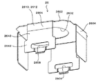
上述のように、鏡筒92には、撮像光学系28を収容する収容空間S(図11)が前後に延在形成され、鏡筒92は、図12、図50、図51に示すように、矩形状の前面9202と、前面9202の4辺から後方に延在する4つの側面9204を備えている。ここで後方とは撮像素子36側であり、前方とは撮像素子36から離れる被写体側である。
鏡筒92は、上述のように前鏡筒22と、前鏡筒22の後側に配置される後鏡筒24とで構成され、前面9202は前鏡筒22に設けられ、各側面9204は前鏡筒22と後鏡筒24にわたって設けられている。
各側面9204には、前後に延在する凹部9210が設けられている。
側面9204および凹部9210の底面9212が前面9202に交わる箇所に、前面9202に近づくにつれて鏡筒92の内側に変位する傾斜面9214が設けられている。
As described above, the storage space S (FIG. 11) for storing the imaging optical system 28 extends in the front-rear direction in the lens barrel 92, and the lens barrel 92 is formed as shown in FIGS. , A rectangular front surface 9202, and four side surfaces 9204 extending rearward from four sides of the front surface 9202. Here, the rear is the image sensor 36 side, and the front is the subject side away from the image sensor 36.
The lens barrel 92 is configured by the front lens barrel 22 and the rear lens barrel 24 disposed on the rear side of the front lens barrel 22 as described above, the front surface 9202 is provided on the front lens barrel 22, and each side surface 9204 is The front lens barrel 22 and the rear lens barrel 24 are provided.
Each side surface 9204 is provided with a recess 9210 extending in the front-rear direction.
An inclined surface 9214 that is displaced toward the inside of the lens barrel 92 as it approaches the front surface 9202 is provided at a location where the side surface 9204 and the bottom surface 9212 of the recess 9210 intersect with the front surface 9202.

そして、前鏡筒22と後鏡筒24とを組み付ける金属板または弾性を有する金属板からなるカバー26が設けられている。
図28乃至図30、図50、図51に示すように、カバー26は前面9202に当接する矩形状の前面部2602と、前面部2602の4辺から後方に延在し凹部9210に収容されて凹部9210の底面9212に当接する弾性変形可能な脚片2604と、少なくとも対向する1組の脚片2604に設けられた係合孔2608とを有している。
本実施の形態では、脚片2604が上述した側面部2604を構成し、係合孔2608が上述した係合溝2608を構成している。
前面部2602には、上述した開口2606が形成され、開口2606により撮像光学系28(図11)の光路が確保されている。
図29、図50に示すように、係合孔2608が形成された脚片2604は、前面部2602側に位置する前部2640と、後鏡筒24の後端側に位置する後部2642とを有している。
係合孔2608は後部2642に設けられ、後部2642の幅は、前部2640の幅よりも大きな寸法で形成されている。
なお、この係合孔2608が形成された脚片2604の形状に対応して、係合孔2608が形成された脚片2604が収容される凹部9210は、図12、図50に示すように、脚片2604の前部2640が収容される幅の前部9240と、この前部9240の幅よりも大きく脚片2604の後部2642が収容される幅の後部9242とで形成されている。
A cover 26 made of a metal plate to which the front lens barrel 22 and the rear lens barrel 24 are assembled or a metal plate having elasticity is provided.
As shown in FIGS. 28 to 30, 50, and 51, the cover 26 has a rectangular front surface portion 2602 that abuts the front surface 9202, and extends rearward from four sides of the front surface portion 2602, and is accommodated in the recess 9210. It has an elastically deformable leg piece 2604 that abuts against the bottom surface 9212 of the recess 9210 and an engagement hole 2608 provided in at least one pair of the leg pieces 2604 facing each other.
In the present embodiment, the leg piece 2604 constitutes the side surface portion 2604 described above, and the engagement hole 2608 constitutes the engagement groove 2608 described above.
The opening 2606 described above is formed in the front surface portion 2602, and the optical path of the imaging optical system 28 (FIG. 11) is secured by the opening 2606.
As shown in FIGS. 29 and 50, the leg piece 2604 in which the engagement hole 2608 is formed includes a front part 2640 positioned on the front surface part 2602 side and a rear part 2642 positioned on the rear end side of the rear lens barrel 24. Have.
The engagement hole 2608 is provided in the rear portion 2642, and the width of the rear portion 2642 is formed to be larger than the width of the front portion 2640.
Corresponding to the shape of the leg piece 2604 in which the engagement hole 2608 is formed, the recess 9210 in which the leg piece 2604 in which the engagement hole 2608 is formed is accommodated, as shown in FIGS. The front portion 9240 has a width that accommodates the front portion 2640 of the leg piece 2604, and the rear portion 9242 has a width that is larger than the width of the front portion 9240 and accommodates the rear portion 2642 of the leg piece 2604.

図50、図51に示すように、後鏡筒24に位置する凹部9210の底面9212に、側面9204の高さ以下の高さを有し係合孔2608に係合可能な係合凸部60が設けられている。本実施の形態では、係合凸部60により上述した係合突起60が構成されている。
係合凸部60よりも後鏡筒24の後端寄りの底面9212箇所は、底面9212よりも窪んだ収容凹部9250として形成されている。
そして、係合孔2608よりも先端に位置する脚片2604の先端の箇所は、収容凹部9250に収容されるように他の脚片2604箇所に対して窪んだ窪み片2604Aとして形成されている。
さらに、窪み片2604Aの先端は他の脚片2604箇所と同じ高さまで屈曲され起立された起立片2604Bとして形成されている。
図58、図59に示すように、カバー26の前面部2602が鏡筒92の前面9202に当接し、各脚片2604が凹部9210の底面9212に当接し、各係合孔2608に係合凸部60が係合した状態で前鏡筒22と後鏡筒24とは組み付けられた状態に保持される。
この保持された状態で、図7、図8に示すように、カバー26の各脚片2604は、側面9204と同じ高さかあるいは側面9204よりも底面9212寄りに位置している。
As shown in FIGS. 50 and 51, the engagement convex portion 60 that has a height equal to or lower than the height of the side surface 9204 on the bottom surface 9212 of the concave portion 9210 located in the rear lens barrel 24 and can be engaged with the engagement hole 2608. Is provided. In the present embodiment, the engagement protrusion 60 is configured by the engagement protrusion 60.
A portion of the bottom surface 9212 closer to the rear end of the rear barrel 24 than the engaging convex portion 60 is formed as an accommodating concave portion 9250 that is recessed from the bottom surface 9212.
The tip of the leg piece 2604 positioned at the tip of the engagement hole 2608 is formed as a hollow piece 2604A that is recessed with respect to the other leg pieces 2604 so as to be housed in the housing recess 9250.
Furthermore, the tip of the hollow piece 2604A is formed as an upright piece 2604B which is bent and raised to the same height as the other leg pieces 2604.
As shown in FIGS. 58 and 59, the front surface portion 2602 of the cover 26 is in contact with the front surface 9202 of the lens barrel 92, the leg pieces 2604 are in contact with the bottom surface 9212 of the recess 9210, and the engagement protrusions 2608 are engaged with the engagement protrusions 2608. With the portion 60 engaged, the front lens barrel 22 and the rear lens barrel 24 are held in an assembled state.
7 and 8, each leg piece 2604 of the cover 26 is located at the same height as the side surface 9204 or closer to the bottom surface 9212 than the side surface 9204 in this held state.

次にカバー26の鏡筒92への組み付けについて説明する。
まず、図50、図51に示すように、カバー26の各脚片2604を、鏡筒92の前方から各側面9204の凹部9210に挿入する。
この際、係合孔2608が設けられた脚片2604の後部2642の後端、および、係合孔2608が設けられていない脚片2604の後端は、それぞれ傾斜面9214に案内されることにより鏡筒92の外方に向かって変位する。
したがって、係合孔2608が設けられた脚片2604の後部2642は、側面9204に向けて円滑に案内され、係合孔2608が設けられていない脚片2604の後端は、凹部9210の底面9212に向けて円滑に案内される。
カバー26の前面部260を鏡筒92に向けて移動させると、図52乃至図55に示すように、係合孔2608が設けられた脚片2604の後部2642の両側は、凹部9210の両側の側面9204に沿って凹部9210の後部9242に近接する方向に案内され、係合孔2608が設けられていない脚片2604の後端は、凹部9210の底面9212に沿って後方に案内される。
カバー26の移動により、図56、図57に示すように、係合孔2608が設けられた脚片2604の後部2642の両側が凹部9210の両側の側面9204に沿って案内されることで、係合孔2608が設けられた脚片2604の窪み片2604Aは、係合凸部60の外側に変位しつつ後方に移動する。
さらなるカバー26の移動により、やがて、図58、図59に示すように、カバー26の前面部2602が鏡筒92の前面9202に当接する。
すると、係合孔2608が設けられた脚片2604の後部2642が凹部9210の後部9242に収容され、窪み片2604Aは収容凹部9250に収容され、係合孔2608が係合部60に係合し、脚片2604の前部2640が凹部9210の前部9240に収容され、したがって、係合孔2608が設けられた脚片2604は、凹部9210の底面9212に当接した状態となる。
また、係合孔2608が設けられていない脚片2604は、凹部9210の底面9212に当接し、かつ、脚片2604の後端が鏡筒92の後端近傍箇所に位置した状態となる。
このようにしてカバー26の各係合孔2608に鏡筒92の係合凸部60が係合することにより、前鏡筒22と後鏡筒24とが組み付けられた状態に保持される。
Next, assembly of the cover 26 to the lens barrel 92 will be described.
First, as shown in FIGS. 50 and 51, the leg pieces 2604 of the cover 26 are inserted into the concave portions 9210 of the side surfaces 9204 from the front of the lens barrel 92.
At this time, the rear end of the rear portion 2642 of the leg piece 2604 provided with the engagement hole 2608 and the rear end of the leg piece 2604 not provided with the engagement hole 2608 are guided by the inclined surface 9214, respectively. The lens barrel 92 is displaced outward.
Accordingly, the rear portion 2642 of the leg piece 2604 provided with the engagement hole 2608 is smoothly guided toward the side surface 9204, and the rear end of the leg piece 2604 not provided with the engagement hole 2608 is the bottom surface 9212 of the recess 9210. It is guided smoothly toward.
When the front surface portion 260 of the cover 26 is moved toward the lens barrel 92, both sides of the rear portion 2642 of the leg pieces 2604 provided with the engagement holes 2608 are arranged on both sides of the concave portion 9210 as shown in FIGS. The rear end of the leg piece 2604 that is guided along the side surface 9204 in the direction approaching the rear portion 9242 of the concave portion 9210 and is not provided with the engagement hole 2608 is guided rearward along the bottom surface 9212 of the concave portion 9210.
As shown in FIGS. 56 and 57, the movement of the cover 26 guides both sides of the rear portion 2642 of the leg piece 2604 provided with the engagement holes 2608 along the side surfaces 9204 on both sides of the recess 9210. The recessed piece 2604A of the leg piece 2604 provided with the joint hole 2608 moves rearward while being displaced to the outside of the engaging convex portion 60.
Due to the further movement of the cover 26, the front portion 2602 of the cover 26 comes into contact with the front surface 9202 of the lens barrel 92 as shown in FIGS. 58 and 59.
Then, the rear portion 2642 of the leg piece 2604 provided with the engagement hole 2608 is accommodated in the rear portion 9242 of the recess 9210, the recess piece 2604A is accommodated in the accommodation recess 9250, and the engagement hole 2608 engages with the engagement portion 60. The front part 2640 of the leg piece 2604 is accommodated in the front part 9240 of the recess 9210, and thus the leg piece 2604 provided with the engagement hole 2608 is in contact with the bottom surface 9212 of the recess 9210.
The leg piece 2604 not provided with the engagement hole 2608 is in contact with the bottom surface 9212 of the recess 9210 and the rear end of the leg piece 2604 is positioned in the vicinity of the rear end of the lens barrel 92.
In this way, the engagement projections 60 of the lens barrel 92 are engaged with the engagement holes 2608 of the cover 26, whereby the front lens barrel 22 and the rear lens barrel 24 are held in an assembled state.

以上の構成によれば、鏡筒92の凹部9210の底面9212に側面9204の高さ以下の高さを有しカバー26の係合孔2608に係合可能な係合凸部60が設けられ、各係合孔2608に係合凸部60が係合した状態で前鏡筒22と後鏡筒24とは組み付けられた状態に保持され、この保持された状態で、各脚片2604は、側面9204と同じ高さかあるいは側面9204よりも底面9210寄りに位置している。
言い換えると、本発明のカメラモジュールは、撮影光学系を収容する収容空間が前後に延在形成された鏡筒を備え、前記鏡筒は、矩形状の前面と、前記前面の4辺から後方に延在する4つの側面を備え、前記鏡筒は、前記前面を有する前鏡筒と、前記前鏡筒の後側に配置される後鏡筒とで構成され、前記各側面には、前後に延在する凹部が設けられ、金属板からなるカバーが設けられ、前記カバーは前記前面に当接する矩形状の前面部と、前記前面部の4辺から後方に延在し前記凹部に収容されて凹部の底面に当接する弾性変形可能な脚片と、少なくとも対向する1組の脚片に設けられた係合孔とを有し、前記凹部の底面に前記側面の高さ以下の高さを有し前記係合孔に係合可能な係合凸部が設けられ、前記カバーの前記前面部が前記鏡筒の前面に当接し、各脚片が前記凹部に収容されて凹部の底面に当接し、各係合孔に前記係合凸部が係合した状態で前記前鏡筒と前記後鏡筒とは組み付けられた状態に保持され、この保持された状態で、前記カバーの各脚片は、前記側面と同じ高さかあるいは前記側面よりも前記底面寄りに位置している。
したがって、図7、図8に示すように、鏡筒92の側面9204の輪郭の外側に突出する部分が無いため、すなわち、矩形の輪郭の外側に突出する箇所がないため、カメラモジュール20の占有スペースを縮小しつつ外形寸法の小型化を図る上で有利となり、ひいては、電子機器10の小型化を図る上で有利となる。
According to the above configuration, the engagement protrusion 60 is provided on the bottom surface 9212 of the recess 9210 of the lens barrel 92 and has a height equal to or lower than the height of the side surface 9204 and can be engaged with the engagement hole 2608 of the cover 26. The front lens barrel 22 and the rear lens barrel 24 are held in an assembled state with the engagement projections 60 engaged with the respective engagement holes 2608, and in this held state, each leg piece 2604 has a side surface. It is located at the same height as 9204 or closer to the bottom surface 9210 than the side surface 9204.
In other words, the camera module of the present invention includes a lens barrel in which an accommodation space for accommodating a photographing optical system is formed to extend in the front-rear direction. The lens barrel has a rectangular front surface and a rear side from four sides of the front surface. Four side surfaces extending, and the lens barrel is configured by a front lens barrel having the front surface and a rear lens barrel disposed on the rear side of the front lens barrel. An extending recess is provided, and a cover made of a metal plate is provided. The cover is a rectangular front surface that abuts the front surface, and extends rearward from four sides of the front surface and is accommodated in the recess. It has an elastically deformable leg piece that contacts the bottom surface of the recess, and an engagement hole provided in at least one pair of opposing leg pieces, and the bottom surface of the recess has a height equal to or less than the height of the side surface. And an engaging convex portion that can be engaged with the engaging hole is provided, and the front surface portion of the cover is connected to the lens barrel. The front lens barrel and the rear lens barrel are assembled in a state in which each leg piece is accommodated in the recess and is in contact with the bottom surface of the recess, and the engagement protrusion is engaged with each engagement hole. The leg pieces of the cover are located at the same height as the side surface or closer to the bottom surface than the side surface.
Accordingly, as shown in FIGS. 7 and 8, there is no portion protruding outside the outline of the side surface 9204 of the lens barrel 92, that is, there is no portion protruding outside the rectangular outline, so that the camera module 20 occupies it. This is advantageous in reducing the outer dimensions while reducing the space, and is advantageous in reducing the size of the electronic device 10.

また、カバー26の係合孔2608が形成された脚片2604の後部2642の幅が前部2640の幅よりも大きな寸法で形成され、係合孔2608が形成された脚片2604が収容される凹部9210は、脚片2604の前部2640が収容される幅の前部9240と、この前部9240の幅よりも大きく脚片2604の後部2642が収容される幅の後部9242とを有している。
したがって、カバー26を鏡筒92に取着する際に、係合孔2608が形成された脚片2604の後部2642を鏡筒92の側面9204によって案内することで、すなわち、後部2642の両側を凹部9210の前部9240の両側の側面9204で持ち上げつつ後方に案内するので、円滑に脚片2604を凹部9410に収容させることができ、組み立て性の向上を図る上で有利となることは無論のこと、組み立て時にカバー26と鏡筒92との間で生じる摩擦を減らすことができ、したがって、摩擦によって鏡筒92が削れて生じた塵埃が撮像光学系28や撮像素子36に付着するなどして画質に影響を及ぼすことを防止する上でも有利となる。
また、側面9204および凹部9210の底面9212が前面9204に交わる箇所に、前面9204に近づくにつれて鏡筒92の内側に変位する傾斜面9214が設けられているため、カバー26の組み付け時に、脚片2604の後端が傾斜面9214により円滑に案内されるため、組み立て性の向上を図る上でより有利となることは無論のこと、上記と同様に組み立て時にカバー26と鏡筒92との間で生じる摩擦を減らすことで画質の劣化を防止する上でもより有利となる。
Further, the width of the rear portion 2642 of the leg piece 2604 in which the engagement hole 2608 of the cover 26 is formed is larger than the width of the front portion 2640, and the leg piece 2604 in which the engagement hole 2608 is formed is accommodated. The concave portion 9210 has a front portion 9240 having a width in which the front portion 2640 of the leg piece 2604 is accommodated, and a rear portion 9242 having a width larger than the width of the front portion 9240 and in which the rear portion 2642 of the leg piece 2604 is accommodated. Yes.
Therefore, when the cover 26 is attached to the lens barrel 92, the rear portion 2642 of the leg piece 2604 in which the engagement hole 2608 is formed is guided by the side surface 9204 of the lens barrel 92, that is, both sides of the rear portion 2642 are recessed. Since it is guided backward while being lifted by the side surfaces 9204 on both sides of the front portion 9240 of the 9210, the leg pieces 2604 can be smoothly accommodated in the concave portions 9410, which is of course advantageous for improving the assemblability. Thus, friction generated between the cover 26 and the lens barrel 92 during assembly can be reduced. Therefore, dust generated by scraping the lens barrel 92 due to friction adheres to the image pickup optical system 28 and the image sensor 36, and the like. This is also advantageous in preventing the influence on the spillover.
In addition, an inclined surface 9214 that is displaced toward the inside of the lens barrel 92 as it approaches the front surface 9204 is provided at a location where the side surface 9204 and the bottom surface 9212 of the recess 9210 intersect with the front surface 9204. Since the rear end of the rear surface is smoothly guided by the inclined surface 9214, it is of course advantageous for improving the assembling property. As described above, it occurs between the cover 26 and the lens barrel 92 at the time of assembling. Reducing the friction is more advantageous in preventing image quality deterioration.

また、図11、図28乃至図30、図50、図51、図60(A)に示すように、後鏡筒24と前鏡筒24とがカバー26により組みつけられた状態で、前面部2602が前面9202に当接する面と反対の面の全域から、脚片2604が底面2612に当接する面と反対の面で前面部2602寄りの箇所にわたり、光の反射を防止する塗装2612が施されている。
すなわち、塗装2612によって光の反射を防止する反射防止部2610が形成されている。
仮に、このような塗装2612が施されていないと、図1に示すように、カメラモジュール20が電子機器10の第1の鏡筒14に組み込まれている場合、カバー26の前面部2602が、第1の筐体14の開口1410を介して視認された際の美観性が確保できない。
また、開口1410から進入した外光が、前面部2602と筐体の内面との間で(あるいは前面部2602と開口1410に設けられた透明板との間で)反射して撮像光学系28に入り、撮像素子36で撮像される画像の品質に悪影響を及ぼす不都合がある。
そこで、カバー26に塗装2612を施して反射防止部2610を形成することにより、美観性を確保し、また、画像品質の向上が図られている。
このような美観性および画質の確保を図る上では、図60(B)に示すように、前面部2602の前面にのみ塗装2612を施して反射防止部2610を形成し、脚片2604には反射防止部2610を形成しないことも考えられる。
しかしながら、多くの場合、カメラモジュール20を取り扱う際に、カバー26の前面部2602の全体を覆うように弱い粘着力を有する保護シートを貼り付ける。
塗装2612のうち、前面部2602と脚片2604との境目の部分に(前面部2602と脚片2604とを接続する屈曲部分に)位置する縁部2614は、他の部分に比較して剥がれやすいため、保護シートを剥がす際に、縁部2614から塗装2612が部分的に剥がれるおそれがある。
そこで、本実施の形態では、図60(A)に示すように、前面部2602が前面9202に当接する面と反対の面の全域から、脚片2604が底面2612に当接する面と反対の面で前面部2602寄りの箇所にわたり塗装2612を施したので、前面部2602から保護シートを剥がす際に塗装2612が剥がれることを防止する上で有利となる。
11, 28 to 30, 50, 51, and 60 (A), the front lens barrel 24 and the front lens barrel 24 are assembled together by the cover 26 in the front portion. A coating 2612 for preventing light reflection is applied from the entire area of the surface opposite to the surface where 2602 contacts the front surface 9202 to the portion near the front surface portion 2602 on the surface opposite to the surface where the leg piece 2604 contacts the bottom surface 2612. ing.
That is, an antireflection portion 2610 that prevents reflection of light by the coating 2612 is formed.
If such a coating 2612 is not applied, as shown in FIG. 1, when the camera module 20 is incorporated in the first barrel 14 of the electronic device 10, the front surface portion 2602 of the cover 26 is The aesthetics when visually recognized through the opening 1410 of the first housing 14 cannot be secured.
In addition, external light entering from the opening 1410 is reflected between the front surface portion 2602 and the inner surface of the housing (or between the front surface portion 2602 and the transparent plate provided in the opening 1410) and is reflected on the imaging optical system 28. There is an inconvenience that adversely affects the quality of the image picked up by the image pickup device 36.
Therefore, the coating 2612 is applied to the cover 26 to form the antireflection portion 2610, thereby ensuring aesthetics and improving the image quality.
In order to ensure such aesthetics and image quality, as shown in FIG. 60B, only the front surface of the front surface portion 2602 is coated 2612 to form an antireflection portion 2610, and the leg pieces 2604 are reflected. It is also conceivable that the prevention part 2610 is not formed.
However, in many cases, when the camera module 20 is handled, a protective sheet having a weak adhesive force is attached so as to cover the entire front surface portion 2602 of the cover 26.
Of the coating 2612, the edge 2614 located at the boundary between the front surface portion 2602 and the leg piece 2604 (at the bent portion connecting the front surface portion 2602 and the leg piece 2604) is more easily peeled off than the other portions. Therefore, when the protective sheet is peeled off, the paint 2612 may be partially peeled off from the edge portion 2614.
Therefore, in the present embodiment, as shown in FIG. 60A, the surface opposite to the surface where the leg piece 2604 contacts the bottom surface 2612 from the entire surface opposite to the surface where the front surface portion 2602 contacts the front surface 9202. Since the coating 2612 is applied to the portion near the front surface portion 2602, it is advantageous in preventing the coating 2612 from being peeled off when the protective sheet is peeled off from the front surface portion 2602.

なお、図3、図4に示すように、係合孔2608が設けられていない脚片2604を、後鏡筒24の後端からさらに後方に延在して基板58に半田付けするようにしてもよい。この基板58は、上述したように後鏡筒26の後端に配置され、撮像光学系28により導かれる被写体像を撮像する撮像素子36が搭載された基板58である。
また、図4に示すように、係合孔2608が設けられていない脚片2604を、マグネット50に接触させて配置してもよい。このマグネット50は、上述したようにレンズ保持部30を移動させる駆動部を構成するマグネット50である。
このように構成すると、基板58および撮像素子36で発生した熱は、脚片2604からカバー26に伝導され、また、コイル30からマグネット50に伝導された熱は、脚片2604からカバー26に伝導され、したがって、カバー26を介して放熱がなされる。
したがって、カバー26により撮像素子36、基板58、マグネット50、コイル52が効率的に冷却され、撮像素子36、基板58、駆動部38の動作の安定化を図る上で有利となる。
As shown in FIGS. 3 and 4, a leg piece 2604 not provided with an engagement hole 2608 extends further rearward from the rear end of the rear barrel 24 and is soldered to the substrate 58. Also good. As described above, the substrate 58 is a substrate 58 on which the imaging element 36 that is disposed at the rear end of the rear barrel 26 and captures the subject image guided by the imaging optical system 28 is mounted.
Further, as shown in FIG. 4, leg pieces 2604 that are not provided with the engagement holes 2608 may be arranged in contact with the magnet 50. The magnet 50 is a magnet 50 that constitutes a drive unit that moves the lens holding unit 30 as described above.
With this configuration, heat generated in the substrate 58 and the image sensor 36 is conducted from the leg piece 2604 to the cover 26, and heat conducted from the coil 30 to the magnet 50 is conducted from the leg piece 2604 to the cover 26. Therefore, heat is radiated through the cover 26.
Therefore, the image pickup device 36, the substrate 58, the magnet 50, and the coil 52 are efficiently cooled by the cover 26, which is advantageous in stabilizing the operation of the image pickup device 36, the substrate 58, and the drive unit 38.

なお、駆動部が、レンズ保持部に取着されたコイルと、鏡筒に取着されたマグネットとで構成されたいわゆるムービングコイル方式である場合について説明した。
しかしながら、駆動部が、レンズ保持部に取着されたマグネットと、鏡筒に取着されたコイルとで構成されているいわゆるムービングマグネット方式である場合にも無論適用可能である。
In addition, the case where the drive unit is a so-called moving coil system constituted by a coil attached to the lens holding part and a magnet attached to the lens barrel has been described.
However, the present invention can of course be applied to a case where the driving unit is a so-called moving magnet system including a magnet attached to the lens holding part and a coil attached to the lens barrel.

(A)、(B)は本実施の形態に係るカメラモジュール20が組み込まれた電子機器の一例を示す外観図である。(A), (B) is an external view which shows an example of the electronic device with which the camera module 20 which concerns on this Embodiment was integrated. カメラモジュール20の組み立て説明図である。4 is an assembly explanatory diagram of the camera module 20. FIG. カメラモジュール20の分解図である。4 is an exploded view of the camera module 20. FIG. 図3のAA線断面図である。It is AA sectional view taken on the line of FIG. カメラモジュール20を前方から見た斜視図である。It is the perspective view which looked at the camera module 20 from the front. カメラモジュール20を後方から見た斜視図である。It is the perspective view which looked at the camera module 20 from back. 図5のA矢視図である。It is A arrow directional view of FIG. 図5のB矢視図である。FIG. 6 is a view taken in the direction of arrow B in FIG. 5. 図5のC矢視図である。It is C arrow line view of FIG. 図5のD矢視図である。It is D arrow line view of FIG. 図5のEE線断面図である。It is the EE sectional view taken on the line of FIG. 図5からカバー26を取り外した状態を前方から見た示す斜視図である。It is the perspective view which looked at the state which removed the cover 26 from FIG. 5 from the front. 図12を後方から見た斜視図である。It is the perspective view which looked at FIG. 12 from back. 図12のA矢視図である。It is A arrow directional view of FIG. 図12のB矢視図である。It is a B arrow line view of FIG. 図12のC矢視図である。It is C arrow line view of FIG. 図12のD矢視図である。It is D arrow line view of FIG. 図12から前鏡筒22を取り外した状態を前方から見た示す斜視図である。It is the perspective view which looked at the state which removed the front lens barrel 22 from FIG. 12 from the front. 図18を後方から見た斜視図である。It is the perspective view which looked at FIG. 18 from back. 図18のA矢視図である。It is A arrow line view of FIG. 図18のC矢視図である。It is C arrow line view of FIG. 図18のD矢視図である。It is a D arrow line view of FIG. 図18からマグネット50を取り外した状態を前方から見た示す斜視図である。It is the perspective view which showed the state which removed the magnet 50 from FIG. 18 seen from the front. 図23を後方から見た斜視図である。It is the perspective view which looked at FIG. 23 from back. 図23のA矢視図である。It is A arrow line view of FIG. 図23のC矢視図である。It is C arrow line view of FIG. 図23のD矢視図である。It is a D arrow line view of FIG. カバー26を前方から見た斜視図である。It is the perspective view which looked at the cover 26 from the front. カバー26を後方から見た斜視図である。It is the perspective view which looked at the cover 26 from back. 図28のA矢視図である。It is A arrow line view of FIG. マグネット50が前鏡筒22の内側に挿入された状態を示す斜視図である。4 is a perspective view showing a state in which a magnet 50 is inserted inside the front barrel 22. FIG. 図31のA矢視図である。FIG. 32 is a view on arrow A in FIG. 31. レンズ保持部材30、後スプリング34、コイル52、コイルホルダ56を示す斜視図である。4 is a perspective view showing a lens holding member 30, a rear spring 34, a coil 52, and a coil holder 56. FIG. 前鏡筒22を後方から見たマグネット50とマグネット位置決め面4202との位置関係を示す後面図である。7 is a rear view showing the positional relationship between a magnet 50 and a magnet positioning surface 4202 when the front lens barrel 22 is viewed from the rear. FIG. マグネット50とマグネット位置決め面4202との位置関係を示す斜視図である。6 is a perspective view showing a positional relationship between a magnet 50 and a magnet positioning surface 4202. FIG. 前鏡筒22とマグネット50と後鏡筒24との組み立て状態を前鏡筒22の一部を破断して示す斜視図である。FIG. 3 is a perspective view showing an assembled state of the front lens barrel 22, a magnet 50, and a rear lens barrel 24 with a part of the front lens barrel 22 broken away. 図36のA矢視図である。It is A arrow view of FIG. スプリング部材80の第2接続部8006のレーザー光線Lによる切断動作の説明図である。FIG. 10 is an explanatory diagram of the cutting operation by the laser beam L of the second connection portion 8006 of the spring member 80. スプリング部材80の第2接続部8006のレーザー光線Lによる切断動作の説明図である。FIG. 10 is an explanatory diagram of the cutting operation by the laser beam L of the second connection portion 8006 of the spring member 80. スプリング部材80の第2接続部8006のレーザー光線Lによる切断動作の説明図である。FIG. 10 is an explanatory diagram of the cutting operation by the laser beam L of the second connection portion 8006 of the spring member 80. スプリング部材80の第2接続部8006のレーザー光線Lによる切断動作の説明図である。FIG. 10 is an explanatory diagram of the cutting operation by the laser beam L of the second connection portion 8006 of the spring member 80. 後スプリング34の平面図である。3 is a plan view of a rear spring 34. FIG. 後スプリング34の要部拡大図である。3 is an enlarged view of a main part of a rear spring 34. FIG. 図25のEE線断面図である。It is EE sectional view taken on the line of FIG. 第後スプリング34が後鏡筒24に組み付けられた斜視図である。FIG. 5 is a perspective view in which a first rear spring 34 is assembled to the rear barrel 24. 図45のA矢視図である。It is A arrow line view of FIG. 後スプリング34がレンズ保持部30に取着された斜視図である。FIG. 5 is a perspective view in which a rear spring 34 is attached to the lens holding unit 30. 後スプリング34の平面図である。3 is a plan view of a rear spring 34. FIG. 後スプリング34の支持片の拡大平面図である。4 is an enlarged plan view of a support piece of a rear spring 34. FIG. カバー26の鏡筒92への取り付け動作を説明する斜視図である。FIG. 6 is a perspective view for explaining an attaching operation of the cover 26 to the lens barrel 92. 図50のAA線断面図である。It is AA sectional view taken on the line of FIG. カバー26の鏡筒92への取り付け動作を説明する斜視図である。FIG. 6 is a perspective view for explaining an attaching operation of the cover 26 to the lens barrel 92. 図52のAA線断面図である。FIG. 53 is a cross-sectional view taken along line AA in FIG. 52. カバー26の鏡筒92への取り付け動作を説明する斜視図である。FIG. 6 is a perspective view for explaining an attaching operation of the cover 26 to the lens barrel 92. 図54のAA線断面図である。It is AA sectional view taken on the line of FIG. カバー26の鏡筒92への取り付け動作を説明する斜視図である。FIG. 6 is a perspective view for explaining an attaching operation of the cover 26 to the lens barrel 92. 図56のAA線断面図である。It is AA sectional view taken on the line of FIG. カバー26の鏡筒92への取り付け動作を説明する斜視図である。FIG. 6 is a perspective view for explaining an attaching operation of the cover 26 to the lens barrel 92. 図58のAA線断面図である。It is AA sectional view taken on the line of FIG. (A)は実施の形態におけるカバー26の断面図、(B)は比較例におけるカバー26の断面図である。(A) is sectional drawing of the cover 26 in embodiment, (B) is sectional drawing of the cover 26 in a comparative example.

符号の説明Explanation of symbols

20……カメラモジュール、22……前鏡筒、24……後鏡筒、25……外面、28……撮像光学系、30……レンズ保持部材、32……前スプリング、34……後スプリング、36……撮像素子、38……駆動部、82……凹部。   20 …… Camera module, 22 …… Front lens barrel, 24 …… Rear lens barrel, 25 …… Outer surface, 28 …… Imaging optical system, 30 …… Lens holding member, 32 …… Front spring, 34 …… Rear spring , 36... Image sensor, 38... Drive unit, 82.

Claims (7)

後鏡筒と、
前記後鏡筒に組みつけられ前記後鏡筒と共に収容空間を形成する前鏡筒と、
撮像光学系を保持し前記収容空間に収容されたレンズ保持部と、
前記後鏡筒に支持され前記撮影光学系で導かれた被写体像を撮像する撮像素子と、
前記レンズ保持部を前記撮像光学系の光軸に沿って移動可能に支持する案内機構と、
前記レンズ保持部を前記撮像光学系の光軸に沿って移動させる駆動部とを備え、
前記案内機構は、前記レンズ保持部を前記撮像素子側から前記撮影光学系側に付勢する後スプリングと、前記レンズ保持部を前記撮影光学系側から前記撮像素子側に付勢する前スプリングとを有し、
前記後スプリングと前記前スプリングは、ばね板が帯状に延在して構成され、
前記後スプリングと前記前スプリングの少なくとも一方のスプリングの延在方向の端部は、前記前鏡筒と前記後鏡筒とで挟持されて配設され、
前記スプリングの延在方向の端部を挟持する前記後鏡筒の部分と前記前鏡筒の部分の外面は、それら挟持する部分の周囲の箇所の外面よりも窪んで凹部を形成しており、
前記スプリングの延在方向の端部は、前記凹部内に位置し、かつ、前記周囲の箇所の外面の仮想延長面よりも内側に偏位した箇所に位置している、
カメラモジュール。
The rear barrel,
A front lens barrel that is assembled to the rear lens barrel and forms a housing space with the rear lens barrel;
A lens holding unit that holds the imaging optical system and is housed in the housing space;
An image sensor that captures a subject image supported by the rear lens barrel and guided by the imaging optical system;
A guide mechanism for supporting the lens holding portion movably along the optical axis of the imaging optical system;
A driving unit that moves the lens holding unit along the optical axis of the imaging optical system;
The guide mechanism includes a rear spring that biases the lens holding portion from the imaging element side to the photographing optical system side, and a front spring that biases the lens holding portion from the photographing optical system side to the imaging element side. Have
The rear spring and the front spring are configured by a spring plate extending in a strip shape,
An end portion of at least one of the rear spring and the front spring in the extending direction is sandwiched and disposed between the front lens barrel and the rear lens barrel,
The outer surface of the part of the rear lens barrel and the part of the front lens barrel that sandwich the end portion in the extending direction of the spring are recessed from the outer surface of the portion around the part to be sandwiched to form a recess,
An end portion in the extending direction of the spring is located in the concave portion, and is located at a location displaced inward from a virtual extension surface of the outer surface of the surrounding location,
The camera module.
前記前鏡筒と前記後鏡筒とで挟持されて配設されるスプリングは後スプリングであり、
前記後鏡筒は、前記前鏡筒と反対に位置する後端面を有し、
前記凹部は、前記後端面に開放状に設けられている、
請求項1記載のカメラモジュール。
The spring arranged to be sandwiched between the front lens barrel and the rear lens barrel is a rear spring,
The rear lens barrel has a rear end surface located opposite to the front lens barrel,
The recess is provided in an open shape on the rear end surface.
The camera module according to claim 1.
前記後鏡筒で構成される前記凹部の底面は、前記後端面に向かうにつれて前記凹部の深さを次第に大きくする傾斜面で形成されている、
請求項2記載のカメラモジュール。
The bottom surface of the concave portion constituted by the rear lens barrel is formed with an inclined surface that gradually increases the depth of the concave portion toward the rear end surface.
The camera module according to claim 2.
前記駆動部は、前記レンズ保持部に取着されたコイルと、前記撮像光学系の光軸に沿った推力を前記コイルに発生させるマグネットとを含んで構成され、
前記前鏡筒と前記後鏡筒とで挟持されて配設されるスプリングは、互いに分離され前記コイルの両端にそれぞれ電気的に接続された2つのスプリング分割体で構成され、
前記コイルに対する駆動電流の供給は前記2つのスプリング分割体を介してなされる、
請求項1、2または3記載のカメラモジュール。
The drive unit includes a coil attached to the lens holding unit, and a magnet that generates a thrust along the optical axis of the imaging optical system.
The spring sandwiched between the front lens barrel and the rear lens barrel is composed of two spring divided bodies that are separated from each other and electrically connected to both ends of the coil, respectively.
The drive current is supplied to the coil through the two spring divided bodies.
The camera module according to claim 1, 2 or 3.
後鏡筒と、
前記後鏡筒に組み付けられ前記後鏡筒と共に収容空間を形成する前鏡筒と、
撮像光学系を保持し前記収容空間に収容されたレンズ保持部と、
前記レンズ保持部を前記撮像光学系の光軸に沿って移動可能に支持する案内機構とを備え、
前記案内機構は、前記レンズ保持部を前記撮像素子側から前記撮影光学系側に付勢する後スプリングと、前記レンズ保持部を前記撮影光学系側から前記撮像素子側に付勢する前スプリングとを有し、
前記後鏡筒は、前記前鏡筒と反対に位置する後端面を有し、
前記前鏡筒は、前記後鏡筒と反対に位置する前端面を有するカメラモジュールの製造方法であって、
前記後スプリングと前記前スプリングのうちの一方のスプリングを、ばね板製の板材をプレス加工することで矩形枠と一体にこの矩形枠の内側に帯状に延在して形成し、
前記矩形枠寄りに位置する前記スプリングの延在方向の端部を、前記前鏡筒と前記後鏡筒とで挟持し、
前記挟持する前記後鏡筒の部分と前記前鏡筒の部分の外面を、それら挟持する部分の周囲の箇所の外面よりも窪んだ凹部に形成しておき、
レーザーを前記凹部内に照射して前記スプリングと前記矩形枠とを切り離すようにした、
カメラモジュールの製造方法。
The rear barrel,
A front lens barrel that is assembled to the rear lens barrel and forms a housing space with the rear lens barrel;
A lens holding unit that holds the imaging optical system and is housed in the housing space;
A guide mechanism for supporting the lens holding unit movably along the optical axis of the imaging optical system,
The guide mechanism includes a rear spring that biases the lens holding portion from the imaging element side to the photographing optical system side, and a front spring that biases the lens holding portion from the photographing optical system side to the imaging element side. Have
The rear lens barrel has a rear end surface located opposite to the front lens barrel,
The front lens barrel is a method of manufacturing a camera module having a front end surface located opposite to the rear lens barrel,
One of the rear spring and the front spring is formed by extending a strip inside the rectangular frame integrally with the rectangular frame by pressing a spring plate.
The end in the extending direction of the spring located near the rectangular frame is sandwiched between the front lens barrel and the rear lens barrel,
The outer surface of the part of the rear lens barrel and the part of the front lens barrel to be sandwiched are formed in a recessed portion that is recessed from the outer surface of the portion around the part to be sandwiched,
A laser was irradiated into the recess to separate the spring and the rectangular frame.
Manufacturing method of camera module.
前記凹部を前記後端面側あるいは前記前端面側に開放状に形成しておき、
レーザーを前記凹部内で前記開放された側に向けて照射する、
請求項5記載のカメラモジュールの製造方法。
The concave portion is formed open on the rear end surface side or the front end surface side,
Irradiating a laser toward the open side in the recess,
The method for manufacturing a camera module according to claim 5.
前記凹部の底面を、前記凹部が開放される側に向かうにつれて前記凹部の深さを次第に大きくする傾斜面で形成しておく、
請求項6記載のカメラモジュールの製造方法。
The bottom surface of the concave portion is formed with an inclined surface that gradually increases the depth of the concave portion toward the side where the concave portion is opened.
The manufacturing method of the camera module of Claim 6.
JP2008161864A 2008-06-20 2008-06-20 Lens barrel and manufacturing method thereof Expired - Fee Related JP5125799B2 (en)

Priority Applications (1)

Application Number Priority Date Filing Date Title
JP2008161864A JP5125799B2 (en) 2008-06-20 2008-06-20 Lens barrel and manufacturing method thereof

Applications Claiming Priority (1)

Application Number Priority Date Filing Date Title
JP2008161864A JP5125799B2 (en) 2008-06-20 2008-06-20 Lens barrel and manufacturing method thereof

Publications (3)

Publication Number Publication Date
JP2010002722A true JP2010002722A (en) 2010-01-07
JP2010002722A5 JP2010002722A5 (en) 2011-07-21
JP5125799B2 JP5125799B2 (en) 2013-01-23

Family

ID=41584495

Family Applications (1)

Application Number Title Priority Date Filing Date
JP2008161864A Expired - Fee Related JP5125799B2 (en) 2008-06-20 2008-06-20 Lens barrel and manufacturing method thereof

Country Status (1)

Country Link
JP (1) JP5125799B2 (en)

Cited By (1)

* Cited by examiner, † Cited by third party
Publication number Priority date Publication date Assignee Title
WO2014054347A1 (en) * 2012-10-05 2014-04-10 日本電産サンキョー株式会社 Optical unit and method for producing same

Citations (7)

* Cited by examiner, † Cited by third party
Publication number Priority date Publication date Assignee Title
JPH1145453A (en) * 1997-07-25 1999-02-16 Sony Corp Optical pickup
JP2005260771A (en) * 2004-03-15 2005-09-22 Pioneer Electronic Corp Speaker apparatus
JP2005293678A (en) * 2004-03-31 2005-10-20 Pioneer Electronic Corp Holder suspension, its manufacturing method, lens driving device, and optical pickup device
JP2008033252A (en) * 2006-06-30 2008-02-14 Shicoh Eng Co Ltd Lens driving device, camera and mobil phone with camera
JP2008058946A (en) * 2007-06-13 2008-03-13 Tricore Corp VOICE COIL MOTOR TYPE mp FOCUSING ACTUATOR
JP2008112200A (en) * 2006-10-04 2008-05-15 Nidec Sankyo Corp Lens drive device
JP2008122470A (en) * 2006-11-08 2008-05-29 Nidec Sankyo Corp Lens driving device and its manufacturing method

Patent Citations (7)

* Cited by examiner, † Cited by third party
Publication number Priority date Publication date Assignee Title
JPH1145453A (en) * 1997-07-25 1999-02-16 Sony Corp Optical pickup
JP2005260771A (en) * 2004-03-15 2005-09-22 Pioneer Electronic Corp Speaker apparatus
JP2005293678A (en) * 2004-03-31 2005-10-20 Pioneer Electronic Corp Holder suspension, its manufacturing method, lens driving device, and optical pickup device
JP2008033252A (en) * 2006-06-30 2008-02-14 Shicoh Eng Co Ltd Lens driving device, camera and mobil phone with camera
JP2008112200A (en) * 2006-10-04 2008-05-15 Nidec Sankyo Corp Lens drive device
JP2008122470A (en) * 2006-11-08 2008-05-29 Nidec Sankyo Corp Lens driving device and its manufacturing method
JP2008058946A (en) * 2007-06-13 2008-03-13 Tricore Corp VOICE COIL MOTOR TYPE mp FOCUSING ACTUATOR

Cited By (3)

* Cited by examiner, † Cited by third party
Publication number Priority date Publication date Assignee Title
WO2014054347A1 (en) * 2012-10-05 2014-04-10 日本電産サンキョー株式会社 Optical unit and method for producing same
JP2014074860A (en) * 2012-10-05 2014-04-24 Nidec Sankyo Corp Optical unit and method for manufacturing optical unit
US9535259B2 (en) 2012-10-05 2017-01-03 Nidec Sankyo Corporation Optical unit and method for producing same

Also Published As

Publication number Publication date
JP5125799B2 (en) 2013-01-23

Similar Documents

Publication Publication Date Title
JP4706935B2 (en) The camera module
EP2124431B1 (en) Camera module comprising three members
JP5169361B2 (en) The camera module
JP4433303B2 (en) Lens unit and imaging device
JP4844829B2 (en) The camera module
US8107176B2 (en) Lens drive device
JP4415268B2 (en) Lens unit and imaging device
JP5338025B2 (en) The camera module
KR20100120619A (en) Camera module
KR20060092067A (en) Lens unit and imaging apparatus
US20120174574A1 (en) Drive module and electronic apparatus
JP6476981B2 (en) Lens driving device, camera module, and camera mounting device
JP2010004349A (en) Camera module
JP2008111876A (en) Camera module
JP2012255972A (en) Lens drive device, autofocus camera, and mobile terminal with camera
JP6730646B2 (en) Lens drive device, camera module, and camera mounting device
JP4596249B2 (en) Lens unit and imaging device
JP5125799B2 (en) Lens barrel and manufacturing method thereof
JP2013020237A (en) Driving module assembly and camera module
JP2008111868A (en) Camera module and solid-state imaging device
JP2015099398A (en) Lens drive device, autofocus camera, and mobile terminal with camera
JP2011209493A (en) Image pickup device

Legal Events

Date Code Title Description
RD04 Notification of resignation of power of attorney

Free format text: JAPANESE INTERMEDIATE CODE: A7424

Effective date: 20091015

A521 Request for written amendment filed

Free format text: JAPANESE INTERMEDIATE CODE: A523

Effective date: 20110607

A621 Written request for application examination

Free format text: JAPANESE INTERMEDIATE CODE: A621

Effective date: 20110607

A977 Report on retrieval

Free format text: JAPANESE INTERMEDIATE CODE: A971007

Effective date: 20120316

TRDD Decision of grant or rejection written
A01 Written decision to grant a patent or to grant a registration (utility model)

Free format text: JAPANESE INTERMEDIATE CODE: A01

Effective date: 20121002

A01 Written decision to grant a patent or to grant a registration (utility model)

Free format text: JAPANESE INTERMEDIATE CODE: A01

A61 First payment of annual fees (during grant procedure)

Free format text: JAPANESE INTERMEDIATE CODE: A61

Effective date: 20121015

FPAY Renewal fee payment (event date is renewal date of database)

Free format text: PAYMENT UNTIL: 20151109

Year of fee payment: 3

LAPS Cancellation because of no payment of annual fees