JP2010002609A - Opening/closing device and image forming apparatus - Google Patents

Opening/closing device and image forming apparatus Download PDF

Info

Publication number
JP2010002609A
JP2010002609A JP2008160619A JP2008160619A JP2010002609A JP 2010002609 A JP2010002609 A JP 2010002609A JP 2008160619 A JP2008160619 A JP 2008160619A JP 2008160619 A JP2008160619 A JP 2008160619A JP 2010002609 A JP2010002609 A JP 2010002609A
Authority
JP
Japan
Prior art keywords
opening
closing
closing part
main body
inner opening
Prior art date
Legal status (The legal status is an assumption and is not a legal conclusion. Google has not performed a legal analysis and makes no representation as to the accuracy of the status listed.)
Granted
Application number
JP2008160619A
Other languages
Japanese (ja)
Other versions
JP4935766B2 (en
Inventor
Taisei Kin
太星 金
Satoru Hori
悟 堀
Ryotaro Nomi
亮太郎 能見
Current Assignee (The listed assignees may be inaccurate. Google has not performed a legal analysis and makes no representation or warranty as to the accuracy of the list.)
Fujifilm Business Innovation Corp
Original Assignee
Fuji Xerox Co Ltd
Priority date (The priority date is an assumption and is not a legal conclusion. Google has not performed a legal analysis and makes no representation as to the accuracy of the date listed.)
Filing date
Publication date
Application filed by Fuji Xerox Co Ltd filed Critical Fuji Xerox Co Ltd
Priority to JP2008160619A priority Critical patent/JP4935766B2/en
Publication of JP2010002609A publication Critical patent/JP2010002609A/en
Application granted granted Critical
Publication of JP4935766B2 publication Critical patent/JP4935766B2/en
Expired - Fee Related legal-status Critical Current
Anticipated expiration legal-status Critical

Links

Images

Landscapes

  • Electrophotography Configuration And Component (AREA)

Abstract

<P>PROBLEM TO BE SOLVED: To prevent or restrain an inside opening/closing part from interfering with its body of the device, when an outside opening/closing part is closed, in a state with the inside opening/closing part open. <P>SOLUTION: In an opening/closing device 50, an opening/closing cover 52 is rotatably supported by an opening/closing cover hinge 54 of the body 12 of the device. On the inside of the opening/closing cover 52, the inside opening/closing part 56 is rotatably supported by the inside opening/closing hinge 58 of the opening/closing cover 52. Accordingly, the inside opening/closing part 56 is brought to an opening position toward the body 12 of the device from the opening/closing cover 52 side. Above the transformer unit 72, a rib 74 is disposed that avoids the inside opening/closing part 56 and transformer unit 72 from interfering from each other, due to the contact of a plate member 57B when the opening/closing cover 52 is closed, with the inside opening/closing part 56 open. In the middle of the transformer unit 72, a guide projection 80 for avoiding the leading end of the inside opening/closing part 56 and the guide member 78 of the body 12 of the device interfering with each other, by pressing the opening/closing part 56 toward the opening/closing cover 52. <P>COPYRIGHT: (C)2010,JPO&INPIT

Description

本発明は、開閉装置、及びこの開閉装置を備えた画像形成装置に関する。   The present invention relates to an opening / closing device and an image forming apparatus including the opening / closing device.

下記特許文献1には、両面ユニットに副回動ユニットが回動可能に支持され、両面ユニットを開放すると同時に副回動ユニットが開放される構造が開示されている。   Patent Document 1 below discloses a structure in which a sub-rotation unit is rotatably supported by a double-sided unit, and the sub-rotation unit is opened simultaneously with opening the double-sided unit.

また、下記特許文献2には、反転搬送ユニットに対して内側フレーム部材が開閉可能に設けられており、反転搬送ユニットを装置本体から離れる方向に開放した後、内側フレーム部材を装置本体に近づく方向に開放する構造が開示されている。   Further, in Patent Document 2 below, an inner frame member is provided so as to be openable and closable with respect to the reversing conveyance unit, and after opening the reversing conveyance unit in a direction away from the apparatus main body, the inner frame member approaches the apparatus main body. An open structure is disclosed.

さらに、下記特許文献3には、両面搬送路を構成する内側搬送部材と外側搬送部材とが一定の開放角を維持して開放される構造が開示されている。
特開2006−64727号公報 特開平8−202095号公報 特開2008−58449号公報
Further, Patent Document 3 below discloses a structure in which an inner conveyance member and an outer conveyance member constituting a double-side conveyance path are opened while maintaining a constant opening angle.
JP 2006-64727 A JP-A-8-202095 JP 2008-58449 A

本発明は、内側開閉部を開放した状態で外側開閉部を閉じるときに、内側開閉部が装置本体に干渉するのを防止又は抑制することができる開閉装置及び画像形成装置を提供することを目的とする。   An object of the present invention is to provide an opening / closing device and an image forming apparatus capable of preventing or suppressing the inner opening / closing portion from interfering with the apparatus main body when the outer opening / closing portion is closed with the inner opening / closing portion opened. And

上記問題点を解決するために、請求項1に記載の発明に係る開閉装置は、装置本体の下方に設けられた第1ヒンジを中心として開閉される外側開閉部と、前記外側開閉部の下方に設けられた第2ヒンジを中心として開閉され、かつ、前記外側開閉部側から前記装置本体側に開放される内側開閉部と、前記装置本体及び前記内側開閉部の少なくとも一方に設けられ、前記内側開閉部を開放した状態で前記外側開閉部を閉じるときに、前記内側開閉部が前記外側開閉部に近づく方向に押されて前記内側開閉部が前記装置本体と干渉しないようにガイドすると共に、前記外側開閉部を閉じた状態ではガイドする状態から外れるように配置されたガイド突起と、を有することを特徴としている。   In order to solve the above problems, an opening / closing device according to the invention described in claim 1 includes an outer opening / closing portion that opens and closes around a first hinge provided below the device main body, and a lower portion of the outer opening / closing portion. An inner opening / closing portion opened from the outer opening / closing portion side to the device main body side, and at least one of the device main body and the inner opening / closing portion. When closing the outer opening / closing part with the inner opening / closing part opened, the inner opening / closing part is pushed in a direction approaching the outer opening / closing part to guide the inner opening / closing part so as not to interfere with the apparatus main body, And a guide projection arranged so as to be out of a guiding state when the outer opening / closing part is closed.

請求項2に記載の発明は、請求項1に記載の開閉装置において、前記内側開閉部を開放した状態で前記外側開閉部を閉じるときに、前記内側開閉部の先端部が前記装置本体に衝突する前に前記内側開閉部が前記ガイド突起により押されて前記内側開閉部の先端部と前記装置本体との干渉が回避されるように構成されていることを特徴としている。   According to a second aspect of the present invention, in the switchgear according to the first aspect, when the outer opening / closing part is closed with the inner opening / closing part opened, the tip of the inner opening / closing part collides with the apparatus main body. Before the operation, the inner opening / closing part is pushed by the guide projection, and interference between the tip of the inner opening / closing part and the apparatus main body is avoided.

請求項3に記載の発明は、請求項2に記載の開閉装置において、前記外側開閉部が開放された状態で、前記第2ヒンジの支点が前記第1ヒンジの支点に対して前記装置本体と反対側に配置されると共に、前記外側開閉部を閉じた状態で、前記第2ヒンジの支点が前記第1ヒンジの支点よりも前記装置本体側に配置されており、前記外側開閉部を閉じる過程で、前記第2ヒンジの支点の軌跡が、前記第1ヒンジの支点の上方側で最大高さとなる頂点を通り、前記外側開閉部を閉じた状態で前記頂点より下方側に位置するように設定されていることを特徴としている。   According to a third aspect of the present invention, in the opening / closing apparatus according to the second aspect, the fulcrum of the second hinge is in contact with the main body of the apparatus with respect to the fulcrum of the first hinge in a state where the outer opening / closing part is opened. A process of closing the outer opening / closing part, the fulcrum of the second hinge being arranged closer to the apparatus main body than the fulcrum of the first hinge, with the outer opening / closing part being closed, disposed on the opposite side Thus, the locus of the fulcrum of the second hinge is set so as to pass through the apex having the maximum height above the fulcrum of the first hinge and to be positioned below the apex with the outer opening / closing part closed. It is characterized by being.

請求項4に記載の発明は、請求項2又は請求項3に記載の開閉装置において、前記装置本体及び前記内側開閉部の少なくとも一方に設けられ、前記内側開閉部を開放した状態で前記外側開閉部を閉じるときに、前記ガイド突起が前記装置本体及び前記内側開閉部の少なくとも一方と接触する前に、前記内側開閉部の一部が前記装置本体と干渉しないようにガイドする補助ガイド突起を有することを特徴としている。   According to a fourth aspect of the present invention, in the opening / closing device according to the second or third aspect, the outer opening / closing device is provided in at least one of the device main body and the inner opening / closing portion, and the inner opening / closing portion is opened. An auxiliary guide protrusion that guides a part of the inner opening / closing part so as not to interfere with the apparatus main body before the guide protrusion contacts at least one of the apparatus main body and the inner opening / closing part when the portion is closed. It is characterized by that.

請求項5に記載の発明は、請求項1から請求項4までのいずれか1項に記載の開閉装置において、前記装置本体及び前記内側開閉部の一方に前記ガイド突起が設けられ、前記装置本体及び前記内側開閉部の他方に、前記外側開閉部を閉じた状態で前記ガイド突起が嵌合されて前記内側開閉部が位置決めされる嵌合穴が設けられていることを特徴としている。   According to a fifth aspect of the present invention, in the opening / closing device according to any one of the first to fourth aspects, the guide protrusion is provided on one of the device main body and the inner opening / closing portion, and the device main body In addition, the other of the inner opening / closing portion is provided with a fitting hole in which the guide protrusion is fitted and the inner opening / closing portion is positioned with the outer opening / closing portion closed.

請求項6に記載の発明は、請求項1から請求項5までのいずれか1項に記載の開閉装置において、前記外側開閉部及び前記内側開閉部の一方に設けられた位置決め用突起と、前記外側開閉部及び前記内側開閉部の他方に設けられ、前記外側開閉部を閉じた状態で前記位置決め用突起が嵌合される位置決め用嵌合穴と、を有することを特徴としている。   According to a sixth aspect of the present invention, in the opening / closing device according to any one of the first to fifth aspects, the positioning protrusion provided on one of the outer opening / closing portion and the inner opening / closing portion, And a positioning fitting hole provided on the other of the outer opening and closing portion and the inner opening and closing portion and into which the positioning protrusion is fitted in a state where the outer opening and closing portion is closed.

請求項7に記載の発明は、請求項6に記載の開閉装置において、前記外側開閉部に前記位置決め用突起が設けられると共に、前記装置本体に前記ガイド突起が設けられ、前記内側開閉部に前記嵌合穴と前記位置決め用嵌合穴とが貫通するように設けられていることを特徴としている。   According to a seventh aspect of the present invention, in the opening / closing apparatus according to the sixth aspect, the positioning protrusion is provided in the outer opening / closing part, the guide protrusion is provided in the apparatus main body, and the inner opening / closing part is provided with the guide protrusion. The fitting hole and the positioning fitting hole are provided so as to penetrate therethrough.

請求項8に記載の発明に係る画像形成装置は、装置本体に設けられた記録媒体搬送路に請求項1から請求項7までのいずれか1項に記載の開閉装置が設けられ、前記外側開閉部と前記内側開閉部の間を記録媒体が搬送されることを特徴としている。   According to an eighth aspect of the present invention, there is provided an image forming apparatus comprising: the opening / closing device according to any one of the first to seventh aspects; A recording medium is transported between a part and an inner opening / closing part.

請求項1に記載の発明によれば、内側開閉部を開放した状態で外側開閉部を閉じるときに、内側開閉部が装置本体に干渉するのを防止又は抑制することができる。   According to the first aspect of the present invention, when the outer opening / closing part is closed with the inner opening / closing part opened, it is possible to prevent or suppress the inner opening / closing part from interfering with the apparatus main body.

請求項2に記載の発明によれば、内側開閉部を開放した状態で外側開閉部を閉じるときに、内側開閉部の先端部が装置本体に干渉するのを防止又は抑制することができる。   According to the second aspect of the present invention, when the outer opening / closing part is closed with the inner opening / closing part opened, it is possible to prevent or suppress the front end of the inner opening / closing part from interfering with the apparatus main body.

請求項3に記載の発明によれば、内側開閉部を開放した状態で外側開閉部を閉じるときに、内側開閉部の先端部が装置本体に干渉するのをより効果的に防止又は抑制することができる。   According to the third aspect of the present invention, when the outer opening / closing part is closed with the inner opening / closing part opened, it is possible to more effectively prevent or suppress the front end of the inner opening / closing part from interfering with the apparatus main body. Can do.

請求項4に記載の発明によれば、内側開閉部を開放した状態で外側開閉部を閉じるときに、内側開閉部の一部が装置本体に干渉するのをより確実に防止又は抑制することができる。   According to the invention described in claim 4, when the outer opening / closing part is closed with the inner opening / closing part opened, it is possible to more reliably prevent or suppress a part of the inner opening / closing part from interfering with the apparatus main body. it can.

請求項5に記載の発明によれば、外側開閉部を閉じた状態で、内側開閉部を装置本体に対して簡易に位置決めすることができる。   According to the fifth aspect of the present invention, the inner opening / closing part can be easily positioned with respect to the apparatus main body with the outer opening / closing part closed.

請求項6に記載の発明によれば、外側開閉部を閉じた状態で、外側開閉部を内側開閉部に対して簡易に位置決めすることができる。   According to the sixth aspect of the present invention, the outer opening / closing part can be easily positioned with respect to the inner opening / closing part with the outer opening / closing part closed.

請求項7に記載の発明によれば、本構成を有していない場合に比較して、外側開閉部及び内側開閉部を位置決めする構成が簡単になる。   According to the seventh aspect of the present invention, the configuration for positioning the outer opening / closing portion and the inner opening / closing portion is simplified as compared with the case where the present configuration is not provided.

請求項8に記載の発明によれば、内側開閉部を開放した状態で外側開閉部を閉じるときに、内側開閉部が装置本体に干渉するのを防止又は抑制することができる。   According to the eighth aspect of the present invention, when the outer opening / closing part is closed with the inner opening / closing part opened, the inner opening / closing part can be prevented or suppressed from interfering with the apparatus main body.

以下に、本発明に係る開閉装置を備えた画像形成装置の実施の形態を図面に基づいて説明する。   Embodiments of an image forming apparatus including an opening / closing device according to the present invention will be described below with reference to the drawings.

[第1実施形態]
(画像形成装置の全体構成)
まず、第1実施形態に係る開閉装置を備えた画像形成装置の全体構成について、図1に基づき説明する。
[First Embodiment]
(Overall configuration of image forming apparatus)
First, the overall configuration of the image forming apparatus including the opening / closing device according to the first embodiment will be described with reference to FIG.

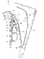
図1に示されるように、画像形成装置10は、装置本体12を備え、装置本体12の下部には、記録媒体の一例としての用紙Pが束状に積層されて収納される給紙トレイ14が配置されている。なお、記録媒体としては、用紙に限られず、プラスチックフィルム等のシート状部材、その他、画像が記録される媒体を用いてもよい。   As shown in FIG. 1, the image forming apparatus 10 includes an apparatus main body 12. A paper feed tray 14 in which sheets P as an example of a recording medium are stacked and stored in a lower portion of the apparatus main body 12. Is arranged. The recording medium is not limited to paper, and a sheet-like member such as a plastic film or other media on which an image is recorded may be used.

給紙トレイ14の先端側(図1において右端側)の直上には、用紙Pの上面の先端側に接触して給紙トレイ14から用紙Pを送り出す給紙ロール16が配置されている。   A paper feed roll 16 is disposed immediately above the front end side (the right end side in FIG. 1) of the paper feed tray 14 so as to contact the front end side of the upper surface of the paper P and feed the paper P from the paper feed tray 14.

また、装置本体12には、給紙トレイ14の先端部から延出して、緩やかに湾曲し、装置前方側(図1において右側)で上方へ向かって略垂直に延びる第1搬送路22が形成されている。この第1搬送路22に沿って、用紙搬送方向上流側(単に「上流側」という場合もある)から順に、用紙Pを挟持搬送する複数(例えば、2つ)の搬送ロール対24、画像が形成される用紙Pを静電吸着して搬送する無端状の搬送ベルト26が配置されている。   Further, the apparatus main body 12 is formed with a first conveyance path 22 that extends from the front end of the paper feed tray 14 and is gently curved and extends substantially vertically upward on the front side of the apparatus (right side in FIG. 1). Has been. Along the first transport path 22, a plurality (for example, two) of transport roller pairs 24 that sandwich and transport the paper P in order from the upstream side in the paper transport direction (sometimes simply referred to as “upstream side”), and the image An endless transport belt 26 is disposed that electrostatically attracts and transports the paper P to be formed.

搬送ベルト26は、上方に配置された巻掛ローラ27と、下方に配置された巻掛ローラ29に巻き掛けられており、巻掛ローラ27及び巻掛ローラ29のいずれかが、所定方向(図1において、時計回り方向)へ回転駆動することにより、搬送ベルト26が所定方向(図1において、時計回り方向)へ回転(循環駆動)する。   The conveyor belt 26 is wound around a winding roller 27 disposed above and a winding roller 29 disposed below, and one of the winding roller 27 and the winding roller 29 is in a predetermined direction (see FIG. 1, the conveyance belt 26 is rotated (circulated) in a predetermined direction (clockwise direction in FIG. 1) by being driven to rotate in the clockwise direction.

この搬送ベルト26の用紙搬送方向上流側には、搬送ベルト26の表面上を帯電させると共に、搬送ベルト26へ静電吸着される用紙Pを搬送ベルト26へ押し当てる帯電ロール31が搬送ベルト26に隣接して設けられている。   On the upstream side of the conveyance belt 26 in the sheet conveyance direction, a charging roll 31 that charges the surface of the conveyance belt 26 and presses the sheet P electrostatically attracted to the conveyance belt 26 against the conveyance belt 26 is attached to the conveyance belt 26. Adjacent to each other.

また、第1搬送路22を間に挟んで、搬送ベルト26に対向する横方向には、イエロー、マゼンタ、シアン、ブラックの各色に対応した複数のプロセスカートリッジ28Y、28M、28C、28Kが、第1搬送路22に沿って、装置本体12に略垂直方向へ縦列配置されている。各プロセスカートリッジ28Y、28M、28C、28Kには、それぞれ、所定方向(図1において反時計回り方向)へ回転する感光体ドラム30が設けられている。   A plurality of process cartridges 28Y, 28M, 28C, and 28K corresponding to the respective colors of yellow, magenta, cyan, and black are arranged in the lateral direction facing the conveyance belt 26 with the first conveyance path 22 interposed therebetween. Along the one conveyance path 22, the apparatus main body 12 is arranged in a column in a substantially vertical direction. Each process cartridge 28Y, 28M, 28C, 28K is provided with a photosensitive drum 30 that rotates in a predetermined direction (counterclockwise in FIG. 1).

感光体ドラム30の周囲には、感光体ドラム30の回転方向上流側から順に、それぞれ、感光体ドラム30上を帯電させる帯電ローラ32と、帯電した感光体ドラム30を露光して感光体ドラム30上に静電潜像を形成する露光装置34と、感光体ドラム30上に形成された静電潜像へ各色のトナーを付着させて現像する現像ローラ36と、が設けられている。   Around the photosensitive drum 30, the charging roller 32 for charging the photosensitive drum 30 and the charged photosensitive drum 30 are exposed to the photosensitive drum 30 in order from the upstream side in the rotation direction of the photosensitive drum 30. An exposure device 34 for forming an electrostatic latent image thereon and a developing roller 36 for developing toner by attaching each color toner to the electrostatic latent image formed on the photosensitive drum 30 are provided.

感光体ドラム30に対向する横方向には、搬送ベルト26の内周側に、それぞれ、感光体ドラム30上に形成されたトナー画像を用紙Pへ所定の転写位置で転写する転写装置38が設けられている。   A transfer device 38 that transfers the toner image formed on the photosensitive drum 30 to the paper P at a predetermined transfer position is provided on the inner peripheral side of the conveyance belt 26 in the lateral direction facing the photosensitive drum 30. It has been.

搬送ベルト26より用紙搬送方向下流側には、転写されたトナー画像を用紙Pへ定着させる定着装置40、用紙Pを挟持搬送する搬送ロール対42、用紙Pを排出トレイ20へ排出する排出ロール対44が、この順で配置されている。   On the downstream side in the paper transport direction from the transport belt 26, a fixing device 40 that fixes the transferred toner image onto the paper P, a transport roll pair 42 that sandwiches and transports the paper P, and a discharge roll pair that discharges the paper P to the discharge tray 20. 44 are arranged in this order.

また、片面に画像が形成された用紙Pを反転させて、再び第1搬送路22へ送り戻すための記録媒体搬送路の一例としての第2搬送路46が、搬送ベルト26を挟んで第1搬送路22に対向して形成されている。   In addition, a second conveyance path 46 as an example of a recording medium conveyance path for inverting the sheet P on which an image is formed on one side and returning the sheet P to the first conveyance path 22 again is a first one across the conveyance belt 26. It is formed to face the conveyance path 22.

この第2搬送路46には、用紙Pを下方へ挟持搬送する複数(例えば、3つ)の搬送ロール対48が配置されており、両面に画像を形成する際には、片面に画像が形成された用紙Pは、排出ロール対44によりスイッチバックされて第2搬送路46に導かれ、複数の搬送ロール対48によって下方へ搬送され、第1搬送路22へ送り戻される。   A plurality (for example, three) of conveyance roller pairs 48 for nipping and conveying the paper P downward are arranged in the second conveyance path 46, and when an image is formed on both sides, the image is formed on one side. The discharged paper P is switched back by the discharge roll pair 44 and guided to the second conveyance path 46, conveyed downward by the plurality of conveyance roll pairs 48, and sent back to the first conveyance path 22.

なお、図示を省略するが、装置本体12の図1中右側の側部に手差しトレイを設け、手差しトレイと第2搬送路46とを第3搬送路で接続してもよい。そして、第3搬送路に一対の送込ロールを設け、手差しトレイに積載される用紙Pを第2搬送路46へ送るようにしてもよい。   Although not shown, a manual feed tray may be provided on the right side of the apparatus main body 12 in FIG. 1 and the manual feed tray and the second transport path 46 may be connected by a third transport path. Then, a pair of feeding rolls may be provided in the third transport path, and the paper P stacked on the manual feed tray may be sent to the second transport path 46.

次に、上記のように構成された画像形成装置における画像形成動作について説明する。   Next, an image forming operation in the image forming apparatus configured as described above will be described.

図1に示されるように、画像形成装置10において、用紙Pへ画像を形成する場合は、まず給紙トレイ14から取り出された用紙Pが、複数の搬送ロール対24によって第1搬送路22を上方へ搬送され、搬送ベルト26へ送り込まれる。搬送ベルト26へ送り込まれた用紙Pは、帯電ロール31によって搬送ベルト26へ押し当てられると共に、帯電する搬送ベルト26に静電吸着されて、上方へ搬送され、イエロー、マゼンタ、シアン、ブラックの各色に対応した所定の転写位置へ順次送り込まれる。   As shown in FIG. 1, when an image is formed on the paper P in the image forming apparatus 10, first, the paper P taken out from the paper feed tray 14 passes through the first transport path 22 by a plurality of transport roll pairs 24. It is conveyed upward and fed into the conveyor belt 26. The paper P sent to the transport belt 26 is pressed against the transport belt 26 by the charging roll 31 and is electrostatically attracted to the transport belt 26 to be charged and transported upward. Each color of yellow, magenta, cyan, and black Are sequentially fed to a predetermined transfer position corresponding to the above.

所定の転写位置へ送り込まれた用紙Pは、感光体ドラム30上に形成された各色のトナー画像が転写装置38によって転写され、フルカラー画像が形成される。さらに定着装置40へ搬送され、転写されたトナー画像が定着装置40により定着される。   On the paper P sent to the predetermined transfer position, the toner images of the respective colors formed on the photosensitive drum 30 are transferred by the transfer device 38 to form a full color image. Further, the toner image conveyed and transferred to the fixing device 40 is fixed by the fixing device 40.

用紙Pの片面へのみ画像を形成する場合は、トナー画像が定着された後、用紙Pは排出ロール対44により排出トレイ20へ排出される。   When an image is formed only on one side of the paper P, the paper P is discharged to the discharge tray 20 by the discharge roll pair 44 after the toner image is fixed.

一方、用紙Pの両面へ画像を形成する場合には、片面に画像が形成された後、用紙Pは、排出ロール対44でスイッチバックされ、反転して第2搬送路46へ送り込まれる。さらに、第2搬送路46から再び第1搬送路22へ送り込まれ、画像が記録されていない反対面に、上記と同様に画像が形成されて用紙Pの両面へ画像が形成され、排出ロール対44により排出トレイ20へ排出される。以上のように、一連の画像形成動作が行われる。   On the other hand, when forming an image on both sides of the paper P, after the image is formed on one side, the paper P is switched back by the discharge roll pair 44, reversed, and sent to the second conveyance path 46. Further, the sheet is fed again from the second conveyance path 46 to the first conveyance path 22, an image is formed on the opposite surface where no image is recorded in the same manner as described above, and an image is formed on both sides of the paper P. 44 to the discharge tray 20. As described above, a series of image forming operations are performed.

(開閉装置)
次に、第1実施形態の画像形成装置10に備えられた開閉装置について説明する。
(Opening and closing device)
Next, the opening / closing device provided in the image forming apparatus 10 of the first embodiment will be described.

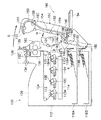
図1及び図2に示されるように、画像形成装置10には、第2搬送路46を開閉させる開閉装置50が配設されている。開閉装置50は、装置本体12に開閉可能に設けられた外側開閉部の一例としての開閉カバー52を備えている。   As shown in FIGS. 1 and 2, the image forming apparatus 10 is provided with an opening / closing device 50 that opens and closes the second conveyance path 46. The opening / closing device 50 includes an opening / closing cover 52 as an example of an outer opening / closing portion provided on the device main body 12 so as to be openable / closable.

この開閉カバー52は、装置下部に配置された第1ヒンジの一例としての開閉カバー用ヒンジ部54によって装置本体12に回転可能に支持されており、装置本体12側から装置外側へ(図2及び図3等における矢印A方向へ)回転して、開放位置へ傾倒することにより装置本体12に対して開放される。開閉カバー52は、図示しないストッパー等により、図3に示す開放位置で止まるように構成されている。また、開閉カバー52は、開放された状態から装置本体12側へ(図3等における矢印B方向へ)回転して、閉止位置へ縦立することにより装置本体12側へ閉止される(閉鎖又は閉じられる)。   The opening / closing cover 52 is rotatably supported by the apparatus main body 12 by an opening / closing cover hinge portion 54 as an example of a first hinge disposed at the lower part of the apparatus, and from the apparatus main body 12 side to the outside of the apparatus (see FIGS. 2 and 2). By rotating (in the direction of arrow A in FIG. 3 etc.) and tilting to the open position, the device main body 12 is opened. The open / close cover 52 is configured to stop at an open position shown in FIG. 3 by a stopper or the like (not shown). Further, the open / close cover 52 rotates from the opened state to the apparatus main body 12 side (in the direction of arrow B in FIG. 3 and the like) and is vertically closed to the close position to be closed to the apparatus main body 12 side (closed or closed). Closed).

また、開閉装置50は、開閉カバー52の内側(装置本体12と対向する側)に開閉可能に設けられた内側開閉部56を備えている。この内側開閉部56は、開閉カバー52の内側下部に配置された第2ヒンジの一例としての内側開閉部用ヒンジ部58によって開閉カバー52に回転可能に支持されており、開閉カバー52側から装置本体12側へ(図3及び図6等における矢印C方向へ)回転して、開放位置へ傾倒することにより開閉カバー52に対して装置本体12側へ開放される。内側開閉部56は、図示しないストッパー等により、図3に示す装置本体12側の開放位置で止まるように構成されている。   Further, the opening / closing device 50 includes an inner opening / closing portion 56 provided inside the opening / closing cover 52 (side facing the device main body 12) so as to be opened and closed. The inner opening / closing portion 56 is rotatably supported by the opening / closing cover 52 by an inner opening / closing portion hinge 58 as an example of a second hinge disposed at the inner lower portion of the opening / closing cover 52, and the device is opened from the opening / closing cover 52 side. By rotating to the main body 12 side (in the direction of arrow C in FIGS. 3 and 6 etc.) and tilting to the open position, the opening / closing cover 52 is opened to the apparatus main body 12 side. The inner opening / closing part 56 is configured to stop at an open position on the apparatus main body 12 side shown in FIG. 3 by a stopper or the like (not shown).

図2及び図3に示されるように、開閉装置50は、開閉カバー52が開放された状態で、内側開閉部用ヒンジ部58の支点(回転中心)が開閉カバー用ヒンジ部54の支点(回転中心)に対して装置本体12と反対側に配置されており、また、開閉カバー52を閉じた状態で、内側開閉部用ヒンジ部58の支点が開閉カバー用ヒンジ部54の支点よりも装置本体12側に配置されている。図3に示されるように、開閉カバー52を閉じる過程で内側開閉部用ヒンジ部58の支点が通る軌跡66は、開閉カバー用ヒンジ部54の支点の上方側で最大高さとなる頂点66Aを通り、開閉カバー52を閉じた状態で上記頂点66Aより下方側の閉止位置66Bに至るように構成されている。   As shown in FIGS. 2 and 3, in the opening / closing device 50, the fulcrum (rotation center) of the inner opening / closing part hinge 58 is the fulcrum (rotation) of the opening / closing cover hinge 54 with the opening / closing cover 52 opened. The fulcrum of the inner opening / closing part hinge 58 is more than the fulcrum of the opening / closing cover hinge 54 in a state in which the opening / closing cover 52 is closed. It is arranged on the 12 side. As shown in FIG. 3, the locus 66 through which the fulcrum of the inner opening / closing portion hinge portion 58 passes in the process of closing the opening / closing cover 52 passes through the apex 66 </ b> A having the maximum height above the fulcrum of the opening / closing cover hinge portion 54. In a state where the opening / closing cover 52 is closed, it is configured to reach a closing position 66B below the vertex 66A.

図2〜図4に示されるように、開閉カバー52は、装置本体12側(開閉カバー52の内側)に第2搬送路46の一方の搬送面を構成する凹状の湾曲面からなる外側搬送面52Aを備えている。内側開閉部56は、外側搬送面52Aに沿って配置された湾曲形状の板状部材からなり、内側開閉部56の外側(装置本体12と反対側)に第2搬送路46の他方の搬送面を構成する凸状の湾曲面からなる内側搬送面56Aを備えている。   As shown in FIGS. 2 to 4, the opening / closing cover 52 has an outer conveyance surface formed of a concave curved surface constituting one conveyance surface of the second conveyance path 46 on the apparatus main body 12 side (inside the opening / closing cover 52). 52A. The inner opening / closing part 56 is composed of a curved plate-like member disposed along the outer conveying surface 52A, and the other conveying surface of the second conveying path 46 on the outer side of the inner opening / closing part 56 (on the side opposite to the apparatus main body 12). An inner conveyance surface 56A made up of a convex curved surface is provided.

内側開閉部56の先端部(内側開閉部用ヒンジ部58と反対側)には、装置本体12と対向する面に、内側開閉部56を開放する際に把持される取っ手57が設けられている。取っ手57は、装置本体12側に突出する左右一対の側部57Aと、側部57Aに略水平に架け渡された板状部材57Bと、を備えている。そして、板状部材57Bを把持することで内側開閉部56が装置本体12側に開放される。板状部材57Bは、内側開閉部用ヒンジ部58側の開口が大きくなるように内側開閉部56の壁面に対して傾斜して設けられている。   A handle 57 that is gripped when the inner opening / closing part 56 is opened is provided on the front surface of the inner opening / closing part 56 (on the side opposite to the inner opening / closing part hinge 58). . The handle 57 includes a pair of left and right side portions 57A that protrude toward the apparatus main body 12 and a plate-like member 57B that extends substantially horizontally across the side portion 57A. The inner opening / closing part 56 is opened to the apparatus main body 12 side by gripping the plate-like member 57B. The plate-like member 57B is provided to be inclined with respect to the wall surface of the inner opening / closing part 56 so that the opening on the inner opening / closing part hinge part 58 side becomes large.

図5に示されるように、装置本体12は、開閉カバー52と対向する位置に、搬送ベルト26等が配設されたトランスユニット72を備えている。本実施形態では、トランスユニット72は装置本体12に対して着脱可能に取り付けられている。トランスユニット72の装置上方側の中央部には、内側開閉部56の取っ手57と対向する位置に、内側開閉部56側に突出する補助ガイド突起の一例としての一対のリブ74を備えている。トランスユニット72の上端部には、装置本体12側に後退するように上部傾斜面72Aが形成されており、一対のリブ74は、上部傾斜面72Aに上下方向に沿って略平行に配置されている。また、一対のリブ74の上端部の角部は円弧状に形成されている。   As shown in FIG. 5, the apparatus main body 12 includes a transformer unit 72 in which a transport belt 26 and the like are disposed at a position facing the opening / closing cover 52. In the present embodiment, the transformer unit 72 is detachably attached to the apparatus main body 12. A central portion of the transformer unit 72 on the upper side of the device is provided with a pair of ribs 74 as an example of auxiliary guide protrusions protruding toward the inner opening / closing portion 56 at a position facing the handle 57 of the inner opening / closing portion 56. An upper inclined surface 72A is formed at the upper end of the transformer unit 72 so as to recede toward the apparatus main body 12, and the pair of ribs 74 are disposed substantially parallel to the upper inclined surface 72A along the vertical direction. Yes. Moreover, the corner | angular part of the upper end part of a pair of rib 74 is formed in circular arc shape.

一対のリブ74は、内側開閉部56を装置本体12側に開放した状態で開閉カバー52を閉じるときに、内側開閉部56に設けられた取っ手57の板状部材57Bが接触して内側開閉部56をガイドすると共に、取っ手57がトランスユニット72の上端部に引っ掛からない方向(図7等における矢印D方向)に押されるように構成されている。   The pair of ribs 74 contact the plate member 57B of the handle 57 provided on the inner opening / closing portion 56 when the opening / closing cover 52 is closed with the inner opening / closing portion 56 opened to the apparatus main body 12 side. 56, and the handle 57 is configured to be pushed in a direction that does not catch on the upper end of the transformer unit 72 (in the direction of arrow D in FIG. 7 and the like).

図2及び図3に示されるように、装置本体12の上部におけるトランスユニット72の上方側には、定着装置40(図1参照)を構成する筐体76が設けられており、筐体76の上方側には、搬送される用紙Pをガイドするためのガイド部材78が設けられている。ガイド部材78の用紙搬送方向下流側の端部は、筐体76の外壁面より開閉カバー52側に突出するように設けられている。   As shown in FIGS. 2 and 3, a casing 76 constituting the fixing device 40 (see FIG. 1) is provided above the transformer unit 72 in the upper part of the apparatus main body 12. A guide member 78 for guiding the conveyed paper P is provided on the upper side. The end of the guide member 78 on the downstream side in the sheet conveyance direction is provided so as to protrude from the outer wall surface of the housing 76 toward the opening / closing cover 52.

図5に示されるように、トランスユニット72の幅方向両側には、内側開閉部56と対向する位置に、内側開閉部56側に突出するガイド突起の一例としての左右一対のガイド突起80が設けられている。ガイド突起80は、略十字状に形成されており、先端部よりもトランスユニット72側の根元部の幅が大きくなるように形成されている。図2及び図3等に示されるように、内側開閉部56の幅方向両側には、左右一対のガイド突起80と対向する位置に、トランスユニット72側に突出する左右一対の突出部60が設けられている。突出部60の下部側には、上部側がトランスユニット72側に突出するように傾斜する傾斜面が形成されている。   As shown in FIG. 5, a pair of left and right guide protrusions 80 as an example of guide protrusions protruding toward the inner opening / closing part 56 are provided on both sides in the width direction of the transformer unit 72 at positions facing the inner opening / closing part 56. It has been. The guide protrusion 80 is formed in a substantially cross shape, and is formed such that the width of the root portion on the transformer unit 72 side is larger than the tip portion. As shown in FIG. 2 and FIG. 3 and the like, a pair of left and right projecting portions 60 projecting toward the transformer unit 72 are provided on both sides in the width direction of the inner opening / closing portion 56 at positions facing the pair of left and right guide projections 80. It has been. On the lower side of the protrusion 60, an inclined surface is formed so that the upper side protrudes toward the transformer unit 72.

一対のガイド突起80は、内側開閉部56を装置本体12側に開放した状態で開閉カバー52を閉じるときに、内側開閉部56の板状部材57Bとトランスユニット72のリブ74との接触が外れた後に内側開閉部56の突出部60が接触することにより、内側開閉部56が開閉カバー52に近づく方向(内側開閉部56が開閉カバー52側に閉まる方向)に押されるように構成されている。言い換えると、内側開閉部56を装置本体12側に開放した状態で開閉カバー52を閉じるときに、ガイド突起80と内側開閉部56の突出部60とが接触する前に、内側開閉部56の板状部材57Bとトランスユニット72のリブ74とが接触し、板状部材57Bとリブ74との接触が外れた後に、内側開閉部56の突出部60とトランスユニット72のガイド突起80とが接触するように構成されている。   When the opening / closing cover 52 is closed with the inner opening / closing portion 56 open to the apparatus main body 12 side, the pair of guide protrusions 80 release the contact between the plate-like member 57B of the inner opening / closing portion 56 and the rib 74 of the transformer unit 72. After that, when the projecting portion 60 of the inner opening / closing portion 56 comes into contact, the inner opening / closing portion 56 is pushed in a direction approaching the opening / closing cover 52 (a direction in which the inner opening / closing portion 56 closes to the opening / closing cover 52 side). . In other words, when the opening / closing cover 52 is closed with the inner opening / closing portion 56 opened to the apparatus main body 12 side, the plate of the inner opening / closing portion 56 is brought into contact before the guide protrusion 80 and the protruding portion 60 of the inner opening / closing portion 56 contact each other. After the plate-like member 57B and the rib 74 of the transformer unit 72 are in contact with each other and the contact between the plate-like member 57B and the rib 74 is released, the protruding portion 60 of the inner opening / closing portion 56 and the guide protrusion 80 of the transformer unit 72 are in contact with each other. It is configured as follows.

図3及び図4等に示されるように、内側開閉部56の突出部60には、開閉カバー52を装置本体12側に閉じた状態でガイド突起80が嵌合されることにより、内側開閉部56が位置決めされる嵌合穴62が設けられている。嵌合穴62は、ガイド突起80の外形よりも若干大きく形成された略円形状の凹部から構成されている。   As shown in FIGS. 3 and 4 and the like, the protrusion 60 of the inner opening / closing portion 56 is fitted with a guide protrusion 80 in a state where the opening / closing cover 52 is closed to the apparatus main body 12 side. A fitting hole 62 for positioning 56 is provided. The fitting hole 62 is formed of a substantially circular recess formed slightly larger than the outer shape of the guide protrusion 80.

次に、本実施形態の作用について説明する。   Next, the operation of this embodiment will be described.

画像形成装置10において、前述の画像形成動作により第2搬送路46でジャム(紙詰まり)が発生した場合、詰まった用紙Pを除去するために開閉装置50を操作する。具体的には、操作者は、開閉カバー52を開閉カバー用ヒンジ部54を中心に矢印A方向へ回転して、開閉カバー52を装置本体12(トランスユニット72)に対して装置外側へ開放する。このとき、開閉カバー52に回転可能に支持された内側開閉部56も開閉カバー52と一体となって開放される(図3参照、なお、図3ではジャム時の用紙Pは省略されている)。図3に示される開放位置では、開閉カバー52は装置本体12に対して約90°開放されている。   In the image forming apparatus 10, when a jam (paper jam) occurs in the second transport path 46 by the above-described image forming operation, the opening / closing device 50 is operated to remove the jammed paper P. Specifically, the operator rotates the opening / closing cover 52 around the opening / closing cover hinge 54 in the direction of arrow A to open the opening / closing cover 52 to the outside of the apparatus with respect to the apparatus main body 12 (transformer unit 72). . At this time, the inner opening / closing part 56 rotatably supported by the opening / closing cover 52 is also opened integrally with the opening / closing cover 52 (see FIG. 3, the paper P at the time of jamming is omitted in FIG. 3). . In the open position shown in FIG. 3, the open / close cover 52 is opened about 90 ° with respect to the apparatus main body 12.

さらに、図6に示されるように、内側開閉部56を内側開閉部用ヒンジ部58を中心に矢印C方向へ回転して、内側開閉部56を開閉カバー52側から装置本体12側(トランスユニット72側)へ開放する。その際、内側開閉部56の取っ手57(図4参照)を把持することにより、内側開閉部56を開放する。内側開閉部56を開放した状態で、ジャム時の用紙Pを除去する。   Further, as shown in FIG. 6, the inner opening / closing portion 56 is rotated in the direction of arrow C around the inner opening / closing portion hinge 58, so that the inner opening / closing portion 56 is moved from the opening / closing cover 52 side to the device main body 12 side (transformer unit). 72 side). At that time, the inner opening / closing part 56 is opened by gripping the handle 57 (see FIG. 4) of the inner opening / closing part 56. With the inner opening / closing part 56 opened, the paper P at the time of jamming is removed.

その後、通常の操作では、内側開閉部56を装置本体12側から矢印Cと反対方向へ回転して内側開閉部56を開閉カバー52側に閉じ(図3参照)、さらに、開閉カバー52を矢印B方向に回転して装置本体12側へ閉じる。   Thereafter, in a normal operation, the inner opening / closing part 56 is rotated in the direction opposite to the arrow C from the apparatus main body 12 side to close the inner opening / closing part 56 to the opening / closing cover 52 side (see FIG. 3). Rotate in the B direction and close to the apparatus main body 12 side.

しかし、操作者によっては、内側開閉部56を装置本体12側へ開放した状態のまま、開閉カバー52を矢印B方向に回転して装置本体12側へ閉じる場合がある。開閉装置50では、内側開閉部用ヒンジ部58の支点が通る軌跡66(図3参照)は、開閉カバー52を閉じる動作に伴って徐々に上昇していき、開閉カバー用ヒンジ部54の支点の上方側で最大高さとなる頂点66Aを通り、開閉カバー52を閉じた状態で上記頂点66Aより下方側の閉止位置66Bに至る。その際、内側開閉部56及び開閉カバー52は以下のように動作する。   However, depending on the operator, the opening / closing cover 52 may be rotated in the direction of arrow B and closed to the apparatus main body 12 side with the inner opening / closing portion 56 opened to the apparatus main body 12 side. In the opening / closing device 50, the locus 66 (see FIG. 3) through which the fulcrum of the inner opening / closing portion hinge 58 passes gradually rises as the opening / closing cover 52 is closed. It passes through the apex 66A having the maximum height on the upper side, and reaches the closing position 66B on the lower side from the apex 66A with the open / close cover 52 closed. At that time, the inner opening / closing part 56 and the opening / closing cover 52 operate as follows.

図7に示されるように、開閉カバー52を矢印B方向に回転して装置本体12側(トランスユニット72側)へ閉じていくと(図7は、開閉カバー52を開放位置から装置本体12側へ約20°閉じた状態)、内側開閉部56の板状部材57Bがトランスユニット72のリブ74の縁部を滑りながら、矢印D方向へ持ち上がる。図8に示されるように、開閉カバー52を矢印B方向に更に回転して装置本体12側(トランスユニット72側)へ閉じていくと(図8は、開閉カバー52を開放位置から装置本体12側へ約40°閉じた状態)、内側開閉部56の板状部材57Bの下端部がトランスユニット72のリブ74の縁部を滑りながら、矢印D方向へ更に持ち上がる。これによって、内側開閉部56の取っ手57がトランスユニット72の上端部付近に引っ掛かることが回避される。   As shown in FIG. 7, when the opening / closing cover 52 is rotated in the direction of arrow B and closed to the apparatus main body 12 side (transformer unit 72 side) (FIG. 7 shows the opening / closing cover 52 from the open position to the apparatus main body 12 side. The plate-like member 57B of the inner opening / closing part 56 is lifted in the direction of arrow D while sliding on the edge of the rib 74 of the transformer unit 72. As shown in FIG. 8, when the opening / closing cover 52 is further rotated in the direction of arrow B and is closed to the apparatus main body 12 side (transformer unit 72 side) (FIG. 8 shows the opening / closing cover 52 from the open position to the apparatus main body 12. The bottom end of the plate-like member 57B of the inner opening / closing part 56 is further lifted in the direction of arrow D while sliding on the edge of the rib 74 of the transformer unit 72. This prevents the handle 57 of the inner opening / closing part 56 from being caught near the upper end of the transformer unit 72.

図9に示されるように、開閉カバー52を矢印B方向に更に回転して装置本体12側(トランスユニット72側)へ閉じていくと(図9は、開閉カバー52を開放位置から装置本体12側へ約60°閉じた状態)、内側開閉部56の板状部材57Bがトランスユニット72のリブ74を乗り越えることにより、内側開閉部56の板状部材57Bが持ち上がる方向が矢印D方向から矢印E方向に変わる。   As shown in FIG. 9, when the opening / closing cover 52 is further rotated in the direction of the arrow B and is closed to the apparatus main body 12 side (transformer unit 72 side) (FIG. 9 shows that the opening / closing cover 52 is moved from the open position to the apparatus main body 12 When the plate member 57B of the inner opening / closing portion 56 gets over the rib 74 of the transformer unit 72, the direction in which the plate member 57B of the inner opening / closing portion 56 is lifted is changed from the arrow D direction to the arrow E. Change direction.

図10に示されるように、開閉カバー52を矢印B方向に更に回転して装置本体12側(トランスユニット72側)へ閉じていくと(図10は、開閉カバー52を開放位置から装置本体12側へ約80°閉じた状態)、内側開閉部56の突出部60がトランスユニット72のガイド突起80を滑りながら、矢印F方向へ持ち上がる。すなわち、内側開閉部56とトランスユニット72の滑る場所が、板状部材57Bとリブ74から、突出部60とガイド突起80に変わり、内側開閉部56の板状部材57Bが持ち上がる方向も矢印E方向から矢印F方向に変わる。   As shown in FIG. 10, when the opening / closing cover 52 is further rotated in the direction of arrow B and closed to the apparatus main body 12 side (transformer unit 72 side) (FIG. 10 shows the opening / closing cover 52 from the open position to the apparatus main body 12. The projecting portion 60 of the inner opening / closing portion 56 is lifted in the direction of arrow F while sliding on the guide projection 80 of the transformer unit 72. That is, the place where the inner opening / closing portion 56 and the transformer unit 72 slide is changed from the plate-like member 57B and the rib 74 to the protruding portion 60 and the guide protrusion 80, and the direction in which the plate-like member 57B of the inner opening / closing portion 56 is lifted is also the direction of arrow E To the arrow F direction.

内側開閉部56の板状部材57Bが持ち上がる方向が矢印F方向に変わることにより、内側開閉部56の先端部と装置本体12のガイド部材78とが衝突する直前で、内側開閉部56の先端部と装置本体12のガイド部材78とが干渉することが回避される。これにより、内側開閉部用ヒンジ部58の支点が、開閉カバー用ヒンジ部54の支点の上方側で最大高さとなる頂点66Aを通り、開閉カバー52を閉じた状態で上記頂点66Aより下方側の閉止位置66Bに至る場合に、内側開閉部56の先端部が装置本体12に近づいても、内側開閉部56の先端部が装置本体12のガイド部材78等と干渉することが回避される。   When the direction in which the plate-like member 57B of the inner opening / closing part 56 is lifted is changed to the direction of arrow F, the tip of the inner opening / closing part 56 immediately before the tip of the inner opening / closing part 56 and the guide member 78 of the apparatus main body 12 collide. And the guide member 78 of the apparatus main body 12 are prevented from interfering with each other. Thus, the fulcrum of the inner opening / closing part hinge 58 passes through the vertex 66A having the maximum height above the fulcrum of the opening / closing cover hinge 54, and the opening / closing cover 52 is closed and the lower side of the vertex 66A. When reaching the closing position 66B, even if the tip of the inner opening / closing part 56 approaches the apparatus main body 12, the tip of the inner opening / closing part 56 is prevented from interfering with the guide member 78 and the like of the apparatus main body 12.

そして、図2に示されるように、開閉カバー52を矢印B方向に更に回転して、開閉カバー52を装置本体12側(トランスユニット72側)へ完全に閉じると(図2は、開閉カバー52を開放位置から装置本体12側へ約90°閉じた状態)、トランスユニット72のガイド突起80の先端部が内側開閉部56の突出部60に設けられた嵌合穴62に嵌り込み、内側開閉部56がトランスユニット72に対して位置決めされる。内側開閉部56を装置本体12側へ閉じたときに、ガイド突起80が内側開閉部56に対して邪魔になることはない。この状態で、開閉カバー52を装置本体12側(トランスユニット72側)へ閉じる操作が完了する。   Then, as shown in FIG. 2, when the opening / closing cover 52 is further rotated in the direction of arrow B and the opening / closing cover 52 is completely closed to the apparatus body 12 side (transformer unit 72 side) (FIG. 2 shows the opening / closing cover 52). Is closed about 90 ° from the open position to the apparatus main body 12 side), the tip of the guide projection 80 of the transformer unit 72 is fitted into the fitting hole 62 provided in the protruding portion 60 of the inner opening / closing portion 56, and the inner opening / closing is performed. The part 56 is positioned with respect to the transformer unit 72. When the inner opening / closing part 56 is closed toward the apparatus main body 12, the guide protrusion 80 does not interfere with the inner opening / closing part 56. In this state, the operation of closing the opening / closing cover 52 to the apparatus main body 12 side (transformer unit 72 side) is completed.

[第2実施形態]
次に、本発明の第2実施形態について説明する。なお、第1実施形態と同一の部材には同一の符号を付し、重複した説明を省略する。また、画像形成装置の全体構成は、第1実施形態と同一であるので、説明を省略する。
[Second Embodiment]
Next, a second embodiment of the present invention will be described. In addition, the same code | symbol is attached | subjected to the member same as 1st Embodiment, and the overlapping description is abbreviate | omitted. In addition, the overall configuration of the image forming apparatus is the same as that of the first embodiment, and thus description thereof is omitted.

図11に示されるように、第2実施形態に係る開閉装置90では、開閉カバー52の外側搬送面52Aの中間部に、内側開閉部56側に突出する位置決め用突起の一例としての左右一対の位置決め用突起92が設けられている。内側開閉部56の外側搬送面56Aには、開閉カバー52を装置本体12側へ閉じた状態で、位置決め用突起92が嵌合される位置決め用嵌合穴の一例としての左右一対の嵌合穴94が設けられている。嵌合穴94は、断面が略円形状に形成されており、内側開閉部56の突出部60を厚み方向に貫通するように設けられている。そして、嵌合穴94は、開閉カバー52を装置本体12側へ閉じた状態で、トランスユニット72のガイド突起80の先端部が内側開閉部56の嵌合穴94に嵌り込むように構成されている。   As shown in FIG. 11, in the opening / closing device 90 according to the second embodiment, a pair of left and right as an example of a positioning projection that protrudes toward the inner opening / closing portion 56 is provided at the intermediate portion of the outer conveyance surface 52A of the opening / closing cover 52. Positioning projections 92 are provided. A pair of left and right fitting holes as an example of a positioning fitting hole into which the positioning projection 92 is fitted in the outer conveyance surface 56A of the inner opening / closing portion 56 with the opening / closing cover 52 closed to the apparatus main body 12 side. 94 is provided. The fitting hole 94 has a substantially circular cross section, and is provided so as to penetrate the protruding portion 60 of the inner opening / closing portion 56 in the thickness direction. The fitting hole 94 is configured such that the tip end portion of the guide projection 80 of the transformer unit 72 fits into the fitting hole 94 of the inner opening / closing portion 56 with the opening / closing cover 52 closed to the apparatus main body 12 side. Yes.

次に、本実施形態の作用について説明する。   Next, the operation of this embodiment will be described.

図11に示されるように、開閉カバー52を装置本体12側(トランスユニット72側)へ閉じると、トランスユニット72のガイド突起80の先端部が内側開閉部56の内側から嵌合穴94に嵌り込み、内側開閉部56がトランスユニット72に対して位置決めされる。そのとき、開閉カバー52の位置決め用突起92が内側開閉部56の外側から嵌合穴94に嵌り込み、開閉カバー52が内側開閉部56に対して位置決めされる。   As shown in FIG. 11, when the opening / closing cover 52 is closed to the apparatus main body 12 side (transformer unit 72 side), the distal end portion of the guide projection 80 of the transformer unit 72 is fitted into the fitting hole 94 from the inside of the inner opening / closing portion 56. The inner opening / closing part 56 is positioned with respect to the transformer unit 72. At that time, the positioning projection 92 of the opening / closing cover 52 is fitted into the fitting hole 94 from the outside of the inner opening / closing portion 56, and the opening / closing cover 52 is positioned with respect to the inner opening / closing portion 56.

[第3実施形態]
次に、本発明の第3実施形態について説明する。なお、第1及び第2実施形態と同一の部材には同一の符号を付し、重複した説明を省略する。
[Third Embodiment]
Next, a third embodiment of the present invention will be described. In addition, the same code | symbol is attached | subjected to the member same as 1st and 2nd embodiment, and the overlapping description is abbreviate | omitted.

(画像形成装置の全体構成)
まず、第3実施形態に係る開閉装置を備えた画像形成装置の全体構成について、図12及び図13に基づき説明する。
(Overall configuration of image forming apparatus)
First, the overall configuration of an image forming apparatus including an opening / closing device according to the third embodiment will be described with reference to FIGS.

図12及び図13に示されるように、画像形成装置100は、装置本体102のほぼ中央部に、複数のローラに巻き掛けられた中間転写ベルト104を備えており、その中間転写ベルト104の下側走行辺に沿って4個の作像ユニット110Y、110C、110M、110Kを備えている。各作像ユニット110Y、110C、110M、110Kには感光体ドラム112が設けられている。この感光体ドラム112の周りには、帯電手段、現像装置、クリーニング手段等が配置され、さらに各感光体ドラム112に対向する位置において中間転写ベルト104の内側に一次転写ローラ108が設けられている。本実施形態では、4個の作像ユニット110Y、110C、110M、110Kは、図において左からマゼンタ、シアン、イエロー、ブラックの色順に配置されている。   As shown in FIGS. 12 and 13, the image forming apparatus 100 includes an intermediate transfer belt 104 wound around a plurality of rollers at a substantially central portion of the apparatus main body 102. Four image forming units 110Y, 110C, 110M, and 110K are provided along the side running side. Each image forming unit 110Y, 110C, 110M, and 110K is provided with a photosensitive drum 112. Around the photosensitive drum 112, a charging unit, a developing device, a cleaning unit, and the like are disposed, and a primary transfer roller 108 is provided inside the intermediate transfer belt 104 at a position facing each photosensitive drum 112. . In the present embodiment, the four image forming units 110Y, 110C, 110M, and 110K are arranged in the order of magenta, cyan, yellow, and black from the left in the drawing.

作像ユニット110Y、110C、110M、110Kの下方には光書き込み装置114が設けられている。光書き込み装置114は図示はしないがポリゴンミラーやミラー群等を有しており、光変調されたレーザ光を各色作像ユニットの感光体ドラム112の表面に照射する。   An optical writing device 114 is provided below the image forming units 110Y, 110C, 110M, and 110K. Although not shown, the optical writing device 114 has a polygon mirror, a group of mirrors, and the like, and irradiates the surface of the photosensitive drum 112 of each color image forming unit with light-modulated laser light.

装置本体102の下部には2段の給紙カセット116A、116Bが配設されており、各給紙カセットに対応する給紙手段118A、118Bが設けられている。給紙手段118A、118Bはそれぞれ、呼び出しローラ、供給ローラ及び分離ローラから構成されている。給紙手段118A、118Bによって給送される用紙P(記録媒体)を搬送するために、搬送ローラ対120、120が設けられている。上側の搬送ローラ対120の上方(用紙搬送方向の下流側)にはレジストローラ対122が設けられている。そのレジストローラ対122の上方には、二次転写ローラ124が、中間転写ベルト104が掛け渡されるローラの一つである転写対向ローラ106に対向して設けられている。   Two stages of paper feed cassettes 116A and 116B are disposed below the apparatus main body 102, and paper feed means 118A and 118B corresponding to the respective paper feed cassettes are provided. Each of the paper feeding units 118A and 118B includes a calling roller, a supply roller, and a separation roller. In order to transport the paper P (recording medium) fed by the paper feeding means 118A and 118B, a pair of transport rollers 120 and 120 are provided. A registration roller pair 122 is provided above the upper conveyance roller pair 120 (downstream in the sheet conveyance direction). A secondary transfer roller 124 is provided above the registration roller pair 122 so as to face the transfer counter roller 106 that is one of the rollers around which the intermediate transfer belt 104 is stretched.

二次転写ローラ124の上方側には定着装置126が設けられており、その定着装置126の上方には、用紙搬送方向を切り替えるための第1〜第3の切替爪128、129、130が配置されている。さらに、定着装置126の下流側には、搬送ローラ対132が配設されている。装置本体102の上面は排紙トレイ136として構成されており、その排紙トレイ136に用紙Pを排出するための排紙ローラ対134が、定着装置126の左上方に配設されている。   A fixing device 126 is provided above the secondary transfer roller 124. Above the fixing device 126, first to third switching claws 128, 129, and 130 for switching the paper transport direction are arranged. Has been. Further, a conveyance roller pair 132 is disposed on the downstream side of the fixing device 126. The upper surface of the apparatus main body 102 is configured as a paper discharge tray 136, and a paper discharge roller pair 134 for discharging the paper P to the paper discharge tray 136 is disposed on the upper left side of the fixing device 126.

両面ユニット150内には、スイッチバック搬送路152及び再給紙路154が形成されている。スイッチバック搬送路152には第1反転ローラ対156と第2反転ローラ対158が設けられている。第1反転ローラ対156と第2反転ローラ対158は、正逆回転可能に構成されている。そして、再給紙路154をほぼ三等分する位置に、搬送ローラ対160、162が配置されている。前述の第3切替爪130は、第1反転ローラ対156のすぐ隣で、スイッチバック搬送路152から再給紙路154への進入部に位置して配置されている。   A switchback conveyance path 152 and a refeed path 154 are formed in the duplex unit 150. The switchback conveyance path 152 is provided with a first reverse roller pair 156 and a second reverse roller pair 158. The first reverse roller pair 156 and the second reverse roller pair 158 are configured to be able to rotate forward and backward. A pair of conveyance rollers 160 and 162 are arranged at a position where the refeed path 154 is divided into approximately three equal parts. The above-described third switching claw 130 is disposed immediately next to the first reversing roller pair 156 and located at the entry portion from the switchback conveyance path 152 to the refeed path 154.

両面ユニット150の側面には手差しトレイ164が設けられている。この手差しトレイ164から用紙Pを給紙するために、呼び出しローラ、供給ローラ及び分離ローラからなる給紙手段166が設けられている。その給紙手段166の側方における装置内側に位置するように再給紙ローラ168が配設されている。再給紙ローラ168の上下両側には従動ローラがそれぞれ圧接されている。この再給紙ローラ168は正逆回転可能に構成されており、再給紙路154から用紙Pを再給紙する場合は図中反時計回りに回転駆動され、手差しトレイ164から用紙Pを給紙する場合は図中時計回りに回転駆動される。   A manual feed tray 164 is provided on the side surface of the duplex unit 150. In order to feed the sheet P from the manual feed tray 164, a sheet feeding unit 166 including a calling roller, a supply roller, and a separation roller is provided. A refeed roller 168 is disposed so as to be located inside the apparatus at the side of the paper feed means 166. The driven rollers are in pressure contact with the upper and lower sides of the refeed roller 168, respectively. The re-feed roller 168 is configured to be able to rotate forward and reverse. When the paper P is re-feeded from the re-feed path 154, the re-feed roller 168 is driven to rotate counterclockwise in the drawing, and the paper P is fed from the manual feed tray 164. In the case of paper, it is rotated clockwise in the figure.

次に、上記のように構成された画像形成装置100における画像形成動作について説明する。   Next, an image forming operation in the image forming apparatus 100 configured as described above will be described.

上記作像ユニット110Y、110C、110M、110Kの感光体ドラム112が図中時計方向に回転駆動され、その感光体ドラム112の表面が帯電手段によって所定の極性に一様に帯電される。帯電された感光体表面には、光書き込み装置114からレーザ光が照射され、これによって感光体ドラム112表面に静電潜像が形成される。このとき、各感光体ドラム112に露光される画像情報は所望のフルカラー画像をイエロー、マゼンタ、シアン、及びブラックの色情報に分解した単色の画像情報であり、このように形成された静電潜像に現像装置から各色トナーが付与され、トナー像として可視化される。   The photosensitive drums 112 of the image forming units 110Y, 110C, 110M, and 110K are rotationally driven in the clockwise direction in the figure, and the surface of the photosensitive drum 112 is uniformly charged to a predetermined polarity by a charging unit. The charged photoconductor surface is irradiated with laser light from the optical writing device 114, whereby an electrostatic latent image is formed on the photoconductor drum 112 surface. At this time, the image information exposed to each photosensitive drum 112 is single-color image information obtained by separating a desired full-color image into color information of yellow, magenta, cyan, and black, and the electrostatic latent image formed in this way. Each color toner is applied to the image from the developing device and visualized as a toner image.

また、中間転写ベルト104が矢印で示すように図中反時計回りに走行駆動され、各作像ユニット110Y、110C、110M、110Kにおいて一次転写ローラ108の作用により感光体ドラム112から中間転写ベルト104に各色トナー像が順次重ね転写される。   Further, the intermediate transfer belt 104 is driven to run counterclockwise in the drawing as indicated by an arrow, and the intermediate transfer belt 104 is moved from the photosensitive drum 112 by the action of the primary transfer roller 108 in each of the image forming units 110Y, 110C, 110M, and 110K. Each color toner image is sequentially superimposed and transferred.

一方、給紙カセット116A、116Bあるいは手差しトレイ164から用紙Pが選択的に給送され、レジストローラ対122によって、中間転写ベルト104上に担持されたトナー像とのタイミングを取って二次転写位置に向けて送出され、二次転写ローラ124により中間転写ベルト104表面のトナー像が用紙P上に一括して転写される。トナー像を転写された用紙Pは、定着装置126を通過することにより、用紙Pにトナー像が定着される。用紙Pは、排紙ローラ対134により装置本体102の上部に構成された排紙トレイ136に排出される。   On the other hand, the paper P is selectively fed from the paper feed cassettes 116A and 116B or the manual feed tray 164, and the secondary transfer position is timed by the registration roller pair 122 with the toner image carried on the intermediate transfer belt 104. The toner images on the surface of the intermediate transfer belt 104 are collectively transferred onto the paper P by the secondary transfer roller 124. The paper P to which the toner image has been transferred passes through the fixing device 126, whereby the toner image is fixed on the paper P. The paper P is discharged by a paper discharge roller pair 134 to a paper discharge tray 136 formed on the upper part of the apparatus main body 102.

用紙両面にプリントを行う場合は、用紙片面にトナー像を定着した用紙を、第1〜第3切替爪128,129、130を切り替えて第1及び第2反転ローラ対156、158を回転させることにより、スイッチバック搬送路152内に進入させる。さらに、第1及び第2反転ローラ対156、158を逆方向に回転させて用紙Pを反転させ、用紙Pを再給紙路154へと送り込む。再給紙路154内を用紙は搬送ローラ対160、162により搬送され、さらに再給紙ローラ168によりレジストローラ対122へと送られる。そして、用紙Pの裏面に中間転写ベルト104からトナー像が転写され、その裏面画像を定着装置126で定着することにより、用紙Pの裏面に画像が形成される。   When printing on both sides of the sheet, the first and second reversing roller pairs 156, 158 are rotated by switching the first to third switching claws 128, 129, 130 on the sheet having the toner image fixed on one side of the sheet. To enter the switchback conveyance path 152. Further, the first and second reversing roller pairs 156 and 158 are rotated in the reverse direction to reverse the paper P, and the paper P is fed into the refeed path 154. The sheet is transported in the refeed path 154 by the transport roller pair 160 and 162, and further sent to the registration roller pair 122 by the refeed roller 168. Then, the toner image is transferred from the intermediate transfer belt 104 to the back surface of the paper P, and the back image is fixed by the fixing device 126, whereby an image is formed on the back surface of the paper P.

(開閉装置)
次に、第3実施形態の画像形成装置100に備えられた開閉装置について説明する。
(Opening and closing device)
Next, the opening / closing device provided in the image forming apparatus 100 of the third embodiment will be described.

図13に示されるように、画像形成装置100には、再給紙路154を開閉させる開閉装置180が配設されている。開閉装置180は、装置本体102に開閉可能に設けられた外側開閉部の一例としての前述の両面ユニット150を備えている。   As shown in FIG. 13, the image forming apparatus 100 is provided with an opening / closing device 180 that opens and closes the refeed path 154. The opening / closing device 180 includes the above-described double-sided unit 150 as an example of an outer opening / closing portion provided in the device main body 102 so as to be openable / closable.

この両面ユニット150は、装置下部に配置された第1ヒンジの一例としてのヒンジ部182によって装置本体102に回転可能に支持されており、装置本体102側から装置外側へ(図13における矢印G方向へ)回転して開放位置へ傾倒することにより装置本体102に対して開放される。なお、両面ユニット150は図示しないリンク機構により装置本体102に支持され、図13に示す開放位置で止まるようになっている。   The duplex unit 150 is rotatably supported by the apparatus main body 102 by a hinge portion 182 as an example of a first hinge disposed at the lower part of the apparatus, and moves from the apparatus main body 102 side to the outside of the apparatus (in the direction of arrow G in FIG. 13). F) It is opened with respect to the apparatus main body 102 by rotating and tilting to the open position. The duplex unit 150 is supported by the apparatus main body 102 by a link mechanism (not shown), and stops at the open position shown in FIG.

また、開閉装置180は、両面ユニット150の内側(装置本体102と対向する側)に開閉可能に設けられた内側開閉部184を備えている。この内側開閉部184は、両面ユニット150の内側下部に配置された第2ヒンジの一例としてのヒンジ部186によって両面ユニット150に回転可能に支持されており、両面ユニット150側から装置本体102側へ(図13における矢印H方向へ)回転して、開放位置へ傾倒することにより両面ユニット150に対して装置本体102側へ開放される。内側開閉部184には、二次転写ローラ124、レジストローラ対122の片方の従動側ローラ、搬送ローラ対162の片方の従動側ローラ、再給紙ローラ168の片方の従動側ローラが配設されている。   The opening / closing device 180 includes an inner opening / closing portion 184 that can be opened and closed inside the double-sided unit 150 (on the side facing the device main body 102). The inner opening / closing part 184 is rotatably supported by the double-sided unit 150 by a hinge part 186 as an example of a second hinge disposed at the lower inner side of the double-sided unit 150, and from the double-sided unit 150 side to the apparatus main body 102 side. By rotating (in the direction of arrow H in FIG. 13) and tilting to the open position, the double-sided unit 150 is opened to the apparatus main body 102 side. The inner opening / closing unit 184 includes a secondary transfer roller 124, one driven roller of the registration roller pair 122, one driven roller of the conveyance roller pair 162, and one driven roller of the refeed roller 168. ing.

開閉装置180では、両面ユニット150を装置本体102に対して装置外側に開放した状態では、ヒンジ部182に対して内側開閉部184のヒンジ部186が装置外側に位置しており、両面ユニット150を装置本体102側へ閉じた状態では、ヒンジ部182の上方側に内側開閉部184のヒンジ部186が位置するように構成されている。   In the opening / closing device 180, the hinge unit 186 of the inner opening / closing unit 184 is positioned outside the device with respect to the hinge unit 182 in a state where the duplex unit 150 is opened to the outside of the device main body 102. When closed to the apparatus main body 102 side, the hinge part 186 of the inner opening / closing part 184 is positioned above the hinge part 182.

装置本体102の幅方向両側には、内側開閉部184と対向する位置に、内側開閉部184側に突出するガイド突起の一例としての左右一対のガイド突起190が設けられている。ガイド突起190は、先端部が尖状に突出するように形成されている。内側開閉部184の幅方向両側には、ガイド突起190と対向する位置に、内側開閉部184を装置本体102側に開放した状態で両面ユニット150を閉じるときに、ガイド突起190に接触可能な壁面184Aが形成されている。本実施形態では、壁面184Aは、上部側が下部側に対して装置本体102側に突出するような傾斜面となっている。ガイド突起190は、内側開閉部184を装置本体102側に開放した状態で両面ユニット150を閉じるときに、内側開閉部184の壁面184Aが接触して内側開閉部184がガイドされると共に、内側開閉部184が両面ユニット150に近づく方向(内側開閉部184が両面ユニット150側へ閉まる方向)に押されるように構成されている。   On both sides in the width direction of the apparatus main body 102, a pair of left and right guide protrusions 190 as an example of guide protrusions protruding toward the inner opening / closing part 184 are provided at positions facing the inner opening / closing part 184. The guide protrusion 190 is formed so that the tip portion protrudes in a sharp shape. Wall surfaces that can come into contact with the guide protrusion 190 when the duplex unit 150 is closed on both sides in the width direction of the inner opening / closing section 184 at a position facing the guide protrusion 190 with the inner opening / closing section 184 opened to the apparatus body 102 side. 184A is formed. In the present embodiment, the wall surface 184A is an inclined surface such that the upper side protrudes toward the apparatus main body 102 with respect to the lower side. When the double-sided unit 150 is closed with the inner opening / closing part 184 open to the apparatus main body 102 side, the guide protrusion 190 contacts the wall surface 184A of the inner opening / closing part 184 to guide the inner opening / closing part 184 and The unit 184 is configured to be pushed in a direction approaching the duplex unit 150 (a direction in which the inner opening / closing unit 184 is closed toward the duplex unit 150).

内側開閉部184の壁面184Aには、両面ユニット150を閉じた状態でガイド突起190が嵌合されて内側開閉部184が位置決めされる嵌合穴の一例としての左右一対の嵌合穴192が設けられている。嵌合穴192は、ガイド突起190の外形よりも若干大きく形成された凹部から構成されている。再給紙路154は、その一方側(装置内側)を内側開閉部184の搬送面で構成され、反対側(装置外側)を両面ユニット150の搬送面で構成され、両面ユニット150を装置本体102側へ閉じたときに再給紙路154が形成される。   The wall surface 184A of the inner opening / closing part 184 is provided with a pair of left and right fitting holes 192 as an example of a fitting hole in which the guide protrusion 190 is fitted and the inner opening / closing part 184 is positioned with the duplex unit 150 closed. It has been. The fitting hole 192 is constituted by a recess formed slightly larger than the outer shape of the guide protrusion 190. The re-feed path 154 has one side (inner side of the apparatus) constituted by the conveying surface of the inner opening / closing part 184, and the other side (outside of the apparatus) constituted by the conveying surface of the duplex unit 150. When closed to the side, a refeed path 154 is formed.

次に、本実施形態の作用について説明する。   Next, the operation of this embodiment will be described.

画像形成装置100において、前述の画像形成動作により再給紙路154でジャム(紙詰まり)が発生した場合、両面ユニット150を図13中に示す矢印G方向に回転して装置外側へ開放する。このとき、両面ユニット150に回転可能に支持された内側開閉部184も両面ユニット150と一体となって開放される。さらに、内側開閉部184を図13中に示す矢印H方向へ回転して両面ユニット150側から装置本体102側へ開放する(図13ではジャム時の用紙Pは省略されている)。この状態で、ジャム時の用紙Pを除去する。   In the image forming apparatus 100, when a jam (paper jam) occurs in the refeed path 154 due to the above-described image forming operation, the duplex unit 150 is rotated in the direction of arrow G shown in FIG. At this time, the inner opening / closing part 184 that is rotatably supported by the duplex unit 150 is also opened integrally with the duplex unit 150. Further, the inner opening / closing part 184 is rotated in the direction of arrow H shown in FIG. 13 to open from the duplex unit 150 side to the apparatus main body 102 side (in FIG. 13, the paper P at the time of jamming is omitted). In this state, the jammed paper P is removed.

その後、操作者によっては、内側開閉部184を装置本体102側へ開放した状態のまま、両面ユニット150を矢印Gと反対方向に回転して装置本体102側へ閉じる場合がある。この場合、両面ユニット150を装置本体102側へ閉じていくと、内側開閉部184の壁面184Aが装置本体102のガイド突起190を滑りながら、両面ユニット150側へ持ち上がる(内側開閉部184が両面ユニット150側へ押される)。内側開閉部184が両面ユニット150側へ持ち上がることにより、内側開閉部184の中間部付近が装置本体102の中間転写ベルト104や搬送路のガイド面と干渉しない。   Thereafter, depending on the operator, the duplex unit 150 may be rotated in the direction opposite to the arrow G and closed to the apparatus main body 102 side while the inner opening / closing part 184 is opened to the apparatus main body 102 side. In this case, when the double-sided unit 150 is closed to the apparatus main body 102 side, the wall surface 184A of the inner opening / closing part 184 is lifted to the double-sided unit 150 side while sliding the guide projection 190 of the apparatus main body 102 (the inner opening / closing part 184 is 150 side). By lifting the inner opening / closing part 184 toward the duplex unit 150, the vicinity of the middle part of the inner opening / closing part 184 does not interfere with the intermediate transfer belt 104 of the apparatus main body 102 and the guide surface of the conveyance path.

そして、図12に示されるように、両面ユニット150を更に回転して装置本体102側へ閉じると、装置本体102のガイド突起190の先端部が内側開閉部184の壁面184Aに設けられた嵌合穴192に嵌り込み、内側開閉部56が装置本体102に対して位置決めされる。この状態で、両面ユニット150を装置本体102側へ閉じる操作が完了する。   Then, as shown in FIG. 12, when the duplex unit 150 is further rotated and closed to the apparatus main body 102 side, the tip of the guide projection 190 of the apparatus main body 102 is fitted to the wall surface 184 </ b> A of the inner opening / closing part 184. The inner opening / closing portion 56 is positioned with respect to the apparatus main body 102 by being fitted into the hole 192. In this state, the operation for closing the duplex unit 150 toward the apparatus main body 102 is completed.

[上記実施形態の補足説明]
(1)第1及び第2実施形態では、トランスユニット72が装置本体12に対して着脱可能に設けられているが、トランスユニット72を装置本体12に一体に構成してもよい。すなわち、本発明の「装置本体」には、装置本体に一体に設けられた部材のほか、装置本体に着脱可能に設けられたユニット等を含む。
[Supplementary explanation of the above embodiment]
(1) In the first and second embodiments, the transformer unit 72 is detachably provided to the apparatus main body 12, but the transformer unit 72 may be configured integrally with the apparatus main body 12. That is, the “apparatus main body” of the present invention includes a unit and the like that are detachably provided on the apparatus main body in addition to members provided integrally with the apparatus main body.

(2)第1〜第3実施形態では、装置本体にガイド突起80、190を設けたが、これらに限定されず、内側開閉部、又は装置本体と内側開閉部の両方にガイド突起を設けてもよい。すなわち、装置本体及び内側開閉部の少なくとも一方にガイド突起を設ける構成であればよい。また、ガイド突起80、190の形状や位置も上記実施形態に限定されず、他の構成でもよい。   (2) In the first to third embodiments, the guide protrusions 80 and 190 are provided on the apparatus main body. However, the present invention is not limited thereto, and guide protrusions are provided on the inner opening / closing part or both the apparatus main body and the inner opening / closing part. Also good. That is, any structure may be used as long as the guide protrusion is provided on at least one of the apparatus main body and the inner opening / closing part. Further, the shapes and positions of the guide protrusions 80 and 190 are not limited to the above embodiment, and other configurations may be used.

(3)第1〜第3実施形態では、内側開閉部にガイド突起80、190が嵌合される位置決め用の嵌合穴62、92、192を設けたが、これらに限定されず、内側開閉部にガイド突起を設けると共に、装置本体に内側開閉部を位置決めするための嵌合穴を設けてもよい。すなわち、装置本体及び内側開閉部の一方にガイド突起を設け、装置本体及び内側開閉部の他方に、開閉カバー(外側開閉部)を閉じた状態でガイド突起が嵌合される嵌合穴を設ける構成であればよい。また、嵌合穴62、92、192の形状は上記実施形態に限定されず、他の構成でもよい。   (3) In the first to third embodiments, the fitting holes 62, 92, and 192 for positioning into which the guide protrusions 80 and 190 are fitted are provided in the inner opening and closing part. A guide protrusion may be provided on the part, and a fitting hole for positioning the inner opening / closing part may be provided on the apparatus main body. That is, a guide protrusion is provided on one of the apparatus main body and the inner opening / closing part, and a fitting hole is provided on the other of the apparatus main body and the inner opening / closing part so that the guide protrusion is fitted with the opening / closing cover (outer opening / closing part) closed. Any configuration may be used. Further, the shapes of the fitting holes 62, 92, and 192 are not limited to the above embodiment, and other configurations may be used.

(4)第1及び第2実施形態では、装置本体に補助ガイド突起の一例としてのリブ74を設けたが、これらに限定されず、内側開閉部、又は装置本体と内側開閉部の両方に補助ガイド突起を設けてもよい。すなわち、装置本体及び内側開閉部の少なくとも一方に補助ガイド突起を設ける構成であればよい。また、補助ガイド突起の形状や位置も上記実施形態に限定されず、他の構成でもよい。   (4) In the first and second embodiments, the apparatus main body is provided with the rib 74 as an example of the auxiliary guide protrusion, but the present invention is not limited thereto, and the auxiliary opening is provided to the inner opening / closing section or both the apparatus main body and the inner opening / closing section. Guide protrusions may be provided. That is, the auxiliary guide protrusion may be provided on at least one of the apparatus main body and the inner opening / closing part. Further, the shape and position of the auxiliary guide protrusion are not limited to the above embodiment, and other configurations may be used.

(5)第2実施形態では、開閉カバー52に位置決め用突起92を設け、内側開閉部56に位置決め用突起92が嵌合される位置決め用嵌合穴の一例としての嵌合穴94を設けたが、これに限定されず、開閉カバー(外側開閉部)に位置決め用嵌合穴を設けると共に、内側開閉部に位置決め用突起を設けてもよい。すなわち、内側開閉部及び外側開閉部の一方に位置決め用突起を設け、内側開閉部及び外側開閉部の他方に、外側開閉部を装置本体側へ閉じた状態で位置決め用突起が嵌合される位置決め用嵌合穴を設ける構成であればよい。また、位置決め用突起及び位置決め用嵌合穴の形状や位置も上記実施形態に限定されず、他の構成でもよい。   (5) In the second embodiment, the positioning projection 92 is provided on the opening / closing cover 52, and the fitting hole 94 as an example of the positioning fitting hole in which the positioning projection 92 is fitted is provided on the inner opening / closing portion 56. However, the present invention is not limited to this, and a positioning fitting hole may be provided in the opening / closing cover (outer opening / closing portion), and a positioning protrusion may be provided in the inner opening / closing portion. That is, a positioning protrusion is provided on one of the inner opening / closing part and the outer opening / closing part, and the positioning protrusion is fitted to the other of the inner opening / closing part and the outer opening / closing part with the outer opening / closing part closed to the apparatus body side. Any configuration may be used as long as a fitting hole is provided. Further, the shapes and positions of the positioning protrusions and the positioning fitting holes are not limited to the above embodiment, and other configurations may be used.

(6)なお、本発明は、上記の実施形態に限るものではなく、種々の変形、変更、改良が可能である。   (6) The present invention is not limited to the above embodiment, and various modifications, changes, and improvements can be made.

本発明の第1実施形態に係る画像形成装置を示す概略構成図である。1 is a schematic configuration diagram illustrating an image forming apparatus according to a first embodiment of the present invention. 第1実施形態に係る画像形成装置に用いられる開閉装置を示す構成図である。1 is a configuration diagram illustrating an opening / closing device used in an image forming apparatus according to a first embodiment. 第1実施形態に係る開閉装置において、開閉カバーを開放した状態を示す構成図である。It is a block diagram which shows the state which open | released the opening / closing cover in the opening / closing apparatus which concerns on 1st Embodiment. 第1実施形態に係る開閉装置に用いられる開閉カバー及び内側開閉部を示す斜視図である。It is a perspective view which shows the opening / closing cover and inner side opening / closing part which are used for the opening / closing apparatus which concerns on 1st Embodiment. 第1実施形態に係る開閉装置に用いられる装置本体に設けられたトランスユニットを示す斜視図である。It is a perspective view which shows the transformer unit provided in the apparatus main body used for the opening / closing apparatus which concerns on 1st Embodiment. 第1実施形態に係る開閉装置において、ジャム(紙詰まり)時に開閉カバーを開放し、内側開閉部を装置本体側に開放した状態を示す構成図である。In the opening / closing apparatus according to the first embodiment, the opening / closing cover is opened in the event of a jam (paper jam), and the inner opening / closing part is opened to the apparatus main body side. 第1実施形態に係る開閉装置において、内側開閉部を装置本体側に開放した状態で開閉カバーを閉じる過程で、内側開閉部の板状部材がリブに接触した状態を示す構成図である。In the opening / closing apparatus which concerns on 1st Embodiment, it is a block diagram which shows the state which the plate-shaped member of the inner side opening / closing part contacted the rib in the process of closing an opening / closing cover in the state which opened the inner side opening / closing part to the apparatus main body side. 第1実施形態に係る開閉装置において、内側開閉部を装置本体側に開放した状態で開閉カバーを閉じる過程で、内側開閉部の板状部材がリブを滑りながら移動する状態を示す構成図である。In the opening / closing apparatus which concerns on 1st Embodiment, it is a block diagram which shows the state which the plate-shaped member of an inner side opening / closing part moves, sliding a rib in the process of closing an opening / closing cover in the state which opened the inner side opening / closing part to the apparatus main body side. . 第1実施形態に係る開閉装置において、内側開閉部を装置本体側に開放した状態で開閉カバーを閉じる過程で、内側開閉部の板状部材とリブとの接触が外れた状態を示す構成図である。In the opening / closing apparatus which concerns on 1st Embodiment, in the process which closes an opening / closing cover in the state which opened the inner side opening / closing part to the apparatus main body side, it is a block diagram which shows the state which the contact between the plate-shaped member of the inner opening / closing part and the rib removed. is there. 第1実施形態に係る開閉装置において、内側開閉部を装置本体側に開放した状態で開閉カバーを閉じる過程で、内側開閉部の突出部がガイド突起を滑りながら移動する状態を示す構成図である。In the opening / closing apparatus which concerns on 1st Embodiment, it is a block diagram which shows the state which the protrusion part of an inner side opening / closing part moves, sliding a guide protrusion in the process of closing an opening / closing cover in the state which opened the inner side opening / closing part to the apparatus main body side. . 第2実施形態に係る画像形成装置に用いられる開閉装置を示す構成図である。It is a block diagram which shows the opening / closing apparatus used for the image forming apparatus which concerns on 2nd Embodiment. 第3実施形態に係る画像形成装置に用いられる開閉装置を示す構成図である。It is a block diagram which shows the opening / closing apparatus used for the image forming apparatus which concerns on 3rd Embodiment. 第3実施形態に係る画像形成装置において、両面ユニットを装置外側に開放すると共に、内側開閉部を装置本体側に開放した状態を示す構成図である。In the image forming apparatus according to the third embodiment, the double-side unit is opened to the outside of the apparatus, and the inner opening / closing part is opened to the apparatus main body side.

符号の説明Explanation of symbols

10 画像形成装置
12 装置本体
46 第2搬送路(記録媒体搬送路)
50 開閉装置
52 開閉カバー(外側開閉部)
54 開閉カバー用ヒンジ部(第1ヒンジ)
56 内側開閉部
58 内側開閉部用ヒンジ部(第2ヒンジ)
62 嵌合穴
66 軌跡
66A 頂点
66B 閉止位置(外側開閉部を閉じた状態の第2ヒンジの支点の位置)
72 トランスユニット(装置本体)
74 リブ(補助ガイド突起)
80 ガイド突起
90 開閉装置
92 位置決め用突起
94 嵌合穴(位置決め用嵌合穴)
100 画像形成装置
102 装置本体
150 両面ユニット(外側開閉部)
154 再給紙路(記録媒体搬送路)
180 開閉装置
182 ヒンジ部(第1ヒンジ)
184 内側開閉部
186 ヒンジ部(第2ヒンジ)
190 ガイド突起
192 嵌合穴
P 用紙(記録媒体)
DESCRIPTION OF SYMBOLS 10 Image forming apparatus 12 Apparatus main body 46 2nd conveyance path (recording medium conveyance path)
50 Opening / closing device 52 Opening / closing cover (outer opening / closing part)
54 Opening / closing cover hinge (first hinge)
56 Inner opening / closing part 58 Inner opening / closing part hinge part (second hinge)
62 Fitting hole 66 Trajectory 66A Vertex 66B Closed position (the position of the fulcrum of the second hinge with the outer opening / closing part closed)
72 Transformer unit (main unit)
74 Ribs (Auxiliary guide protrusions)
80 Guide protrusion 90 Opening and closing device 92 Positioning protrusion 94 Fitting hole (positioning fitting hole)
DESCRIPTION OF SYMBOLS 100 Image forming apparatus 102 Apparatus main body 150 Duplex unit (outer opening / closing part)
154 Re-feed path (recording medium transport path)
180 Opening / closing device 182 Hinge part (first hinge)
184 Inner opening / closing part 186 Hinge part (second hinge)
190 Guide protrusion 192 Fitting hole P Paper (recording medium)

Claims (8)

装置本体の下方に設けられた第1ヒンジを中心として開閉される外側開閉部と、
前記外側開閉部の下方に設けられた第2ヒンジを中心として開閉され、かつ、前記外側開閉部側から前記装置本体側に開放される内側開閉部と、
前記装置本体及び前記内側開閉部の少なくとも一方に設けられ、前記内側開閉部を開放した状態で前記外側開閉部を閉じるときに、前記内側開閉部が前記外側開閉部に近づく方向に押されて前記内側開閉部が前記装置本体と干渉しないようにガイドすると共に、前記外側開閉部を閉じた状態ではガイドする状態から外れるように配置されたガイド突起と、
を有することを特徴とする開閉装置。
An outer opening / closing portion that is opened and closed around a first hinge provided below the apparatus body;
An inner opening / closing part that is opened / closed around a second hinge provided below the outer opening / closing part, and that is opened from the outer opening / closing part side to the apparatus main body side;
Provided in at least one of the apparatus main body and the inner opening / closing part, and when the outer opening / closing part is closed in a state where the inner opening / closing part is opened, the inner opening / closing part is pushed in a direction approaching the outer opening / closing part. A guide protrusion arranged to guide the inner opening / closing part so as not to interfere with the apparatus main body, and to deviate from the guiding state when the outer opening / closing part is closed;
A switchgear characterized by comprising:
前記内側開閉部を開放した状態で前記外側開閉部を閉じるときに、前記内側開閉部の先端部が前記装置本体に衝突する前に前記内側開閉部が前記ガイド突起により押されて前記内側開閉部の先端部と前記装置本体との干渉が回避されるように構成されていることを特徴とする請求項1に記載の開閉装置。   When the outer opening / closing part is closed with the inner opening / closing part opened, the inner opening / closing part is pushed by the guide protrusion before the tip of the inner opening / closing part collides with the apparatus main body. The opening / closing device according to claim 1, wherein interference between the distal end of the device and the device main body is avoided. 前記外側開閉部が開放された状態で、前記第2ヒンジの支点が前記第1ヒンジの支点に対して前記装置本体と反対側に配置されると共に、前記外側開閉部を閉じた状態で、前記第2ヒンジの支点が前記第1ヒンジの支点よりも前記装置本体側に配置されており、
前記外側開閉部を閉じる過程で、前記第2ヒンジの支点の軌跡が、前記第1ヒンジの支点の上方側で最大高さとなる頂点を通り、前記外側開閉部を閉じた状態で前記頂点より下方側に位置するように設定されていることを特徴とする請求項2に記載の開閉装置。
The fulcrum of the second hinge is disposed on the opposite side of the apparatus main body with respect to the fulcrum of the first hinge in a state where the outer opening / closing part is opened, and the outer opening / closing part is closed, The fulcrum of the second hinge is disposed closer to the apparatus body than the fulcrum of the first hinge,
In the process of closing the outer opening / closing part, the locus of the fulcrum of the second hinge passes through the vertex having the maximum height above the fulcrum of the first hinge, and is lower than the vertex with the outer opening / closing part closed. The switchgear according to claim 2, wherein the switchgear is set to be located on a side.
前記装置本体及び前記内側開閉部の少なくとも一方に設けられ、前記内側開閉部を開放した状態で前記外側開閉部を閉じるときに、前記ガイド突起が前記装置本体及び前記内側開閉部の少なくとも一方と接触する前に、前記内側開閉部の一部が前記装置本体と干渉しないようにガイドする補助ガイド突起を有することを特徴とする請求項2又は請求項3に記載の開閉装置。   Provided on at least one of the apparatus main body and the inner opening / closing part, and when the outer opening / closing part is closed with the inner opening / closing part opened, the guide projection contacts at least one of the apparatus main body and the inner opening / closing part. The opening / closing apparatus according to claim 2 or 3, further comprising an auxiliary guide protrusion that guides a part of the inner opening / closing part so as not to interfere with the apparatus main body. 前記装置本体及び前記内側開閉部の一方に前記ガイド突起が設けられ、
前記装置本体及び前記内側開閉部の他方に、前記外側開閉部を閉じた状態で前記ガイド突起が嵌合されて前記内側開閉部が位置決めされる嵌合穴が設けられていることを特徴とする請求項1から請求項4までのいずれか1項に記載の開閉装置。
The guide protrusion is provided on one of the apparatus main body and the inner opening / closing part,
The other of the apparatus main body and the inner opening / closing part is provided with a fitting hole in which the guide protrusion is fitted and the inner opening / closing part is positioned with the outer opening / closing part closed. The switchgear according to any one of claims 1 to 4.
前記外側開閉部及び前記内側開閉部の一方に設けられた位置決め用突起と、
前記外側開閉部及び前記内側開閉部の他方に設けられ、前記外側開閉部を閉じた状態で前記位置決め用突起が嵌合される位置決め用嵌合穴と、
を有することを特徴とする請求項1から請求項5までのいずれか1項に記載の開閉装置。
A positioning protrusion provided on one of the outer opening and closing portion and the inner opening and closing portion;
A positioning fitting hole which is provided on the other of the outer opening and closing part and the inner opening and closing part and in which the positioning protrusion is fitted in the closed state of the outer opening and closing part;
The switchgear according to any one of claims 1 to 5, wherein the switchgear is provided.
前記外側開閉部に前記位置決め用突起が設けられると共に、前記装置本体に前記ガイド突起が設けられ、
前記内側開閉部に前記嵌合穴と前記位置決め用嵌合穴とが貫通するように設けられていることを特徴とする請求項6に記載の開閉装置。
The positioning protrusion is provided on the outer opening / closing part, and the guide protrusion is provided on the apparatus main body,
The opening / closing apparatus according to claim 6, wherein the inner opening / closing portion is provided so that the fitting hole and the positioning fitting hole penetrate therethrough.
装置本体に設けられた記録媒体搬送路に請求項1から請求項7までのいずれか1項に記載の開閉装置が設けられ、
前記外側開閉部と前記内側開閉部の間を記録媒体が搬送されることを特徴とする画像形成装置。
The switchgear according to any one of claims 1 to 7 is provided in a recording medium conveyance path provided in the apparatus main body,
An image forming apparatus, wherein a recording medium is conveyed between the outer opening / closing part and the inner opening / closing part.
JP2008160619A 2008-06-19 2008-06-19 Opening / closing device and image forming apparatus Expired - Fee Related JP4935766B2 (en)

Priority Applications (1)

Application Number Priority Date Filing Date Title
JP2008160619A JP4935766B2 (en) 2008-06-19 2008-06-19 Opening / closing device and image forming apparatus

Applications Claiming Priority (1)

Application Number Priority Date Filing Date Title
JP2008160619A JP4935766B2 (en) 2008-06-19 2008-06-19 Opening / closing device and image forming apparatus

Publications (2)

Publication Number Publication Date
JP2010002609A true JP2010002609A (en) 2010-01-07
JP4935766B2 JP4935766B2 (en) 2012-05-23

Family

ID=41584399

Family Applications (1)

Application Number Title Priority Date Filing Date
JP2008160619A Expired - Fee Related JP4935766B2 (en) 2008-06-19 2008-06-19 Opening / closing device and image forming apparatus

Country Status (1)

Country Link
JP (1) JP4935766B2 (en)

Citations (4)

* Cited by examiner, † Cited by third party
Publication number Priority date Publication date Assignee Title
JP2005141020A (en) * 2003-11-07 2005-06-02 Murata Mach Ltd Image forming apparatus
JP2006349754A (en) * 2005-06-13 2006-12-28 Fuji Xerox Co Ltd Image forming apparatus
JP2007298695A (en) * 2006-04-28 2007-11-15 Ricoh Co Ltd Image forming apparatus
JP2008102298A (en) * 2006-10-19 2008-05-01 Canon Inc Image forming apparatus

Patent Citations (4)

* Cited by examiner, † Cited by third party
Publication number Priority date Publication date Assignee Title
JP2005141020A (en) * 2003-11-07 2005-06-02 Murata Mach Ltd Image forming apparatus
JP2006349754A (en) * 2005-06-13 2006-12-28 Fuji Xerox Co Ltd Image forming apparatus
JP2007298695A (en) * 2006-04-28 2007-11-15 Ricoh Co Ltd Image forming apparatus
JP2008102298A (en) * 2006-10-19 2008-05-01 Canon Inc Image forming apparatus

Also Published As

Publication number Publication date
JP4935766B2 (en) 2012-05-23

Similar Documents

Publication Publication Date Title
JP2006259449A (en) Image forming apparatus
US10059540B2 (en) Sheet feeding apparatus and image forming apparatus
CN1827507B (en) Sheet conveying apparatus and image forming apparatus provided with the same
US9073724B2 (en) Sheet discharge device and image forming apparatus
JP4887133B2 (en) Image forming apparatus
JP2009282475A (en) Image forming apparatus
JP2006290516A (en) Image forming apparatus
JP2008105791A (en) Image formation device
JP4490790B2 (en) Image forming apparatus
JP2007298710A (en) Opening/closing mechanism for opening/closing part and image forming apparatus
JP2011201615A (en) Sheet conveying device and image forming apparatus
JP2007279298A (en) Image forming apparatus
CN105929648B (en) Sheet material conveyor and the image forming apparatus for having the sheet material conveyor
US10048627B2 (en) Image forming apparatus including a conveyance cover turnable with respect to a body housing
JP6624920B2 (en) Sheet conveying device and image forming device
JP4941608B2 (en) Opening / closing mechanism of opening / closing part, image forming apparatus
US8406680B2 (en) Sheet reversing device and image forming apparatus
JP2007121858A (en) Locking device and image forming apparatus
JP4935766B2 (en) Opening / closing device and image forming apparatus
JP2011032023A (en) Image forming device
JP6048181B2 (en) Image forming apparatus
JP2008100816A (en) Image forming device
JP2020067457A (en) Sheet conveying device and image forming apparatus
JP2015068992A (en) Image forming apparatus
JP5696242B2 (en) Sheet feeding device and image forming apparatus having the same

Legal Events

Date Code Title Description
A131 Notification of reasons for refusal

Free format text: JAPANESE INTERMEDIATE CODE: A131

Effective date: 20110705

A521 Request for written amendment filed

Free format text: JAPANESE INTERMEDIATE CODE: A523

Effective date: 20110901

TRDD Decision of grant or rejection written
A01 Written decision to grant a patent or to grant a registration (utility model)

Free format text: JAPANESE INTERMEDIATE CODE: A01

Effective date: 20120124

A01 Written decision to grant a patent or to grant a registration (utility model)

Free format text: JAPANESE INTERMEDIATE CODE: A01

A61 First payment of annual fees (during grant procedure)

Free format text: JAPANESE INTERMEDIATE CODE: A61

Effective date: 20120206

FPAY Renewal fee payment (event date is renewal date of database)

Free format text: PAYMENT UNTIL: 20150302

Year of fee payment: 3

R150 Certificate of patent or registration of utility model

Ref document number: 4935766

Country of ref document: JP

Free format text: JAPANESE INTERMEDIATE CODE: R150

Free format text: JAPANESE INTERMEDIATE CODE: R150

S533 Written request for registration of change of name

Free format text: JAPANESE INTERMEDIATE CODE: R313533

R350 Written notification of registration of transfer

Free format text: JAPANESE INTERMEDIATE CODE: R350

LAPS Cancellation because of no payment of annual fees