JP2010002041A - Disk brake device - Google Patents
Disk brake device Download PDFInfo
- Publication number
- JP2010002041A JP2010002041A JP2008163575A JP2008163575A JP2010002041A JP 2010002041 A JP2010002041 A JP 2010002041A JP 2008163575 A JP2008163575 A JP 2008163575A JP 2008163575 A JP2008163575 A JP 2008163575A JP 2010002041 A JP2010002041 A JP 2010002041A
- Authority
- JP
- Japan
- Prior art keywords
- lining
- guide plate
- brake device
- lining holding
- disc brake
- Prior art date
- Legal status (The legal status is an assumption and is not a legal conclusion. Google has not performed a legal analysis and makes no representation as to the accuracy of the status listed.)
- Granted
Links
Images


Abstract
Description
本発明は、ディスクロータを跨いで対向するインナキャリパ部とアウタキャリパ部が各々にシリンダを有し、各シリンダに装着されたピストンでライニングをディスクロータに押圧して制動力を得るピストン対向型のディスクブレーキ装置に関する。 In the present invention, an inner caliper portion and an outer caliper portion facing each other across the disk rotor each have a cylinder, and a piston facing type that obtains a braking force by pressing a lining against the disk rotor with a piston mounted on each cylinder. The present invention relates to a disc brake device.
図12及び図13は、ピストン対向型のディスクブレーキ装置の従来例を示したものである。
ここに示したディスクブレーキ装置100は、下記特許文献1に開示されたもので、車輪と一体回転するディスクロータ101を跨いで対向するインナキャリパ103とアウタキャリパ104の各々が2個のシリンダ106を有している。そして、該ディスクブレーキ装置100は、インナ側及びアウタ側のそれぞれのライニング111,113を、各シリンダ106に装着されたピストン108でディスクロータ101に押圧して、制動力を得る。
12 and 13 show a conventional example of a piston-facing disk brake device.
The
各ライニング111,113は、表面がディスクロータ101に押圧される一体構造のライニング本体111a,113aの裏面に、2個のピストン108から押圧力を受ける1枚のプレッシャープレート111b,113bを接着剤により固着させた構成で、プレッシャープレート111b,113bが各キャリパのガイド機構によりディスクロータ101に向かって進退自在に支持される。
Each of the
ところが、上記従来例のように、インナ側及びアウタ側のそれぞれのライニング111,113が、一体構造のライニング本体111a,113aを用いた構成では、ライニング本体111a,113a自体が大型化してしまい、複数個のピストン108で押圧しても、ディスクロータ101の摺動面の凹凸や熱変形によって、摺動面の面圧の均一性を保つことが難しく、その結果、ライニング本体111a,113aとディスクロータ101との接触面積が低減して、接触面積の低減による制動性能の低下を招く虞があった。
However, as in the conventional example described above, when the inner side and
また、上記のようにライニング111,113を直接各キャリア103,104に摺動可能に取り付ける構成のディスクブレーキ装置100において、非制動時にライニングの引き摺りの発生を防止するためには、制動解除時にディスクロータ101から離れる方向に各ライニング111,113を引き戻すための戻しばね機構を各キャリア103,104と各ライニング111,113との間に組み込まなければならず、そのための専用の戻しばね機構の組み込みに手間がかかると、ブレーキ装置の組立性の低下を招く虞があった。
Further, in the
更に、近年では資源のリサイクル化のために、使用済みのライニング111,113はライニング本体111a,113aとプレッシャープレート111b,113bとを分離回収することが要求されているが、上記のようにライニング本体111a,113aの裏面に接着剤によりプレッシャープレート111b,113bを固着した構成では、ライニング本体とプレッシャープレートとの分離が困難で、リサイクル化の障害になるという問題もあった。
Further, in recent years, the used
本発明の目的は上記課題を解消することに係り、ディスクロータの摺動面の凹凸や熱変形によってライニング本体とディスクロータとの接触面積の低減による制動性能の低下を防止することができるディスクブレーキ装置を提供すること、更に、組立性の低下を招くことなく引き摺りの発生を防止でき、また、ライニングのリサイクル化も容易なディスクブレーキ装置を提供することにある。 An object of the present invention is to solve the above-mentioned problems, and a disc brake capable of preventing a reduction in braking performance due to a reduction in the contact area between the lining body and the disc rotor due to unevenness or thermal deformation of the sliding surface of the disc rotor. It is another object of the present invention to provide a disc brake device that can prevent the occurrence of dragging without causing deterioration in assemblability and that can easily recycle the lining.
上記目的は下記構成により達成される。
(1)本発明に係るディスクブレーキ装置は、インナキャリパ部とアウタキャリパ部の各々が2個以上のシリンダを有し、それぞれのシリンダに装着されたピストンでライニングをディスクロータに押圧して制動力を得るピストン対向型のディスクブレーキであって、
複数個のライニング保持孔が貫通形成されて各キャリパに固定されるガイドプレートと、
各ガイドプレートの各ライニング保持孔の内周に沿う略リング状に湾曲成形されると共に、各ライニング保持孔の貫通方向に摺動可能に嵌合保持される複数個のライニング保持スプリングと、
前記ライニング保持スプリングに保持される複数個のライニングとを備え、
前記ライニング保持スプリングは、孔の前記ガイドプレートの板厚分に、制動動作時の前記ライニングの移動分を加算した幅寸法を備えていることを特徴とする。
The above object is achieved by the following configuration.
(1) In the disc brake device according to the present invention, each of the inner caliper portion and the outer caliper portion has two or more cylinders, and the lining is pressed against the disc rotor by a piston mounted on each of the cylinders, thereby applying a braking force. A piston-opposed disc brake,
A plurality of lining retaining holes formed through the guide plate fixed to each caliper;
A plurality of lining holding springs that are curved and formed in a substantially ring shape along the inner periphery of each lining holding hole of each guide plate, and are fitted and held slidably in the penetrating direction of each lining holding hole;
A plurality of linings held by the lining holding spring;
The lining holding spring has a width dimension obtained by adding the movement of the lining during a braking operation to the thickness of the guide plate in the hole.
(2)更に、上記(1)に記載のディスクブレーキ装置において、前記ライニング保持スプリングには、ディスクロータ側に面した前記ガイドプレートの表面に当接して前記ライニング保持スプリングの後退位置を規制する後退規制爪と、前記ガイドプレートの裏面に当接して前記ライニング保持スプリングの進出位置を規制する進出規制爪と、制動解除時に前記後退規制爪が前記ガイドプレートの表面に当接する位置に戻るように前記ガイドプレートの裏面を押圧する戻しスプリング爪とが一体形成されていることを特徴とする。 (2) Further, in the disc brake device according to the above (1), the lining holding spring contacts the surface of the guide plate facing the disc rotor side to regulate the retreat position of the lining holding spring. A regulating claw, an advancing regulating claw that abuts against the back surface of the guide plate to regulate the advancing position of the lining holding spring, and the retraction regulating claw that returns to a position that abuts on the surface of the guide plate when braking is released. A return spring claw for pressing the back surface of the guide plate is integrally formed.
(3)更に、上記(1)又は(2)に記載のディスクブレーキ装置において、前記ライニング保持スプリングは前記ライニングを進退可能に嵌合していることを特徴とする。 (3) Further, in the disc brake device according to the above (1) or (2), the lining holding spring is fitted so that the lining can be advanced and retracted.
(4)更に、上記(1)〜(3)に記載のディスクブレーキ装置において、各ガイドプレートのライニング保持孔に取り付けられる各ライニングが、表面がディスクロータに押圧されるライニング本体と、該ライニング本体の裏面に嵌合保持されて前記ピストンからの押圧力を受ける補強板とで構成されていることを特徴とする。 (4) Further, in the disc brake device according to (1) to (3), each lining attached to the lining holding hole of each guide plate has a lining body whose surface is pressed against the disc rotor, and the lining body And a reinforcing plate that is fitted and held on the back surface of the plate and receives a pressing force from the piston.
上記に記載のディスクブレーキ装置では、制動時には、ピストンから押圧力を受けた各ライニングは、該ライニングを保持しているライニング保持スプリングと一体に、キャリパに固定されているガイドプレートのライニング保持孔上をディスクロータ側に移動して、ディスクロータに押圧されて、制動力を発生する。
そして、ディスクロータに押圧されるライニングは、キャリパに装備される複数個のピストン毎に独立した小型のもので、ピストン毎にディスクロータに押圧されるため、複数個のピストンで一つの一体化したライニング本体をディスクロータに押圧する従来のディスクブレーキ装置と比較すると、ディスクロータの摺動面の凹凸や熱変形によってライニング本体とディスクロータとの接触面積が低減することを抑止することができ、よって、接触面積の低減による制動性能の低下を防止することができる。
また、ガイドプレートのライニング本体を保持するライニング保持スプリングは、ガイドプレートの板厚分に、制動動作時のライニングの移動分を加算した幅寸法を備えているため、制動時のライニング本体の移動動作で、ライニング本体の外周部がガイドプレートに擦れることを防止でき、よって、ガイドプレートとの擦れによってライニング本体の外周面が傷つくことがなく、ライニング本体の外周面の傷つきによる破損を防止することができる。
In the disc brake device described above, at the time of braking, each lining that receives a pressing force from the piston is integrated with a lining holding spring that holds the lining on the lining holding hole of the guide plate fixed to the caliper. Is moved to the disk rotor side and pressed by the disk rotor to generate a braking force.
And the lining pressed by the disc rotor is a small one that is independent for each of the plurality of pistons mounted on the caliper, and since each piston is pressed by the disc rotor, it is integrated with a plurality of pistons. Compared with a conventional disc brake device that presses the lining body against the disc rotor, it is possible to prevent the contact area between the lining body and the disc rotor from being reduced due to unevenness or thermal deformation of the sliding surface of the disc rotor. Thus, it is possible to prevent a reduction in braking performance due to a reduction in contact area.
In addition, the lining holding spring that holds the lining body of the guide plate has a width dimension that is the thickness of the guide plate plus the amount of movement of the lining during braking operation. Therefore, it is possible to prevent the outer peripheral portion of the lining body from rubbing against the guide plate, so that the outer peripheral surface of the lining main body is not damaged by rubbing with the guide plate, and damage due to the outer peripheral surface of the lining main body can be prevented. it can.
以下、本発明に係るディスクブレーキ装置の好適な実施の形態について、図面を参照して詳細に説明する。
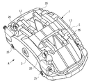
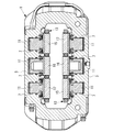
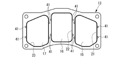
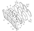
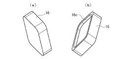
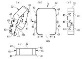
図1は本発明に係るピストン対向型のディスクブレーキ装置の一実施の形態の斜め上方から見た斜視図、図2は図1のA矢視図、図3は図2のB−B断面図,図4は図1に示したインナ側のライニング組立体の裏面側からの斜視図、図5は図4に示したライニング組立体の側面図、図6は図4に示したライニング組立体の正面図、図7は図4に示したライニング組立体の裏面図、図8は図4に示したライニング組立体の分解斜視図である。また、図9(a)は図8に示した第2のライニング本体の正面側からの斜視図、図9(b)は同ライニング本体の裏面側からの斜視図、図10(a)は図8に示した第2のライニング保持スプリングの斜視図、図10(b)は同ライニング保持スプリングの正面図、図10(c)は図10(b)のD矢視図、図10(d)は図10(b)のE矢視図である。また、図11はライニング組立体におけるガイドプレートに対するライニング保持スプリングの位置の説明図で、(a)は初期位置、(b)は制動時の位置、(c)は戻り時の位置の説明図である。
Hereinafter, preferred embodiments of a disc brake device according to the present invention will be described in detail with reference to the drawings.
1 is a perspective view of an embodiment of a piston-facing disc brake device according to the present invention as viewed obliquely from above, FIG. 2 is a view taken along arrow A in FIG. 1, and FIG. 3 is a cross-sectional view taken along line BB in FIG. 4 is a perspective view from the back side of the inner side lining assembly shown in FIG. 1, FIG. 5 is a side view of the lining assembly shown in FIG. 4, and FIG. 6 is a side view of the lining assembly shown in FIG. 7 is a rear view of the lining assembly shown in FIG. 4, and FIG. 8 is an exploded perspective view of the lining assembly shown in FIG. 9A is a perspective view from the front side of the second lining body shown in FIG. 8, FIG. 9B is a perspective view from the back side of the lining body, and FIG. FIG. 10B is a front view of the lining holding spring shown in FIG. 8, FIG. 10C is a front view of the lining holding spring, and FIG. FIG. 11 is a view on arrow E in FIG. FIG. 11 is an explanatory diagram of the position of the lining holding spring with respect to the guide plate in the lining assembly, where (a) is an initial position, (b) is a position during braking, and (c) is an explanatory diagram of a position when returning. is there.
この実施の形態のディスクブレーキ装置1は、所謂ピストン対向型のディスクブレーキ装置で、不図示のディスクロータを跨いで対向するインナキャリパ部3とアウタキャリパ部5の各々が3個のシリンダ7を有し、それぞれのシリンダ7に装着されたピストン11でインナ側及びアウタ側のそれぞれのライニング組立体13をディスクロータ側に移動し、各ライニング組立体13上のライニング15,16,17をディスクロータに押圧して制動力を得る。
各キャリパ3,5に装備される3個のシリンダ7相互は、ディスクロータの周方向に離間して配置されている。
The disc brake device 1 according to this embodiment is a so-called piston-facing disc brake device, and each of the
The three
インナ側及びアウタ側のそれぞれのライニング組立体13は、図4乃至図8に示すように、各キャリパ3,5のピストン配置に対応して3個のライニング保持孔21,22,23が貫通形成されてインナ側及びアウタ側の各キャリパ3,5にボルト25により固定されるガイドプレート27と、各ガイドプレート27の各ライニング保持孔21,22,23に嵌合保持されたライニング保持スプリング31,32,33と、ライニング保持スプリング31,32,33に保持されるライニング15,16,17とを備えている。
As shown in FIGS. 4 to 8, each of the inner side and outer
ライニング保持スプリング31,32,33は、各ガイドプレート27のライニング保持孔21,22,23毎に帯状板材をそれぞれのライニング保持孔の内周に沿う略リング状に湾曲成形して形成されたもので、各ライニング保持孔21,22,23に該孔の貫通方向に摺動可能に嵌合保持されている。
また、各ライニング保持スプリング31,32,33は、図8及び図10(b)に示すように、一部に切り離された離間部31a,32a,33aを有しており、この離間部31a,32a,33aを有していることにより、縮径方向及び拡径方向に弾性変形可能になっている。
The
Further, as shown in FIGS. 8 and 10 (b), the lining holding
各ライニング保持スプリング31,32,33には、ディスクロータ側に面したガイドプレート27の表面27aに当接してライニング15,16,17の後退位置を規制する後退規制爪(規制部材)41と、制動時にディスクロータ側にライニング保持孔21,22,23内を摺動移動した際にガイドプレート27の裏面27bに当接してライニング保持スプリング31,32,33の最大進出位置を規制する進出規制爪(規制部材)43と、制動解除時に後退規制爪41がガイドプレート27の表面27aに当接する位置に戻るようにガイドプレート27の裏面27bを押圧する戻しスプリング爪45と、が一体形成されている。
Each of the lining holding
これらの後退規制爪41、進出規制爪43、戻しスプリング爪45は、帯状板材の両側縁に形成された突片を、折曲げ成形することにより形成されている。
後退規制爪41と進出規制爪43との間の幅寸法W1(図10(c)参照)は、ガイドプレート27の板厚分t(図8参照)に、制動動作時のライニング15,16,17の移動分s(図11参照)を加算した値に設定されている。
即ち、W1=t+sとなっている。
The
The width dimension W1 (see FIG. 10C) between the
That is, W1 = t + s.
本実施の形態のライニング保持スプリング31,32,33は、図10(b)に矢印Xで示すように、離間部31a,32a,33a側を内側に付勢して、縮径した状態で、ガイドプレート27のライニング保持孔21,22,23に挿通させた状態にし、その状態で縮径状態を解除すると、各スプリングにおける後退規制爪41及び戻しスプリング爪45がライニング保持孔の周縁部を挟持した状態になり、各ライニング保持孔21,22,23に脱落不能に保持される。
As shown by the arrow X in FIG. 10B, the lining holding springs 31, 32, and 33 of the present embodiment are biased inwardly on the side of the separating
そして、ライニング保持孔21,22,23にライニング保持スプリング31,32,33を装着した状態で、各ライニング保持スプリング31,32,33の内側にライニング15,16,17を嵌合装着すると、各ライニング保持スプリング31,32,33が嵌合摩擦力により各ライニング15,16,17を保持し、結果的に、各ライニング保持孔21,22,23にライニング15,16,17が保持された状態になる。
また、ライニング保持スプリング31,32,33は各ライニング15,16,17を進退可能にも嵌合しており、各ライニング15,16,17の磨耗が進行すると、ライニング保持スプリング31,32,33に対して摩耗分進出できるように保持している。
When the lining holding springs 31, 32, 33 are mounted in the
Further, the lining holding springs 31, 32, 33 are fitted so that the
ライニング保持スプリング31,32,33を介してライニング15,16,17をガイドプレート27に装着した初期状態では、戻しスプリング爪45による付勢力により、ライニング保持スプリング31,32,33は、後退規制爪41をガイドプレート27の表面27aに当接させて、最大限に後退した位置にあり、図11(a)に示すように、進出規制爪43と裏面27bとの間には、隙間sが確保されている。
In the initial state in which the
ライニング保持スプリング31,32,33に使用する帯状板材は、バネ特性に優れたものが好ましく、例えば、ばね用の鋼板やステンレス鋼板やりん青銅板などが使用される。 The belt-like plate material used for the lining holding springs 31, 32, 33 is preferably one having excellent spring characteristics, and for example, a spring steel plate, a stainless steel plate, a phosphor bronze plate, or the like is used.
また、本実施の形態における各ライニング15,16,17は、図8に示すように、表面がディスクロータに押圧されるライニング本体15a,16a,17aと、これらのライニング本体15a,16a,17aの裏面に嵌合保持されてピストン11からの押圧力を受ける補強板15b,16b,17bとで構成されている。
Further, as shown in FIG. 8, the
ライニング本体15a,16a,17aは、図7及び図9(b)に示すように、その裏面に、補強板15b,16b,17bが嵌合する凹部15c,16c,17cを形成している。
補強板15b,16b,17bは、凹部15c,16c,17cに嵌合することで、ライニング本体15a,16a,17aに一体化される。
As shown in FIGS. 7 and 9 (b), the lining
The reinforcing
以上に説明したディスクブレーキ装置1では、制動時には、キャリパに支持されたピストン11から押圧力を受けた各ライニング15,16,17は、該ライニング15,16,17を保持しているライニング保持スプリング31,32,33と一体に、キャリパに固定されているガイドプレート27のライニング保持孔21,22,23上をディスクロータ側に摺動移動して、ディスクロータに押圧されて、制動力を発生する。
制動時に、ライニング保持スプリング31,32,33が最大限にディスクロータ側に移動した時には、図11(b)に示すように、進出規制爪43がガイドプレート27の裏面27bに当接して、進出規制爪43と裏面27bとの間の隙間sは無くなる。
In the disc brake device 1 described above, at the time of braking, the
When braking, when the lining holding springs 31, 32, 33 are moved to the disk rotor side as much as possible, the
ライニング保持スプリング31,32,33に保持された各ライニング15,16,17は、更に摩耗が進むと、ライニング保持スプリング31,32,33自体の進出規制爪43による進出規制を受けるが、先に説明したように、ライニング保持スプリング31,32,33に進退可能に嵌合されているため、ライニング保持スプリング31,32,33に対し摩耗分進出できる。
As the
そして、上記構成のディスクブレーキ装置1では、ディスクロータに押圧されるライニング15,16,17は、キャリパに装備される複数個のピストン11毎に独立した小型のもので、ピストン11毎にディスクロータに押圧されるため、複数個のピストンで一つの一体化したライニング本体をディスクロータに押圧する従来のディスクブレーキ装置と比較すると、ディスクロータの摺動面の凹凸や熱変形によってライニング本体15a,16a,17aとディスクロータとの接触面積が低減することを抑止することができ、よって、接触面積の低減による制動性能の低下を防止することができる。
In the disc brake device 1 configured as described above, the
また、ガイドプレート27のライニング保持孔21,22,23内にライニング本体15a,16a,17aを保持するライニング保持スプリング31,32,33は、ガイドプレート27の板厚分tに、制動動作時のライニング15,16,17の移動分sを加算した幅寸法W1を備えているため、制動時のライニング本体15a,16a,17aの移動動作で、ライニング本体15a,16a,17aの外周部がガイドプレート27に擦れることを防止でき、よって、ガイドプレート27との擦れによってライニング本体15a,16a,17aの外周面が傷つくことがなく、ライニング本体15a,16a,17aの外周面の傷つきによる破損を防止することができる。
Further, the lining holding springs 31, 32, 33 for holding the
更に、上記ディスクブレーキ装置1では、制動時にライニング本体15a,16a,17aと一体にライニング保持スプリング31,32,33がディスクロータ側に移動したときに、戻しスプリング爪45がガイドプレート27の裏面27bに押圧されて弾性変形し、制動解除時には、この戻しスプリング爪45の復元力で、ライニング保持スプリング31,32,33がライニング本体15a,16a,17aを保持してディスクロータから離間する方向に引き戻され、図11(c)に示すように、進出規制爪43とガイドプレート27の裏面27bとの間に隙間sが確保された状態に戻る。
そのため、非制動時にライニング本体15a,16a,17aがディスクロータに接触してしまう引き摺りの発生を防止することができる。
Further, in the disc brake device 1, when the lining holding springs 31, 32, 33 are moved together with the lining
Therefore, it is possible to prevent the occurrence of dragging in which the
そして、制動解除時にライニング本体15a,16a,17aをディスクロータから引き離す戻しスプリング爪45は、ライニング本体15a,16a,17aをライニング保持孔21,22,23に保持させるために、ライニング保持孔21,22,23に装着されるライニング保持スプリング31,32,33に一体形成されたものであるため、部品の増加を招かない。また、ライニング保持スプリング31,32,33は、帯状板材をライニング保持孔21,22,23の内周に沿う略リング状に湾曲成形したもので、先に説明したように、縮径方向に弾性変形させた状態でライニング保持孔21,22,23に挿通させた後、縮径方向の弾性変形を解除することにより、簡単にガイドプレート27に採り付けることができる。
即ち、スプリング爪45を備えたことで、組立性の低下を招く要因である部品の増加や組立て工程の増加などが発生することがない。従って、組立性の低下を招くことなく引き摺りの発生を防止することができる。
The
That is, the provision of the
また、上記ディスクブレーキ装置1では、ライニング本体15a,16a,17aの裏面に装着されてピストン11からの押圧力を受ける補強板15b,16b,17bは、ライニング本体15a,16a,17aの裏面の凹部15c,16c,17cに嵌合保持されて、使用済みのライニング15,16,17においてライニング本体15a,16a,17aと補強板15b,16b,17bとに分離することが比較的に容易にでき、ライニング15,16,17のリサイクル化も容易になる。
Further, in the disc brake device 1, the reinforcing
なお、上記実施の形態に示したディスクブレーキ装置1は、インナキャリパ部3及びアウタキャリパ部5のそれぞれに、3個のシリンダ7を備えた構成のピストン対向型のディスクブレーキ装置であった。しかし、各キャリパに装備されるシリンダの数量は、上記実施の形態に限定しない。
即ち、本発明に係るピストン対向型のディスクブレーキ装置において、各キャリパに装備されるシリンダの数量は、任意の数量に設定することが可能で、シリンダ数に相応して、シリンダ毎に独立してライニングを装備するようにすれば良い。
The disc brake device 1 shown in the above embodiment is a piston-facing disc brake device having three
That is, in the piston-facing disc brake device according to the present invention, the number of cylinders provided in each caliper can be set to an arbitrary number, and each cylinder can be independently set according to the number of cylinders. Equipped with a lining.
1 ディスクブレーキ装置
3 インナキャリパ部
5 アウタキャリパ部
7 シリンダ
11 ピストン
13 ライニング組立体
15,16,17 ライニング
15a,16a,17a ライニング本体
15b,16b,17b 補強板
15c,16c,17c 凹部
21,22,23 ライニング保持孔
31,32,33 ライニング保持スプリング
31a,32a,33a 離間部
41 後退規制爪(規制部材)
43 進出規制爪(規制部材)
45 戻しスプリング爪
DESCRIPTION OF SYMBOLS 1
43 Advance restriction claw (regulation member)
45 Return spring claw
Claims (4)
複数個のライニング保持孔が貫通形成されて各キャリパに固定されるガイドプレートと、
各ガイドプレートの各ライニング保持孔の内周に沿う略リング状に湾曲成形されると共に、各ライニング保持孔の貫通方向に摺動可能に嵌合保持される複数個のライニング保持スプリングと、
前記ライニング保持スプリングに保持される複数個のライニングとを備え、
前記ライニング保持スプリングは、前記ガイドプレートの板厚分に、制動動作時の前記ライニングの移動分を加算した幅寸法を備えていることを特徴とするディスクブレーキ装置。 Each of the inner caliper portion and the outer caliper portion has two or more cylinders, and is a piston-facing disc brake that obtains a braking force by pressing the lining against the disc rotor with pistons mounted on the respective cylinders,
A plurality of lining retaining holes formed through the guide plate fixed to each caliper;
A plurality of lining holding springs that are curved and formed in a substantially ring shape along the inner periphery of each lining holding hole of each guide plate, and are fitted and held slidably in the penetrating direction of each lining holding hole;
A plurality of linings held by the lining holding spring;
The disc brake device according to claim 1, wherein the lining holding spring has a width dimension obtained by adding a moving amount of the lining during a braking operation to a thickness of the guide plate.
Priority Applications (1)
| Application Number | Priority Date | Filing Date | Title |
|---|---|---|---|
| JP2008163575A JP4854709B2 (en) | 2008-06-23 | 2008-06-23 | Disc brake device |
Applications Claiming Priority (1)
| Application Number | Priority Date | Filing Date | Title |
|---|---|---|---|
| JP2008163575A JP4854709B2 (en) | 2008-06-23 | 2008-06-23 | Disc brake device |
Publications (2)
| Publication Number | Publication Date |
|---|---|
| JP2010002041A true JP2010002041A (en) | 2010-01-07 |
| JP4854709B2 JP4854709B2 (en) | 2012-01-18 |
Family
ID=41583915
Family Applications (1)
| Application Number | Title | Priority Date | Filing Date |
|---|---|---|---|
| JP2008163575A Active JP4854709B2 (en) | 2008-06-23 | 2008-06-23 | Disc brake device |
Country Status (1)
| Country | Link |
|---|---|
| JP (1) | JP4854709B2 (en) |
Citations (5)
| Publication number | Priority date | Publication date | Assignee | Title |
|---|---|---|---|---|
| JPS5012625Y1 (en) * | 1968-05-30 | 1975-04-18 | ||
| JPS56148127A (en) * | 1980-04-18 | 1981-11-17 | Meidensha Electric Mfg Co Ltd | Method of countermeasuring malfunction of breaker of power distribution line |
| JPH03130927A (en) * | 1989-10-14 | 1991-06-04 | Nikon Corp | Signal processing circuit for optical recording and reproducing device |
| JP2006207655A (en) * | 2005-01-26 | 2006-08-10 | Hitachi Ltd | Disk brake and brake pad |
| JP2008106850A (en) * | 2006-10-25 | 2008-05-08 | Akebono Brake Ind Co Ltd | Friction pad assembly for disc brake, and disc brake device for vehicle |
-
2008
- 2008-06-23 JP JP2008163575A patent/JP4854709B2/en active Active
Patent Citations (5)
| Publication number | Priority date | Publication date | Assignee | Title |
|---|---|---|---|---|
| JPS5012625Y1 (en) * | 1968-05-30 | 1975-04-18 | ||
| JPS56148127A (en) * | 1980-04-18 | 1981-11-17 | Meidensha Electric Mfg Co Ltd | Method of countermeasuring malfunction of breaker of power distribution line |
| JPH03130927A (en) * | 1989-10-14 | 1991-06-04 | Nikon Corp | Signal processing circuit for optical recording and reproducing device |
| JP2006207655A (en) * | 2005-01-26 | 2006-08-10 | Hitachi Ltd | Disk brake and brake pad |
| JP2008106850A (en) * | 2006-10-25 | 2008-05-08 | Akebono Brake Ind Co Ltd | Friction pad assembly for disc brake, and disc brake device for vehicle |
Also Published As
| Publication number | Publication date |
|---|---|
| JP4854709B2 (en) | 2012-01-18 |
Similar Documents
| Publication | Publication Date | Title |
|---|---|---|
| JP4715124B2 (en) | Laminated shim for disc brake and pad unit having the laminated shim | |
| US20150247542A1 (en) | Disc brake | |
| US9175738B2 (en) | Disc brake | |
| JP4765888B2 (en) | Disc brake pad set | |
| US9862362B2 (en) | Vehicle disc brake | |
| KR101570632B1 (en) | Brake lining for railway vehicle, and disc brake with same | |
| JP4854709B2 (en) | Disc brake device | |
| JP2010203559A (en) | Floating caliper type disk brake | |
| JP2007218395A (en) | Brake calliper | |
| KR20140036632A (en) | Caliper brake for a vehicle | |
| KR101405205B1 (en) | Disc brake for vehicle | |
| JP5112384B2 (en) | Vehicle disc brake | |
| JP2012072848A (en) | Disc brake and friction pad | |
| JP5988028B2 (en) | Disc brake and pad support | |
| JP2017150589A (en) | Disc brake | |
| JP2009174610A (en) | Disc brake | |
| JP7213994B2 (en) | disc brake | |
| JP4730692B2 (en) | Pad spring for disc brake device | |
| JP5087491B2 (en) | Disc brake | |
| JP3976047B2 (en) | Disc brake device | |
| JPH07280004A (en) | Disk brake | |
| JP2012167739A (en) | Disk brake | |
| US20230010464A1 (en) | Pad clip for disc brake apparatus and disc brake apparatus | |
| JP2006170251A (en) | Disk brake | |
| JP2012072852A (en) | Brake pad |
Legal Events
| Date | Code | Title | Description |
|---|---|---|---|
| A621 | Written request for application examination |
Free format text: JAPANESE INTERMEDIATE CODE: A621 Effective date: 20110307 |
|
| TRDD | Decision of grant or rejection written | ||
| A977 | Report on retrieval |
Free format text: JAPANESE INTERMEDIATE CODE: A971007 Effective date: 20111013 |
|
| A01 | Written decision to grant a patent or to grant a registration (utility model) |
Free format text: JAPANESE INTERMEDIATE CODE: A01 Effective date: 20111018 |
|
| A01 | Written decision to grant a patent or to grant a registration (utility model) |
Free format text: JAPANESE INTERMEDIATE CODE: A01 |
|
| A61 | First payment of annual fees (during grant procedure) |
Free format text: JAPANESE INTERMEDIATE CODE: A61 Effective date: 20111025 |
|
| FPAY | Renewal fee payment (event date is renewal date of database) |
Free format text: PAYMENT UNTIL: 20141104 Year of fee payment: 3 |
|
| R150 | Certificate of patent or registration of utility model |
Ref document number: 4854709 Country of ref document: JP Free format text: JAPANESE INTERMEDIATE CODE: R150 Free format text: JAPANESE INTERMEDIATE CODE: R150 |
|
| R250 | Receipt of annual fees |
Free format text: JAPANESE INTERMEDIATE CODE: R250 |
|
| R250 | Receipt of annual fees |
Free format text: JAPANESE INTERMEDIATE CODE: R250 |
|
| R250 | Receipt of annual fees |
Free format text: JAPANESE INTERMEDIATE CODE: R250 |
|
| R250 | Receipt of annual fees |
Free format text: JAPANESE INTERMEDIATE CODE: R250 |