JP2010002014A - Vehicle power transmitting device - Google Patents
Vehicle power transmitting device Download PDFInfo
- Publication number
- JP2010002014A JP2010002014A JP2008162585A JP2008162585A JP2010002014A JP 2010002014 A JP2010002014 A JP 2010002014A JP 2008162585 A JP2008162585 A JP 2008162585A JP 2008162585 A JP2008162585 A JP 2008162585A JP 2010002014 A JP2010002014 A JP 2010002014A
- Authority
- JP
- Japan
- Prior art keywords
- gear
- planetary gear
- electric motor
- power transmission
- oil pump
- Prior art date
- Legal status (The legal status is an assumption and is not a legal conclusion. Google has not performed a legal analysis and makes no representation as to the accuracy of the status listed.)
- Granted
Links
Images

Classifications
-
- F—MECHANICAL ENGINEERING; LIGHTING; HEATING; WEAPONS; BLASTING
- F16—ENGINEERING ELEMENTS AND UNITS; GENERAL MEASURES FOR PRODUCING AND MAINTAINING EFFECTIVE FUNCTIONING OF MACHINES OR INSTALLATIONS; THERMAL INSULATION IN GENERAL
- F16H—GEARING
- F16H57/00—General details of gearing
- F16H57/04—Features relating to lubrication or cooling or heating
- F16H57/0434—Features relating to lubrication or cooling or heating relating to lubrication supply, e.g. pumps ; Pressure control
- F16H57/0441—Arrangements of pumps
-
- B—PERFORMING OPERATIONS; TRANSPORTING
- B60—VEHICLES IN GENERAL
- B60K—ARRANGEMENT OR MOUNTING OF PROPULSION UNITS OR OF TRANSMISSIONS IN VEHICLES; ARRANGEMENT OR MOUNTING OF PLURAL DIVERSE PRIME-MOVERS IN VEHICLES; AUXILIARY DRIVES FOR VEHICLES; INSTRUMENTATION OR DASHBOARDS FOR VEHICLES; ARRANGEMENTS IN CONNECTION WITH COOLING, AIR INTAKE, GAS EXHAUST OR FUEL SUPPLY OF PROPULSION UNITS IN VEHICLES
- B60K1/00—Arrangement or mounting of electrical propulsion units
-
- B—PERFORMING OPERATIONS; TRANSPORTING
- B60—VEHICLES IN GENERAL
- B60L—PROPULSION OF ELECTRICALLY-PROPELLED VEHICLES; SUPPLYING ELECTRIC POWER FOR AUXILIARY EQUIPMENT OF ELECTRICALLY-PROPELLED VEHICLES; ELECTRODYNAMIC BRAKE SYSTEMS FOR VEHICLES IN GENERAL; MAGNETIC SUSPENSION OR LEVITATION FOR VEHICLES; MONITORING OPERATING VARIABLES OF ELECTRICALLY-PROPELLED VEHICLES; ELECTRIC SAFETY DEVICES FOR ELECTRICALLY-PROPELLED VEHICLES
- B60L1/00—Supplying electric power to auxiliary equipment of vehicles
- B60L1/003—Supplying electric power to auxiliary equipment of vehicles to auxiliary motors, e.g. for pumps, compressors
-
- B—PERFORMING OPERATIONS; TRANSPORTING
- B60—VEHICLES IN GENERAL
- B60L—PROPULSION OF ELECTRICALLY-PROPELLED VEHICLES; SUPPLYING ELECTRIC POWER FOR AUXILIARY EQUIPMENT OF ELECTRICALLY-PROPELLED VEHICLES; ELECTRODYNAMIC BRAKE SYSTEMS FOR VEHICLES IN GENERAL; MAGNETIC SUSPENSION OR LEVITATION FOR VEHICLES; MONITORING OPERATING VARIABLES OF ELECTRICALLY-PROPELLED VEHICLES; ELECTRIC SAFETY DEVICES FOR ELECTRICALLY-PROPELLED VEHICLES
- B60L15/00—Methods, circuits, or devices for controlling the traction-motor speed of electrically-propelled vehicles
- B60L15/20—Methods, circuits, or devices for controlling the traction-motor speed of electrically-propelled vehicles for control of the vehicle or its driving motor to achieve a desired performance, e.g. speed, torque, programmed variation of speed
- B60L15/2054—Methods, circuits, or devices for controlling the traction-motor speed of electrically-propelled vehicles for control of the vehicle or its driving motor to achieve a desired performance, e.g. speed, torque, programmed variation of speed by controlling transmissions or clutches
-
- B—PERFORMING OPERATIONS; TRANSPORTING
- B60—VEHICLES IN GENERAL
- B60L—PROPULSION OF ELECTRICALLY-PROPELLED VEHICLES; SUPPLYING ELECTRIC POWER FOR AUXILIARY EQUIPMENT OF ELECTRICALLY-PROPELLED VEHICLES; ELECTRODYNAMIC BRAKE SYSTEMS FOR VEHICLES IN GENERAL; MAGNETIC SUSPENSION OR LEVITATION FOR VEHICLES; MONITORING OPERATING VARIABLES OF ELECTRICALLY-PROPELLED VEHICLES; ELECTRIC SAFETY DEVICES FOR ELECTRICALLY-PROPELLED VEHICLES
- B60L2240/00—Control parameters of input or output; Target parameters
- B60L2240/40—Drive Train control parameters
- B60L2240/42—Drive Train control parameters related to electric machines
- B60L2240/421—Speed
-
- F—MECHANICAL ENGINEERING; LIGHTING; HEATING; WEAPONS; BLASTING
- F16—ENGINEERING ELEMENTS AND UNITS; GENERAL MEASURES FOR PRODUCING AND MAINTAINING EFFECTIVE FUNCTIONING OF MACHINES OR INSTALLATIONS; THERMAL INSULATION IN GENERAL
- F16H—GEARING
- F16H57/00—General details of gearing
- F16H57/04—Features relating to lubrication or cooling or heating
- F16H57/0467—Elements of gearings to be lubricated, cooled or heated
- F16H57/0476—Electric machines and gearing, i.e. joint lubrication or cooling or heating thereof
-
- F—MECHANICAL ENGINEERING; LIGHTING; HEATING; WEAPONS; BLASTING
- F16—ENGINEERING ELEMENTS AND UNITS; GENERAL MEASURES FOR PRODUCING AND MAINTAINING EFFECTIVE FUNCTIONING OF MACHINES OR INSTALLATIONS; THERMAL INSULATION IN GENERAL
- F16H—GEARING
- F16H57/00—General details of gearing
- F16H57/04—Features relating to lubrication or cooling or heating
- F16H57/048—Type of gearings to be lubricated, cooled or heated
- F16H57/0482—Gearings with gears having orbital motion
- F16H57/0483—Axle or inter-axle differentials
-
- F—MECHANICAL ENGINEERING; LIGHTING; HEATING; WEAPONS; BLASTING
- F16—ENGINEERING ELEMENTS AND UNITS; GENERAL MEASURES FOR PRODUCING AND MAINTAINING EFFECTIVE FUNCTIONING OF MACHINES OR INSTALLATIONS; THERMAL INSULATION IN GENERAL
- F16H—GEARING
- F16H57/00—General details of gearing
- F16H57/04—Features relating to lubrication or cooling or heating
- F16H57/048—Type of gearings to be lubricated, cooled or heated
- F16H57/0482—Gearings with gears having orbital motion
- F16H57/0486—Gearings with gears having orbital motion with fixed gear ratio
-
- Y—GENERAL TAGGING OF NEW TECHNOLOGICAL DEVELOPMENTS; GENERAL TAGGING OF CROSS-SECTIONAL TECHNOLOGIES SPANNING OVER SEVERAL SECTIONS OF THE IPC; TECHNICAL SUBJECTS COVERED BY FORMER USPC CROSS-REFERENCE ART COLLECTIONS [XRACs] AND DIGESTS
- Y02—TECHNOLOGIES OR APPLICATIONS FOR MITIGATION OR ADAPTATION AGAINST CLIMATE CHANGE
- Y02T—CLIMATE CHANGE MITIGATION TECHNOLOGIES RELATED TO TRANSPORTATION
- Y02T10/00—Road transport of goods or passengers
- Y02T10/60—Other road transportation technologies with climate change mitigation effect
- Y02T10/64—Electric machine technologies in electromobility
-
- Y—GENERAL TAGGING OF NEW TECHNOLOGICAL DEVELOPMENTS; GENERAL TAGGING OF CROSS-SECTIONAL TECHNOLOGIES SPANNING OVER SEVERAL SECTIONS OF THE IPC; TECHNICAL SUBJECTS COVERED BY FORMER USPC CROSS-REFERENCE ART COLLECTIONS [XRACs] AND DIGESTS
- Y02—TECHNOLOGIES OR APPLICATIONS FOR MITIGATION OR ADAPTATION AGAINST CLIMATE CHANGE
- Y02T—CLIMATE CHANGE MITIGATION TECHNOLOGIES RELATED TO TRANSPORTATION
- Y02T10/00—Road transport of goods or passengers
- Y02T10/60—Other road transportation technologies with climate change mitigation effect
- Y02T10/72—Electric energy management in electromobility
Landscapes
- Engineering & Computer Science (AREA)
- Mechanical Engineering (AREA)
- Power Engineering (AREA)
- Transportation (AREA)
- General Engineering & Computer Science (AREA)
- Chemical & Material Sciences (AREA)
- Combustion & Propulsion (AREA)
- General Details Of Gearings (AREA)
- Hybrid Electric Vehicles (AREA)
- Arrangement Or Mounting Of Propulsion Units For Vehicles (AREA)
Abstract
Description
本発明は、車両の動力伝達装置に係り、遊星歯車装置を介して動力を伝達する技術に関するものである。 The present invention relates to a power transmission device for a vehicle, and relates to a technique for transmitting power via a planetary gear device.
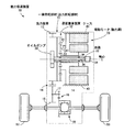
動力源からの動力を遊星歯車装置を介して出力側へ伝達する車両の動力伝達装置がよく知られている。例えば、特許文献1には、図6に示すように、遊星歯車部1において、サンギヤSに電動モータ2を連結し、リングギヤRをケース3に固定し、キャリヤCAを出力ギヤ部4に連結するとともにオイルポンプ5に連結することで、遊星歯車部1を減速機として機能させてオイルポンプ5を電動モータ2よりも低回転速度で駆動し、電動モータによって駆動されるオイルポンプの劣化を低減して耐久性を向上させる電気自動車のパワートレーンが記載されている。
A vehicle power transmission device that transmits power from a power source to an output side via a planetary gear device is well known. For example, in
しかしながら、特許文献1のようなキャリヤ出力の構成では、破線部Aに示すように、遊星歯車部1と出力ギヤ部4とを遊星歯車部1の軸心方向にオフセットしなければ連結できない為、軸心方向に相応のスペースが必要となり、パワートレーン自体が軸心方向に大型化する恐れがあった。
However, in the configuration of the carrier output as in
また、一般的には、遊星歯車部1の潤滑の為にはオイルポンプ5をその遊星歯車部1と同じ軸心上に配置することが有利であることから、図6に示すように遊星歯車部1とオイルポンプ5とを同軸心上に配置する構成が採用される。しかしながら、このような構成では、図6から明らかなようにパワートレーン自体が軸心方向に一層大型化する恐れがあった。尚、上述したような課題は未公知である。
In general, it is advantageous to arrange the oil pump 5 on the same axis as that of the
本発明は、以上の事情を背景として為されたものであり、その目的とするところは、軸心方向の省スペース化を図り、軸心方向に小型化することができる車両の動力伝達装置を提供することにある。 The present invention has been made against the background of the above circumstances, and an object of the present invention is to provide a vehicle power transmission device that can save space in the axial direction and can be reduced in size in the axial direction. It is to provide.
前記目的を達成するための本発明の要旨とするところは、(a) 動力源からの動力を遊星歯車装置を介して出力側へ伝達する車両の動力伝達装置であって、(b) 前記遊星歯車装置は、サンギヤが前記動力源に連結され、キャリヤが回転不能に固定され、リングギヤが出力回転部材に連結されて、前記動力源の回転速度を減速して前記出力回転部材に伝達する減速機であり、(c) 前記リングギヤには更にオイルポンプが連結されることにある。 To achieve the above object, the gist of the present invention is: (a) a vehicle power transmission device that transmits power from a power source to an output side via a planetary gear device, and (b) the planetary gear. The gear device includes a sun gear connected to the power source, a carrier fixed in a non-rotatable manner, and a ring gear connected to the output rotating member, and a reduction gear that reduces the rotational speed of the power source and transmits the reduced speed to the output rotating member. (C) An oil pump is further connected to the ring gear.
このようにすれば、遊星歯車装置においてキャリヤ固定・リングギヤ出力とする構成とされる。従って、例えばリングギヤと出力回転部材の一部とを一体化する構造を採用することができ、リングギヤ固定・キャリヤ出力のように出力回転部材を軸心方向でオフセットしてキャリヤに連結する必要がある構成に比較して、軸心方向のスペースを省略でき、動力伝達装置を小型化することができる。すなわち、軸心方向の省スペース化が図られ、軸心方向に小型化される車両の動力伝達装置が提供される。
また、出力側に連結されたオイルポンプの回転速度が入力側の動力源の回転速度から減速されるので、オイルポンプの使用回転速度を抑制することができる。よって、オイルポンプの耐久性を向上することができる。
If it does in this way, it will be set as the structure made into a carrier fixed and ring gear output in a planetary gear apparatus. Therefore, for example, it is possible to adopt a structure in which the ring gear and a part of the output rotating member are integrated, and it is necessary to offset the output rotating member in the axial direction and connect it to the carrier as in ring gear fixing / carrier output. Compared to the configuration, the space in the axial direction can be omitted, and the power transmission device can be reduced in size. That is, a power transmission device for a vehicle that is space-saving in the axial direction and is downsized in the axial direction is provided.
Moreover, since the rotational speed of the oil pump connected to the output side is decelerated from the rotational speed of the power source on the input side, the use rotational speed of the oil pump can be suppressed. Therefore, the durability of the oil pump can be improved.
ここで、好適には、前記オイルポンプは、前記遊星歯車装置と同じ軸心上に配置されており、前記オイルポンプの構成部材の少なくとも一部は、前記リングギヤと一体回転する一体回転部材の内周側に配置される。このようにすれば、オイルポンプを遊星歯車装置と同軸心上に配置する場合に、リングギヤの内周側にオイルポンプが備えられ、動力伝達装置自体の全長が短縮される。すなわち、オイルポンプがリングギヤに対して入れ子構造とされるので、軸心方向の省スペース化が一層図られる。 Here, preferably, the oil pump is disposed on the same axis as the planetary gear device, and at least a part of the constituent members of the oil pump is an inner rotating member that rotates integrally with the ring gear. It is arranged on the circumferential side. In this way, when the oil pump is arranged coaxially with the planetary gear device, the oil pump is provided on the inner peripheral side of the ring gear, and the overall length of the power transmission device itself is shortened. That is, since the oil pump is nested in the ring gear, space saving in the axial direction can be further achieved.
また、好適には、前記一体回転部材は、カウンタ軸のドリブンギヤと噛み合うことによって動力を駆動輪へ出力する為の外周歯を備えた円筒状部材であって、前記出力回転部材として機能する。このようにすれば、動力伝達装置の軸心方向の寸法が確実に短縮される。 Preferably, the integral rotating member is a cylindrical member having outer peripheral teeth for outputting power to the driving wheel by meshing with the driven gear of the counter shaft, and functions as the output rotating member. In this way, the axial dimension of the power transmission device is reliably shortened.
また、好適には、前記遊星歯車装置を潤滑するための潤滑油をその遊星歯車装置の回転中心部から放出するための油路が前記オイルポンプから前記軸心に沿って設けられている。このようにすれば、遊星歯車装置の軸心側からオイルを遠心力で飛ばして遊星歯車装置を潤滑(冷却)することができるので、遊星歯車装置の焼付き防止に有利となる。また、油路長が短くなる利点がある。 Preferably, an oil passage for releasing lubricating oil for lubricating the planetary gear device from the rotation center of the planetary gear device is provided from the oil pump along the axis. By doing so, it is possible to lubricate (cool) the planetary gear device by blowing oil from the axial center side of the planetary gear device by centrifugal force, which is advantageous in preventing seizure of the planetary gear device. In addition, there is an advantage that the oil passage length is shortened.
また、好適には、前記動力源は、前記オイルポンプと共に前記遊星歯車装置と同じ軸心上に配置された電動モータであり、前記油路は、前記電動モータを冷却するための潤滑油をその電動モータの回転中心部から放出する。このようにすれば、電動モータの軸心側から冷却用にオイルを回すことができるので、電動モータの冷却上有利となる。また、油路長が短くなる利点がある。
また、前記遊星歯車装置によりオイルポンプの回転速度が電動モータの回転速度から減速されることから、電動モータの最高回転速度を引き上げられ、電動モータの小型化に寄与することができる。
Preferably, the power source is an electric motor disposed on the same axis as the planetary gear device together with the oil pump, and the oil passage is provided with lubricating oil for cooling the electric motor. Released from the center of rotation of the electric motor. In this way, oil can be rotated for cooling from the axial center side of the electric motor, which is advantageous for cooling the electric motor. In addition, there is an advantage that the oil passage length is shortened.
Moreover, since the rotational speed of the oil pump is decelerated from the rotational speed of the electric motor by the planetary gear device, the maximum rotational speed of the electric motor can be increased, which contributes to the miniaturization of the electric motor.
また、好適には、本発明の車両の動力伝達装置は、前記動力源が電動モータで構成された電気自動車用の動力伝達装置である。このようにすれば、電動モータを動力源とする電気自動車が適切に構成される。 Preferably, the power transmission device for a vehicle of the present invention is a power transmission device for an electric vehicle in which the power source is an electric motor. If it does in this way, the electric vehicle which uses an electric motor as a power source will be comprised appropriately.
また、好適には、前記動力伝達装置の利用形態としては、例えばこの動力伝達装置を単独の駆動装置として用いた前輪乃至後輪駆動車(2WD)、フロント側の駆動装置とは別にこの動力伝達装置をリヤ側の駆動装置として用いた四輪駆動車(4WD)などが想定される。 Preferably, as a form of use of the power transmission device, for example, the power transmission device is separated from a front wheel or rear wheel drive vehicle (2WD) using the power transmission device as a single drive device, and a front side drive device. A four-wheel drive vehicle (4WD) using the device as a rear drive device is assumed.
以下、本発明の実施例を図面を参照しつつ詳細に説明する。 Hereinafter, embodiments of the present invention will be described in detail with reference to the drawings.
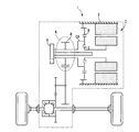
図1は、本発明が適用された動力伝達装置10を説明する概略構成図である。図1において、車体に取り付けられる非回転部材としてのトランスアクスル(T/A)ケース40(以下、ケース40という)内には、動力伝達装置10、走行用の動力源としての駆動用モータである電動モータ20、オイルポンプ30等が備えられている。
FIG. 1 is a schematic configuration diagram illustrating a
動力伝達装置10は、遊星歯車装置12、カウンタギヤ対14、ファイナルギヤ対16、差動歯車装置(終減速機)18を主体として構成されている。そして、動力伝達装置10は、電動モータ20の動力を遊星歯車装置12、カウンタギヤ対14、ファイナルギヤ対16、差動歯車装置(終減速機)18等を順次介して駆動輪50側へ伝達する電気自動車用の動力伝達装置である。
The
遊星歯車装置12は、サンギヤS1と、そのサンギヤS1に対して同心円上に配置されたリングギヤR1と、これらサンギヤS1及びリングギヤR1に噛み合うピニオンギヤP1を自転かつ公転自在に支持するキャリヤCA1とを三つの回転要素として備えて公知の差動作用を生じるシングルピニオン型の遊星歯車機構である。
The
遊星歯車装置12のサンギヤS1には電動モータ20が連結され、キャリヤCA1は回転不能にケース40に固定され、リングギヤR1にはカウンタギヤ対14の一方を構成する出力歯車13が連結されると共にオイルポンプ30が連結される。尚、リングギヤR1と出力歯車13とは、リングギヤR1の外周部に出力歯車13が一体的に設けられた一体回転部材11で構成されている。つまり、この一体回転部材11は、カウンタ軸17のドリブンギヤ15と噛み合うことによって動力を駆動輪へ出力する為の外周歯(すなわち出力歯車13)を備えた円筒状部材であって、出力回転部材として機能するものである。
The sun gear S1 of the
電動モータ20は、例えば同期電動機であって、少なくとも駆動トルクを発生させる電動機としての機能を有しており、遊星歯車装置12と同じ軸心C上に配置されている。この電動モータ20は、例えば不図示のインバータを介してバッテリー、コンデンサなどの蓄電装置に接続され、不図示のマイクロコンピュータを主体とするモータ制御用の電子制御装置によってそのインバータが制御されることにより、出力トルクが調節或いは設定される。尚、発電機としての機能を生じるように構成することも可能であり、この場合には上記マイクロコンピュータによって回生トルクが調節或いは設定される。
The
オイルポンプ30は遊星歯車装置12と同じ軸心C上に配置されており、オイルポンプ30の構成部材の少なくとも一部が軸心C方向において同じ位置となるように上記一体回転部材11(すなわちリングギヤR1、出力歯車13)の内周側に位置し、軸心Cに直角方向においてその一体回転部材11と重なって配置されている。すなわち、オイルポンプ30は遊星歯車装置12と同軸心C上に配置されつつ、オイルポンプ30がリングギヤR1に対して入れ子構造とされる。そして、オイルポンプ30は、電動モータ20により遊星歯車装置12を介してリングギヤR1と共に回転駆動させられて、遊星歯車装置12の回転中心部(軸心C側)から遠心力で飛ばしてその遊星歯車装置12を潤滑したり、電動モータ20の回転中心部(軸心C側)から回してその電動モータ20を冷却したり、不図示のボールベアリングを潤滑したりする為などの潤滑油(オイル)を不図示のオイル溜まりから汲み上げ、油路32を介して供給(放出)する。尚、上記オイル溜まりの潤滑油がファイナルギヤ対16により掻き揚げられる場合に攪拌による損失を低減して効率を上げる為、オイルポンプ30により不図示のキャッチタンクへ潤滑油を上げてオイル溜まりのオイルレベルを下げても良い。
The
油路32は、例えばオイルポンプ30に連結されたシャフト34内においてオイルポンプ30から軸心Cに沿って形成された中空形状孔36と、この中空形状孔36と接続されつつ外周側に向かって形成された放出孔38とから構成されている。
The
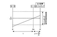
図2は、シングルピニオン型の遊星歯車装置12の各回転要素の回転速度の相対的関係を示す共線図である。この共線図において、縦軸S、縦軸CA、及び縦軸Rは、電動モータ20に連結されたサンギヤS1の回転速度、ケース40に連結されたキャリヤCA1の回転速度、及び出力歯車13とオイルポンプ30とに連結されたリングギヤR1の回転速度をそれぞれ表す軸である。また、それら縦軸S、縦軸CA、及び縦軸Rの相互の間隔は、縦軸Sと縦軸CAとの間隔を1としたとき、縦軸CAと縦軸Rとの間隔がρ(=サンギヤS1の歯数Zs/リングギヤR1の歯数Zr)となるように設定される。このρは1未満であるので、遊星歯車装置12は電動モータ20の回転速度を減速してリングギヤR1(出力歯車13)へ伝達するシングルピニオン型の遊星歯車減速機として機能することがわかる。従って、オイルポンプ30を電動モータ20から減速できるので、オイルポンプ30の使用回転速度を抑制することができる。
FIG. 2 is a collinear diagram showing the relative relationship between the rotational speeds of the rotating elements of the single pinion type
オイルポンプ30を図2の破線に示す使用可能回転速度の範囲内で回転駆動させるには、電動モータ20の最高回転速度を上記ρに合わせて抑制するか、電動モータ20の最高回転速度に合わせて上記ρを設定することが考えられる。例えば、電動モータ20の小型化すなわち電動モータ20の最高回転速度を高速化することが望まれる場合には、上記ρをより小さくしてオイルポンプ30の回転速度を押さえれば良い。但し、サンギヤS1の径を小さくし過ぎず且つリングギヤR1の径を大きくし過ぎない範囲でρを設定する必要がある。
In order to rotate the
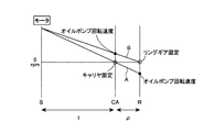
図3は、シングルピニオン型の遊星歯車装置においてキャリヤ固定とリングギヤ固定とで設定するρの違いを説明する図である。図3において、実線Aはキャリヤを回転不能に固定したキャリヤ固定の場合であり本実施例の遊星歯車装置12が相当する。また、実線Bはリングギヤを回転不能に固定したリングギヤ固定の場合であり図6の従来例の遊星歯車部1が相当する。
FIG. 3 is a diagram for explaining a difference in ρ set between carrier fixing and ring gear fixing in a single pinion type planetary gear device. In FIG. 3, a solid line A is a case where the carrier is fixed in a non-rotatable manner and corresponds to the
以下に、使用可能回転速度の範囲が6000rpm程度内のオイルポンプ30を使用し、最高回転速度(許容回転速度)が20000rpm程度の電動モータ20を使用する場合において設定されるρをキャリヤ固定とリングギヤ固定とでそれぞれ算出する。
In the following, when the
キャリヤ固定の場合には、(オイルポンプの回転速度=ρ×モータの回転速度)の関係であるので、ρは0.3程度となる。
一方、リングギヤ固定の場合には、(オイルポンプの回転速度=ρ/(1+ρ)×モータの回転速度)の関係であるので、ρは0.43程度となる。
When the carrier is fixed, the relationship is (rotation speed of the oil pump = ρ × rotation speed of the motor), so ρ is about 0.3.
On the other hand, when the ring gear is fixed, the relationship is (rotational speed of the oil pump = ρ / (1 + ρ) × rotational speed of the motor), so ρ is about 0.43.
このように、リングギヤ固定の方がρを比較的大きくしてもオイルポンプ30の回転速度を押さえることができるので(換言すればρを比較的大きく取れるので)設計的に有利である。しかし、キャリヤ固定でもρが0.3程度あるので、サンギヤS1の径やリングギヤR1の径を考慮しても十分に取り得る値である。従って、電動モータ20の小型化やオイルポンプ30の回転速度を抑制する為に、リングギヤ固定を採用する必要性は極めて低いと考えられる。
As described above, the ring gear fixing is advantageous in design because the rotational speed of the
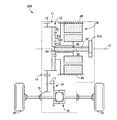
図4は、ハイブリッド車両用の駆動装置100を説明する骨子図である。図4において、駆動装置100は、車体に取り付けられる非回転部材としてのケース110内において、走行用の駆動力源として例えばガソリンエンジンやディーゼルエンジン等の内燃機関であるエンジン200側から順番に、そのエンジン200の出力軸(例えばクランク軸)に作動的に連結されてエンジン200からのトルク変動等による脈動を吸収するダンパー210、そのダンパー210を介してエンジン200によって回転駆動させられる入力軸120、第1電動機130、動力分配機構として機能する第1遊星歯車装置140、減速機として機能する第2遊星歯車装置150、及び第2電動機160を備えている。
FIG. 4 is a skeleton diagram illustrating a
この駆動装置100は、例えば車両において横置きされるFF(フロントエンジン・フロントドライブ)型車両に好適に用いられるものであり、エンジン200の動力がカウンタギヤ対170の一方を構成する駆動装置100の出力回転部材としての出力歯車172からカウンタギヤ対170、ファイナルギヤ対180、差動歯車装置(終減速機)190等を順次介して一対の駆動輪300側へ伝達される。
The
入力軸120は、一端がダンパー210を介してエンジン200に連結されることでエンジン200により回転駆動させられる。また、他端には潤滑油供給装置としてのオイルポンプ220が連結されており入力軸120が回転駆動されることによりオイルポンプ220が回転駆動させられて、駆動装置100の各部例えば第1遊星歯車装置140、第2遊星歯車装置150、不図示のボールベアリング等に潤滑油が供給される。
The
第1遊星歯車装置140は、シングルピニオン型の遊星歯車装置であり、第1サンギヤS11、第1ピニオンギヤP11、その第1ピニオンギヤP11を自転及び公転可能に支持する第1キャリヤCA11、第1ピニオンギヤP11を介して第1サンギヤS11と噛み合う第1リングギヤR11を回転要素(要素)として備えている。
The first
そして、第1遊星歯車装置140は、入力軸120に伝達されたエンジン200の出力を機械的に分配する機械的機構であって、エンジン200の出力を第1電動機130及び出力歯車172に分配する。つまり、この第1遊星歯車装置140においては、第1キャリヤCA11は入力軸120すなわちエンジン200に連結され、第1サンギヤS11は第1電動機130に連結され、第1リングギヤR11は出力歯車172に連結されている。これより、第1サンギヤS11、第1キャリヤCA11、第1リングギヤR11は、それぞれ相互に相対回転可能となることから、エンジン200の出力が第1電動機130及び出力歯車172に分配されると共に、第1電動機130に分配されたエンジン200の出力で第1電動機130が発電され、その発電された電気エネルギが蓄電されたりその電気エネルギで第2電動機160が回転駆動されるので、駆動装置100は例えば無段変速状態(電気的CVT状態)とされて、エンジン200の所定回転に拘わらず出力歯車172の回転が連続的に変化させられる電気的な無段変速機として機能する。
The first
第2遊星歯車装置150は、シングルピニオン型の遊星歯車装置であり、第2サンギヤS12、第2ピニオンギヤP12、その第2ピニオンギヤP12を自転及び公転可能に支持する第2キャリヤCA12、第2ピニオンギヤP12を介して第2サンギヤS12と噛み合う第2リングギヤR12を回転要素として備えている。尚、第1遊星歯車装置140のリングギヤR11及び第2遊星歯車装置150のリングギヤR12は一体化された複合歯車となっており、その外周部に出力歯車172が設けられている。
The second
この第2遊星歯車装置150においては、第2キャリヤCA12は非回転部材であるケース110に連結されることで回転が阻止され、第2サンギヤS12は第2電動機160に連結され、第2リングギヤR12は出力歯車172に連結されている。これにより、例えば発進時などは第2電動機160が回転駆動することにより、第2サンギヤS12が回転させられ、第2遊星歯車装置150によって減速させられて出力歯車172に回転が伝達される。
In the second
第1電動機130及び及び第2電動機160は、発電機能をも有する所謂モータジェネレータであるが、第1電動機130は反力を発生させるためのジェネレータ(発電)機能を少なくとも備え、第2電動機160は走行用の駆動力源として駆動力を出力するためのモータ(電動機)機能を少なくとも備える。
The
図1の動力伝達装置10と図4の駆動装置100とを比較すると、カウンタギヤ対14,170、ファイナルギヤ対16,180、差動歯車装置(終減速機)18,190に関する部分の部品はもちろんであるが、遊星歯車装置12と第2遊星歯車装置150とに関する部分、及び電動モータ20と第2電動機160とに関する部分の部品を両装置で互いに流用(共通化)できることがわかる。従って、動力伝達装置10と駆動装置100とでそれぞれコスト的に安価な部品を利用することができ、例えばパワートレーンユニット全体のコストを低減することができる。
Comparing the
図5は、本発明が適用された動力伝達装置500を説明する概略構成図であり、図1に示した動力伝達装置10の別の実施例である。以下に示す動力伝達装置500の説明において、動力伝達装置10と共通する部分については同じ符号を付してその説明を省略する。
FIG. 5 is a schematic configuration diagram illustrating a
図5において、オイルポンプ510は、遊星歯車装置12と同じ軸心C上において、リングギヤR1に対して入れ子構造とされるのではなく、リングギヤR1に連結されつつ遊星歯車装置12に対して電動モータ20が配置される側にその電動モータ20に並べて配置されている。従って、オイルポンプ510は、オイルポンプ30と同様に、電動モータ20により遊星歯車装置12を介してリングギヤR1と共に回転駆動させられて、遊星歯車装置12や電動モータ20へ潤滑油を供給する。
In FIG. 5, the
このように、動力伝達装置500は、オイルポンプ510がリングギヤR1に対して入れ子構造とされてないので、動力伝達装置10と比較して軸心C方向の全長が長くなる。しかし、動力伝達装置500と駆動装置100とで互いに部品を流用(共通化)する場合には、動力伝達装置10と駆動装置100とで互いに部品を流用(共通化)する場合と比較して、更にオイルポンプ510までも含めて部品を共通化することが可能である。すなわち、動力伝達装置500は、動力伝達装置10と比較して小型化には不利であるが、コスト低減には有利である。
Thus, in the
上述のように、本実施例によれば、動力伝達装置10,500が備える遊星歯車装置12は、サンギヤS1が電動モータ20に連結され、キャリヤCA1が回転不能にケース40に固定され、リングギヤR1が出力歯車13及びオイルポンプ30,510に連結されて、すなわちキャリヤ固定・リングギヤ出力とする構成とされて、電動モータ20の回転速度を減速して出力歯車13に伝達するので、例えばリングギヤR1と出力歯車13とを一体化する構造を採用することができる。これにより、リングギヤ固定・キャリヤ出力のように出力歯車を軸心方向でオフセットしてキャリヤに連結する必要がある構成と比較して、軸心方向のスペースを省略でき、動力伝達装置10,500を小型化することができる。すなわち、軸心方向の省スペース化が図られ、軸心方向に小型化される車両の動力伝達装置が提供される。
また、出力側に連結されたオイルポンプ30,510の回転速度が入力側の電動モータ20の回転速度から減速されるので、オイルポンプ30,510の使用回転速度を抑制することができる。よって、オイルポンプ30,510の耐久性を向上することができる。
As described above, according to the present embodiment, in the
Moreover, since the rotational speed of the oil pumps 30 and 510 connected to the output side is decelerated from the rotational speed of the
また、本実施例によれば、オイルポンプ30は遊星歯車装置12と同じ軸心上に配置され、そのオイルポンプ30の構成部材の少なくとも一部はリングギヤR1と出力歯車13とが一体的に設けられた一体回転部材11の内周側に配置されので、動力伝達装置10自体の全長が一層短縮される。すなわち、オイルポンプ30がリングギヤR1に対して入れ子構造とされるので、動力伝達装置10の軸心方向の省スペース化が一層図られる。
Further, according to the present embodiment, the
また、本実施例によれば、一体回転部材11は、ドリブンギヤ15と噛み合うことによって動力を駆動輪50へ出力する為の外周歯(すなわち出力歯車13)を備えた円筒状部材であって、出力回転部材として機能するので、動力伝達装置10,500の軸心方向の寸法が確実に短縮される。
Further, according to the present embodiment, the integral rotating
また、本実施例によれば、遊星歯車装置12を潤滑するための潤滑油をその遊星歯車装置12の回転中心部から放出するための油路32が遊星歯車装置12と同軸心上に配置されるオイルポンプ30,510から軸心Cに沿って設けられているので、遊星歯車装置12の回転中心部からオイルを遠心力で飛ばしてその遊星歯車装置12を適切に潤滑(冷却)することができる。よって、遊星歯車装置12の焼付き防止に有利となる。また、油路32の長さが短くなる利点がある。
Further, according to the present embodiment, the
また、本実施例によれば、電動モータ20はオイルポンプ30,510と共に遊星歯車装置12と同じ軸心C上に配置されており、油路32は電動モータ20を冷却するための潤滑油をその電動モータ20の回転中心部から放出するので、電動モータの軸心側から冷却用にオイルを回すことができ、電動モータ20の冷却上有利となる。また、油路32の長さが短くなる利点がある。
また、遊星歯車装置12によりオイルポンプ30,510の回転速度が電動モータ20の回転速度から減速されるので、電動モータ20の最高回転速度を引き上げられ、電動モータ20の小型化に寄与することができる。
In addition, according to the present embodiment, the
Moreover, since the rotational speed of the oil pumps 30 and 510 is decelerated from the rotational speed of the
また、本実施例によれば、動力伝達装置10,500は、動力源が電動モータ20で構成された電気自動車用の動力伝達装置であるので、電動モータ20を動力源とする電気自動車が適切に構成される。
Further, according to the present embodiment, the
また、本実施例によれば、動力伝達装置10,500とハイブリッド車両用の駆動装置100とで部品を互いに流用(共通化)することが可能であるので、コスト的に安価な部品を利用することができ、パワートレーンユニット全体のコストも低減することができる。
In addition, according to the present embodiment, parts can be diverted (shared) between the
以上、本発明の実施例を図面に基づいて詳細に説明したが、本発明はその他の態様においても適用される。 As mentioned above, although the Example of this invention was described in detail based on drawing, this invention is applied also in another aspect.
例えば、前述の実施例では、動力源は電動モータ20であったが、電動モータ20に限られるものではなく、電動モータ20以外に例えばガソリンエンジンやディーゼルエンジン等の内燃機関であっても本発明は適用され得る。
For example, in the above-described embodiment, the power source is the
また、前述の実施例では、遊星歯車装置12はシングルピニオン型の遊星歯車機構であったが、例えば遊星歯車減速機として機能するダブルピニオン型の遊星歯車機構であっても良い。ダブルピニオン型の遊星歯車機構を採用する場合にも、同様に、サンギヤに動力源を連結し、リングギヤにオイルポンプを連結し、キャリヤ固定・リングギヤ出力とする構成とされる。
In the above-described embodiment, the
なお、上述したのはあくまでも一実施形態であり、本発明は当業者の知識に基づいて種々の変更、改良を加えた態様で実施することができる。 The above description is only an embodiment, and the present invention can be implemented in variously modified and improved forms based on the knowledge of those skilled in the art.
10,500:動力伝達装置
11:一体回転部材(出力回転部材)
12:遊星歯車装置
S1:サンギヤ
CA1:キャリヤ
R1:リングギヤ
13:出力歯車(外周歯)
15:ドリブンギヤ
17:カウンタ軸
20:電動モータ(動力源)
30:オイルポンプ
32:油路
50:駆動輪
C:軸心
10,500: Power transmission device 11: Integral rotating member (output rotating member)
12: Planetary gear unit S1: Sun gear CA1: Carrier R1: Ring gear 13: Output gear (outer peripheral teeth)
15: Driven gear 17: Counter shaft 20: Electric motor (power source)
30: Oil pump 32: Oil passage 50: Drive wheel C: Axle
Claims (6)
前記遊星歯車装置は、
サンギヤが前記動力源に連結され、
キャリヤが回転不能に固定され、
リングギヤが出力回転部材に連結されて、
前記動力源の回転速度を減速して前記出力回転部材に伝達する減速機であり、
前記リングギヤには更にオイルポンプが連結されることを特徴とする車両の動力伝達装置。 A power transmission device for a vehicle that transmits power from a power source to an output side via a planetary gear device,
The planetary gear device is
A sun gear is connected to the power source,
The carrier is fixed non-rotatably,
The ring gear is connected to the output rotating member,
A speed reducer that reduces the rotational speed of the power source and transmits it to the output rotating member;
An oil pump is further connected to the ring gear.
前記オイルポンプの構成部材の少なくとも一部は、前記リングギヤと一体回転する一体回転部材の内周側に配置されることを特徴とする請求項1に記載の車両の動力伝達装置。 The oil pump is disposed on the same axis as the planetary gear device,
2. The vehicle power transmission device according to claim 1, wherein at least a part of the constituent members of the oil pump is disposed on an inner peripheral side of an integrally rotating member that rotates integrally with the ring gear.
前記出力回転部材として機能するものである請求項2に記載の車両の動力伝達装置。 The integral rotating member is a cylindrical member having outer peripheral teeth for outputting power to the driving wheel by meshing with the driven gear of the counter shaft,
The power transmission device for a vehicle according to claim 2, which functions as the output rotation member.
前記油路は、前記電動モータを冷却するための潤滑油を該電動モータの回転中心部から放出することを特徴とする請求項4に記載の車両の動力伝達装置。 The power source is an electric motor disposed on the same axis as the planetary gear device together with the oil pump,
5. The vehicle power transmission device according to claim 4, wherein the oil passage discharges lubricating oil for cooling the electric motor from a rotation center portion of the electric motor.
Priority Applications (2)
| Application Number | Priority Date | Filing Date | Title |
|---|---|---|---|
| JP2008162585A JP4858495B2 (en) | 2008-06-20 | 2008-06-20 | Vehicle power transmission device |
| US12/453,056 US8007390B2 (en) | 2008-06-20 | 2009-04-28 | Vehicle power transmitting device |
Applications Claiming Priority (1)
| Application Number | Priority Date | Filing Date | Title |
|---|---|---|---|
| JP2008162585A JP4858495B2 (en) | 2008-06-20 | 2008-06-20 | Vehicle power transmission device |
Publications (2)
| Publication Number | Publication Date |
|---|---|
| JP2010002014A true JP2010002014A (en) | 2010-01-07 |
| JP4858495B2 JP4858495B2 (en) | 2012-01-18 |
Family
ID=41431825
Family Applications (1)
| Application Number | Title | Priority Date | Filing Date |
|---|---|---|---|
| JP2008162585A Expired - Fee Related JP4858495B2 (en) | 2008-06-20 | 2008-06-20 | Vehicle power transmission device |
Country Status (2)
| Country | Link |
|---|---|
| US (1) | US8007390B2 (en) |
| JP (1) | JP4858495B2 (en) |
Cited By (1)
| Publication number | Priority date | Publication date | Assignee | Title |
|---|---|---|---|---|
| JP2013185600A (en) * | 2012-03-05 | 2013-09-19 | Honda Motor Co Ltd | Lubricating structure of transmission |
Families Citing this family (11)
| Publication number | Priority date | Publication date | Assignee | Title |
|---|---|---|---|---|
| JP5333343B2 (en) * | 2010-05-13 | 2013-11-06 | 三菱自動車工業株式会社 | Left and right wheel drive |
| DE102011009608A1 (en) * | 2011-01-27 | 2012-08-02 | Audi Ag | Electric damper |
| SE536235C2 (en) * | 2011-12-06 | 2013-07-09 | Bae Systems Haegglunds Ab | Electric drive for motor vehicles |
| US20170152937A1 (en) * | 2015-11-30 | 2017-06-01 | Caterpillar Inc. | Machine Having an Electrical Power System that Includes a Planetary Gear System |
| EP3263418B1 (en) * | 2016-07-01 | 2021-01-13 | Západoceská Univerzita V Plzni | Compact drive unit for traction vehicles |
| JP6951997B2 (en) * | 2018-03-23 | 2021-10-20 | 本田技研工業株式会社 | Cooling structure of power transmission device |
| DE102020200477A1 (en) | 2020-01-16 | 2021-07-22 | Zf Friedrichshafen Ag | Electric drive for a vehicle |
| KR20220120223A (en) * | 2021-02-23 | 2022-08-30 | 현대자동차주식회사 | Eop control method for powertrain of vehicle |
| CN113719584A (en) * | 2021-08-18 | 2021-11-30 | 中国航发贵阳发动机设计研究所 | Hydraulic pump interface reducer of aircraft engine fly-attached casing |
| DE102022109970A1 (en) * | 2022-04-26 | 2023-10-26 | Audi Aktiengesellschaft | Geared motor for a motor vehicle and motor vehicle with a geared motor |
| US11679657B1 (en) * | 2022-05-23 | 2023-06-20 | Arvinmeritor Technology, Llc | Electric drive unit and drive axle system |
Citations (4)
| Publication number | Priority date | Publication date | Assignee | Title |
|---|---|---|---|---|
| JP2003336725A (en) * | 2002-05-20 | 2003-11-28 | Toyota Motor Corp | Drive unit for hydraulic generating device |
| JP2005253167A (en) * | 2004-03-03 | 2005-09-15 | Hitachi Ltd | Vehicle driving unit and electric four-wheel drive vehicle using it |
| JP2006298314A (en) * | 2005-04-25 | 2006-11-02 | Toyota Motor Corp | Vehicle drive device |
| JP2008132941A (en) * | 2006-11-29 | 2008-06-12 | Mazda Motor Corp | Wheel driving device |
Family Cites Families (5)
| Publication number | Priority date | Publication date | Assignee | Title |
|---|---|---|---|---|
| CA1279582C (en) * | 1986-01-29 | 1991-01-29 | Katsuhiko Iijima | Electric wheel drive |
| JP2920456B2 (en) | 1993-06-30 | 1999-07-19 | 秀勝 川本 | Tea leaf steamer |
| JP3450536B2 (en) | 1995-08-10 | 2003-09-29 | 愛知機械工業株式会社 | Structure of power train for electric vehicle |
| EP1077522B1 (en) * | 1999-08-10 | 2005-02-02 | The Swatch Group Management Services AG | Drive apparatus comprising a liquid-cooled electric motor and a planetary gear |
| US6890280B2 (en) * | 2002-09-30 | 2005-05-10 | Nissan Motor Co., Ltd. | Lubricating device for automatic power transmission |
-
2008
- 2008-06-20 JP JP2008162585A patent/JP4858495B2/en not_active Expired - Fee Related
-
2009
- 2009-04-28 US US12/453,056 patent/US8007390B2/en not_active Expired - Fee Related
Patent Citations (4)
| Publication number | Priority date | Publication date | Assignee | Title |
|---|---|---|---|---|
| JP2003336725A (en) * | 2002-05-20 | 2003-11-28 | Toyota Motor Corp | Drive unit for hydraulic generating device |
| JP2005253167A (en) * | 2004-03-03 | 2005-09-15 | Hitachi Ltd | Vehicle driving unit and electric four-wheel drive vehicle using it |
| JP2006298314A (en) * | 2005-04-25 | 2006-11-02 | Toyota Motor Corp | Vehicle drive device |
| JP2008132941A (en) * | 2006-11-29 | 2008-06-12 | Mazda Motor Corp | Wheel driving device |
Cited By (1)
| Publication number | Priority date | Publication date | Assignee | Title |
|---|---|---|---|---|
| JP2013185600A (en) * | 2012-03-05 | 2013-09-19 | Honda Motor Co Ltd | Lubricating structure of transmission |
Also Published As
| Publication number | Publication date |
|---|---|
| JP4858495B2 (en) | 2012-01-18 |
| US20090318255A1 (en) | 2009-12-24 |
| US8007390B2 (en) | 2011-08-30 |
Similar Documents
| Publication | Publication Date | Title |
|---|---|---|
| JP4858495B2 (en) | Vehicle power transmission device | |
| US8870697B2 (en) | Power transmission device | |
| US10337603B2 (en) | Lubricating structure for hybrid vehicle | |
| US8102087B2 (en) | Drive device that is reduced in size while maintaining high axial center accuracy of a rotor shaft | |
| US7762366B2 (en) | Axle drive unit for a hybrid electric vehicle | |
| US7421928B2 (en) | Motor vehicle drive arrangement | |
| JP5664663B2 (en) | Power transmission device for vehicle | |
| WO2020149412A1 (en) | Vehicle drive device | |
| JP4207908B2 (en) | Hybrid drive device | |
| WO2000032433A1 (en) | Drive device and vehicle | |
| JP5776892B2 (en) | Hybrid drive unit | |
| JP2015515581A (en) | Drive shaft device for electrically driven vehicle | |
| JP5429665B2 (en) | Power source switching device | |
| JP2009166740A (en) | Vehicular power transmission apparatus | |
| US11339854B2 (en) | Chain driven e-drive gearbox | |
| JP2019077203A (en) | Power transmission for hybrid vehicle | |
| JP2009107491A (en) | Drive unit for vehicle | |
| US20220213957A1 (en) | Vehicle drive device | |
| JP5240066B2 (en) | Vehicle drive device | |
| JP5699409B2 (en) | Electric drive | |
| JP2012233511A (en) | Vehicle driving device | |
| JP5747383B2 (en) | Power transmission device | |
| JP2014024412A (en) | Vehicle drive device | |
| JP2012145207A (en) | Support structure for rotary body, and power transmission apparatus | |
| JP2018065409A (en) | Drive device for vehicle |
Legal Events
| Date | Code | Title | Description |
|---|---|---|---|
| A977 | Report on retrieval |
Free format text: JAPANESE INTERMEDIATE CODE: A971007 Effective date: 20100408 |
|
| A131 | Notification of reasons for refusal |
Free format text: JAPANESE INTERMEDIATE CODE: A131 Effective date: 20100413 |
|
| A521 | Request for written amendment filed |
Free format text: JAPANESE INTERMEDIATE CODE: A523 Effective date: 20100603 |
|
| A131 | Notification of reasons for refusal |
Free format text: JAPANESE INTERMEDIATE CODE: A131 Effective date: 20110104 |
|
| A521 | Request for written amendment filed |
Free format text: JAPANESE INTERMEDIATE CODE: A523 Effective date: 20110303 |
|
| TRDD | Decision of grant or rejection written | ||
| A01 | Written decision to grant a patent or to grant a registration (utility model) |
Free format text: JAPANESE INTERMEDIATE CODE: A01 Effective date: 20111004 |
|
| A01 | Written decision to grant a patent or to grant a registration (utility model) |
Free format text: JAPANESE INTERMEDIATE CODE: A01 |
|
| A61 | First payment of annual fees (during grant procedure) |
Free format text: JAPANESE INTERMEDIATE CODE: A61 Effective date: 20111017 |
|
| R151 | Written notification of patent or utility model registration |
Ref document number: 4858495 Country of ref document: JP Free format text: JAPANESE INTERMEDIATE CODE: R151 |
|
| FPAY | Renewal fee payment (event date is renewal date of database) |
Free format text: PAYMENT UNTIL: 20141111 Year of fee payment: 3 |
|
| LAPS | Cancellation because of no payment of annual fees |